EP0972947A2 - Antriebseinrichtung zur Schwenkeinstellung eines Bürstenauslegers eines Tunnelwaschfahrzeuges - Google Patents
Antriebseinrichtung zur Schwenkeinstellung eines Bürstenauslegers eines Tunnelwaschfahrzeuges Download PDFInfo
- Publication number
- EP0972947A2 EP0972947A2 EP99890156A EP99890156A EP0972947A2 EP 0972947 A2 EP0972947 A2 EP 0972947A2 EP 99890156 A EP99890156 A EP 99890156A EP 99890156 A EP99890156 A EP 99890156A EP 0972947 A2 EP0972947 A2 EP 0972947A2
- Authority
- EP
- European Patent Office
- Prior art keywords
- cylinder
- piston
- piston unit
- drive device
- unit
- Prior art date
- Legal status (The legal status is an assumption and is not a legal conclusion. Google has not performed a legal analysis and makes no representation as to the accuracy of the status listed.)
- Granted
Links
Images
Classifications
-
- F—MECHANICAL ENGINEERING; LIGHTING; HEATING; WEAPONS; BLASTING
- F15—FLUID-PRESSURE ACTUATORS; HYDRAULICS OR PNEUMATICS IN GENERAL
- F15B—SYSTEMS ACTING BY MEANS OF FLUIDS IN GENERAL; FLUID-PRESSURE ACTUATORS, e.g. SERVOMOTORS; DETAILS OF FLUID-PRESSURE SYSTEMS, NOT OTHERWISE PROVIDED FOR
- F15B11/00—Servomotor systems without provision for follow-up action; Circuits therefor
- F15B11/06—Servomotor systems without provision for follow-up action; Circuits therefor involving features specific to the use of a compressible medium, e.g. air, steam
- F15B11/072—Combined pneumatic-hydraulic systems
-
- E—FIXED CONSTRUCTIONS
- E01—CONSTRUCTION OF ROADS, RAILWAYS, OR BRIDGES
- E01H—STREET CLEANING; CLEANING OF PERMANENT WAYS; CLEANING BEACHES; DISPERSING OR PREVENTING FOG IN GENERAL CLEANING STREET OR RAILWAY FURNITURE OR TUNNEL WALLS
- E01H1/00—Removing undesirable matter from roads or like surfaces, with or without moistening of the surface
- E01H1/005—Mobile installations, particularly for upkeeping in situ road or railway furniture, for instance road barricades, traffic signs; Mobile installations particularly for upkeeping tunnel walls
-
- F—MECHANICAL ENGINEERING; LIGHTING; HEATING; WEAPONS; BLASTING
- F15—FLUID-PRESSURE ACTUATORS; HYDRAULICS OR PNEUMATICS IN GENERAL
- F15B—SYSTEMS ACTING BY MEANS OF FLUIDS IN GENERAL; FLUID-PRESSURE ACTUATORS, e.g. SERVOMOTORS; DETAILS OF FLUID-PRESSURE SYSTEMS, NOT OTHERWISE PROVIDED FOR
- F15B11/00—Servomotor systems without provision for follow-up action; Circuits therefor
- F15B11/08—Servomotor systems without provision for follow-up action; Circuits therefor with only one servomotor
- F15B11/12—Servomotor systems without provision for follow-up action; Circuits therefor with only one servomotor providing distinct intermediate positions; with step-by-step action
- F15B11/121—Servomotor systems without provision for follow-up action; Circuits therefor with only one servomotor providing distinct intermediate positions; with step-by-step action providing distinct intermediate positions
- F15B11/125—Servomotor systems without provision for follow-up action; Circuits therefor with only one servomotor providing distinct intermediate positions; with step-by-step action providing distinct intermediate positions by means of digital actuators, i.e. actuators in which the total stroke is the sum of individual strokes
-
- F—MECHANICAL ENGINEERING; LIGHTING; HEATING; WEAPONS; BLASTING
- F15—FLUID-PRESSURE ACTUATORS; HYDRAULICS OR PNEUMATICS IN GENERAL
- F15B—SYSTEMS ACTING BY MEANS OF FLUIDS IN GENERAL; FLUID-PRESSURE ACTUATORS, e.g. SERVOMOTORS; DETAILS OF FLUID-PRESSURE SYSTEMS, NOT OTHERWISE PROVIDED FOR
- F15B2211/00—Circuits for servomotor systems
- F15B2211/30—Directional control
- F15B2211/31—Directional control characterised by the positions of the valve element
- F15B2211/3105—Neutral or centre positions
- F15B2211/3111—Neutral or centre positions the pump port being closed in the centre position, e.g. so-called closed centre
-
- F—MECHANICAL ENGINEERING; LIGHTING; HEATING; WEAPONS; BLASTING
- F15—FLUID-PRESSURE ACTUATORS; HYDRAULICS OR PNEUMATICS IN GENERAL
- F15B—SYSTEMS ACTING BY MEANS OF FLUIDS IN GENERAL; FLUID-PRESSURE ACTUATORS, e.g. SERVOMOTORS; DETAILS OF FLUID-PRESSURE SYSTEMS, NOT OTHERWISE PROVIDED FOR
- F15B2211/00—Circuits for servomotor systems
- F15B2211/30—Directional control
- F15B2211/32—Directional control characterised by the type of actuation
- F15B2211/327—Directional control characterised by the type of actuation electrically or electronically
-
- F—MECHANICAL ENGINEERING; LIGHTING; HEATING; WEAPONS; BLASTING
- F15—FLUID-PRESSURE ACTUATORS; HYDRAULICS OR PNEUMATICS IN GENERAL
- F15B—SYSTEMS ACTING BY MEANS OF FLUIDS IN GENERAL; FLUID-PRESSURE ACTUATORS, e.g. SERVOMOTORS; DETAILS OF FLUID-PRESSURE SYSTEMS, NOT OTHERWISE PROVIDED FOR
- F15B2211/00—Circuits for servomotor systems
- F15B2211/60—Circuit components or control therefor
- F15B2211/63—Electronic controllers
- F15B2211/6303—Electronic controllers using input signals
- F15B2211/6336—Electronic controllers using input signals representing a state of the output member, e.g. position, speed or acceleration
-
- F—MECHANICAL ENGINEERING; LIGHTING; HEATING; WEAPONS; BLASTING
- F15—FLUID-PRESSURE ACTUATORS; HYDRAULICS OR PNEUMATICS IN GENERAL
- F15B—SYSTEMS ACTING BY MEANS OF FLUIDS IN GENERAL; FLUID-PRESSURE ACTUATORS, e.g. SERVOMOTORS; DETAILS OF FLUID-PRESSURE SYSTEMS, NOT OTHERWISE PROVIDED FOR
- F15B2211/00—Circuits for servomotor systems
- F15B2211/60—Circuit components or control therefor
- F15B2211/665—Methods of control using electronic components
-
- F—MECHANICAL ENGINEERING; LIGHTING; HEATING; WEAPONS; BLASTING
- F15—FLUID-PRESSURE ACTUATORS; HYDRAULICS OR PNEUMATICS IN GENERAL
- F15B—SYSTEMS ACTING BY MEANS OF FLUIDS IN GENERAL; FLUID-PRESSURE ACTUATORS, e.g. SERVOMOTORS; DETAILS OF FLUID-PRESSURE SYSTEMS, NOT OTHERWISE PROVIDED FOR
- F15B2211/00—Circuits for servomotor systems
- F15B2211/70—Output members, e.g. hydraulic motors or cylinders or control therefor
- F15B2211/705—Output members, e.g. hydraulic motors or cylinders or control therefor characterised by the type of output members or actuators
- F15B2211/7051—Linear output members
- F15B2211/7053—Double-acting output members
-
- F—MECHANICAL ENGINEERING; LIGHTING; HEATING; WEAPONS; BLASTING
- F15—FLUID-PRESSURE ACTUATORS; HYDRAULICS OR PNEUMATICS IN GENERAL
- F15B—SYSTEMS ACTING BY MEANS OF FLUIDS IN GENERAL; FLUID-PRESSURE ACTUATORS, e.g. SERVOMOTORS; DETAILS OF FLUID-PRESSURE SYSTEMS, NOT OTHERWISE PROVIDED FOR
- F15B2211/00—Circuits for servomotor systems
- F15B2211/70—Output members, e.g. hydraulic motors or cylinders or control therefor
- F15B2211/765—Control of position or angle of the output member
Definitions
- the invention relates to a drive device for pivoting adjustment Brush arm of a tunnel washing vehicle, with a hydraulically operated one Cylinder-piston unit.
- Such Unit enables rapid adjustment and, in particular, rapid shortening, when there is an obstacle to avoid.
- the disadvantage is that Sealing problems arise and that when avoiding an obstacle is that the pressure inside the cylinder has to be greatly reduced, whereby for the restoration of the full contact pressure of the boom, that is the target extended position, large amounts of compressed air are replenished have to.
- the possible extension length is advantageous to a large extent from the hydraulic actuated cylinder-piston unit determined, this unit in the Extend position is stable and does not tend to shrink longitudinally.
- the pneumatically actuated cylinder-piston unit practically also forms an air spring, which over the brush minor bumps or compensate for obstacles without changing the pressure can.
- each of the two Cylinder-piston units consist of cylinder, piston and piston rod, which two cylinders connected to each other and the supports on the vehicle or boom rods attacking the boom are guided out on opposite sides are.
- Simply built cylinder-piston units can be used here find that on the cylinders only via a simple coupling piece need to be connected.
- the operation of the drive device is simplified and the adjustment accuracy of the brush boom, if according to the invention for the pneumatic actuatable cylinder-piston unit one or more position sensors are provided, which act on the hydraulically actuated via a control device Regulate the cylinder-piston unit in the sense of a tracking control.
- the desired contact pressure of the brush boom brushes is determined here Regulation of the pressurization of the pneumatically operated cylinder-piston unit given. Because of the tracking control, the hydraulically operated follows Cylinder-piston unit automatically in its setting, so that on this Way & a. Changes in distance of the tunnel washing vehicle from the tunnel wall automatically by changing the length of the hydraulically operated cylinder-piston unit be balanced. The operator only has that Task to observe the correct position of the brush arm and in the event of obstacles in time by operating the control for the pneumatically operated Cylinder-piston unit to bring about the evasive movement. Here can be provided in the control device delay elements to prevent that in a short-term evasion then an unnecessary per se The hydraulically operated cylinder-piston unit is adjusted.
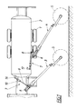
- a tunnel washing vehicle was essentially only the one on the chassis and the wheels 1 supported tank 2 for the washing liquid.
- two brush arms 3, 4 are attached.
- the rotatably drivable and at one end adjustable washing brushes 5 carries and with its other end to one not shown transverse axis can be pivoted up and down and about a vertical axis 6 is pivotable to the side.
- a drive device according to the invention engages on the boom 3 7, which serves the pivoting about the vertical axis 6, immediately on, whereas a drive device 7 for the second boom 4 over a lever 8 is connected to this boom 4.
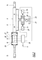
- the drive device consists of a hydraulically operated cylinder-piston unit 9 and a pneumatic one actuatable cylinder-piston unit 10.
- the cylinders 11, 12 of the cylinder-piston units 9, 10 are connected via an adapter plate 13 and the piston rods 14, 15 of the two cylinder-piston units 9, 10 are opposite Pages led out and on a support 16 and 17 on the vehicle and on Boom 3 or articulated on the lever 8 of the boom 4.
- the pressurization lines 18, 19 for the cylinder 11 the hydraulically actuated cylinder-piston unit 9 lead to a piston spool 20 indicated hydraulic regulator, the two inputs for connection has a feed pump 21 and a return line 22 in the illustrated Middle position the line 18, 19 blocks and thus the hydraulically operated Cylinder-piston unit 9 fixed in the current extended position, as well as in the two working positions, the lines 18, 19 alternately with the pump 21 and Return 22 connects.
- Working magnets 23, 24 determine when they are switched on the two working positions. For the actuation of these working magnets 23, 24 a central control unit 25 is provided, which is connected to sensors 26, 27 is.
- the control unit 25 switches the working magnet 23 a so that this connects the pump 21 to the line 18 and the piston 14 of the cylinder-piston unit 9 is urged in the direction of extension. Reached the piston of the cylinder-piston unit 7 the sensor 27, then switches Control unit 25, the working magnet 24, so that the control slide 20 Pump 21 connects to line 19 and line 18 to the return 22 so that the piston 14 of the cylinder-piston unit 9 moves back into the cylinder 11.
- the duration of exposure to the hydraulic cylinder-piston unit 9 can be regulated by a timer. Another option is on the pneumatically actuated cylinder-piston unit 10 a z.
Landscapes
- Engineering & Computer Science (AREA)
- General Engineering & Computer Science (AREA)
- Physics & Mathematics (AREA)
- Fluid Mechanics (AREA)
- Mechanical Engineering (AREA)
- Analytical Chemistry (AREA)
- Chemical & Material Sciences (AREA)
- Architecture (AREA)
- Civil Engineering (AREA)
- Structural Engineering (AREA)
- Cleaning In General (AREA)
- Fluid-Pressure Circuits (AREA)
- Manipulator (AREA)
Abstract
Description
- Fig. 1
- den Hauptteil eines mit zwei Bürstenauslegern ausgestatteten Tunnel-Waschfahrzeuges bei ausgestellten Bürstenauslegern in Draufsicht und
- Fig. 2
- eine erfindungsgemäße Antriebseinrichtung mit einer schematisch eingezeichneten Regeleinrichtung in größerem Maßstab.
Claims (4)
- Antriebseinrichtung zur Schwenkeinstellung eines Bürstenauslegers (3, 4) eines Tunnelwaschfahrzeuges (1, 2), mit einer hydraulisch betätigbaren Zylinder-Kolbeneinheit (9), dadurch gekennzeichnet, daß für die hydraulisch betätigbare Zylinder-Kolbeneinheit (9) eine Verlängerung aus einer pneumatisch betätigbaren Zylinder-Kolbeneinheit (10) vorgesehen ist.
- Antriebseinrichtung nach Anspruch 1, dadurch gekennzeichnet, daß die hydraulisch betätigbare Zylinder-Kolbeneinheit (9) den größeren, die pneumatisch betätigbare Zylinder-Kolbeneinheit (10) aber nur einen kleineren Teil des möglichen Gesamtverstellweges bestimmt.
- Antriebseinrichtung nach Anspruch 1 oder 2, dadurch gekennzeichnet, daß jede der beiden Zylinder-Kolbeneinheiten (9, 10) aus Zylinder (11, 12), Kolben und Kolbenstange (14, 15) besteht, die beiden Zylinder (11, 12) miteinander verbunden und die an Abstützungen (8, 16, 17) am Fahrzeug bzw. Ausleger (3) angreifenden Kolbenstangen (14, 15) nach entgegengesetzten Seiten herausgeführt sind.
- Antriebseinrichtung nach einem der Ansprüche 1 bis 3, dadurch gekennzeichnet, daß für die pneumatisch betätigbare Zylinder-Kolbeneinheit (10) ein oder mehrere Lagefühler (26 - 28) vorgesehen sind, die über eine Steuereinrichtung (20, 25) die Beaufschlagung der hydraulisch betätigbaren Zylinder-Kolbeneinheit (9) im Sinne einer Nachführsteuerung regeln.
Priority Applications (1)
| Application Number | Priority Date | Filing Date | Title |
|---|---|---|---|
| AT99890156T ATE274143T1 (de) | 1998-07-14 | 1999-05-19 | Bürstenauslegervorrichtung eines tunnelwaschfahrzeuges |
Applications Claiming Priority (4)
| Application Number | Priority Date | Filing Date | Title |
|---|---|---|---|
| AT47198U | 1998-07-14 | ||
| AT0047198U AT2939U1 (de) | 1998-07-14 | 1998-07-14 | Antriebseinrichtung zur schwenkeinstellung eines bürstenauslegers eines tunnelwaschfahrzeuges |
| AT24199U | 1999-04-13 | ||
| AT24199U AT3380U1 (de) | 1999-04-13 | 1999-04-13 | Antriebseinrichtung zur schwenkeinstellung eines bürstenauslegers eines tunnelwaschfahrzeuges |
Publications (3)
| Publication Number | Publication Date |
|---|---|
| EP0972947A2 true EP0972947A2 (de) | 2000-01-19 |
| EP0972947A3 EP0972947A3 (de) | 2002-04-17 |
| EP0972947B1 EP0972947B1 (de) | 2004-08-18 |
Family
ID=25592000
Family Applications (1)
| Application Number | Title | Priority Date | Filing Date |
|---|---|---|---|
| EP19990890156 Expired - Lifetime EP0972947B1 (de) | 1998-07-14 | 1999-05-19 | Bürstenauslegervorrichtung eines Tunnelwaschfahrzeuges |
Country Status (2)
| Country | Link |
|---|---|
| EP (1) | EP0972947B1 (de) |
| DE (1) | DE59910253D1 (de) |
Cited By (1)
| Publication number | Priority date | Publication date | Assignee | Title |
|---|---|---|---|---|
| AT6809U3 (de) * | 2003-12-19 | 2004-11-25 | Zellinger Gmbh | Fahrzeug |
Families Citing this family (1)
| Publication number | Priority date | Publication date | Assignee | Title |
|---|---|---|---|---|
| CN101967806B (zh) * | 2010-07-05 | 2011-11-30 | 湖南恒润高科股份有限公司 | 道路清扫车扫盘的双气压控制升降装置 |
Citations (2)
| Publication number | Priority date | Publication date | Assignee | Title |
|---|---|---|---|---|
| AT344232B (de) | 1976-01-14 | 1978-07-10 | Zellinger Gmbh | Tunnelwaschfahrzeug |
| EP0184577A2 (de) | 1984-12-04 | 1986-06-11 | Zellinger Gesellschaft m.b.H. | Bürstenausleger für ein Tunnelwaschfahrzeug |
Family Cites Families (2)
| Publication number | Priority date | Publication date | Assignee | Title |
|---|---|---|---|---|
| FR1403051A (fr) * | 1964-05-06 | 1965-06-18 | Materiel De Voirie | Engin automoteur pour nettoiement des parois de souterrains |
| JPS60147269A (ja) * | 1984-01-10 | 1985-08-03 | Mitsubishi Heavy Ind Ltd | 壁面研掃・塗装装置 |
-
1999
- 1999-05-19 EP EP19990890156 patent/EP0972947B1/de not_active Expired - Lifetime
- 1999-05-19 DE DE59910253T patent/DE59910253D1/de not_active Expired - Lifetime
Patent Citations (2)
| Publication number | Priority date | Publication date | Assignee | Title |
|---|---|---|---|---|
| AT344232B (de) | 1976-01-14 | 1978-07-10 | Zellinger Gmbh | Tunnelwaschfahrzeug |
| EP0184577A2 (de) | 1984-12-04 | 1986-06-11 | Zellinger Gesellschaft m.b.H. | Bürstenausleger für ein Tunnelwaschfahrzeug |
Cited By (3)
| Publication number | Priority date | Publication date | Assignee | Title |
|---|---|---|---|---|
| AT6809U3 (de) * | 2003-12-19 | 2004-11-25 | Zellinger Gmbh | Fahrzeug |
| EP1544356A2 (de) * | 2003-12-19 | 2005-06-22 | Zellinger Gesellschaft m.b.H. | Fahrzeug |
| EP1544356A3 (de) * | 2003-12-19 | 2006-02-15 | Zellinger Gesellschaft m.b.H. | Fahrzeug |
Also Published As
| Publication number | Publication date |
|---|---|
| DE59910253D1 (de) | 2004-09-23 |
| EP0972947B1 (de) | 2004-08-18 |
| EP0972947A3 (de) | 2002-04-17 |
Similar Documents
| Publication | Publication Date | Title |
|---|---|---|
| EP0686224B2 (de) | Grossmanipulator, insbesondere für autobetonpumpen | |
| DE10350531A1 (de) | Verfahren zur Steuerung eines Tisches und Tischsystem | |
| DE102015102422A1 (de) | Verfahren zur Bewegungssteuerung und/oder Regelung einer landwirtschaftlichen Verteilvorrichtung | |
| DE202014000508U1 (de) | Bohrgerät | |
| DE2721553B2 (de) | Maschine zum Schleifen und Polieren von Werkstücken mit sphärischer Oberfläche, wie Brillengläser o.dgl | |
| DE19927593C1 (de) | Kehraggregat | |
| DE3004082A1 (de) | Einrichtung zur steuerung der schwenkbewegung eines schienenfahrzeuges in einer kurve | |
| EP0972947B1 (de) | Bürstenauslegervorrichtung eines Tunnelwaschfahrzeuges | |
| DE2318272A1 (de) | Hydraulische steuervorrichtung fuer die automatische fernsteuerung eines hydraulischen stellzylinders | |
| DE1293996B (de) | In mehreren Freiheitsgraden mechanisch steuerbares Handhabungsgeraet | |
| DE3439213A1 (de) | Lenkfuehrungsanordnung | |
| DE2033773C3 (de) | An einem Fahrzeug aufgehängter Sprühbalken für Schädlingsbekämpfungsmittel | |
| DE1658384B1 (de) | Selbstaufnehmende Strassenkehrmaschine | |
| DE3642809C2 (de) | ||
| AT3380U1 (de) | Antriebseinrichtung zur schwenkeinstellung eines bürstenauslegers eines tunnelwaschfahrzeuges | |
| DE2658420A1 (de) | Tunnelwaschfahrzeug | |
| DE2222981A1 (de) | Schwemmaggregat | |
| DE2153544C3 (de) | Vorrichtung zum Abfräsen von Straßendecken | |
| DE4123836C1 (en) | Suspension system for road sweeping equipment - has cylinders connected to roller with pistons to control vertical motion | |
| DE1530281C3 (de) | Vorrichtung zum ortsgenauen Abstellen eines Schienenfahrzeuges | |
| AT390348B (de) | Verfahren zur steuerung der eindringtiefe von bodenbearbeitungsgeraeten, steueranordnung zu dessen durchfuehrung und bodenbearbeitungsgeraet | |
| DE2925223A1 (de) | Vorrichtung zum ueberwachen der verschiebung einer lichtbogenofen-elektrode | |
| DE19611582C2 (de) | Mähfahrzeug mit einem Sammelbehälter | |
| AT2939U1 (de) | Antriebseinrichtung zur schwenkeinstellung eines bürstenauslegers eines tunnelwaschfahrzeuges | |
| AT6809U2 (de) | Fahrzeug |
Legal Events
| Date | Code | Title | Description |
|---|---|---|---|
| PUAI | Public reference made under article 153(3) epc to a published international application that has entered the european phase |
Free format text: ORIGINAL CODE: 0009012 |
|
| AK | Designated contracting states |
Kind code of ref document: A2 Designated state(s): AT BE CH CY DE DK ES FI FR GB GR IE IT LI LU MC NL PT SE Kind code of ref document: A2 Designated state(s): AT CH DE FR LI LU |
|
| AX | Request for extension of the european patent |
Free format text: AL;LT;LV;MK;RO;SI |
|
| PUAL | Search report despatched |
Free format text: ORIGINAL CODE: 0009013 |
|
| AK | Designated contracting states |
Kind code of ref document: A3 Designated state(s): AT BE CH CY DE DK ES FI FR GB GR IE IT LI LU MC NL PT SE |
|
| AX | Request for extension of the european patent |
Free format text: AL;LT;LV;MK;RO;SI |
|
| RIC1 | Information provided on ipc code assigned before grant |
Free format text: 7F 15B 11/072 A, 7E 01H 1/00 B, 7F 15B 11/13 B |
|
| 17P | Request for examination filed |
Effective date: 20021002 |
|
| AKX | Designation fees paid |
Free format text: AT CH DE FR LI LU |
|
| 17Q | First examination report despatched |
Effective date: 20030514 |
|
| GRAP | Despatch of communication of intention to grant a patent |
Free format text: ORIGINAL CODE: EPIDOSNIGR1 |
|
| RTI1 | Title (correction) |
Free format text: BRUSH BOOM SYSTEM OF A TUNNEL WASHING VEHICLE |
|
| GRAS | Grant fee paid |
Free format text: ORIGINAL CODE: EPIDOSNIGR3 |
|
| GRAA | (expected) grant |
Free format text: ORIGINAL CODE: 0009210 |
|
| AK | Designated contracting states |
Kind code of ref document: B1 Designated state(s): AT CH DE FR LI LU |
|
| REG | Reference to a national code |
Ref country code: CH Ref legal event code: EP |
|
| REG | Reference to a national code |
Ref country code: IE Ref legal event code: FG4D Free format text: GERMAN |
|
| REF | Corresponds to: |
Ref document number: 59910253 Country of ref document: DE Date of ref document: 20040923 Kind code of ref document: P |
|
| REG | Reference to a national code |
Ref country code: IE Ref legal event code: FD4D |
|
| PLBE | No opposition filed within time limit |
Free format text: ORIGINAL CODE: 0009261 |
|
| STAA | Information on the status of an ep patent application or granted ep patent |
Free format text: STATUS: NO OPPOSITION FILED WITHIN TIME LIMIT |
|
| ET | Fr: translation filed | ||
| 26N | No opposition filed |
Effective date: 20050519 |
|
| REG | Reference to a national code |
Ref country code: CH Ref legal event code: PFA Owner name: ZELLINGER GESELLSCHAFT M.B.H. Free format text: ZELLINGER GESELLSCHAFT M.B.H.#KREMSTALSTRASSE 102#A-4050 TRAUN (AT) -TRANSFER TO- ZELLINGER GESELLSCHAFT M.B.H.#KREMSTALSTRASSE 102#A-4050 TRAUN (AT) |
|
| PGFP | Annual fee paid to national office [announced via postgrant information from national office to epo] |
Ref country code: LU Payment date: 20090525 Year of fee payment: 11 |
|
| PGFP | Annual fee paid to national office [announced via postgrant information from national office to epo] |
Ref country code: FR Payment date: 20100609 Year of fee payment: 12 |
|
| PGFP | Annual fee paid to national office [announced via postgrant information from national office to epo] |
Ref country code: DE Payment date: 20100514 Year of fee payment: 12 Ref country code: AT Payment date: 20100528 Year of fee payment: 12 |
|
| PGFP | Annual fee paid to national office [announced via postgrant information from national office to epo] |
Ref country code: CH Payment date: 20100518 Year of fee payment: 12 |
|
| REG | Reference to a national code |
Ref country code: DE Ref legal event code: R119 Ref document number: 59910253 Country of ref document: DE |
|
| REG | Reference to a national code |
Ref country code: DE Ref legal event code: R119 Ref document number: 59910253 Country of ref document: DE |
|
| REG | Reference to a national code |
Ref country code: CH Ref legal event code: PL |
|
| PG25 | Lapsed in a contracting state [announced via postgrant information from national office to epo] |
Ref country code: CH Free format text: LAPSE BECAUSE OF NON-PAYMENT OF DUE FEES Effective date: 20110531 Ref country code: LI Free format text: LAPSE BECAUSE OF NON-PAYMENT OF DUE FEES Effective date: 20110531 |
|
| REG | Reference to a national code |
Ref country code: AT Ref legal event code: MM01 Ref document number: 274143 Country of ref document: AT Kind code of ref document: T Effective date: 20110519 |
|
| REG | Reference to a national code |
Ref country code: FR Ref legal event code: ST Effective date: 20120131 |
|
| PG25 | Lapsed in a contracting state [announced via postgrant information from national office to epo] |
Ref country code: AT Free format text: LAPSE BECAUSE OF NON-PAYMENT OF DUE FEES Effective date: 20110519 |
|
| PG25 | Lapsed in a contracting state [announced via postgrant information from national office to epo] |
Ref country code: FR Free format text: LAPSE BECAUSE OF NON-PAYMENT OF DUE FEES Effective date: 20110531 |
|
| PG25 | Lapsed in a contracting state [announced via postgrant information from national office to epo] |
Ref country code: LU Free format text: LAPSE BECAUSE OF NON-PAYMENT OF DUE FEES Effective date: 20100519 |
|
| PG25 | Lapsed in a contracting state [announced via postgrant information from national office to epo] |
Ref country code: DE Free format text: LAPSE BECAUSE OF NON-PAYMENT OF DUE FEES Effective date: 20111130 |