EP0971135A1 - Weld stud - Google Patents
Weld stud Download PDFInfo
- Publication number
- EP0971135A1 EP0971135A1 EP99305148A EP99305148A EP0971135A1 EP 0971135 A1 EP0971135 A1 EP 0971135A1 EP 99305148 A EP99305148 A EP 99305148A EP 99305148 A EP99305148 A EP 99305148A EP 0971135 A1 EP0971135 A1 EP 0971135A1
- Authority
- EP
- European Patent Office
- Prior art keywords
- leg portion
- engagement
- weld stud
- stud
- clip
- Prior art date
- Legal status (The legal status is an assumption and is not a legal conclusion. Google has not performed a legal analysis and makes no representation as to the accuracy of the status listed.)
- Withdrawn
Links
- 229920003002 synthetic resin Polymers 0.000 claims abstract description 12
- 239000000057 synthetic resin Substances 0.000 claims abstract description 12
- 238000005452 bending Methods 0.000 claims abstract description 3
- 230000002093 peripheral effect Effects 0.000 claims description 2
- 238000004519 manufacturing process Methods 0.000 description 4
- 230000000712 assembly Effects 0.000 description 3
- 238000000429 assembly Methods 0.000 description 3
- 239000002184 metal Substances 0.000 description 3
- 229910052751 metal Inorganic materials 0.000 description 3
- XEEYBQQBJWHFJM-UHFFFAOYSA-N Iron Chemical compound [Fe] XEEYBQQBJWHFJM-UHFFFAOYSA-N 0.000 description 2
- 229910052742 iron Inorganic materials 0.000 description 1
Images


Classifications
-
- F—MECHANICAL ENGINEERING; LIGHTING; HEATING; WEAPONS; BLASTING
- F16—ENGINEERING ELEMENTS AND UNITS; GENERAL MEASURES FOR PRODUCING AND MAINTAINING EFFECTIVE FUNCTIONING OF MACHINES OR INSTALLATIONS; THERMAL INSULATION IN GENERAL
- F16B—DEVICES FOR FASTENING OR SECURING CONSTRUCTIONAL ELEMENTS OR MACHINE PARTS TOGETHER, e.g. NAILS, BOLTS, CIRCLIPS, CLAMPS, CLIPS OR WEDGES; JOINTS OR JOINTING
- F16B5/00—Joining sheets or plates, e.g. panels, to one another or to strips or bars parallel to them
- F16B5/06—Joining sheets or plates, e.g. panels, to one another or to strips or bars parallel to them by means of clamps or clips
- F16B5/0607—Joining sheets or plates, e.g. panels, to one another or to strips or bars parallel to them by means of clamps or clips joining sheets or plates to each other
- F16B5/0621—Joining sheets or plates, e.g. panels, to one another or to strips or bars parallel to them by means of clamps or clips joining sheets or plates to each other in parallel relationship
- F16B5/0642—Joining sheets or plates, e.g. panels, to one another or to strips or bars parallel to them by means of clamps or clips joining sheets or plates to each other in parallel relationship the plates being arranged one on top of the other and in full close contact with each other
-
- F—MECHANICAL ENGINEERING; LIGHTING; HEATING; WEAPONS; BLASTING
- F16—ENGINEERING ELEMENTS AND UNITS; GENERAL MEASURES FOR PRODUCING AND MAINTAINING EFFECTIVE FUNCTIONING OF MACHINES OR INSTALLATIONS; THERMAL INSULATION IN GENERAL
- F16B—DEVICES FOR FASTENING OR SECURING CONSTRUCTIONAL ELEMENTS OR MACHINE PARTS TOGETHER, e.g. NAILS, BOLTS, CIRCLIPS, CLAMPS, CLIPS OR WEDGES; JOINTS OR JOINTING
- F16B5/00—Joining sheets or plates, e.g. panels, to one another or to strips or bars parallel to them
- F16B5/06—Joining sheets or plates, e.g. panels, to one another or to strips or bars parallel to them by means of clamps or clips
- F16B5/0607—Joining sheets or plates, e.g. panels, to one another or to strips or bars parallel to them by means of clamps or clips joining sheets or plates to each other
- F16B5/0621—Joining sheets or plates, e.g. panels, to one another or to strips or bars parallel to them by means of clamps or clips joining sheets or plates to each other in parallel relationship
- F16B5/0657—Joining sheets or plates, e.g. panels, to one another or to strips or bars parallel to them by means of clamps or clips joining sheets or plates to each other in parallel relationship at least one of the plates providing a raised structure, e.g. of the doghouse type, for connection with the clamps or clips of the other plate
-
- F—MECHANICAL ENGINEERING; LIGHTING; HEATING; WEAPONS; BLASTING
- F16—ENGINEERING ELEMENTS AND UNITS; GENERAL MEASURES FOR PRODUCING AND MAINTAINING EFFECTIVE FUNCTIONING OF MACHINES OR INSTALLATIONS; THERMAL INSULATION IN GENERAL
- F16B—DEVICES FOR FASTENING OR SECURING CONSTRUCTIONAL ELEMENTS OR MACHINE PARTS TOGETHER, e.g. NAILS, BOLTS, CIRCLIPS, CLAMPS, CLIPS OR WEDGES; JOINTS OR JOINTING
- F16B5/00—Joining sheets or plates, e.g. panels, to one another or to strips or bars parallel to them
- F16B5/06—Joining sheets or plates, e.g. panels, to one another or to strips or bars parallel to them by means of clamps or clips
- F16B5/0607—Joining sheets or plates, e.g. panels, to one another or to strips or bars parallel to them by means of clamps or clips joining sheets or plates to each other
- F16B5/0621—Joining sheets or plates, e.g. panels, to one another or to strips or bars parallel to them by means of clamps or clips joining sheets or plates to each other in parallel relationship
- F16B5/0664—Joining sheets or plates, e.g. panels, to one another or to strips or bars parallel to them by means of clamps or clips joining sheets or plates to each other in parallel relationship at least one of the sheets or plates having integrally formed or integrally connected snap-in-features
-
- F—MECHANICAL ENGINEERING; LIGHTING; HEATING; WEAPONS; BLASTING
- F16—ENGINEERING ELEMENTS AND UNITS; GENERAL MEASURES FOR PRODUCING AND MAINTAINING EFFECTIVE FUNCTIONING OF MACHINES OR INSTALLATIONS; THERMAL INSULATION IN GENERAL
- F16B—DEVICES FOR FASTENING OR SECURING CONSTRUCTIONAL ELEMENTS OR MACHINE PARTS TOGETHER, e.g. NAILS, BOLTS, CIRCLIPS, CLAMPS, CLIPS OR WEDGES; JOINTS OR JOINTING
- F16B21/00—Means for preventing relative axial movement of a pin, spigot, shaft or the like and a member surrounding it; Stud-and-socket releasable fastenings
- F16B21/06—Releasable fastening devices with snap-action
- F16B21/08—Releasable fastening devices with snap-action in which the stud, pin, or spigot has a resilient part
- F16B21/086—Releasable fastening devices with snap-action in which the stud, pin, or spigot has a resilient part the shank of the stud, pin or spigot having elevations, ribs, fins or prongs intended for deformation or tilting predominantly in a direction perpendicular to the direction of insertion
-
- F—MECHANICAL ENGINEERING; LIGHTING; HEATING; WEAPONS; BLASTING
- F16—ENGINEERING ELEMENTS AND UNITS; GENERAL MEASURES FOR PRODUCING AND MAINTAINING EFFECTIVE FUNCTIONING OF MACHINES OR INSTALLATIONS; THERMAL INSULATION IN GENERAL
- F16B—DEVICES FOR FASTENING OR SECURING CONSTRUCTIONAL ELEMENTS OR MACHINE PARTS TOGETHER, e.g. NAILS, BOLTS, CIRCLIPS, CLAMPS, CLIPS OR WEDGES; JOINTS OR JOINTING
- F16B21/00—Means for preventing relative axial movement of a pin, spigot, shaft or the like and a member surrounding it; Stud-and-socket releasable fastenings
- F16B21/06—Releasable fastening devices with snap-action
- F16B21/08—Releasable fastening devices with snap-action in which the stud, pin, or spigot has a resilient part
- F16B21/088—Releasable fastening devices with snap-action in which the stud, pin, or spigot has a resilient part the stud, pin or spigot being integrally formed with the component to be fastened, e.g. forming part of the sheet, plate or strip
-
- F—MECHANICAL ENGINEERING; LIGHTING; HEATING; WEAPONS; BLASTING
- F16—ENGINEERING ELEMENTS AND UNITS; GENERAL MEASURES FOR PRODUCING AND MAINTAINING EFFECTIVE FUNCTIONING OF MACHINES OR INSTALLATIONS; THERMAL INSULATION IN GENERAL
- F16B—DEVICES FOR FASTENING OR SECURING CONSTRUCTIONAL ELEMENTS OR MACHINE PARTS TOGETHER, e.g. NAILS, BOLTS, CIRCLIPS, CLAMPS, CLIPS OR WEDGES; JOINTS OR JOINTING
- F16B37/00—Nuts or like thread-engaging members
- F16B37/08—Quickly-detachable or mountable nuts, e.g. consisting of two or more parts; Nuts movable along the bolt after tilting the nut
- F16B37/0807—Nuts engaged from the end of the bolt, e.g. axially slidable nuts
- F16B37/0842—Nuts engaged from the end of the bolt, e.g. axially slidable nuts fastened to the threaded bolt with snap-on-action, e.g. push-on nuts for stud bolts
-
- Y—GENERAL TAGGING OF NEW TECHNOLOGICAL DEVELOPMENTS; GENERAL TAGGING OF CROSS-SECTIONAL TECHNOLOGIES SPANNING OVER SEVERAL SECTIONS OF THE IPC; TECHNICAL SUBJECTS COVERED BY FORMER USPC CROSS-REFERENCE ART COLLECTIONS [XRACs] AND DIGESTS
- Y10—TECHNICAL SUBJECTS COVERED BY FORMER USPC
- Y10T—TECHNICAL SUBJECTS COVERED BY FORMER US CLASSIFICATION
- Y10T24/00—Buckles, buttons, clasps, etc.
- Y10T24/30—Trim molding fastener
- Y10T24/309—Plastic type
-
- Y—GENERAL TAGGING OF NEW TECHNOLOGICAL DEVELOPMENTS; GENERAL TAGGING OF CROSS-SECTIONAL TECHNOLOGIES SPANNING OVER SEVERAL SECTIONS OF THE IPC; TECHNICAL SUBJECTS COVERED BY FORMER USPC CROSS-REFERENCE ART COLLECTIONS [XRACs] AND DIGESTS
- Y10—TECHNICAL SUBJECTS COVERED BY FORMER USPC
- Y10T—TECHNICAL SUBJECTS COVERED BY FORMER US CLASSIFICATION
- Y10T24/00—Buckles, buttons, clasps, etc.
- Y10T24/34—Combined diverse multipart fasteners
- Y10T24/3427—Clasp
- Y10T24/3439—Plural clasps
- Y10T24/344—Resilient type clasp
Definitions
- the present invention relates to a weld stud which is welded to a workpiece and attaches a component to the workpiece, and an attachment assembly using the weld stud. More specifically, the present invention relates to a weld stud which is effective in being utilised, but not limited, as a synthetic resin weld stud to be welded to a box member made of synthetic resin such as a dashboard or some other structural part of an automobile, or a cowling of a motorcycle.
- a clip assembly commonly used for attaching a component on a box member made of synthetic resin such as a dashboard of an automobile or a cowling of a motorcycle
- the root of a weld stud 1 having an engagement step la at a longitudinally mid portion is welded to a box panel 2
- a clip 3 comprises a tubular leg portion 3a with an inner diameter enough to receive the stud 1 and a disc-like head 3b formed on an upper end of the leg portion.
- the clip 3 is brought into engagement with the stud 1, thereby holding another component 4 sandwiched between the head 3b and the box-like panel 2.
- resilient engagement pawls 3 are provided in the manner that they extend inwardly with respect to the tubular leg portion 3a of the clip 3, and the engagement pawls 3c are brought into engagement with the engagement step la of the stud 1.
- the present invention aims to provide an attachment assembly which can be used in common with various components to be attached without being changed depending on the various components and be removed easily after mounted and, further, to provide a weld stud for use with the above attachment assembly.
- a weld stud according to the present invention comprises a leg portion having a root adapted to be welded to a workpiece, and a resilient engagement pawl portion integrally formed on at least one side of the leg portion.
- the resilient engagement pawl portion extends diagonally outwardly from the end of the leg portion toward the root portion to be capable of bending radially inwardly with respect to the leg portion, and an engagement step which is an inward recess formed on the lower end outside portion of the leg portion.
- a weld stud according to the present invention is not necessarily made of synthetic resin, it is preferred that the weld stud is made of synthetic resin and is moulded as a one-piece article since its use is predominantly for synthetic resin members.
- the leg portion is formed to have substantially flat surfaces on both sides thereof and engagement pawl portions in a pair are formed respectively along the substantially flat surfaces on both sides of the leg portion.
- an attachment assembly comprising a weld stud of any of the above-described types and a clip including an engagement portion to engage with the weld stud.
- the clip is formed with a hole having a radius as sized so as to allow the engagement pawl portion or portions of the weld stud to bend and pass therethrough.
- the clip is provided with a substantially flat engagement surface defining an engagement portion on the upper peripheral surface of the hole.
- a component to be attached may be formed with an attachment portion having an engagement portion or an engagement surface to engage with the stud.
- less kinds of weld studs than the clips can be used and the same type of the clip can be used in different places, so that manufacturing costs can be reduced by providing engagement means in the stud itself.
- Even in another case of using a clip only a hole should be formed in the clip, so that the manufacture cost of the clip can be reduced.
- the engagement pawl portion of the stud of the present invention after the weld stud is attached, the engagement pawl portion can be bent from outside to allow the component to be removed.
- FIG. 1 is a sectional view showing an example of a component attachment assembly of a conventional structure.
- FIG. 2 shows an embodiment weld stud of the present invention
- (a) is a front view
- (b) is a side view.
- FIG. 3 is a sectional view showing an example in which the stud of FIG. 2 is used without a mounting clip.
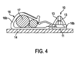
- FIG. 4 is a sectional view showing an example in which a component is attached by means of the stud of FIG. 2 using a mounting clip.
- Fig. 2 (a) and (b) are a front view and a side view of a weld stud (10) of an embodiment according to the present invention.
- the stud (10) has an appropriate flat mounting seat (11) which is, for example, a circle in the form, and a mounting leg portion (12) which extend upwardly from the mounting seat (11) and has flat sides (12a).
- a pair of resilient engagement pawl portions (13) are formed so as to extend from the upper end of the leg portion (12) toward the root of the leg portion diagonally outwardly downwardly.
- an engagement step (13a) is formed as an inward recess.
- the weld stud is made of synthetic resin and is formed as a one-piece article.
- the stud (10) is welded at its mounting seat (11) to a workpiece panel such as a box panel (14) made of synthetic resin.
- an attachment component (15) is mounted directly on the box panel (14), without using any mounting clip.
- the attachment component (15) is formed with a hole (15)a to be penetrated by the stud (10).
- an inwardly projecting engagement portion (15b) is formed on the inner wall of the hole (15a.
- the engagement portion (15b) is formed with a hole (15c) having a diameter which allows the engagement portions (13) to bend and pass therethrough, and the top surface of the engagement portion (15b) defines an engagement surface.
- the attachment component (15) is fixed onto the box panel (14) when the engagement steps (13a) of the engagement pawl portions (13) of the stud (10) come into engagement with the engagement surface on the top of the engagement portion (15b) of the attachment component (15).
- Fig. 4 shows an example of using the embodiment weld stud (10) of the present invention for mounting a clip (16) for an electric wire.
- the clip (16) has a holder portion (16a) to hold a wire (17) or the like and a mounting portion (16b) formed integrally at an end portion of the holder portion (16a).
- the mounting portion (16b) may be a simple, disc-like member. It suffices that the mounting portion is formed with, for example, a round hole which allows the engagement pawl portions (13) of the stud (10) to bend and pass through. In this case, the top surface of the mounting portion (16b) defines an engagement surface. Since the mounting portion (16b) of the clip (16) can be in a simple annular form, manufacturing costs will be reduced remarkably.
- the engagement pawl portions (13) of the stud (10) are formed on both sides of the leg portion (12). Nevertheless, the engagement pawl portion formed only on one of the side can satisfactorily fulfil the intended function. It is also possible that the weld stud is made of metal such as iron-based metal.
Landscapes
- Engineering & Computer Science (AREA)
- General Engineering & Computer Science (AREA)
- Mechanical Engineering (AREA)
- Connection Of Plates (AREA)
- Snaps, Bayonet Connections, Set Pins, And Snap Rings (AREA)
- Lining Or Joining Of Plastics Or The Like (AREA)
- Standing Axle, Rod, Or Tube Structures Coupled By Welding, Adhesion, Or Deposition (AREA)
Applications Claiming Priority (2)
| Application Number | Priority Date | Filing Date | Title |
|---|---|---|---|
| JP10190525A JP2000018223A (ja) | 1998-07-06 | 1998-07-06 | 溶着スタッド |
| JP19052598 | 1998-07-06 |
Publications (1)
| Publication Number | Publication Date |
|---|---|
| EP0971135A1 true EP0971135A1 (en) | 2000-01-12 |
Family
ID=16259550
Family Applications (1)
| Application Number | Title | Priority Date | Filing Date |
|---|---|---|---|
| EP99305148A Withdrawn EP0971135A1 (en) | 1998-07-06 | 1999-06-30 | Weld stud |
Country Status (4)
| Country | Link |
|---|---|
| US (1) | US6205625B1 (enExample) |
| EP (1) | EP0971135A1 (enExample) |
| JP (1) | JP2000018223A (enExample) |
| DE (1) | DE19929924A1 (enExample) |
Cited By (5)
| Publication number | Priority date | Publication date | Assignee | Title |
|---|---|---|---|---|
| EP1069326A3 (de) * | 1999-07-14 | 2002-01-30 | A. Raymond & Cie | Halteelement zur lösbaren Befestigung auf einem längsgerippten Kunststoffbolzen |
| BE1014438A3 (nl) * | 2001-10-24 | 2003-10-07 | Novalati Nv | Inrichting voor het aan elkaar bevestigen van twee elementen. |
| EP1580078A3 (en) * | 2004-03-25 | 2005-10-19 | Aisin Seiki Kabushiki Kaisha | Metal scuff plate |
| EP2977624A1 (en) * | 2014-07-22 | 2016-01-27 | Aktiebolaget SKF | Identification system with electronic tag for identifying a rolling bearing and hub bearing unit equipped therewith |
| CN107850097A (zh) * | 2015-06-25 | 2018-03-27 | 利富高美国有限公司 | 卡子 |
Families Citing this family (14)
| Publication number | Priority date | Publication date | Assignee | Title |
|---|---|---|---|---|
| DE10012781A1 (de) * | 2000-03-16 | 2001-09-27 | Boellhoff Gmbh | Verbindungsanordnung zum Anbringen eines Befestigungselementes an einem Bauteil |
| KR100451530B1 (ko) * | 2001-10-23 | 2004-10-06 | 박자영 | 식생 방음판의 방음 막대 고정 구조 |
| EP1446585A1 (en) * | 2001-11-21 | 2004-08-18 | Newfrey LLC | Plastic retaining clip for rib attachment |
| US7114221B2 (en) * | 2003-01-17 | 2006-10-03 | Newfrey Llc | Two-piece interior trim retainer |
| US20070068717A1 (en) * | 2005-09-27 | 2007-03-29 | Austin James B | Hidden fastening system for motor vehicle instrument panels |
| DE102006032641A1 (de) * | 2006-07-13 | 2008-01-17 | Newfrey Llc, Newark | Befestigungselement |
| US7614125B2 (en) * | 2006-08-07 | 2009-11-10 | Newfrey Llc | Positive hold tube weld stud assembly |
| US8365928B1 (en) * | 2009-06-02 | 2013-02-05 | Design Display Group, Inc. | Gondola standard cover |
| DE102010048956A1 (de) * | 2010-10-15 | 2012-04-19 | Illinois Tool Works Inc. | Vorrichtung und Verfahren zur Befestigung eines mindestens eine Öffnung aufweisenden Bauteils an einem Trägerteil |
| US9752607B2 (en) | 2013-03-13 | 2017-09-05 | Rolls-Royce North American Technologies, Inc. | Retention pin and method of forming |
| EP2971582B1 (en) | 2013-03-13 | 2019-05-08 | Rolls-Royce North American Technologies, Inc. | Retention pin and method of forming |
| US11813701B2 (en) | 2016-04-19 | 2023-11-14 | Dtech Precision Industries Co., Ltd. | Method of fitting the soldering component to board |
| US20200276663A1 (en) * | 2016-04-19 | 2020-09-03 | Dtech Precision Industries Co., Ltd. | Welding connection element |
| US10100863B2 (en) * | 2016-07-27 | 2018-10-16 | GM Global Technology Operations LLC | External heat-stake arrangement |
Citations (6)
| Publication number | Priority date | Publication date | Assignee | Title |
|---|---|---|---|---|
| US3909883A (en) * | 1972-02-28 | 1975-10-07 | Richco Plastic Co | Locking base for plastic components |
| DE3908367C1 (en) * | 1989-03-15 | 1990-07-05 | Bayerische Motoren Werke Ag, 8000 Muenchen, De | Device for fixing a bolt on a component |
| US5005265A (en) * | 1988-07-20 | 1991-04-09 | Lavidson Textron Inc. | Two-piece stud assembly |
| US5062382A (en) * | 1989-03-14 | 1991-11-05 | Seikosha Co., Ltd. | Feeder |
| US5143500A (en) * | 1991-02-28 | 1992-09-01 | Itw Plastiglide | Snap engaging fastener system for providing rotary motion |
| US5716161A (en) * | 1996-08-22 | 1998-02-10 | Ankara Industries, Inc. | Retainer clip |
Family Cites Families (12)
| Publication number | Priority date | Publication date | Assignee | Title |
|---|---|---|---|---|
| JPS5721806A (en) | 1980-07-16 | 1982-02-04 | Tdk Corp | Forming method and device for drum-shaped core |
| US4541153A (en) * | 1983-02-08 | 1985-09-17 | Usm Corporation | Mounting clip |
| JPS60203547A (ja) | 1984-03-28 | 1985-10-15 | Toyoda Gosei Co Ltd | 合成樹脂製取付部材の取着部材組付構造 |
| US4636124A (en) * | 1985-05-06 | 1987-01-13 | Illinois Tool Works Inc. | Adhesive friction weld fastener |
| JPS6328633A (ja) * | 1986-07-23 | 1988-02-06 | Nifco Inc | 樹脂製回転溶着部材 |
| US4822224A (en) * | 1987-11-05 | 1989-04-18 | Chrysler Motors Corporation | Harness retainer stud |
| JP2974735B2 (ja) | 1990-07-24 | 1999-11-10 | 富士重工業株式会社 | 鉄道車両の内張板支持構造 |
| US5253965A (en) * | 1992-04-13 | 1993-10-19 | Progressive Tool & Industries Co. | Piercing fastener with adhesive |
| JP2738503B2 (ja) * | 1994-05-27 | 1998-04-08 | 松下電器産業株式会社 | 保持具の係止構造 |
| JPH08135632A (ja) * | 1994-09-12 | 1996-05-31 | Nifco Inc | 部材の取付具 |
| US5660513A (en) * | 1995-07-19 | 1997-08-26 | Illinois Tool Works Inc. | Stud clip having different insertion/withdrawal forces |
| US5803413A (en) * | 1996-11-21 | 1998-09-08 | Avery Dennison Corporation | Cable tie having a stud mountable fastener |
-
1998
- 1998-07-06 JP JP10190525A patent/JP2000018223A/ja active Pending
-
1999
- 1999-06-25 US US09/344,430 patent/US6205625B1/en not_active Expired - Fee Related
- 1999-06-29 DE DE19929924A patent/DE19929924A1/de not_active Withdrawn
- 1999-06-30 EP EP99305148A patent/EP0971135A1/en not_active Withdrawn
Patent Citations (7)
| Publication number | Priority date | Publication date | Assignee | Title |
|---|---|---|---|---|
| US3909883A (en) * | 1972-02-28 | 1975-10-07 | Richco Plastic Co | Locking base for plastic components |
| US3909883B1 (enExample) * | 1972-02-28 | 1985-11-19 | ||
| US5005265A (en) * | 1988-07-20 | 1991-04-09 | Lavidson Textron Inc. | Two-piece stud assembly |
| US5062382A (en) * | 1989-03-14 | 1991-11-05 | Seikosha Co., Ltd. | Feeder |
| DE3908367C1 (en) * | 1989-03-15 | 1990-07-05 | Bayerische Motoren Werke Ag, 8000 Muenchen, De | Device for fixing a bolt on a component |
| US5143500A (en) * | 1991-02-28 | 1992-09-01 | Itw Plastiglide | Snap engaging fastener system for providing rotary motion |
| US5716161A (en) * | 1996-08-22 | 1998-02-10 | Ankara Industries, Inc. | Retainer clip |
Cited By (7)
| Publication number | Priority date | Publication date | Assignee | Title |
|---|---|---|---|---|
| EP1069326A3 (de) * | 1999-07-14 | 2002-01-30 | A. Raymond & Cie | Halteelement zur lösbaren Befestigung auf einem längsgerippten Kunststoffbolzen |
| BE1014438A3 (nl) * | 2001-10-24 | 2003-10-07 | Novalati Nv | Inrichting voor het aan elkaar bevestigen van twee elementen. |
| EP1580078A3 (en) * | 2004-03-25 | 2005-10-19 | Aisin Seiki Kabushiki Kaisha | Metal scuff plate |
| US7264306B2 (en) | 2004-03-25 | 2007-09-04 | Aisin Seiki Kabushiki Kaisha | Metal scuff plate |
| EP2977624A1 (en) * | 2014-07-22 | 2016-01-27 | Aktiebolaget SKF | Identification system with electronic tag for identifying a rolling bearing and hub bearing unit equipped therewith |
| CN107850097A (zh) * | 2015-06-25 | 2018-03-27 | 利富高美国有限公司 | 卡子 |
| CN107850097B (zh) * | 2015-06-25 | 2019-09-17 | 利富高美国有限公司 | 卡子 |
Also Published As
| Publication number | Publication date |
|---|---|
| JP2000018223A (ja) | 2000-01-18 |
| DE19929924A1 (de) | 2000-01-13 |
| US6205625B1 (en) | 2001-03-27 |
Similar Documents
| Publication | Publication Date | Title |
|---|---|---|
| EP0971135A1 (en) | Weld stud | |
| JP3047360U (ja) | エアバッグインフレータ・モジュール用スナップ式装着付設具、固定子スタッド及びドライバー側搭乗者拘束装置 | |
| JPH10500372A (ja) | 車輪トリムとラグナットとを保持する装置 | |
| US6978544B1 (en) | Method of securing ornamentation to a wheel using a retaining article | |
| JP2739876B2 (ja) | ホィールハブキャップ | |
| EP0872649A2 (en) | Mounting system with a fastening stud and a mounting part applied thereto | |
| JP2006513891A (ja) | ステアリングホイールのクラクションを作動させる装置 | |
| JPH08305294A (ja) | エンブレムバッジを取付けるためのプレート | |
| JP2524196Y2 (ja) | 部品の取付構造 | |
| JP2926011B2 (ja) | 配管取付け具 | |
| JP3968685B2 (ja) | バンパメンバ取付構造 | |
| JPH07149104A (ja) | ホイールカバーの装着装置 | |
| JPH021183Y2 (enExample) | ||
| JPS6118536Y2 (enExample) | ||
| JPH0485102A (ja) | ホイールカバー取付装置 | |
| JPH0215001Y2 (enExample) | ||
| JPH0423104Y2 (enExample) | ||
| JPS5816401Y2 (ja) | 車両用ホイ−ルカバ−の固着装置 | |
| JPH0525960Y2 (enExample) | ||
| JPH086671Y2 (ja) | ステアリングホイールへのホーンパット取付構造 | |
| JPH0227682Y2 (enExample) | ||
| KR100320964B1 (ko) | 자동차의 가니쉬 장착용 클립 | |
| JP2546858Y2 (ja) | ホイールキャップ | |
| JP3710500B2 (ja) | クリップ | |
| JPS6018962Y2 (ja) | ホイ−ルキヤツプ |
Legal Events
| Date | Code | Title | Description |
|---|---|---|---|
| PUAI | Public reference made under article 153(3) epc to a published international application that has entered the european phase |
Free format text: ORIGINAL CODE: 0009012 |
|
| AK | Designated contracting states |
Kind code of ref document: A1 Designated state(s): DE GB |
|
| AX | Request for extension of the european patent |
Free format text: AL;LT;LV;MK;RO;SI |
|
| 17P | Request for examination filed |
Effective date: 20000626 |
|
| AKX | Designation fees paid |
Free format text: DE GB |
|
| RAP1 | Party data changed (applicant data changed or rights of an application transferred) |
Owner name: EMHART LLC |
|
| RAP1 | Party data changed (applicant data changed or rights of an application transferred) |
Owner name: NEWFREY LLC |
|
| STAA | Information on the status of an ep patent application or granted ep patent |
Free format text: STATUS: THE APPLICATION IS DEEMED TO BE WITHDRAWN |
|
| 18D | Application deemed to be withdrawn |
Effective date: 20030103 |