EP0970912B2 - Elevator apparatus - Google Patents
Elevator apparatus Download PDFInfo
- Publication number
- EP0970912B2 EP0970912B2 EP99112612A EP99112612A EP0970912B2 EP 0970912 B2 EP0970912 B2 EP 0970912B2 EP 99112612 A EP99112612 A EP 99112612A EP 99112612 A EP99112612 A EP 99112612A EP 0970912 B2 EP0970912 B2 EP 0970912B2
- Authority
- EP
- European Patent Office
- Prior art keywords
- sheave
- hoisting machine
- rotating portion
- fixed
- shaft
- Prior art date
- Legal status (The legal status is an assumption and is not a legal conclusion. Google has not performed a legal analysis and makes no representation as to the accuracy of the status listed.)
- Expired - Lifetime
Links
Images


Classifications
-
- B—PERFORMING OPERATIONS; TRANSPORTING
- B66—HOISTING; LIFTING; HAULING
- B66B—ELEVATORS; ESCALATORS OR MOVING WALKWAYS
- B66B11/00—Main component parts of lifts in, or associated with, buildings or other structures
- B66B11/04—Driving gear ; Details thereof, e.g. seals
- B66B11/043—Driving gear ; Details thereof, e.g. seals actuated by rotating motor; Details, e.g. ventilation
- B66B11/0438—Driving gear ; Details thereof, e.g. seals actuated by rotating motor; Details, e.g. ventilation with a gearless driving, e.g. integrated sheave, drum or winch in the stator or rotor of the cage motor
-
- B—PERFORMING OPERATIONS; TRANSPORTING
- B66—HOISTING; LIFTING; HAULING
- B66B—ELEVATORS; ESCALATORS OR MOVING WALKWAYS
- B66B11/00—Main component parts of lifts in, or associated with, buildings or other structures
- B66B11/0065—Roping
- B66B11/008—Roping with hoisting rope or cable operated by frictional engagement with a winding drum or sheave
Definitions
- the present invention relates to a small-size hoisting machine for an elevator apparatus.
- elevator apparatus provided with hoisting machines which are required to be small-sized have been constructed as disclosed in JP-A-63-277190 , J- B2-7-45315 and JP-A-9-506237 , for example.
- US-A-5,018,603 discloses an elevator hoisting machine with the features included in the first part of claim 1. Similar machines are described in WO-A-95/00432 and in EP-A-0 949 743 , which is an Article 54(3) EPC document.
- An object of the present invention is to provide an elevator hoisting machine which is easy to disassemble and assemble.
- the motor and the sheave can be assembled and disassembled as separate parts, so that the operation can be simple and exchange of the sheave or the like can be individually effected.
- a cage 3 is guided to be able to ascend and descend in an up and down direction by a pair of guide rails 2A, 2B for cage provided to be upright inside an elevator shaft 1 at a distance therebetween.
- the cage 3 has a cage door 3D for passengers and supports shafts of a pair of guide pulleys 4A, 4B on both width sides of a bottom of the cage.
- a main rope 5 is wound on the guide pulleys 4A, 4B and passes through the bottom of the cage 3.
- One end of the main rope 5 is supported, for example, on a beam 6 on the ceiling side of the elevator shaft 1.
- a pair of counterweight guide rails 7A, 7B are provided uprightly with a distance therebetween in parallel to the cage guide rails 2A, 2B, and a counterweight 8 is guided thereby to be movable in a vertical direction.
- a shaft of a guide pulley 9 is supported to an upper portion of the counterweight 8, and the other end of the above-mentioned main rope 5 is wound on the guide pulley 9 and supported on the beam 6 on the ceiling side.
- a support rest 10 is mounted and a hoisting machine 11 is supported on the support base 10.
- the hoisting machine 11 has a sheave 26, and the sheave 26 winds thereon the main rope 5 led to the guide pulley 9 of the counterweight 8 through the guide pulleys 4A, 4B at the bottom of the cage 3.
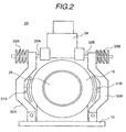
- the hoisting machine 11 is fundamentally constructed on the base 12 fixed to the support rest 10. That is, a fixed frame 13 having a vertical plane 14 is provided on the base 12, and a fixed shaft 15 perpendicular to the vertical plane 14 and extending horizontally is cantilevered by the fixed frame 13.
- the fixed shaft 15 has a large diameter portion 15a at the side of the vertical plane 14 and a small diameter portion 15b at a free end side.
- a rotating frame 16 is rotatably supported on the small diameter portion 15b of the fixed shaft 15 through bearings 18A, 18B.
- the rotating frame 16 is formed in a shape of cylinder with bottom or in a cup-shape by a disc-shaped bottom portion 17 and a peripheral wall 19 formed at the periphery thereof, and a bearing retaining portion 18 is formed at the center of the bottom portion 17.
- the rotating frame 16 is rotatably supported on the small diameter portion 15b of the fixed shaft 15 through the bearings 18A, 18B, whereby an bottom-having cylinder shaped opening side peripheral edge, that is, an opening side peripheral edge of the peripheral wall 19 is placed to be equally close to the vertical plane 14 of the fixed frame 13. It is desirable for stable rotation of the rotating frame 16 to arrange the bearings 18A, 18B at an axial interval therebetween.
- An outer peripheral surface 20 of the bearing retaining portion 18 of the rotating frame 16 and inner and outer peripheral surfaces of the peripheral wall 19 each are formed concentrically with a shaft center of the fixed shaft 15.
- the rotating frame 16 which is supported to be concentric with the fixed shaft 15 in this manner, supports a rotor 21 on the inner periphery of the peripheral wall 19.
- the rotor 21 can be formed by adhering a plurality of permanent magnet pieces on the inner periphery of the peripheral wall 19, or arranging a rotor core having a plurality of permanent magnetic pieces embedded therein on the inner periphery of the peripheral wall 19.
- a stator 22 having a radial gap to the rotor 21 is fixed to the fixed frame 13.
- the stator 22 is composed of a stator core 23 formed by laminating silicon steel plates each having a hole at the center through which the above mentioned fixed shaft passes, and a stator winding 24 wound on the stator core 23.
- the stator 22 is fixed to the fixed frame 13 through a bracket 25.
- An outer rotation type motor is composed of the rotor 21, the stator 22, the fixed frame 13 supporting the stator 22, the rotating frame 16 supporting the rotor 21 and the fixed shaft 15 supporting the rotating frame 16.
- an outer diameter portion of the motor is an outer peripheral surface of the peripheral wall 19 of the rotating frame 16 supporting the rotor 21.
- the rotating frame has the sheave 26 fixed to an outer side of the bottom-having cylindrical bottom portion 17, that is, to the rotating frame 16 at an opposite side to the fixed frame 13. That is, the sheave 26 is fixed by utilizing the outer peripheral surface 20 of the bearing retaining portion 18 formed at the bottom portion 17 of the rotating frame 16 so as to be concentric with the fixed shaft 15.
- the sheave 26 since the rotating frame 16 forms a rotating portion of the motor, the sheave 26 is to be mounted on and fixed to the rotating portion of the motor.
- the sheave 26 is formed so that rope grooves 26G are smaller in diameter than the outer diameter of the motor, that is, the outer peripheral surface of the peripheral wall 19 of the rotating frame 16.
- the sheave 26 is fixed to the rotating frame 17 by screwing bolts 27 into the bottom portion 17 of the rotating frame 16. Further, a mounting hole 28 is formed at a central portion of the sheave 26 so that the center of the mounting hole 28 is the same as the center of rope grooves 26G, and the diameter of the mounting hole 28 is formed in such size that the bearing retaining portion 18 can be inserted in the hole with a very small gap with the outer peripheral surface of the bearing retaining portion 18. Therefore, since the outer peripheral surface of the bearing retaining portion 18 is formed to be concentric with the shaft center of the fixed shaft 15, the center of the rope grooves 26G coincides with the shaft center of the fixed shaft 15 only by mounting the sheave 26G on the outer peripheral surface of the bearing retaining portion 18 of the rotating frame 16.
- the sheave 26 has the rope grooves 26 each formed in V-groove in order to secure necessary frictional force between the main rope 5 when the main rope 5 is wound on the sheave 26 and driven to ascend and descend the cage 3 and the counterweight 8.
- the sheave 26 is made of material which is a different kind from the rotating frame 16 and excellent in wear resistance so that it can be used for long time, irrespective of friction with the main rope 5.
- sheave 26 if it has a function of winding the main rope 5 and driving it, its shape is not limited to a specific shape, for example, it can be formed in a cylindrical shape on the outer peripheral surface of which rope grooves 26G are cut.
- a brake 29 is provided on the periphery of the peripheral wall 19 of the rotating frame 16.
- the brake 29 comprises a pair of brake arms 30A, 30B each one end of which is pivotally supported on the base 12, brake shoes 31A, 31B supported by shafts on intermediate portions of the brake arms 30A, 30B so as to face the outer peripheral surface of the peripheral wall 19, a pair of brake shafts 32A, 32B passing through the other ends of the brake arms 30A, 30B and facing each other , brake springs 33A, 33B provided so as to attract the brake shafts 32A, 32B and an electromagnet 34 operating so as to distract the brake shafts 32A, 32B against the brake springs 33A, 33B.
- a drum type brake is constructed.
- the peripheral wall 19 of the rotating frame 16 also wears away in some degree by sliding in contact with the brake shoes 31A, 31B, however, since the sliding in contact with the peripheral wall 19 of the brake shoes 31A, 31B occurs right before the cage 3 sufficiently decreases in speed and stops, the wear amount is very small compared with that due to contact of the sheave 26 and the main rope 5. Therefore, exchanging time period of the peripheral wall 19 of the rotating frame 16 which is a rotating drum of the brake 29 is longer than the rope drum 26 is exchanged once every 5 to 10 years.
- a cylindrical member 35 extending concentrically with the fixed shaft 15 from the bottom portion 17 of the rotating frame 16 is provided in a space surrounded by the fixed frame 13 and the rotating frame 16.
- the cylindrical member 35 extends so as to cross the vertical plane 14 of the fixed frame 13 at right angles, and has a plurality of slits (not shown) distantly arranged in the circumferential direction thereof.
- a sensor 36 is supported on the fixed frame 13 so as to sandwich the slits of the cylindrical body 35 from both sides and detects speed of the motor.
- a sealing portion is formed between the vertical plane 14 of the fixed frame 13 and an end of the peripheral wall 19 to prevent dust entrance.
- a structure that prevents dust entrance by providing a seal body 37 sliding on any one of the vertical plane 14 and the peripheral wall 19 relative to the other, or a structure that prevents dust entrance by projecting a partition wall 14R from the side of the vertical plane 14 adjacent to the end of the peripheral wall 19 so as to oppose the whole periphery of the inner peripheral surface of the peripheral wall 19 with a small gap therebetween are considered.
- the sealing body 37 and the partition wall 14R can be jointly used or only one of the sealing body 37 and the partition wall 14R can be used for prevention of dust entrance, according to a place and circumstance in which the elevator apparatus is installed.
- the rotor 21 of the motor, the cylindrical member 35 and the sheave each fixed to the rotating frame 16 can be simultaneously taken off by extracting the rotating frame 16 from the fixed shaft 15 toward the opposite side to the fixed frame 13. After the rotating frame 16 is extracted from the fixed shaft 15, it is possible to effect maintenance inspection of the stator 22 of the motor and the sensor 36 fixed supported by the fixed frame 13 as they are, and parts can be exchanged if necessary. On the other hand, since cup-shaped inside of the extracted rotating frame 16 can be viewed by eyes, it is possible to effect maintenance inspection of the rotor 21 and the cylindrical member 35 and exchange of parts.
- the rotating frame 16 is mounted on the fixed shaft 15 in turn reverse to the disassembling, whereby the operation is completed.
- the sheave 26 may slip in some cases relative to the main rope 5 due to wear of the rope grooves 26G in its use for a long time, in this case the sheave 26 should be exchanged.
- a new sheave 26 is fixed, with the rope grooves 26G being concentric with the fixed shaft 15 by taking off the bolts 27 to withdraw the sheave 26 from the rotating frame 16, inserting the new sheave 26 using the outer peripheral surface 20 of the bering retaining portion 18 as a guide, and screwing the bolts 27 into the rotating frame 16.
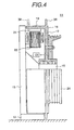
- Fig. 4 shows another embodiment of the present invention. What is different from the previously described embodiment is a peripheral shape of the rotating frame 16, and the same reference numbers as in Figs 1 to 3 denote the same parts, so that repeated explanation thereof is omitted.
- a disc 38 crossing the fixed shaft 15 at right angles is formed on extension of the bottom portion 17 of the peripheral wall 19 of the rotating frame 16 and a well-known electromagnetic disc brake (not shown) is arranged so as to sandwich the disc 38, whereby a hoisting machine 11 with electromagnetic disc brake can be provided.
- a disc 39 is formed on the opening side of the peripheral wall 19 of the rotating frame 16 and an electromagnetic disc brake (not shown) is arranged so as to oppose the disc 39, whereby the disc 39 becomes a reinforcing annular ring of thick thickness and it is possible to raise the rigidity of the peripheral wall 19 on the opening side, so that it is possible to make thin the thickness of the peripheral wall 19.
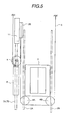
- FIGs. 5 and 6 show an optimum arrangement of device and apparatus inside the elevator shaft.
- the same reference numbers as in Figs. 1 to 3 denote the same parts and repeated explanation is omitted.
- a pair of cage guide rails 2A, 2B are vertically arranged at an interval on the both sides of the cages 3 in the width direction parallel with the cage door 3D. Further, guide pulleys 4A, 4B are supported by shaft on the bottom portion of the cage 3 at an interval in the same width direction, and the guide pulleys 4A, 4B are arranged on an opposite side to the cage door 3D with respect to the cage guide rails 2A, 2B.
- a pair of counterweight guide rails 7A, 7B are vertically arranged at an interval along the direction of inlet outlet of the cage 3 and guide to ascend and descend the counterweight 8. Further, the pair of counterweight guide rails 7A, 7B are arranged, viewed it on plane, on an opposite side to the cage door 3D with respect to the cage guide rail 2A.
- the guide pulley 9 On the upper portion of the counterweight 8, the guide pulley 9 is supported by shaft.
- the guide pulley 9 is arranged to incline against the interval direction of the counterweight guide rails 7A, 7B so that a diameter-directional end of the guide pulley 9 overlaps or is adjacent to the other diameter-directional end of the sheave 26.
- the counterweight 8, the respective guide pulleys 4A, 4B, 9 and the sheave 9 are arranged, so that they can be effectively installed in a narrow inside of the elevator shaft 1, and even if the hoisting machine is installed inside the elevator shaft 1, it is unnecessary to increase the area of the elevator shaft 1.
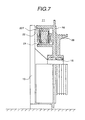
- the stator 22 is supported on the fixed frame 13 through a retaining member 22Y positioned on the outer diameter side of the stator 22, so that an outer diameter portion as the motor is an outer peripheral portion of the retaining member 22Y.
- a sheave of a hoisting machine used for an elevator apparatus is mounted on a rotating frame, which is one of rotating portion, supported by the fixed shaft.
- the motor of which the rotor is constituted on a rotating shaft is used for a hoisting machine, it also is considered to mount a sheave on the rotating shaft and fix it thereto, however, since the rotating shaft is small in diameter, it is troublesome in structure to detachably mount the sheave there, so that in such a case, it is necessary to detachably mount the sheave on a rotating portion of the motor other than the rotating shaft.
Landscapes
- Engineering & Computer Science (AREA)
- Civil Engineering (AREA)
- Mechanical Engineering (AREA)
- Structural Engineering (AREA)
- Cage And Drive Apparatuses For Elevators (AREA)
- Lift-Guide Devices, And Elevator Ropes And Cables (AREA)
Applications Claiming Priority (2)
| Application Number | Priority Date | Filing Date | Title |
|---|---|---|---|
| JP19123898A JP3725979B2 (ja) | 1998-07-07 | 1998-07-07 | エレベーター装置 |
| JP19123898 | 1998-07-07 |
Publications (4)
| Publication Number | Publication Date |
|---|---|
| EP0970912A2 EP0970912A2 (en) | 2000-01-12 |
| EP0970912A3 EP0970912A3 (en) | 2002-03-06 |
| EP0970912B1 EP0970912B1 (en) | 2004-11-03 |
| EP0970912B2 true EP0970912B2 (en) | 2007-08-08 |
Family
ID=16271207
Family Applications (1)
| Application Number | Title | Priority Date | Filing Date |
|---|---|---|---|
| EP99112612A Expired - Lifetime EP0970912B2 (en) | 1998-07-07 | 1999-07-01 | Elevator apparatus |
Country Status (4)
| Country | Link |
|---|---|
| EP (1) | EP0970912B2 (enExample) |
| JP (1) | JP3725979B2 (enExample) |
| CN (1) | CN1106338C (enExample) |
| DE (1) | DE69921555T3 (enExample) |
Families Citing this family (34)
| Publication number | Priority date | Publication date | Assignee | Title |
|---|---|---|---|---|
| JP2001226058A (ja) * | 2000-02-10 | 2001-08-21 | Mitsubishi Electric Corp | エレベータのドア装置 |
| ES2220798T5 (es) * | 2000-09-27 | 2010-05-12 | Inventio Ag | Ascensor con unidad motriz dispuesta lateralmente en la parte superior de la caja de ascensor. |
| JP2003106348A (ja) | 2001-09-28 | 2003-04-09 | Meidensha Corp | ブレーキ装置及び巻上機 |
| JP2003104666A (ja) | 2001-09-28 | 2003-04-09 | Meidensha Corp | 巻上機及びエレベータ装置 |
| IL180964A (en) | 2002-09-05 | 2010-11-30 | Inventio Ag | Drive engine for a lift installation and method of mounting a drive engine |
| KR100451317B1 (ko) * | 2002-09-17 | 2004-10-06 | 현대엘리베이터주식회사 | 엘리베이터용 박형 권상기 |
| FR2858723B1 (fr) * | 2003-08-08 | 2005-12-30 | Leroy Somer Moteurs | Machine electrique, notamment pour ascenseur |
| JP4439470B2 (ja) * | 2003-08-21 | 2010-03-24 | 三菱電機株式会社 | エレベータ用薄形巻上機 |
| WO2005068338A1 (ja) * | 2004-01-15 | 2005-07-28 | Mitsubishi Denki Kabushiki Kaisha | エレベータ用巻上機 |
| JP4525197B2 (ja) * | 2004-06-17 | 2010-08-18 | 株式会社明電舎 | エレベータ巻上機 |
| JP4292206B2 (ja) * | 2004-07-29 | 2009-07-08 | 三菱電機株式会社 | エレベーター用巻上機 |
| JP4365345B2 (ja) * | 2004-10-20 | 2009-11-18 | 三菱電機株式会社 | 巻上機及びその据付方法 |
| KR100705144B1 (ko) * | 2005-04-20 | 2007-04-09 | 미쓰비시덴키 가부시키가이샤 | 엘리베이터용 박형 권상기 |
| KR100703461B1 (ko) * | 2006-03-03 | 2007-04-03 | 미쓰비시덴키 가부시키가이샤 | 엘리베이터용 권상기 |
| DE102006052767B4 (de) * | 2006-11-09 | 2012-11-08 | Robert Bosch Gmbh | Außenläufermotor mit Bremse |
| JP5255785B2 (ja) * | 2007-06-15 | 2013-08-07 | 株式会社日立産機システム | エレベータ用巻上機 |
| JP5380837B2 (ja) * | 2007-12-27 | 2014-01-08 | 株式会社明電舎 | エレベータ用巻上機 |
| JP5458512B2 (ja) * | 2008-06-16 | 2014-04-02 | 株式会社明電舎 | 偏平形エレベータ用巻上機 |
| JP4900971B2 (ja) * | 2008-11-05 | 2012-03-21 | 東芝エレベータ株式会社 | エレベータシステム |
| JP2010193607A (ja) * | 2009-02-18 | 2010-09-02 | Mitsubishi Electric Corp | 回転電機及びその製造方法並びに巻上機 |
| JP5358282B2 (ja) * | 2009-05-14 | 2013-12-04 | 株式会社日立製作所 | エレベーター用巻上機、及び、エレベーター装置 |
| CN101987711B (zh) * | 2009-07-30 | 2013-02-13 | 包文丽 | 电梯用曳引机 |
| JP2011063434A (ja) * | 2009-09-18 | 2011-03-31 | Toshiba Elevator Co Ltd | エレベータ用巻上機のブレーキ装置および巻上機用ブレーキ装置の調整方法 |
| JP5048802B2 (ja) * | 2010-03-26 | 2012-10-17 | 株式会社日立製作所 | エレベータ用薄型巻上機、及びエレベータ装置 |
| JP2011241062A (ja) * | 2010-05-19 | 2011-12-01 | Hitachi Ltd | エレベーター装置 |
| CN102030245B (zh) * | 2010-12-31 | 2012-05-02 | 厦门康柏机械集团有限公司 | 倾斜式升降机吊笼 |
| JP5462195B2 (ja) * | 2011-01-25 | 2014-04-02 | 株式会社日立製作所 | エレベーター |
| WO2015186222A1 (ja) * | 2014-06-05 | 2015-12-10 | 三菱電機株式会社 | エレベータの巻上機、および、エレベータの巻上機の綱車の締結方法 |
| JP6180374B2 (ja) * | 2014-06-17 | 2017-08-16 | 三菱電機株式会社 | 回転体 |
| US10384914B2 (en) * | 2015-09-10 | 2019-08-20 | Otis Elevator Company | Elevator support structure |
| JP6134952B1 (ja) * | 2015-12-03 | 2017-05-31 | 株式会社明電舎 | 巻上機 |
| CN109850725B (zh) * | 2018-12-24 | 2023-11-21 | 菱王电梯有限公司 | 鼓式双支撑组合式高速重载曳引机 |
| WO2024185066A1 (ja) * | 2023-03-08 | 2024-09-12 | 株式会社日立製作所 | 機械室レスエレベーター |
| CN120004105B (zh) * | 2025-04-17 | 2025-07-04 | 上迅电梯(苏州)有限公司 | 一种电梯用曳引装置 |
Citations (3)
| Publication number | Priority date | Publication date | Assignee | Title |
|---|---|---|---|---|
| US4739969A (en) † | 1985-11-04 | 1988-04-26 | Johns Perry Industries Pty. Ltd. | Lift sheave |
| EP0676357A2 (en) † | 1994-04-07 | 1995-10-11 | Kone Oy | Elevator motor |
| EP0878430A2 (de) † | 1997-05-16 | 1998-11-18 | Baumüller Nürnberg Gmbh | Hebevorrichtung, insbesondere Aufzug, mit einem Elektromotor und Verwendung des Elektromotors |
Family Cites Families (8)
| Publication number | Priority date | Publication date | Assignee | Title |
|---|---|---|---|---|
| US1171964A (en) * | 1914-08-01 | 1916-02-15 | Alonso B Lee | Electric motor. |
| JPS63277190A (ja) * | 1987-05-07 | 1988-11-15 | 三菱電機株式会社 | エレベ−タ用巻上機 |
| JPH0745315B2 (ja) * | 1988-08-26 | 1995-05-17 | 三菱電機株式会社 | 巻上機 |
| FI114419B (fi) * | 1994-04-07 | 2004-10-15 | Kone Corp | Hissikoneisto |
| WO1995000432A1 (en) * | 1993-06-28 | 1995-01-05 | Kone Oy | Elevator machinery |
| DE19739001C1 (de) * | 1997-09-06 | 1998-10-15 | Ziehl Abegg Gmbh & Co Kg | Aufzugsantrieb mit elektrischem Antriebsmotor |
| EP0905081B1 (en) * | 1997-09-26 | 2003-01-08 | Kabushiki Kaisha Toshiba | Positioning of drive unit in an elevator shaft |
| DE19815962A1 (de) * | 1998-04-09 | 1999-10-14 | Atb Antriebstechnik Ag | Elektrische Maschine, insbesondere für Fahrstuhlantrieb |
-
1998
- 1998-07-07 JP JP19123898A patent/JP3725979B2/ja not_active Expired - Lifetime
-
1999
- 1999-06-30 CN CN99110155A patent/CN1106338C/zh not_active Expired - Fee Related
- 1999-07-01 EP EP99112612A patent/EP0970912B2/en not_active Expired - Lifetime
- 1999-07-01 DE DE1999621555 patent/DE69921555T3/de not_active Expired - Lifetime
Patent Citations (3)
| Publication number | Priority date | Publication date | Assignee | Title |
|---|---|---|---|---|
| US4739969A (en) † | 1985-11-04 | 1988-04-26 | Johns Perry Industries Pty. Ltd. | Lift sheave |
| EP0676357A2 (en) † | 1994-04-07 | 1995-10-11 | Kone Oy | Elevator motor |
| EP0878430A2 (de) † | 1997-05-16 | 1998-11-18 | Baumüller Nürnberg Gmbh | Hebevorrichtung, insbesondere Aufzug, mit einem Elektromotor und Verwendung des Elektromotors |
Non-Patent Citations (3)
| Title |
|---|
| Skriptum ''Heilbronner Aufzugstage 10. und 11. März 1998, Vortrag von Dr. Ralf Gfrörer ,,Antriebsvariante ohne Getriebe und ohne Triebwerksraum'' gemäss D2 Lift Report Seite 47/48 und 56. † |
| Zeitschrift ''Lift Report'' (1998), Heft 1 (Januar/Februar 1998), Seite 6 bis 13 † |
| Zeitschrift ''Lift Report'' (1998), Heft 3 ( Mai/Juni 1998), Seiten 46 bis 60. † |
Also Published As
| Publication number | Publication date |
|---|---|
| EP0970912A3 (en) | 2002-03-06 |
| DE69921555T3 (de) | 2008-03-06 |
| JP3725979B2 (ja) | 2005-12-14 |
| HK1023550A1 (en) | 2000-09-15 |
| JP2000016727A (ja) | 2000-01-18 |
| CN1106338C (zh) | 2003-04-23 |
| EP0970912A2 (en) | 2000-01-12 |
| CN1241528A (zh) | 2000-01-19 |
| DE69921555D1 (de) | 2004-12-09 |
| DE69921555T2 (de) | 2005-12-08 |
| EP0970912B1 (en) | 2004-11-03 |
Similar Documents
| Publication | Publication Date | Title |
|---|---|---|
| EP0970912B2 (en) | Elevator apparatus | |
| CN1037424C (zh) | 电梯装置 | |
| KR100314454B1 (ko) | 엘리베이터기계및그설비 | |
| US20040262090A1 (en) | Hoisting device for an elevator | |
| CN1050460C (zh) | 电梯机械 | |
| JPH11130365A (ja) | エレベータ装置 | |
| JPH06255959A (ja) | カウンタウエイト内に配置したエレベータモータ | |
| JPH08511758A (ja) | エレベータ機械装置 | |
| SG186575A1 (en) | Traction machine for elevator | |
| CN100545070C (zh) | 电梯用曳引机 | |
| JP2004338915A (ja) | エレベータ用巻上機 | |
| JP5048802B2 (ja) | エレベータ用薄型巻上機、及びエレベータ装置 | |
| JP2016124628A (ja) | 巻上機及びエレベータ | |
| KR100691663B1 (ko) | 엘리베이터의 구동장치 | |
| JP6915711B1 (ja) | 巻上機 | |
| EP1705148A1 (en) | Elevator hoist | |
| JP4284123B2 (ja) | 巻上機及び巻上機を備えたエレベーター装置 | |
| KR100441043B1 (ko) | 엘리베이터용 박형 권상기 | |
| JP3731599B2 (ja) | エレベータ装置 | |
| JP4032071B2 (ja) | エレベーター装置 | |
| JP3787570B2 (ja) | エレベーター装置 | |
| JP7261320B2 (ja) | 巻上機及びエレベーター | |
| JP2013028421A (ja) | 薄型巻上機およびエレベータ装置 | |
| JP2004075360A (ja) | エレベーター巻上機 | |
| KR100474217B1 (ko) | 엘리베이터용 박형 권상기의 고정자 구조 |
Legal Events
| Date | Code | Title | Description |
|---|---|---|---|
| PUAI | Public reference made under article 153(3) epc to a published international application that has entered the european phase |
Free format text: ORIGINAL CODE: 0009012 |
|
| AK | Designated contracting states |
Kind code of ref document: A2 Designated state(s): AT BE CH CY DE DK ES FI FR GB GR IE IT LI LU MC NL PT SE Kind code of ref document: A2 Designated state(s): DE FR |
|
| AX | Request for extension of the european patent |
Free format text: AL;LT;LV;MK;RO;SI |
|
| PUAL | Search report despatched |
Free format text: ORIGINAL CODE: 0009013 |
|
| AK | Designated contracting states |
Kind code of ref document: A3 Designated state(s): AT BE CH CY DE DK ES FI FR GB GR IE IT LI LU MC NL PT SE |
|
| AX | Request for extension of the european patent |
Free format text: AL;LT;LV;MK;RO;SI |
|
| 17P | Request for examination filed |
Effective date: 20020905 |
|
| AKX | Designation fees paid |
Free format text: DE FR |
|
| 17Q | First examination report despatched |
Effective date: 20021112 |
|
| GRAP | Despatch of communication of intention to grant a patent |
Free format text: ORIGINAL CODE: EPIDOSNIGR1 |
|
| GRAS | Grant fee paid |
Free format text: ORIGINAL CODE: EPIDOSNIGR3 |
|
| GRAA | (expected) grant |
Free format text: ORIGINAL CODE: 0009210 |
|
| AK | Designated contracting states |
Kind code of ref document: B1 Designated state(s): DE FR |
|
| REF | Corresponds to: |
Ref document number: 69921555 Country of ref document: DE Date of ref document: 20041209 Kind code of ref document: P |
|
| REG | Reference to a national code |
Ref country code: IE Ref legal event code: FG4D |
|
| PLBI | Opposition filed |
Free format text: ORIGINAL CODE: 0009260 |
|
| PLAX | Notice of opposition and request to file observation + time limit sent |
Free format text: ORIGINAL CODE: EPIDOSNOBS2 |
|
| 26 | Opposition filed |
Opponent name: ZIEHL-ABEGG AG Effective date: 20050722 |
|
| ET | Fr: translation filed | ||
| PLBB | Reply of patent proprietor to notice(s) of opposition received |
Free format text: ORIGINAL CODE: EPIDOSNOBS3 |
|
| PLAY | Examination report in opposition despatched + time limit |
Free format text: ORIGINAL CODE: EPIDOSNORE2 |
|
| PLBC | Reply to examination report in opposition received |
Free format text: ORIGINAL CODE: EPIDOSNORE3 |
|
| PUAH | Patent maintained in amended form |
Free format text: ORIGINAL CODE: 0009272 |
|
| STAA | Information on the status of an ep patent application or granted ep patent |
Free format text: STATUS: PATENT MAINTAINED AS AMENDED |
|
| 27A | Patent maintained in amended form |
Effective date: 20070808 |
|
| AK | Designated contracting states |
Kind code of ref document: B2 Designated state(s): DE FR |
|
| ET3 | Fr: translation filed ** decision concerning opposition | ||
| PLAB | Opposition data, opponent's data or that of the opponent's representative modified |
Free format text: ORIGINAL CODE: 0009299OPPO |
|
| PGFP | Annual fee paid to national office [announced via postgrant information from national office to epo] |
Ref country code: FR Payment date: 20140708 Year of fee payment: 16 |
|
| REG | Reference to a national code |
Ref country code: FR Ref legal event code: ST Effective date: 20160331 |
|
| PG25 | Lapsed in a contracting state [announced via postgrant information from national office to epo] |
Ref country code: FR Free format text: LAPSE BECAUSE OF NON-PAYMENT OF DUE FEES Effective date: 20150731 |
|
| PGFP | Annual fee paid to national office [announced via postgrant information from national office to epo] |
Ref country code: DE Payment date: 20160628 Year of fee payment: 18 |
|
| REG | Reference to a national code |
Ref country code: DE Ref legal event code: R119 Ref document number: 69921555 Country of ref document: DE |
|
| PG25 | Lapsed in a contracting state [announced via postgrant information from national office to epo] |
Ref country code: DE Free format text: LAPSE BECAUSE OF NON-PAYMENT OF DUE FEES Effective date: 20180201 |