EP0966083B1 - Enrouleur de câble automatique - Google Patents
Enrouleur de câble automatique Download PDFInfo
- Publication number
- EP0966083B1 EP0966083B1 EP99111275A EP99111275A EP0966083B1 EP 0966083 B1 EP0966083 B1 EP 0966083B1 EP 99111275 A EP99111275 A EP 99111275A EP 99111275 A EP99111275 A EP 99111275A EP 0966083 B1 EP0966083 B1 EP 0966083B1
- Authority
- EP
- European Patent Office
- Prior art keywords
- self
- cable reel
- baseplate
- reel according
- guide
- Prior art date
- Legal status (The legal status is an assumption and is not a legal conclusion. Google has not performed a legal analysis and makes no representation as to the accuracy of the status listed.)
- Expired - Lifetime
Links
Images

Classifications
-
- H—ELECTRICITY
- H02—GENERATION; CONVERSION OR DISTRIBUTION OF ELECTRIC POWER
- H02G—INSTALLATION OF ELECTRIC CABLES OR LINES, OR OF COMBINED OPTICAL AND ELECTRIC CABLES OR LINES
- H02G11/00—Arrangements of electric cables or lines between relatively-movable parts
- H02G11/02—Arrangements of electric cables or lines between relatively-movable parts using take-up reel or drum
-
- B—PERFORMING OPERATIONS; TRANSPORTING
- B65—CONVEYING; PACKING; STORING; HANDLING THIN OR FILAMENTARY MATERIAL
- B65H—HANDLING THIN OR FILAMENTARY MATERIAL, e.g. SHEETS, WEBS, CABLES
- B65H75/00—Storing webs, tapes, or filamentary material, e.g. on reels
- B65H75/02—Cores, formers, supports, or holders for coiled, wound, or folded material, e.g. reels, spindles, bobbins, cop tubes, cans, mandrels or chucks
- B65H75/34—Cores, formers, supports, or holders for coiled, wound, or folded material, e.g. reels, spindles, bobbins, cop tubes, cans, mandrels or chucks specially adapted or mounted for storing and repeatedly paying-out and re-storing lengths of material provided for particular purposes, e.g. anchored hoses, power cables
- B65H75/38—Cores, formers, supports, or holders for coiled, wound, or folded material, e.g. reels, spindles, bobbins, cop tubes, cans, mandrels or chucks specially adapted or mounted for storing and repeatedly paying-out and re-storing lengths of material provided for particular purposes, e.g. anchored hoses, power cables involving the use of a core or former internal to, and supporting, a stored package of material
- B65H75/44—Constructional details
- B65H75/4418—Arrangements for stopping winding or unwinding; Arrangements for releasing the stop means
- B65H75/4428—Arrangements for stopping winding or unwinding; Arrangements for releasing the stop means acting on the reel or on a reel blocking mechanism
- B65H75/4431—Manual stop or release button
Definitions
- the invention relates to a self-winding cable reel with a base plate on a trunnion receives the cable drum and an outer first peripheral wall and one in one Has radially aligned first ring wall.
- Such a cable reel is known from DE 40 25 409 C1.
- the cable drum formed in several parts and the arrangement of the functional parts such as rewind spring, brake and slip rings is complex.
- the object of the invention is a stable and concentrated structure of all functional parts on one Base plate and a contact arrangement made up of few individual parts.
- the invention differs from the prior art in that all functional parts of the Base plate are included, the braking forces of the brake roller and the tensile forces of the reel spring be transferred within the base plate to a circumferential socket of the cable drum, so that in Operation of the cable reel only low moments of force occur.
- the arrangement of the contact rings with molded plug pins or tabs on the base plate has the advantage that the contact rings can be easily exchanged if a different connection type is required, e.g. Flat plug in of a different thickness or of a different material.
- a secure reception and mounting of the reel spring is achieved in that the reel spring is attached to a central pin of the chamber.
- a uniform load on the slip rings is achieved by the two sliding contacts are of the same design and that the contact heads of the sliding contacts are approximately diametrically opposite one another.
- a stable design of the brake and easy accessibility are achieved in that the side of the base plate opposite the bearing journal provides a radial guide for a brake lever is provided and that the brake lever symmetrically aligned to the guide slots for guidance a pin of a brake roller.
- the brake can be mounted from the free side of the base plate and exchangeable at any time. This means that a defective brake can be quickly replaced.
- the bias of the brake lever in the braking position is ensured by the fact that one in the radial Direction effective compression spring between the brake lever and a radially aligned pin the base plate is supported.
- a retention and path limitation for the centrifugal weights is achieved in that radial guides of a flange of the cable drum guided centrifugal weights with slots Reach over locking elements of the guides.
- a simple and safe strain relief is achieved by the fact that within the core of the cable drum clamping strain relief elements are provided.
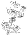
- the cable reel comprises the following main parts: a base plate 1 with a hollow bearing journal 2, a cable drum 3 with a hub 4 seated on the journal 2, a bush-shaped closure 5 with locking hooks 57 for holding the cable drum 3 or its hub 4 on the bearing journal 2, a in a chamber 6 of the base plate 1 roll 7 with a winding spring 8, one in one radial guide 27 of the base plate 2 received brake lever 9 with a compression spring 10 and Brake roller 11, and electrical functional parts such as two contact rings 12, 13 and two resilient sliding contacts 14, 15.
- the chamber 6 and the guide 27 are on the opposite of the journal 2 Side of the base plate 1 open. Centrifugal weights 16 are guided in a flange 36 of the cable drum 3 and held.
- the base plate 1 is the supporting component of the cable reel and is in a, not shown Housing installed and locked in place or held in some other way.
- the base plate 1 includes a outer jacket-shaped first peripheral wall 17, a first ring wall 18 aligned in a radial plane, a further jacket-shaped second peripheral wall 19, the two peripheral walls 17, 19 each in Connect opposite directions to the first ring wall 18, a second aligned in a radial plane Annular wall 20, an inner jacket-shaped third circumferential wall 21 with the second annular wall 20 and the second peripheral wall 19 forms a U-shaped channel, a third radial ring wall 22 and the central bearing pin 2 for the hub 4 of the cable drum 3.
- the circular chamber 6 On the side of the base plate 1 opposite the journal 2 is located in the area the first ring wall 18, the circular chamber 6, in the center of which a hollow pin 24 with the face Lugs 25 is formed.
- the wall of the chamber 6 touches the second peripheral wall 19. In the contact area there is a window in the second peripheral wall 19 and the wall of the chamber 6 26 trained.
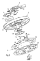
- a radially aligned, profiled guide 27 for the brake lever 9 for the brake lever 9, the Guide webs 50, locking lugs 51 and pins 52 in slots 29 or undercuts and recesses the guide 27 engages. Only one of the guide webs 50 and detents 51 is open one side of the brake lever 9 visible.
- the guide 27 On both sides of the guide 27 are in the inner third peripheral wall 21 window 28 formed for the brake roller 11, of which a window 28 for the one winding direction of the cable in Fig. 2 is visible. The other of these windows 28 is in the circumferential direction symmetrical to the slot 29 of the guide 27.
- a radial pin 31 aligned with the guide 27 for receiving the compression spring 10 formed.
- the brake lever 9 is inserted in the axial direction in the guide 27 and therein by the Guide bars 50 and latch 51 latched and biased by the compression spring 10 in the braking position and secured.
- the brake lever can be removed in the axial direction. It can therefore be damaged at any time be replaced.
- the two contact rings 12 and 13 are embedded, each one Wear plug pin or flat plug 33 and retaining tabs 34, which pass through the third ring wall 22 are inserted and hold the contact rings 12 and 13 and enable their electrical connection.
- Two flanges 36, 37 are seated on a coil core 35 of the cable drum 3 two pocket-shaped guides 38 formed for centrifugal weights 16. Locking elements 53 of each guide 38 engage in slots 54 of each centrifugal weight 16, so that the centrifugal weights 16 only over can move the braking distance predetermined by the slots 54.
- a circumferential socket 39 adjoins the coil core 35, in which the winding spring 8 is hooked in , which lies when the cable is pulled out around the circumferential connector 39, and its inner surface on the other hand, serves as a braking surface for the brake roller 11.
- a radially aligned ring wall 40 carries the hub 4, which on the Bearing journal 2 fits.
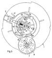
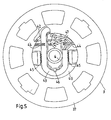
- the strain relief device is attached, how to 5 seen from the view.
- the connecting cable 43 is held by retaining webs 44, Jaws 45 and tabs 46 clamped and held in place.
- the conductor ends 47 have plug sleeves 48, which are plugged onto the plug pins or flat plugs 49 of the sliding contacts 14, 15.
- the Sliding contacts 14, 15 are held in the ring wall 40 and are biased with contact heads 55 on the contact rings 12, 13.
- the sliding contacts 14, 15 are of the same design.
- the contact heads 55 are approximately diametrically opposite each other, so that there is a uniform contact pressure on the Contact rings 12, 13 results.
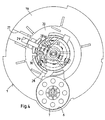
- the brake lever 9 engages with the guide webs 50, the guide lugs 51 and the guide pins 52 in slots 29 and other guides of the base plate 1. As a result, the brake lever 9 is radial Direction.
- the compression spring 10 is supported on the pin 31 of the base plate 1 and on the Brake lever 9 and biases the brake lever 9 in the braking position.
- Each in a slot 56 of the Brake lever 9 is a pin 58 of the brake roller 11 out.
- the slots 56 are against each other and against the walls 30 inclined. In the braking position, pulling out the connection cable is possible, however the cable drum 3 is braked by the brake roller 11 and thus the winding spring 8 is ineffective.
- the Brake roller is released by actuating the brake lever 9 against the spring tension, so that the winding spring 8 can take effect.
Landscapes
- Storing, Repeated Paying-Out, And Re-Storing Of Elongated Articles (AREA)
- Storage Of Web-Like Or Filamentary Materials (AREA)
- Braking Arrangements (AREA)
- Unwinding Of Filamentary Materials (AREA)
Claims (9)
- Enrouleur de câble. automatique, avec une plaque de base (1), qui porte un tambour de câble (3) sur un tourillon (2) et qui présente une première paroi périphérique extérieure (17) ainsi qu'une première paroi annulaire (18) orientée dans un plan radial, caractérisé en ce qu'un appui périphérique (39) du tambour de câble (3) pénètre dans une gorge en U de la plaque de base (1), formée par une deuxième paroi périphérique (19), une deuxième paroi annulaire (20) et une troisième paroi périphérique (21), en ce qu'une chambre (6) de la plaque de base (1) se raccorde à une fenêtre (26) de la deuxième paroi périphérique (19) et contient un ressort d'enroulement (8), qui est fixé à l'appui périphérique (39), en ce que la troisième paroi périphérique (21) présente au moins une fenêtre supplémentaire (28), à travers laquelle un galet de frein (11) passe et s'applique sur la surface intérieure de l'appui périphérique (39), en ce qu'une paroi annulaire centrale (22) de la plaque de base (1) comporte des bagues de contact (12, 13) et porte un tourillon (2) et en ce qu'une paroi annulaire (40) du tambour de câble (3) porte des contacts glissants (14, 15).
- Enrouleur de câble automatique suivant la revendication 1, caractérisé en ce que le ressort d'enroulement (8) est fixé sur un tourillon central (24) de la chambre (6).
- Enrouleur de câble automatique suivant la revendication 1 ou 2, caractérisé en ce que les deux contacts glissants (14, 15) sont de configuration identique et en ce que les têtes de contact (55) des contacts glissants sont sensiblement diamétralement opposées l'une à l'autre.
- Enrouleur de câble automatique suivant la revendication 3, caractérisé en ce que les bagues de contact (12, 13) sont interchangeables et présentent des broches de contact (33), respectivement des fiches plates.
- Enrouleur de câble automatique suivant l'une quelconque des revendications 1 à 5, caractérisé en ce qu'il est prévu, sur le côté de la plaque de base (1) situé à l'opposé du tourillon (2), un guidage radial (27) pour un levier de frein (9) et en ce que le levier de frein (9) présente des fentes (56) orientées symétriquement au guidage (27) pour le guidage d'un tourillon (58) d'un galet de frein (11).
- Enrouleur de câble automatique suivant la revendication 5, caractérisé en ce que le levier de frein (9) peut être poussé en direction axiale dans le guidage (27) et dans la plaque de base (1) et en ce qu'il peut être verrouillé par des nervures de guidage (50) et des ergots d'arrêt (51).
- Enrouleur de câble automatique suivant la revendication 5 ou 6, caractérisé en ce qu'un ressort de pression (10) agissant en direction radiale prend appui entre le levier de frein (9) et un tenon (31) de la plaque de base (1) orienté en direction radiale.
- Enrouleur de câble automatique suivant l'une quelconque des revendications 1 à 7, caractérisé en ce que des poids volants (16), guidés dans des guidages radiaux (38) d'un flasque (36) du tambour de câble (3), s'accrochent par des fentes (54) à des éléments d'arrêt (53) des guidages (38).
- Enrouleur de câble automatique suivant l'une quelconque des revendications 1 à 8, caractérisé en ce qu'il est prévu des éléments de détente de la traction se bloquant à l'intérieur du noyau du tambour de câble.
Priority Applications (1)
| Application Number | Priority Date | Filing Date | Title |
|---|---|---|---|
| SI9930153T SI0966083T1 (en) | 1998-06-16 | 1999-06-10 | Automatic cable winding device |
Applications Claiming Priority (2)
| Application Number | Priority Date | Filing Date | Title |
|---|---|---|---|
| DE19826661 | 1998-06-16 | ||
| DE19826661A DE19826661C1 (de) | 1998-06-16 | 1998-06-16 | Selbstaufwickelnder Kabelaufroller |
Publications (3)
| Publication Number | Publication Date |
|---|---|
| EP0966083A2 EP0966083A2 (fr) | 1999-12-22 |
| EP0966083A3 EP0966083A3 (fr) | 2000-09-20 |
| EP0966083B1 true EP0966083B1 (fr) | 2002-10-09 |
Family
ID=7870970
Family Applications (1)
| Application Number | Title | Priority Date | Filing Date |
|---|---|---|---|
| EP99111275A Expired - Lifetime EP0966083B1 (fr) | 1998-06-16 | 1999-06-10 | Enrouleur de câble automatique |
Country Status (11)
| Country | Link |
|---|---|
| US (1) | US6179104B1 (fr) |
| EP (1) | EP0966083B1 (fr) |
| DE (1) | DE19826661C1 (fr) |
| DK (1) | DK0966083T3 (fr) |
| ES (1) | ES2185272T3 (fr) |
| HU (1) | HU222932B1 (fr) |
| PL (1) | PL188249B1 (fr) |
| PT (1) | PT966083E (fr) |
| SI (1) | SI0966083T1 (fr) |
| SK (1) | SK284156B6 (fr) |
| TR (1) | TR199901324A2 (fr) |
Cited By (1)
| Publication number | Priority date | Publication date | Assignee | Title |
|---|---|---|---|---|
| CN100583583C (zh) * | 2008-08-18 | 2010-01-20 | 北京星光影视设备科技股份有限公司 | 无触点随动电缆卷筒装置 |
Families Citing this family (21)
| Publication number | Priority date | Publication date | Assignee | Title |
|---|---|---|---|---|
| DE20008014U1 (de) * | 2000-05-05 | 2000-08-03 | Mueller Roland | Wickelleine für Tiere |
| DE10142110A1 (de) * | 2001-08-30 | 2003-03-20 | Bsh Bosch Siemens Hausgeraete | Kabeltrommel |
| KR200306552Y1 (ko) * | 2002-11-29 | 2003-03-11 | 두얼메카닉스 주식회사 | 권취장치 |
| US7987552B2 (en) * | 2004-11-17 | 2011-08-02 | Techtronic Floor Care Technology Limited | Floor care appliance with a plurality of cleaning modes |
| US7419038B2 (en) * | 2005-05-31 | 2008-09-02 | Great Stuff, Inc. | Reel and reel housing |
| DE102006018618B4 (de) * | 2006-04-21 | 2008-02-14 | Oligo Lichttechnik Gmbh | Kabelaufroller und Verwendung desselben |
| US8723498B2 (en) * | 2008-12-19 | 2014-05-13 | Hewlett-Packard Development Company, L.P. | Systems and methods of increasing power measurement accuracy for power factor correction |
| US8167102B2 (en) * | 2009-08-13 | 2012-05-01 | Hewlett-Packard Development Company, L.P. | Cable spool for carrying connectivity cable for mobile computing devices |
| US8985541B2 (en) * | 2010-06-11 | 2015-03-24 | Sennco Solutions | Cable roller, system and/or method for extending and/or retracting a coiled cable |
| US8878397B2 (en) | 2010-08-31 | 2014-11-04 | Great Stuff, Inc. | Electrical cord reel with control system to limit overheating |
| US20120091249A1 (en) | 2010-10-19 | 2012-04-19 | John Mezzalingua Associates, Inc. | Cable carrying case |
| CN202245570U (zh) * | 2010-12-17 | 2012-05-30 | 太仓阿托斯电气部件有限公司 | 卷线器的刹车结构 |
| CN102556776B (zh) | 2010-12-17 | 2015-01-14 | 太仓阿托斯电气部件有限公司 | 卷线器的刹车结构 |
| US20130168486A1 (en) * | 2011-10-25 | 2013-07-04 | Tony Abfall | System and Method for Protection and Storage of Small Electronic Components |
| DE102011086809B4 (de) | 2011-11-22 | 2017-08-10 | BSH Hausgeräte GmbH | Kabeltrommel und diese umfassendes elektrisches Gerät |
| CN103922200A (zh) * | 2014-03-14 | 2014-07-16 | 苏州亚都环保科技有限公司 | 一种收线装置 |
| CN104528480B (zh) * | 2014-12-26 | 2017-02-22 | 市下控股有限公司 | 卷管器的自动回缩减速装置 |
| CN104934809B (zh) * | 2015-04-23 | 2017-06-23 | 宁波德昌电机制造有限公司 | 一种具有连续自动收线能力的卷线装置 |
| KR20210121786A (ko) * | 2020-03-31 | 2021-10-08 | 주식회사 엘지에너지솔루션 | 이종금속으로 이루어진 hv 버스 바 및 이의 제조 방법 |
| CN111799704B (zh) * | 2020-07-20 | 2021-09-28 | 宁夏同润华盛建设工程有限公司 | 一种水利水电工程用可分类的埋线装置 |
| DE202023100852U1 (de) | 2023-02-23 | 2023-03-29 | Athos Holding Gmbh | Kabelaufroller |
Family Cites Families (10)
| Publication number | Priority date | Publication date | Assignee | Title |
|---|---|---|---|---|
| US2856470A (en) * | 1956-07-20 | 1958-10-14 | Stanley R Hyde | Extension cord assembly |
| US3208121A (en) * | 1963-10-03 | 1965-09-28 | James C Price | Storage reel |
| US3680809A (en) * | 1970-01-05 | 1972-08-01 | Wanskuck Co | Reel |
| US3657491A (en) * | 1970-05-28 | 1972-04-18 | Illinois Tool Works | Cord reel |
| NL7602589A (nl) * | 1976-03-12 | 1977-09-14 | Draka Kabel Bv | Snoerhaspel. |
| DE3039202A1 (de) * | 1980-10-17 | 1982-05-13 | Kabel- und Metallwerke Gutehoffnungshütte AG, 3000 Hannover | Vorrichtung zum selbsttaetigen aufwickeln einer elektrischen leitung auf eine spule |
| DE8532395U1 (de) * | 1985-11-15 | 1986-07-24 | Siemens AG, 1000 Berlin und 8000 München | Kabelaufrollvorrichtung |
| DE3813824A1 (de) * | 1988-04-23 | 1989-11-02 | Miele & Cie | Gleichlaufbremse, insbesondere fuer eine einbau-kabeltrommel eines staubsaugers |
| DE4025409C1 (en) * | 1990-08-10 | 1991-11-28 | Atlanta-Kabel-Steinmueller Kg, 5880 Luedenscheid, De | Cable roller for drum - has slip-rings separated by insulating spacers from hub |
| US5261514A (en) * | 1992-05-04 | 1993-11-16 | Woodhead Industries, Inc. | Grounding cable reel for vehicle |
-
1998
- 1998-06-16 DE DE19826661A patent/DE19826661C1/de not_active Expired - Lifetime
-
1999
- 1999-06-03 US US09/325,097 patent/US6179104B1/en not_active Expired - Lifetime
- 1999-06-10 SI SI9930153T patent/SI0966083T1/xx unknown
- 1999-06-10 EP EP99111275A patent/EP0966083B1/fr not_active Expired - Lifetime
- 1999-06-10 ES ES99111275T patent/ES2185272T3/es not_active Expired - Lifetime
- 1999-06-10 PT PT99111275T patent/PT966083E/pt unknown
- 1999-06-10 DK DK99111275T patent/DK0966083T3/da active
- 1999-06-11 PL PL99333699A patent/PL188249B1/pl not_active IP Right Cessation
- 1999-06-14 TR TR1999/01324A patent/TR199901324A2/xx unknown
- 1999-06-14 SK SK797-99A patent/SK284156B6/sk unknown
- 1999-06-16 HU HU9902008A patent/HU222932B1/hu not_active IP Right Cessation
Cited By (1)
| Publication number | Priority date | Publication date | Assignee | Title |
|---|---|---|---|---|
| CN100583583C (zh) * | 2008-08-18 | 2010-01-20 | 北京星光影视设备科技股份有限公司 | 无触点随动电缆卷筒装置 |
Also Published As
| Publication number | Publication date |
|---|---|
| TR199901324A3 (tr) | 2000-01-21 |
| TR199901324A2 (xx) | 2000-01-21 |
| PL188249B1 (pl) | 2005-01-31 |
| HUP9902008A2 (hu) | 2000-05-28 |
| PT966083E (pt) | 2003-02-28 |
| HUP9902008A3 (en) | 2002-06-28 |
| HU222932B1 (hu) | 2003-12-29 |
| HU9902008D0 (en) | 1999-08-30 |
| EP0966083A2 (fr) | 1999-12-22 |
| PL333699A1 (en) | 1999-12-20 |
| ES2185272T3 (es) | 2003-04-16 |
| DK0966083T3 (da) | 2003-02-10 |
| US6179104B1 (en) | 2001-01-30 |
| EP0966083A3 (fr) | 2000-09-20 |
| SI0966083T1 (en) | 2003-04-30 |
| SK79799A3 (en) | 2000-01-18 |
| SK284156B6 (sk) | 2004-10-05 |
| DE19826661C1 (de) | 1999-10-21 |
Similar Documents
| Publication | Publication Date | Title |
|---|---|---|
| EP0966083B1 (fr) | Enrouleur de câble automatique | |
| DE602004009557T2 (de) | Aufwickelkabelhaspel zur verwendung mit elektrischem flachkabel | |
| DE2711100C3 (de) | Rollbandmaß | |
| DE2126011A1 (de) | Kabeltrommel | |
| DE19635236C1 (de) | Gewichtsausgleichsvorrichtung, insbesondere für eine medizinische Röntgeneinrichtung | |
| DE19747393C2 (de) | Gewichtsausgleichsvorrichtung, insbesondere für ein medizintechnisches Gerät | |
| DE19505926A1 (de) | Kabeltrommel | |
| DE19852975C2 (de) | Spannungsreduzierer zum Entlasten der Zugkraft einer Aufrollvorrichtung für einen Sicherheitsgurt | |
| DE2756023C3 (de) | Kabelaufrollvorrichtung mit einer Kabeltrommel | |
| DE3042185C2 (fr) | ||
| DE102008057223A1 (de) | Vorrichtung zum Überwachen des Zustandes einer Schutzeinrichtung einer Maschine | |
| DE2824330C3 (de) | Spulenanordnung für Bandgeräte | |
| EP0149072B1 (fr) | Tambour de câble portatif | |
| DE102004008328B4 (de) | Selbstaufwickelnde Kabeltrommel | |
| DE3339977C2 (fr) | ||
| EP0124823B1 (fr) | Dispositif enrouleur pour matériau filiforme | |
| EP1784109B1 (fr) | Enrouleur de câble presentant un flasque d'enrouleur ne comprenant pas de palier et pourvu d'une butée | |
| EP0099048B1 (fr) | Tambour pour câble | |
| EP0517083B1 (fr) | Dispositif d'enroulement de matériaux filiformes | |
| DE102004002850B4 (de) | Elektrischer Steckverbinder | |
| EP2193232A1 (fr) | Machine à laver | |
| DE3303879C2 (fr) | ||
| DE112017007993T5 (de) | Rückwärtsantriebssperrkupplung | |
| DE1574391B2 (de) | Kabelwinde, insbesondere zum einbau in haushaltsgeraete | |
| EP1157451B1 (fr) | Dispositif de contacts a frottement pour enrouleurs de cables |
Legal Events
| Date | Code | Title | Description |
|---|---|---|---|
| PUAI | Public reference made under article 153(3) epc to a published international application that has entered the european phase |
Free format text: ORIGINAL CODE: 0009012 |
|
| AK | Designated contracting states |
Kind code of ref document: A2 Designated state(s): DK ES FR GB IE IT NL PT SE |
|
| AX | Request for extension of the european patent |
Free format text: AL;LT;LV;MK;RO;SI |
|
| PUAL | Search report despatched |
Free format text: ORIGINAL CODE: 0009013 |
|
| AK | Designated contracting states |
Kind code of ref document: A3 Designated state(s): AT BE CH CY DE DK ES FI FR GB GR IE IT LI LU MC NL PT SE |
|
| AX | Request for extension of the european patent |
Free format text: AL;LT;LV;MK;RO;SI |
|
| 17P | Request for examination filed |
Effective date: 20010307 |
|
| 17Q | First examination report despatched |
Effective date: 20010411 |
|
| AKX | Designation fees paid |
Free format text: DK ES FR GB IE IT NL PT SE |
|
| REG | Reference to a national code |
Ref country code: DE Ref legal event code: 8566 |
|
| RAX | Requested extension states of the european patent have changed |
Free format text: SI PAYMENT 20010320 |
|
| GRAG | Despatch of communication of intention to grant |
Free format text: ORIGINAL CODE: EPIDOS AGRA |
|
| GRAG | Despatch of communication of intention to grant |
Free format text: ORIGINAL CODE: EPIDOS AGRA |
|
| GRAH | Despatch of communication of intention to grant a patent |
Free format text: ORIGINAL CODE: EPIDOS IGRA |
|
| GRAH | Despatch of communication of intention to grant a patent |
Free format text: ORIGINAL CODE: EPIDOS IGRA |
|
| GRAA | (expected) grant |
Free format text: ORIGINAL CODE: 0009210 |
|
| GRAH | Despatch of communication of intention to grant a patent |
Free format text: ORIGINAL CODE: EPIDOS IGRA |
|
| AK | Designated contracting states |
Kind code of ref document: B1 Designated state(s): DK ES FR GB IE IT NL PT SE |
|
| AX | Request for extension of the european patent |
Free format text: SI PAYMENT 20010320 |
|
| REG | Reference to a national code |
Ref country code: GB Ref legal event code: FG4D Free format text: NOT ENGLISH |
|
| REG | Reference to a national code |
Ref country code: IE Ref legal event code: FG4D Free format text: GERMAN |
|
| GBT | Gb: translation of ep patent filed (gb section 77(6)(a)/1977) |
Effective date: 20021206 |
|
| ET | Fr: translation filed | ||
| REG | Reference to a national code |
Ref country code: DK Ref legal event code: T3 |
|
| REG | Reference to a national code |
Ref country code: PT Ref legal event code: SC4A Free format text: AVAILABILITY OF NATIONAL TRANSLATION Effective date: 20030108 |
|
| REG | Reference to a national code |
Ref country code: ES Ref legal event code: FG2A Ref document number: 2185272 Country of ref document: ES Kind code of ref document: T3 |
|
| PLBE | No opposition filed within time limit |
Free format text: ORIGINAL CODE: 0009261 |
|
| STAA | Information on the status of an ep patent application or granted ep patent |
Free format text: STATUS: NO OPPOSITION FILED WITHIN TIME LIMIT |
|
| 26N | No opposition filed |
Effective date: 20030710 |
|
| PGFP | Annual fee paid to national office [announced via postgrant information from national office to epo] |
Ref country code: DK Payment date: 20040622 Year of fee payment: 6 |
|
| PGFP | Annual fee paid to national office [announced via postgrant information from national office to epo] |
Ref country code: SE Payment date: 20040623 Year of fee payment: 6 Ref country code: PT Payment date: 20040623 Year of fee payment: 6 |
|
| PGFP | Annual fee paid to national office [announced via postgrant information from national office to epo] |
Ref country code: IE Payment date: 20040628 Year of fee payment: 6 |
|
| REG | Reference to a national code |
Ref country code: SI Ref legal event code: IF |
|
| PG25 | Lapsed in a contracting state [announced via postgrant information from national office to epo] |
Ref country code: IE Free format text: LAPSE BECAUSE OF NON-PAYMENT OF DUE FEES Effective date: 20050610 |
|
| PG25 | Lapsed in a contracting state [announced via postgrant information from national office to epo] |
Ref country code: SE Free format text: LAPSE BECAUSE OF NON-PAYMENT OF DUE FEES Effective date: 20050611 |
|
| PG25 | Lapsed in a contracting state [announced via postgrant information from national office to epo] |
Ref country code: DK Free format text: LAPSE BECAUSE OF NON-PAYMENT OF DUE FEES Effective date: 20050630 |
|
| PG25 | Lapsed in a contracting state [announced via postgrant information from national office to epo] |
Ref country code: PT Free format text: LAPSE BECAUSE OF NON-PAYMENT OF DUE FEES Effective date: 20051212 |
|
| EUG | Se: european patent has lapsed | ||
| REG | Reference to a national code |
Ref country code: DK Ref legal event code: EBP |
|
| REG | Reference to a national code |
Ref country code: IE Ref legal event code: MM4A |
|
| REG | Reference to a national code |
Ref country code: SI Ref legal event code: SP73 Owner name: ATHOS HOLDING GMBH; DE Effective date: 20110812 |
|
| PGFP | Annual fee paid to national office [announced via postgrant information from national office to epo] |
Ref country code: NL Payment date: 20120628 Year of fee payment: 14 |
|
| PGFP | Annual fee paid to national office [announced via postgrant information from national office to epo] |
Ref country code: FR Payment date: 20120705 Year of fee payment: 14 Ref country code: GB Payment date: 20120621 Year of fee payment: 14 |
|
| PGFP | Annual fee paid to national office [announced via postgrant information from national office to epo] |
Ref country code: IT Payment date: 20120623 Year of fee payment: 14 |
|
| PGFP | Annual fee paid to national office [announced via postgrant information from national office to epo] |
Ref country code: ES Payment date: 20120628 Year of fee payment: 14 |
|
| REG | Reference to a national code |
Ref country code: NL Ref legal event code: V1 Effective date: 20140101 |
|
| GBPC | Gb: european patent ceased through non-payment of renewal fee |
Effective date: 20130610 |
|
| REG | Reference to a national code |
Ref country code: FR Ref legal event code: ST Effective date: 20140228 |
|
| REG | Reference to a national code |
Ref country code: SI Ref legal event code: KO00 Effective date: 20140225 |
|
| PG25 | Lapsed in a contracting state [announced via postgrant information from national office to epo] |
Ref country code: GB Free format text: LAPSE BECAUSE OF NON-PAYMENT OF DUE FEES Effective date: 20130610 Ref country code: NL Free format text: LAPSE BECAUSE OF NON-PAYMENT OF DUE FEES Effective date: 20140101 |
|
| PG25 | Lapsed in a contracting state [announced via postgrant information from national office to epo] |
Ref country code: IT Free format text: LAPSE BECAUSE OF NON-PAYMENT OF DUE FEES Effective date: 20130610 Ref country code: FR Free format text: LAPSE BECAUSE OF NON-PAYMENT OF DUE FEES Effective date: 20130701 |
|
| REG | Reference to a national code |
Ref country code: ES Ref legal event code: FD2A Effective date: 20150710 |
|
| PG25 | Lapsed in a contracting state [announced via postgrant information from national office to epo] |
Ref country code: ES Free format text: LAPSE BECAUSE OF NON-PAYMENT OF DUE FEES Effective date: 20130611 |