EP0966083B1 - Automatic cable winding device - Google Patents
Automatic cable winding device Download PDFInfo
- Publication number
- EP0966083B1 EP0966083B1 EP99111275A EP99111275A EP0966083B1 EP 0966083 B1 EP0966083 B1 EP 0966083B1 EP 99111275 A EP99111275 A EP 99111275A EP 99111275 A EP99111275 A EP 99111275A EP 0966083 B1 EP0966083 B1 EP 0966083B1
- Authority
- EP
- European Patent Office
- Prior art keywords
- self
- cable reel
- baseplate
- reel according
- guide
- Prior art date
- Legal status (The legal status is an assumption and is not a legal conclusion. Google has not performed a legal analysis and makes no representation as to the accuracy of the status listed.)
- Expired - Lifetime
Links
Images

Classifications
-
- H—ELECTRICITY
- H02—GENERATION; CONVERSION OR DISTRIBUTION OF ELECTRIC POWER
- H02G—INSTALLATION OF ELECTRIC CABLES OR LINES, OR OF COMBINED OPTICAL AND ELECTRIC CABLES OR LINES
- H02G11/00—Arrangements of electric cables or lines between relatively-movable parts
- H02G11/02—Arrangements of electric cables or lines between relatively-movable parts using take-up reel or drum
-
- B—PERFORMING OPERATIONS; TRANSPORTING
- B65—CONVEYING; PACKING; STORING; HANDLING THIN OR FILAMENTARY MATERIAL
- B65H—HANDLING THIN OR FILAMENTARY MATERIAL, e.g. SHEETS, WEBS, CABLES
- B65H75/00—Storing webs, tapes, or filamentary material, e.g. on reels
- B65H75/02—Cores, formers, supports, or holders for coiled, wound, or folded material, e.g. reels, spindles, bobbins, cop tubes, cans, mandrels or chucks
- B65H75/34—Cores, formers, supports, or holders for coiled, wound, or folded material, e.g. reels, spindles, bobbins, cop tubes, cans, mandrels or chucks specially adapted or mounted for storing and repeatedly paying-out and re-storing lengths of material provided for particular purposes, e.g. anchored hoses, power cables
- B65H75/38—Cores, formers, supports, or holders for coiled, wound, or folded material, e.g. reels, spindles, bobbins, cop tubes, cans, mandrels or chucks specially adapted or mounted for storing and repeatedly paying-out and re-storing lengths of material provided for particular purposes, e.g. anchored hoses, power cables involving the use of a core or former internal to, and supporting, a stored package of material
- B65H75/44—Constructional details
- B65H75/4418—Arrangements for stopping winding or unwinding; Arrangements for releasing the stop means
- B65H75/4428—Arrangements for stopping winding or unwinding; Arrangements for releasing the stop means acting on the reel or on a reel blocking mechanism
- B65H75/4431—Manual stop or release button
Definitions
- the invention relates to a self-winding cable reel with a base plate on a trunnion receives the cable drum and an outer first peripheral wall and one in one Has radially aligned first ring wall.
- Such a cable reel is known from DE 40 25 409 C1.
- the cable drum formed in several parts and the arrangement of the functional parts such as rewind spring, brake and slip rings is complex.
- the object of the invention is a stable and concentrated structure of all functional parts on one Base plate and a contact arrangement made up of few individual parts.
- the invention differs from the prior art in that all functional parts of the Base plate are included, the braking forces of the brake roller and the tensile forces of the reel spring be transferred within the base plate to a circumferential socket of the cable drum, so that in Operation of the cable reel only low moments of force occur.
- the arrangement of the contact rings with molded plug pins or tabs on the base plate has the advantage that the contact rings can be easily exchanged if a different connection type is required, e.g. Flat plug in of a different thickness or of a different material.
- a secure reception and mounting of the reel spring is achieved in that the reel spring is attached to a central pin of the chamber.
- a uniform load on the slip rings is achieved by the two sliding contacts are of the same design and that the contact heads of the sliding contacts are approximately diametrically opposite one another.
- a stable design of the brake and easy accessibility are achieved in that the side of the base plate opposite the bearing journal provides a radial guide for a brake lever is provided and that the brake lever symmetrically aligned to the guide slots for guidance a pin of a brake roller.
- the brake can be mounted from the free side of the base plate and exchangeable at any time. This means that a defective brake can be quickly replaced.
- the bias of the brake lever in the braking position is ensured by the fact that one in the radial Direction effective compression spring between the brake lever and a radially aligned pin the base plate is supported.
- a retention and path limitation for the centrifugal weights is achieved in that radial guides of a flange of the cable drum guided centrifugal weights with slots Reach over locking elements of the guides.
- a simple and safe strain relief is achieved by the fact that within the core of the cable drum clamping strain relief elements are provided.
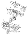
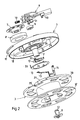
- the cable reel comprises the following main parts: a base plate 1 with a hollow bearing journal 2, a cable drum 3 with a hub 4 seated on the journal 2, a bush-shaped closure 5 with locking hooks 57 for holding the cable drum 3 or its hub 4 on the bearing journal 2, a in a chamber 6 of the base plate 1 roll 7 with a winding spring 8, one in one radial guide 27 of the base plate 2 received brake lever 9 with a compression spring 10 and Brake roller 11, and electrical functional parts such as two contact rings 12, 13 and two resilient sliding contacts 14, 15.
- the chamber 6 and the guide 27 are on the opposite of the journal 2 Side of the base plate 1 open. Centrifugal weights 16 are guided in a flange 36 of the cable drum 3 and held.
- the base plate 1 is the supporting component of the cable reel and is in a, not shown Housing installed and locked in place or held in some other way.
- the base plate 1 includes a outer jacket-shaped first peripheral wall 17, a first ring wall 18 aligned in a radial plane, a further jacket-shaped second peripheral wall 19, the two peripheral walls 17, 19 each in Connect opposite directions to the first ring wall 18, a second aligned in a radial plane Annular wall 20, an inner jacket-shaped third circumferential wall 21 with the second annular wall 20 and the second peripheral wall 19 forms a U-shaped channel, a third radial ring wall 22 and the central bearing pin 2 for the hub 4 of the cable drum 3.
- the circular chamber 6 On the side of the base plate 1 opposite the journal 2 is located in the area the first ring wall 18, the circular chamber 6, in the center of which a hollow pin 24 with the face Lugs 25 is formed.
- the wall of the chamber 6 touches the second peripheral wall 19. In the contact area there is a window in the second peripheral wall 19 and the wall of the chamber 6 26 trained.
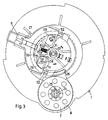
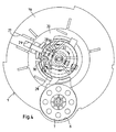
- a radially aligned, profiled guide 27 for the brake lever 9 for the brake lever 9, the Guide webs 50, locking lugs 51 and pins 52 in slots 29 or undercuts and recesses the guide 27 engages. Only one of the guide webs 50 and detents 51 is open one side of the brake lever 9 visible.
- the guide 27 On both sides of the guide 27 are in the inner third peripheral wall 21 window 28 formed for the brake roller 11, of which a window 28 for the one winding direction of the cable in Fig. 2 is visible. The other of these windows 28 is in the circumferential direction symmetrical to the slot 29 of the guide 27.
- a radial pin 31 aligned with the guide 27 for receiving the compression spring 10 formed.
- the brake lever 9 is inserted in the axial direction in the guide 27 and therein by the Guide bars 50 and latch 51 latched and biased by the compression spring 10 in the braking position and secured.
- the brake lever can be removed in the axial direction. It can therefore be damaged at any time be replaced.
- the two contact rings 12 and 13 are embedded, each one Wear plug pin or flat plug 33 and retaining tabs 34, which pass through the third ring wall 22 are inserted and hold the contact rings 12 and 13 and enable their electrical connection.
- Two flanges 36, 37 are seated on a coil core 35 of the cable drum 3 two pocket-shaped guides 38 formed for centrifugal weights 16. Locking elements 53 of each guide 38 engage in slots 54 of each centrifugal weight 16, so that the centrifugal weights 16 only over can move the braking distance predetermined by the slots 54.
- a circumferential socket 39 adjoins the coil core 35, in which the winding spring 8 is hooked in , which lies when the cable is pulled out around the circumferential connector 39, and its inner surface on the other hand, serves as a braking surface for the brake roller 11.
- a radially aligned ring wall 40 carries the hub 4, which on the Bearing journal 2 fits.
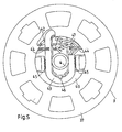
- the strain relief device is attached, how to 5 seen from the view.
- the connecting cable 43 is held by retaining webs 44, Jaws 45 and tabs 46 clamped and held in place.
- the conductor ends 47 have plug sleeves 48, which are plugged onto the plug pins or flat plugs 49 of the sliding contacts 14, 15.
- the Sliding contacts 14, 15 are held in the ring wall 40 and are biased with contact heads 55 on the contact rings 12, 13.
- the sliding contacts 14, 15 are of the same design.
- the contact heads 55 are approximately diametrically opposite each other, so that there is a uniform contact pressure on the Contact rings 12, 13 results.
- the brake lever 9 engages with the guide webs 50, the guide lugs 51 and the guide pins 52 in slots 29 and other guides of the base plate 1. As a result, the brake lever 9 is radial Direction.
- the compression spring 10 is supported on the pin 31 of the base plate 1 and on the Brake lever 9 and biases the brake lever 9 in the braking position.
- Each in a slot 56 of the Brake lever 9 is a pin 58 of the brake roller 11 out.
- the slots 56 are against each other and against the walls 30 inclined. In the braking position, pulling out the connection cable is possible, however the cable drum 3 is braked by the brake roller 11 and thus the winding spring 8 is ineffective.
- the Brake roller is released by actuating the brake lever 9 against the spring tension, so that the winding spring 8 can take effect.
Description
Die Erfindung betrifft einen selbstaufwickelnden Kabelaufroller mit einer Grundplatte, die auf einem Lagerzapfen die Kabeltrommel aufnimmt und eine äußere erste Umfangswand sowie eine in einer Radialebene ausgerichtete erste Ringwand aufweist.The invention relates to a self-winding cable reel with a base plate on a trunnion receives the cable drum and an outer first peripheral wall and one in one Has radially aligned first ring wall.
Ein derartiger Kabelaufroller ist aus der DE 40 25 409 C1 bekannt. Dort ist die Kabeltrommel
mehrteilig ausgebildet und die Anordnung der Funktionsteile wie Aufrollfeder, Bremse und Schleifringe
ist aufwendig.Such a cable reel is known from
Die DE-U-85 32 395, welche als nächstliegender Stand der Technik angesehen wird, beschreibt eine Kabelaufwickelvorrichtung, die eine Grundplatte mit einer Umfangswand und einer Ringwand aufweist. Die konzentrisch zu einer Trommelwand angeordnete Aufrollfeder benötigt viel Platz und läßt die Anordnung einer Bremse nicht unmittelbar zu.DE-U-85 32 395, which is considered the closest prior art, describes a cable winding device which has a base plate with a Has peripheral wall and an annular wall. The roll-up spring arranged concentrically to a drum wall takes up a lot of space and does not immediately allow the arrangement of a brake.
Aufgabe der Erfindung ist ein stabiler und konzentrierter Aufbau aller Funktionsteile auf einer Grundplatte und eine Kontaktanordnung aus wenig Einzelteilen.The object of the invention is a stable and concentrated structure of all functional parts on one Base plate and a contact arrangement made up of few individual parts.
Diese Aufgabe wird nach der Erfindung dadurch gelöst, daß in eine durch eine zweite Umfangswand, eine zweite Ringwand und eine dritte Umfangswand gebildete U-förmige Rinne der Grundplatte ein Umfangsstutzen der Kabeltrommel hineinragt, daß eine Kammer der Grundplatte an ein Fenster der zweiten Umfangswand anschließt und eine Aufrollfeder aufnimmt, die an dem Umfangsstutzen befestigt ist, daß die dritte Umfangswand mindestens ein weiteres Fenster aufweist, durch das eine Bremsolle hindurchreicht und an der Innenfläche des Umfangsstutzens anliegt, daß eine zentrale Ringwand der Grundplatte Kontaktringe aufnimmt und einen Lagerzapfen trägt und daß eine Ringwand der Kabeltrommel Schleifkontakte trägt.This object is achieved according to the invention in that in a through a second peripheral wall, a second ring wall and a third peripheral wall formed a U-shaped groove of the base plate Perimeter socket of the cable drum protrudes that a chamber of the base plate to a window of the connects the second circumferential wall and receives a roll-up spring which is attached to the circumferential socket is that the third peripheral wall has at least one further window through which a brake roller extends and abuts on the inner surface of the peripheral connector that a central ring wall of the base plate Contact rings and carries a bearing pin and that an annular wall of the cable drum Carries sliding contacts.
Die Erfindung unterscheidet sich insofern vom Stand der Technik, als alle Funktionsteile von der Grundplatte aufgenommen sind, wobei die Bremskräfte der Bremsrolle und die Zugkräfte der Aufrollfeder innerhalb der Grundplatte auf einen Umfangsstutzen der Kabeltrommel übertragen werden, so daß im Betrieb des Kabelaufrollers nur geringe Kraftmomente auftreten. Die Anordnung der Kontaktringe mit angeformten Steckerstiften bzw. Flachsteckern auf der Grundplatte hat den Vorteil, daß die Kontaktringe leicht ausgetauscht werden können, wenn eine andere Anschlußart gewünscht ist, z.B. Flachstecker in anderer Dicke oder aus anderem Werkstoff.The invention differs from the prior art in that all functional parts of the Base plate are included, the braking forces of the brake roller and the tensile forces of the reel spring be transferred within the base plate to a circumferential socket of the cable drum, so that in Operation of the cable reel only low moments of force occur. The arrangement of the contact rings with molded plug pins or tabs on the base plate has the advantage that the contact rings can be easily exchanged if a different connection type is required, e.g. Flat plug in of a different thickness or of a different material.
Eine sichere Aufnahme und Halterung der Aufrollfeder wird dadurch erzielt, daß die Aufrollfeder an einem zentralen Zapfen der Kammer befestigt ist. A secure reception and mounting of the reel spring is achieved in that the reel spring is attached to a central pin of the chamber.
Eine gleichmäßige Belastung der Schleifringe wird daurch erzielt, daß die beiden Schleifkontakte gleich ausgebildet sind und daß die Kontaktköpfe der Schleifkontakte einander etwa diametral gegenüberliegen.A uniform load on the slip rings is achieved by the two sliding contacts are of the same design and that the contact heads of the sliding contacts are approximately diametrically opposite one another.
Eine stabile Ausbildung der Bremse und eine leichte Zugänglichkeit erreicht man dadurch, daß auf der dem Lagerzapfen gegenüberliegenden Seite der Grundplatte eine radiale Führung für einen Bremshebel vorgesehen ist und daß der Bremshebel symmetrisch zu der Führung ausgerichtete Schlitze zur Führung eines Zapfens einer Bremsrolle aufweist. Die Bremse ist von der freien Seite der Grundplatte montierbar und jederzeit austauschbar. Damit läßt sich eine defekte Bremse schnell austauschen.A stable design of the brake and easy accessibility are achieved in that the side of the base plate opposite the bearing journal provides a radial guide for a brake lever is provided and that the brake lever symmetrically aligned to the guide slots for guidance a pin of a brake roller. The brake can be mounted from the free side of the base plate and exchangeable at any time. This means that a defective brake can be quickly replaced.
Ein leichter Einbau und Ausbau der Bremse erleichtert deren Austausch dadurch, daß der Bremshebel in axialer Richtung in die Führung und die Grundplatte eindrückbar und durch Führungsstege und Rastnasen verrastbar ist.Easy installation and removal of the brake makes it easier to replace the brake lever can be pressed into the guide and the base plate in the axial direction and by guide webs and Locking lugs can be locked.
Die Vorspannung des Bremshebels in Bremsstellung wird dadurch sichergestellt, daß eine in radialer Richtung wirksame Druckfeder zwischen dem Bremshebel und einem radial ausgerichteten Zapfen der Grundplatte abgestützt ist.The bias of the brake lever in the braking position is ensured by the fact that one in the radial Direction effective compression spring between the brake lever and a radially aligned pin the base plate is supported.
Eine Festhaltung und Wegbegrenzung für die Fliehkraftgewichte wird dadurch erreicht, daß in radialen Führungen eines Flansches der Kabeltrommel geführte Fliehkraftgewichte mit Schlitzen Rastelemente der Führungen übergreifen.A retention and path limitation for the centrifugal weights is achieved in that radial guides of a flange of the cable drum guided centrifugal weights with slots Reach over locking elements of the guides.
Eine einfache und sichere Zugentlastung wird dadurch erreicht, daß innerhalb des Kerns der Kabeltrommel klemmende Zugentlastungselemente vorgesehen sind.A simple and safe strain relief is achieved by the fact that within the core of the cable drum clamping strain relief elements are provided.
Ein Ausführungsbeispiel wird anhand der Zeichnungen erläutert, in denen darstellen:
Der Kabelaufroller umfaßt folgende Hauptteile: eine Grundplatte 1 mit einem hohlen Lagerzapfen
2, eine Kabeltrommel 3 mit einer auf dem Lagerzapfen 2 sitzenden Nabe 4, einen buchsenförmigen Verschluß
5 mit Rasthaken 57 zur Halterung der Kabeltrommel 3 bzw. deren Nabe 4 auf dem Lagerzapfen 2,
eine in einer Kammer 6 der Grundplatte 1 aufgenomme Rolle 7 mit einer Aufrollfeder 8, einen in einer
radialen Führung 27 der Grundplatte 2 aufgenommenen Bremshebel 9 mit einer Druckfeder 10 und einer
Bremsrolle 11, sowie elektrische Funktionsteile wie zwei Kontaktringe 12, 13 und zwei federnde Schleifkontakte
14, 15. Die Kammer 6 und die Führung 27 sind auf der dem Lagerzapfen 2 gegenüberliegenden
Seite der Grundplatte 1 offen. In einem Flansch 36 der Kabeltrommel 3 sind Fliehkraftgewichte 16 geführt
und gehalten.The cable reel comprises the following main parts: a
Diese Hauptteile des Kabelaufrollers werden im Folgenden in Einzelheiten erläutert. These main parts of the cable reel are explained in detail below.
Die Grundplatte 1 ist das tragende Bauteil des Kabelaufrollers und wird in ein nicht dargestelltes
Gehäuse eingebaut und darin verrastet oder in anderer Weise gehalten. Die Grundplatte 1 umfaßt eine
äußere mantelförmige erste Umfangswand 17, eine in einer Radialebene ausgerichtete erste Ringwamd 18,
eine weitere mantelförmige zweite Umfangswand 19, wobei die beiden Umfangswände 17, 19 jeweils in
entgegengesetzten Richtungen an die erste Ringwand 18 anschließen, eine zweite in einer Radialebene ausgerichtete
Ringwand 20, eine innere mantelförmige dritte Umfangswand 21, die mit der zweiten Ringwand
20 und der zweiten Umfangswand 19 eine U-förmige Rinne bildet, eine dritte radiale Ringwand 22
und den zentralen Lagerzapfen 2 für die Nabe 4 der Kabeltrommel 3.The
Auf der dem Lagerzapfen 2 gegenüberliegenden Seite der Grundplatte 1 befindet sich im Bereich
der ersten Ringwand 18 die kreisförmige Kammer 6, in deren Zentrum ein hohler Zapfen 24 mit stimseitigen
Rastnasen 25 ausgebildet ist. Die Wandung der Kammer 6 berührt die zweite Umfangswandung 19.
Im Berührungsbereich ist in der zweiten Umfangswand 19 und der Wandung der Kammer 6 ein Fenster
26 ausgebildet.On the side of the
Ebenfalls auf der genannten Seite der Grundplatte 1 befindet sich im Bereich der ersten und zweiten
Ringwand 18 und 20 eine radial ausgerichtete, profilierte Führung 27 für den Bremshebel 9, der mit
Führungsstegen 50, Rastnasen 51 und Zapfen 52 in Schlitze 29 oder Hinterschneidungen und Ausnehmungen
der Führung 27 eingreift. Von den Führungsstegen 50 und Rastnasen 51 ist jeweils nur eine auf
einer Seite des Bremshebels 9 sichtbar. Zu beiden Seiten der Führung 27 sind in der inneren dritten Umfangswand
21 Fenster 28 für die Bremsrolle 11 ausgebildet, von denen ein Fenster 28 für die eine Aufwickelrichtung
des Kabels in Fig. 2 sichtbar ist. Das andere dieser Fenster 28 befindet sich in Umfangsrichtung
symmetrisch zu dem Schlitz 29 der Führung 27. Jeweils an das der Führung 27 zugewandte Ende
jedes Fensters 28 schließt eine etwa radial ausgerichtete Wand 30 an. An einer Verlängerung 32 der Lagerbuchse
2 ist ein auf die Führung 27 ausgerichteter, radialer Zapfen 31 zur Aufnahme der Druckfeder 10
angeformt. Der Bremshebel 9 ist in axialer Richtung in die Führung 27 eingesetzt und darin durch die
Führungsstege 50 und Rastnase 51 verrastet und durch die Druckfeder 10 in Bremsstellung vorgespannt
und gesichert. Der Bremshebel ist in axialer Richtung ausbaubar. Er kann also jederzeit nach einer Beschädigung
ausgetauscht werden.Also on the mentioned side of the
In die dritte Ringwand 22 sind die beiden Kontaktringe 12 und 13 eingelassen, die jeweils einen
Steckerstift bzw. Flachstecker 33 und Haltelaschen 34 tragen, die durch Durchgänge der dritten Ringwand
22 gesteckt sind und die Kontaktringe 12 und 13 festhalten sowie deren elektrischen Anschluß ermöglichen.
Man kann Kontaktringe 12, 13 aus unterschiedlichem Werkstoff und mit unterschiedlichen Abmessungen,
insbesondere Dickenabmessungen, in eine gleiche Grundplatte 1 einbauen. Auf die Steckerstifte
bzw. Flachstecker 33 kann man eine Steckhülse einer nicht dargestellten Anschlußleitung unmittelbar
aufstecken.In the third ring wall 22, the two
An einem Spulenkern 35 der Kabeltrommel 3 sitzen zwei Flansche 36, 37. In dem Flansch 36 sind
zwei taschenförmige Führungen 38 für Fliehkraftgewichte 16 ausgebildet. Rastelemente 53 jeder Führung
38 greifen in Schlitze 54 jedes Fliehkraftgewichts 16 ein, so daß sich die Fliehkraftgewichte 16 nur über
den durch die Schlitze 54 vorgegebenen Bremsweg bewegen können.Two
An den Spulenkern 35 schließt ein Umfangsstutzen 39 an, in den einerseits die Aufrollfeder 8 eingehängt
ist, die sich beim Ausziehen des Kabels um den Umfangsstutzen 39 legt, und deren Innenfläche
andererseits als Bremsfläche für die Bremsrolle 11 dient.A
Innerhalb des Spulenkern 35 trägt eine radial ausgerichtete Ringwand 40 die Nabe 4, die auf den
Lagerzapfen 2 paßt. Auf der Ringwand 40 ist auch die Zugentlastungsvorrichtung angebracht, wie man
aus der Ansicht der Fig. 5 ersieht. Im Spulenkern 35 sind zwei Durchgänge 42 für entgegengesetzte Aufrollrichtungen
eines Anschlußkabels 43 vorgesehen. Das Anschlußkabel 43 wird durch Haltestege 44,
Klemmbacken 45 und Nasen 46 geklemmt und in Position gehalten. Die Leiterenden 47 weisen Steckhülsen
48 auf, die auf die Steckerstifte oder Flachstecker 49 der Schleifkontakte 14, 15 aufgesteckt sind. Die
Schleifkontakte 14, 15 sind in der Ringwand 40 gehalten und liegen mit Kontaktköpfen 55 unter Vorspannung
an den Kontaktringen 12, 13 an. Die Schleifkontakte 14, 15 sind gleich ausgebildet. Die Kontaktköpfe
55 liegen einander etwa diametral gegenüber, so daß sich ein gleichmäßiger Kontaktdruck auf die
Kontaktringe 12, 13 ergibt. Nach Zusammenbau dieser Teile wird der Verschluß 5 in den hohlen Lagerzapfen
2 eingedrückt und verrastet durch die Rasthaken 57.Within the
Der Bremshebel 9 greift mit den Führungsstegen 50, den Führungsnasen 51 und den Führungszapfen
52 in Schlitze 29 und andere Führungen der Grundplatte 1 ein. Dadurch ist der Bremshebel 9 in radialer
Richtung geführt. Die Druckfeder 10 stützt sich auf dem Zapfen 31 der Grundplatte 1 und an dem
Bremshebel 9 ab und spannt den Bremshebel 9 in Bremsstellung vor. Jeweils in einem Schlitz 56 des
Bremshebels 9 ist ein Zapfen 58 der Bremsrolle 11 geführt. Die Schlitze 56 sind gegeneinander und gegen
die Wände 30 geneigt. In der Bremsstellung ist zwar ein Ausziehen des Anschlußkabels möglich, jedoch
ist die Kabeltrommel 3 durch die Bremsrolle 11 abgebremst und somit die Aufrollfeder 8 unwirksam. Die
Bremsrolle wird durch Betätigung des Bremshebels 9 entgegen der Federspannung gelöst, so daß die Aufrollfeder
8 wirksam werden kann.The brake lever 9 engages with the
Claims (9)
- Self-winding cable reel with a baseplate (1) which receives a cable drum (3) on a bearing journal (2) and has an outer first circumferential wall (17) and a first annular wall (18) oriented in a radial plane, characterized in that a circumferential connection piece (39) of the cable drum (3) projects into a U-shaped groove of the baseplate (1), said groove being formed by a second circumferential wall (19), a second annular wall (20) and a third circumferential wall (21), in that a chamber (6) of the baseplate (1) is adjacent to a window (26) of the second circumferential wall (19) and receives a reeling spring (8) which is fastened to the circumferential connection piece (39), in that the third circumferential wall (21) has at least one further window (28), through which a brake roller (11) extends and comes to bear on the inner face of the circumferential piece (39), in that a central annular wall (22) of the baseplate (1) receives contact rings (12, 13) and carries a bearing journal (2), and in that an annular wall (40) of the cable drum (3) carries sliding contacts (14, 15).
- Self-winding cable reel according to Claim 1, characterized in that the reeling spring (8) is : fastened to a central journal (24) of the chamber (6).
- Self-winding cable reel according to Claim 1 or 2, characterized in that the two sliding contacts (14, 15) are.designed identically, and in that the contact heads (55) of the sliding contacts are located approximately diametrically opposite one another.
- Self-winding cable reel according to Claim 3, characterized in that the contact rings (12, 13) are exchangeable and have plug pins (33) or flat plugs.
- Self-winding cable reel according to Claims 1 to 5, characterized in that a radial guide (27) for a brake lever (9) is provided on that side of the baseplate (1) which is located opposite the bearing journal (2), and in that the brake lever (9) has slots (56) for guiding a journal (58) of a brake roller (11), said slots being oriented symmetrically to the guide (27).
- Self-winding cable reel according to Claim 5, characterized in that the brake lever (9) is capable of being pressed into the guide (27) and the baseplate (1) in the axial direction and of being interlocked by means of guide webs (50) and locking noses (51).
- Self-winding cable reel according to Claim 5 or 6, characterized in that a compression spring (10) active in the radial direction is supported between the brake lever (9) and a radially oriented tenon (31) of the baseplate (1).
- Self-winding cable reel according to one of Claims 1 to 7, characterized in that centrifugal weights (16) which are guided in radial guides (38) of a flange (36) of the cable drum (3) engage by means of slots (54) over locking elements (53) of the guides (38).
- Self-winding cable reel according to one of Claims 1 to 8, characterized in that clamping tension relief elements are provided within the core of the cable drum.
Priority Applications (1)
| Application Number | Priority Date | Filing Date | Title |
|---|---|---|---|
| SI9930153T SI0966083T1 (en) | 1998-06-16 | 1999-06-10 | Automatic cable winding device |
Applications Claiming Priority (2)
| Application Number | Priority Date | Filing Date | Title |
|---|---|---|---|
| DE19826661 | 1998-06-16 | ||
| DE19826661A DE19826661C1 (en) | 1998-06-16 | 1998-06-16 | Self-winding cable reel for electrical lead cable |
Publications (3)
| Publication Number | Publication Date |
|---|---|
| EP0966083A2 EP0966083A2 (en) | 1999-12-22 |
| EP0966083A3 EP0966083A3 (en) | 2000-09-20 |
| EP0966083B1 true EP0966083B1 (en) | 2002-10-09 |
Family
ID=7870970
Family Applications (1)
| Application Number | Title | Priority Date | Filing Date |
|---|---|---|---|
| EP99111275A Expired - Lifetime EP0966083B1 (en) | 1998-06-16 | 1999-06-10 | Automatic cable winding device |
Country Status (11)
| Country | Link |
|---|---|
| US (1) | US6179104B1 (en) |
| EP (1) | EP0966083B1 (en) |
| DE (1) | DE19826661C1 (en) |
| DK (1) | DK0966083T3 (en) |
| ES (1) | ES2185272T3 (en) |
| HU (1) | HU222932B1 (en) |
| PL (1) | PL188249B1 (en) |
| PT (1) | PT966083E (en) |
| SI (1) | SI0966083T1 (en) |
| SK (1) | SK284156B6 (en) |
| TR (1) | TR199901324A2 (en) |
Cited By (1)
| Publication number | Priority date | Publication date | Assignee | Title |
|---|---|---|---|---|
| CN100583583C (en) * | 2008-08-18 | 2010-01-20 | 北京星光影视设备科技股份有限公司 | Contactless trailing cable drum device |
Families Citing this family (21)
| Publication number | Priority date | Publication date | Assignee | Title |
|---|---|---|---|---|
| DE20008014U1 (en) * | 2000-05-05 | 2000-08-03 | Mueller Roland | Animal wrapping line |
| DE10142110A1 (en) * | 2001-08-30 | 2003-03-20 | Bsh Bosch Siemens Hausgeraete | cable drum |
| KR200306552Y1 (en) * | 2002-11-29 | 2003-03-11 | 두얼메카닉스 주식회사 | Winding device |
| US7987552B2 (en) * | 2004-11-17 | 2011-08-02 | Techtronic Floor Care Technology Limited | Floor care appliance with a plurality of cleaning modes |
| US7419038B2 (en) * | 2005-05-31 | 2008-09-02 | Great Stuff, Inc. | Reel and reel housing |
| DE102006018618B4 (en) * | 2006-04-21 | 2008-02-14 | Oligo Lichttechnik Gmbh | Cable reel and use of the same |
| US8723498B2 (en) * | 2008-12-19 | 2014-05-13 | Hewlett-Packard Development Company, L.P. | Systems and methods of increasing power measurement accuracy for power factor correction |
| US8167102B2 (en) * | 2009-08-13 | 2012-05-01 | Hewlett-Packard Development Company, L.P. | Cable spool for carrying connectivity cable for mobile computing devices |
| US8985541B2 (en) * | 2010-06-11 | 2015-03-24 | Sennco Solutions | Cable roller, system and/or method for extending and/or retracting a coiled cable |
| US8878397B2 (en) | 2010-08-31 | 2014-11-04 | Great Stuff, Inc. | Electrical cord reel with control system to limit overheating |
| US20120091249A1 (en) | 2010-10-19 | 2012-04-19 | John Mezzalingua Associates, Inc. | Cable carrying case |
| CN202245570U (en) * | 2010-12-17 | 2012-05-30 | 太仓阿托斯电气部件有限公司 | Brake structure of winder |
| CN102556776B (en) | 2010-12-17 | 2015-01-14 | 太仓阿托斯电气部件有限公司 | Braking structure of reel |
| BR112014009727A2 (en) * | 2011-10-25 | 2017-04-18 | Digital Innovations Llc | system and method for protection and storage of small electronic components |
| DE102011086809B4 (en) | 2011-11-22 | 2017-08-10 | BSH Hausgeräte GmbH | Cable drum and this comprehensive electrical device |
| CN103922200A (en) * | 2014-03-14 | 2014-07-16 | 苏州亚都环保科技有限公司 | Take-up device |
| CN104528480B (en) * | 2014-12-26 | 2017-02-22 | 市下控股有限公司 | Automatic retraction speed reduction device of winder |
| CN104934809B (en) * | 2015-04-23 | 2017-06-23 | 宁波德昌电机制造有限公司 | A kind of coiling apparatus with continuous automatic takeup ability |
| KR20210121786A (en) * | 2020-03-31 | 2021-10-08 | 주식회사 엘지에너지솔루션 | High Voltage Busbar Having Dissimilar Metals and Manufacturing Method Thereof |
| CN111799704B (en) * | 2020-07-20 | 2021-09-28 | 宁夏同润华盛建设工程有限公司 | Hydraulic and hydroelectric engineering is with classifiable device of sunkening cord |
| DE202023100852U1 (en) | 2023-02-23 | 2023-03-29 | Athos Holding Gmbh | cord reel |
Family Cites Families (10)
| Publication number | Priority date | Publication date | Assignee | Title |
|---|---|---|---|---|
| US2856470A (en) * | 1956-07-20 | 1958-10-14 | Stanley R Hyde | Extension cord assembly |
| US3208121A (en) * | 1963-10-03 | 1965-09-28 | James C Price | Storage reel |
| US3680809A (en) * | 1970-01-05 | 1972-08-01 | Wanskuck Co | Reel |
| US3657491A (en) * | 1970-05-28 | 1972-04-18 | Illinois Tool Works | Cord reel |
| NL7602589A (en) * | 1976-03-12 | 1977-09-14 | Draka Kabel Bv | CORD REEL. |
| DE3039202A1 (en) * | 1980-10-17 | 1982-05-13 | Kabel- und Metallwerke Gutehoffnungshütte AG, 3000 Hannover | Automatic cable rewinder onto reel - has casing guiding cable between its aperture and reel, formed by cable support transverse to cable and tangential to reel |
| DE8532395U1 (en) * | 1985-11-15 | 1986-07-24 | Siemens AG, 1000 Berlin und 8000 München | Cable reel device |
| DE3813824A1 (en) * | 1988-04-23 | 1989-11-02 | Miele & Cie | Synchronised brake, especially for the installed cable drum of a vacuum cleaner |
| DE4025409C1 (en) * | 1990-08-10 | 1991-11-28 | Atlanta-Kabel-Steinmueller Kg, 5880 Luedenscheid, De | Cable roller for drum - has slip-rings separated by insulating spacers from hub |
| US5261514A (en) * | 1992-05-04 | 1993-11-16 | Woodhead Industries, Inc. | Grounding cable reel for vehicle |
-
1998
- 1998-06-16 DE DE19826661A patent/DE19826661C1/en not_active Expired - Lifetime
-
1999
- 1999-06-03 US US09/325,097 patent/US6179104B1/en not_active Expired - Lifetime
- 1999-06-10 EP EP99111275A patent/EP0966083B1/en not_active Expired - Lifetime
- 1999-06-10 DK DK99111275T patent/DK0966083T3/en active
- 1999-06-10 PT PT99111275T patent/PT966083E/en unknown
- 1999-06-10 SI SI9930153T patent/SI0966083T1/en unknown
- 1999-06-10 ES ES99111275T patent/ES2185272T3/en not_active Expired - Lifetime
- 1999-06-11 PL PL99333699A patent/PL188249B1/en not_active IP Right Cessation
- 1999-06-14 TR TR1999/01324A patent/TR199901324A2/en unknown
- 1999-06-14 SK SK797-99A patent/SK284156B6/en unknown
- 1999-06-16 HU HU9902008A patent/HU222932B1/en not_active IP Right Cessation
Cited By (1)
| Publication number | Priority date | Publication date | Assignee | Title |
|---|---|---|---|---|
| CN100583583C (en) * | 2008-08-18 | 2010-01-20 | 北京星光影视设备科技股份有限公司 | Contactless trailing cable drum device |
Also Published As
| Publication number | Publication date |
|---|---|
| EP0966083A3 (en) | 2000-09-20 |
| EP0966083A2 (en) | 1999-12-22 |
| PL333699A1 (en) | 1999-12-20 |
| SK284156B6 (en) | 2004-10-05 |
| DE19826661C1 (en) | 1999-10-21 |
| TR199901324A3 (en) | 2000-01-21 |
| DK0966083T3 (en) | 2003-02-10 |
| HUP9902008A2 (en) | 2000-05-28 |
| SK79799A3 (en) | 2000-01-18 |
| HU222932B1 (en) | 2003-12-29 |
| PT966083E (en) | 2003-02-28 |
| SI0966083T1 (en) | 2003-04-30 |
| TR199901324A2 (en) | 2000-01-21 |
| HU9902008D0 (en) | 1999-08-30 |
| US6179104B1 (en) | 2001-01-30 |
| ES2185272T3 (en) | 2003-04-16 |
| PL188249B1 (en) | 2005-01-31 |
| HUP9902008A3 (en) | 2002-06-28 |
Similar Documents
| Publication | Publication Date | Title |
|---|---|---|
| EP0966083B1 (en) | Automatic cable winding device | |
| DE602004009557T2 (en) | WINDING CABLE HASP FOR USE WITH ELECTRIC FLAT CABLE | |
| DE2711100C3 (en) | Tape measure | |
| DE2126011A1 (en) | Cable drum | |
| DE19635236C1 (en) | Counterweight device especially for medical X-ray equipment | |
| DE19747393C2 (en) | Weight compensation device, in particular for a medical device | |
| DE19505926A1 (en) | Cable drum | |
| DE19852975C2 (en) | Tension reducer to relieve the tensile force of a retractor for a seat belt | |
| DE2756023C3 (en) | Cable winder with a cable drum | |
| DE3042185C2 (en) | ||
| DE2932255A1 (en) | DEVICE FOR DETECTING AND HOLDING THE CONNECTION OF A TAPE IN A TAPE REEL | |
| DE102008057223A1 (en) | Device for monitoring the state of a protective device of a machine | |
| DE2824330C3 (en) | Reel assembly for tape devices | |
| EP0149072B1 (en) | Portable cable reel | |
| DE102004008328B4 (en) | Self-winding cable drum | |
| DE3339977C2 (en) | ||
| EP0124823B1 (en) | Winding device for filamentary material | |
| EP0099048B1 (en) | Cable drum | |
| EP0517083B1 (en) | Device for winding up thread-like materials | |
| WO2006021490A1 (en) | Cable drum comprising an unmounted drum flange with a stop element | |
| DE102004002850B4 (en) | Electrical connector | |
| WO2009043721A1 (en) | Washing machine | |
| DE3303879C2 (en) | ||
| DE1574391B2 (en) | CABLE WINCH, IN PARTICULAR FOR INSTALLATION IN HOUSEHOLD APPLIANCES | |
| EP1157451B1 (en) | Sliding contact device for cable drums |
Legal Events
| Date | Code | Title | Description |
|---|---|---|---|
| PUAI | Public reference made under article 153(3) epc to a published international application that has entered the european phase |
Free format text: ORIGINAL CODE: 0009012 |
|
| AK | Designated contracting states |
Kind code of ref document: A2 Designated state(s): DK ES FR GB IE IT NL PT SE |
|
| AX | Request for extension of the european patent |
Free format text: AL;LT;LV;MK;RO;SI |
|
| PUAL | Search report despatched |
Free format text: ORIGINAL CODE: 0009013 |
|
| AK | Designated contracting states |
Kind code of ref document: A3 Designated state(s): AT BE CH CY DE DK ES FI FR GB GR IE IT LI LU MC NL PT SE |
|
| AX | Request for extension of the european patent |
Free format text: AL;LT;LV;MK;RO;SI |
|
| 17P | Request for examination filed |
Effective date: 20010307 |
|
| 17Q | First examination report despatched |
Effective date: 20010411 |
|
| AKX | Designation fees paid |
Free format text: DK ES FR GB IE IT NL PT SE |
|
| REG | Reference to a national code |
Ref country code: DE Ref legal event code: 8566 |
|
| RAX | Requested extension states of the european patent have changed |
Free format text: SI PAYMENT 20010320 |
|
| GRAG | Despatch of communication of intention to grant |
Free format text: ORIGINAL CODE: EPIDOS AGRA |
|
| GRAG | Despatch of communication of intention to grant |
Free format text: ORIGINAL CODE: EPIDOS AGRA |
|
| GRAH | Despatch of communication of intention to grant a patent |
Free format text: ORIGINAL CODE: EPIDOS IGRA |
|
| GRAH | Despatch of communication of intention to grant a patent |
Free format text: ORIGINAL CODE: EPIDOS IGRA |
|
| GRAA | (expected) grant |
Free format text: ORIGINAL CODE: 0009210 |
|
| GRAH | Despatch of communication of intention to grant a patent |
Free format text: ORIGINAL CODE: EPIDOS IGRA |
|
| AK | Designated contracting states |
Kind code of ref document: B1 Designated state(s): DK ES FR GB IE IT NL PT SE |
|
| AX | Request for extension of the european patent |
Free format text: SI PAYMENT 20010320 |
|
| REG | Reference to a national code |
Ref country code: GB Ref legal event code: FG4D Free format text: NOT ENGLISH |
|
| REG | Reference to a national code |
Ref country code: IE Ref legal event code: FG4D Free format text: GERMAN |
|
| GBT | Gb: translation of ep patent filed (gb section 77(6)(a)/1977) |
Effective date: 20021206 |
|
| ET | Fr: translation filed | ||
| REG | Reference to a national code |
Ref country code: DK Ref legal event code: T3 |
|
| REG | Reference to a national code |
Ref country code: PT Ref legal event code: SC4A Free format text: AVAILABILITY OF NATIONAL TRANSLATION Effective date: 20030108 |
|
| REG | Reference to a national code |
Ref country code: ES Ref legal event code: FG2A Ref document number: 2185272 Country of ref document: ES Kind code of ref document: T3 |
|
| PLBE | No opposition filed within time limit |
Free format text: ORIGINAL CODE: 0009261 |
|
| STAA | Information on the status of an ep patent application or granted ep patent |
Free format text: STATUS: NO OPPOSITION FILED WITHIN TIME LIMIT |
|
| 26N | No opposition filed |
Effective date: 20030710 |
|
| PGFP | Annual fee paid to national office [announced via postgrant information from national office to epo] |
Ref country code: DK Payment date: 20040622 Year of fee payment: 6 |
|
| PGFP | Annual fee paid to national office [announced via postgrant information from national office to epo] |
Ref country code: SE Payment date: 20040623 Year of fee payment: 6 Ref country code: PT Payment date: 20040623 Year of fee payment: 6 |
|
| PGFP | Annual fee paid to national office [announced via postgrant information from national office to epo] |
Ref country code: IE Payment date: 20040628 Year of fee payment: 6 |
|
| REG | Reference to a national code |
Ref country code: SI Ref legal event code: IF |
|
| PG25 | Lapsed in a contracting state [announced via postgrant information from national office to epo] |
Ref country code: IE Free format text: LAPSE BECAUSE OF NON-PAYMENT OF DUE FEES Effective date: 20050610 |
|
| PG25 | Lapsed in a contracting state [announced via postgrant information from national office to epo] |
Ref country code: SE Free format text: LAPSE BECAUSE OF NON-PAYMENT OF DUE FEES Effective date: 20050611 |
|
| PG25 | Lapsed in a contracting state [announced via postgrant information from national office to epo] |
Ref country code: DK Free format text: LAPSE BECAUSE OF NON-PAYMENT OF DUE FEES Effective date: 20050630 |
|
| PG25 | Lapsed in a contracting state [announced via postgrant information from national office to epo] |
Ref country code: PT Free format text: LAPSE BECAUSE OF NON-PAYMENT OF DUE FEES Effective date: 20051212 |
|
| EUG | Se: european patent has lapsed | ||
| REG | Reference to a national code |
Ref country code: DK Ref legal event code: EBP |
|
| REG | Reference to a national code |
Ref country code: IE Ref legal event code: MM4A |
|
| REG | Reference to a national code |
Ref country code: SI Ref legal event code: SP73 Owner name: ATHOS HOLDING GMBH; DE Effective date: 20110812 |
|
| PGFP | Annual fee paid to national office [announced via postgrant information from national office to epo] |
Ref country code: NL Payment date: 20120628 Year of fee payment: 14 |
|
| PGFP | Annual fee paid to national office [announced via postgrant information from national office to epo] |
Ref country code: FR Payment date: 20120705 Year of fee payment: 14 Ref country code: GB Payment date: 20120621 Year of fee payment: 14 |
|
| PGFP | Annual fee paid to national office [announced via postgrant information from national office to epo] |
Ref country code: IT Payment date: 20120623 Year of fee payment: 14 |
|
| PGFP | Annual fee paid to national office [announced via postgrant information from national office to epo] |
Ref country code: ES Payment date: 20120628 Year of fee payment: 14 |
|
| REG | Reference to a national code |
Ref country code: NL Ref legal event code: V1 Effective date: 20140101 |
|
| GBPC | Gb: european patent ceased through non-payment of renewal fee |
Effective date: 20130610 |
|
| REG | Reference to a national code |
Ref country code: FR Ref legal event code: ST Effective date: 20140228 |
|
| REG | Reference to a national code |
Ref country code: SI Ref legal event code: KO00 Effective date: 20140225 |
|
| PG25 | Lapsed in a contracting state [announced via postgrant information from national office to epo] |
Ref country code: GB Free format text: LAPSE BECAUSE OF NON-PAYMENT OF DUE FEES Effective date: 20130610 Ref country code: NL Free format text: LAPSE BECAUSE OF NON-PAYMENT OF DUE FEES Effective date: 20140101 |
|
| PG25 | Lapsed in a contracting state [announced via postgrant information from national office to epo] |
Ref country code: IT Free format text: LAPSE BECAUSE OF NON-PAYMENT OF DUE FEES Effective date: 20130610 Ref country code: FR Free format text: LAPSE BECAUSE OF NON-PAYMENT OF DUE FEES Effective date: 20130701 |
|
| REG | Reference to a national code |
Ref country code: ES Ref legal event code: FD2A Effective date: 20150710 |
|
| PG25 | Lapsed in a contracting state [announced via postgrant information from national office to epo] |
Ref country code: ES Free format text: LAPSE BECAUSE OF NON-PAYMENT OF DUE FEES Effective date: 20130611 |