EP0965874A2 - Farbfilter, Flüssigkristallanzeigetafel, Computer und Verfahren zur Herstellung eines Farbfilters - Google Patents
Farbfilter, Flüssigkristallanzeigetafel, Computer und Verfahren zur Herstellung eines Farbfilters Download PDFInfo
- Publication number
- EP0965874A2 EP0965874A2 EP99111660A EP99111660A EP0965874A2 EP 0965874 A2 EP0965874 A2 EP 0965874A2 EP 99111660 A EP99111660 A EP 99111660A EP 99111660 A EP99111660 A EP 99111660A EP 0965874 A2 EP0965874 A2 EP 0965874A2
- Authority
- EP
- European Patent Office
- Prior art keywords
- denotes
- group
- color
- alkaline metal
- color filter
- Prior art date
- Legal status (The legal status is an assumption and is not a legal conclusion. Google has not performed a legal analysis and makes no representation as to the accuracy of the status listed.)
- Withdrawn
Links
Images


Classifications
-
- C—CHEMISTRY; METALLURGY
- C09—DYES; PAINTS; POLISHES; NATURAL RESINS; ADHESIVES; COMPOSITIONS NOT OTHERWISE PROVIDED FOR; APPLICATIONS OF MATERIALS NOT OTHERWISE PROVIDED FOR
- C09D—COATING COMPOSITIONS, e.g. PAINTS, VARNISHES OR LACQUERS; FILLING PASTES; CHEMICAL PAINT OR INK REMOVERS; INKS; CORRECTING FLUIDS; WOODSTAINS; PASTES OR SOLIDS FOR COLOURING OR PRINTING; USE OF MATERIALS THEREFOR
- C09D11/00—Inks
- C09D11/30—Inkjet printing inks
- C09D11/32—Inkjet printing inks characterised by colouring agents
- C09D11/328—Inkjet printing inks characterised by colouring agents characterised by dyes
-
- C—CHEMISTRY; METALLURGY
- C09—DYES; PAINTS; POLISHES; NATURAL RESINS; ADHESIVES; COMPOSITIONS NOT OTHERWISE PROVIDED FOR; APPLICATIONS OF MATERIALS NOT OTHERWISE PROVIDED FOR
- C09B—ORGANIC DYES OR CLOSELY-RELATED COMPOUNDS FOR PRODUCING DYES, e.g. PIGMENTS; MORDANTS; LAKES
- C09B67/00—Influencing the physical, e.g. the dyeing or printing properties of dyestuffs without chemical reactions, e.g. by treating with solvents grinding or grinding assistants, coating of pigments or dyes; Process features in the making of dyestuff preparations; Dyestuff preparations of a special physical nature, e.g. tablets, films
- C09B67/0033—Blends of pigments; Mixtured crystals; Solid solutions
-
- G—PHYSICS
- G02—OPTICS
- G02B—OPTICAL ELEMENTS, SYSTEMS OR APPARATUS
- G02B5/00—Optical elements other than lenses
- G02B5/20—Filters
- G02B5/201—Filters in the form of arrays
-
- G—PHYSICS
- G02—OPTICS
- G02B—OPTICAL ELEMENTS, SYSTEMS OR APPARATUS
- G02B5/00—Optical elements other than lenses
- G02B5/20—Filters
- G02B5/22—Absorbing filters
-
- G—PHYSICS
- G02—OPTICS
- G02F—OPTICAL DEVICES OR ARRANGEMENTS FOR THE CONTROL OF LIGHT BY MODIFICATION OF THE OPTICAL PROPERTIES OF THE MEDIA OF THE ELEMENTS INVOLVED THEREIN; NON-LINEAR OPTICS; FREQUENCY-CHANGING OF LIGHT; OPTICAL LOGIC ELEMENTS; OPTICAL ANALOGUE/DIGITAL CONVERTERS
- G02F1/00—Devices or arrangements for the control of the intensity, colour, phase, polarisation or direction of light arriving from an independent light source, e.g. switching, gating or modulating; Non-linear optics
- G02F1/01—Devices or arrangements for the control of the intensity, colour, phase, polarisation or direction of light arriving from an independent light source, e.g. switching, gating or modulating; Non-linear optics for the control of the intensity, phase, polarisation or colour
- G02F1/13—Devices or arrangements for the control of the intensity, colour, phase, polarisation or direction of light arriving from an independent light source, e.g. switching, gating or modulating; Non-linear optics for the control of the intensity, phase, polarisation or colour based on liquid crystals, e.g. single liquid crystal display cells
- G02F1/133—Constructional arrangements; Operation of liquid crystal cells; Circuit arrangements
- G02F1/1333—Constructional arrangements; Manufacturing methods
- G02F1/1335—Structural association of cells with optical devices, e.g. polarisers or reflectors
- G02F1/133509—Filters, e.g. light shielding masks
- G02F1/133514—Colour filters
- G02F1/133516—Methods for their manufacture, e.g. printing, electro-deposition or photolithography
Definitions
- the present invention relates to a color filter employed for a color display apparatus or the like.
- the present invention relates to a color filter preferable to a color television, an on-vehicle television, a personal computer, a pinball game machine board or the like, and further, a liquid crystal element using the color filter.
- a color display apparatus is configured by a light shutter and a back light represented by a color filter and a liquid crystal, and visualizes modulated light by display information.
- a color to be displayed is produced by attenuating unnecessary wavelength area of the back light in order to synthesize spectra by means of the color filter and the light shutter.
- the color filter utilizes wavelength area of a dye or a pigment.
- transmission spectra are broad, color reproducibility with a high color purity is difficult.
- the color purity is increased by concentrating the dye or pigment, the brightness of the transmitted light through the color filter is attenuated. As a result, the display is darkened, thereby making it difficult to visualize tone representation at a level close to a black. Therefore, countermeasures are taken, for example, by increasing luminance of the back light. If the luminance of the back light is increased, power consumption increases. Such increased power consumption is disadvantageous in a personal computer of notebook type, which is the main stream of a color display apparatus.
- the present invention has been achieved in view of the foregoing problem. It is one object of the present invention to provide a color filter with a high color density and a superior transparency.
- a color filter capable of achieving the above mentioned objects is a color filter comprising red, green, and blue color elements, wherein a relationship between a tri-stimulus value (Y) of a white color synthesized by the color elements and an area (S) for a triangle formed by connecting an xy chromaticity coordinate in a standard C light source of the above color elements obtained based on a XYZ color system with a 2° visual field (JIS Z8701) meets Y ⁇ -255 * S + 54 .
- Y tri-stimulus value
- S area
- the red color element includes at least one color element selected from coloring matters indicated by the following structural formulas (R1-1), (R1-2), (R2-1), and (R2-2)
- the above green color element includes at least one color element selected from a phthalocyanine dye indicated by the following structural formula (G1), a phthalocyanine dye indicated by (G2), a naphthalocyanine dye indicated by (G3), and a pyrazolone dye indicated by (G4)
- the above blue color element is configured so as to include at least one clolring matter selected from a porphyradine dye indicated by the following structural formula (B1) and a phthalocyanine dye indicated by (B2); a color filter obtained therewith can satisfy properties of color density and transparency, which are likely to conflict with each other, at a very high level.
- R 1 , R 2 , R 3 , and R 4 each denote a hydrogen atom, a halogen atom, a nitro group, an alkyl group with 1 to 5 carbons, a CF 3 group or SO 3 (M1) group
- M1 indicates a monovalent alkaline metal cation or NH 4
- R 5 and R 6 each denote a hydrogen atom, a halogen atom, or a SO 3 (M2) group
- M2 indicates a monovalent alkaline metal or NH 4
- M3 denotes Cr, Ni, or Co
- X1 + denotes a monovalent metal cation or NH 4 + .
- R 7 and R 8 each denote a hydrogen atom, a halogen atom, a nitro group, an alkyl group with 1 to 5 carbons, a CF 3 group, or SO 3 (M1) group (M1 indicates a monovalent alkaline
- R 14 and R 15 each indicate a substituted or unsubstituted alkyl group
- R 16 indicates -CONHR 17 , -COOH or -COO (M6)
- R 17 indicates a hydrogen atom or a substituted or unsubstituted alkyl group.
- n indicates 0, 1, or 2.
- M5, M6, and M8 each indicate an alkaline metal or NH4 + .
- Met denotes a divalent to tetravalent metal ion or two hydrogen atoms
- RPc denotes a phthalocyanine residue into which 1 to 8 phenyl groups are introduced
- M9 denotes a hydrogen atom, an alkaline metal, or an ammonium ion
- x denotes 1 to 8
- y denotes 0 to 7 (provided that x + y ⁇ 8 )
- Met denotes a trivalent or tetravalent metal ion, one or two ligands exist, respectively.
- Met denotes a divalent to tetravalent metal ion or two hydrogen atoms
- NPc denotes a naphthalocyanine residue
- M10 denotes a hydrogen atom, an alkaline metal, or an ammonium ion
- x denotes
- a 1 to A 4 each independently denotes an aromatic ring that may be substituted by a halogen atom, a nitro group, an alkyl group, an aryl group, an alkoxy group, sulfone group, or sulfoamide group; or a nitrogen-containing heteroaromatic ring that may be substituted by a sulfone group or a sulfoamido group, and at least one of A 1 to A 4 is a nitrogen-containing heterocyclic ring.
- M13 denotes two hydrogen atoms or a divalent metal, or a trivalent or tetravalent metal derivative
- D denotes a monovalent alkaline metal or NH 4 .
- m and n each denote the number of substituents
- D independently denotes an alkaline metal or ammonia
- M14 denotes two hydrogen atoms or a divalent metal having a substituent, or a trivalent or tetravalent metal derivative.
- Y tri-stimulus value
- S area
- JIS Z8701 2° visual field
- a red color element includes at least one coloring matter selected from coloring matters indicated by the above structural formulas (R1-1), (R1-2), (R2-1), and (R2-2)
- a green color element includes at least one coloring matter selected from a phthalocyanine dye indicated by the above structural formula (G1), a phthalocyanine dye indicated by (G2), a naphthalocyanine dye indicated by (G3), and a pyrazolone dye indicated by (G4)
- a blue color element includes at least one coloring matter selected from a porphyradine dye indicated by the above structural formula (B1) and a phthalocyanine dye indicated by (B2); an excellent tone representation can be obtained in an area close to black without increasing the luminance of back light, and, in particular, a liquid crystal display panel with high quality image can be obtained.
- a computer capable of achieving the foregoing objects comprises a liquid crystal display panel as an image display section, wherein the liquid crystal display panel comprises a color filter comprising red, green, and blue color elements in which a relationship between a tristimulus value (Y) of a white color synthesized by the color elements and an area (S) of a triangle formed by connecting an xy chromaticy coordinate in a standard C light source of the above color elements obtained based on a XYZ color system with 2° visual field (JIS Z8701) meets Y ⁇ -255 * S + 54 , and a panel substrate disposed opposite to the color filter, wherein a liquid crystal compound is sealed between the color filter and the panel substrate.
- Y tristimulus value
- S area
- a method for manufacturing a color filter further capable of achieving the foregoing objects comprising the steps: preparing an ink jet recording red color ink including at least one pigment selected from pigments indicated by the above structural formulas (R1-1), (R1-2), (R2-1), and (R2-2); an ink jet recording green color ink including at least one pigment selected from a phthalocyanine dye indicated by the above structural formula (G1), a phthalocyanine dye indicated by (G2), a naphthalocyanine dye indicated by (G3) and a pyrazolone dye indicated by (G4); an ink jet recording blue color ink including at least one pigment selected from a porphyradine dye indicated by the above structural formula (B1) and a phthalocyanine dye indicated by (B2) is prepared; ejecting each color ink toward a surface of a light-transparent substrate using an ink jet process to apply it to a predetermined position on the substrate; and forming red, green, and blue color elements on the light-transparent substrate such that
- FIG. 1 is a schematic sectional view of a liquid crystal element using a color filter according to the present invention.
- reference numeral 9 denotes a color filter.
- the color filter 9 is partitioned by an area 42 in which an ink is hardly deposited and a black matrix 2 on a transparent substrate 1, and red, green, and blue color elements (pixels) 11R, 11G, and 11B each are formed therebetween.
- the color filter 9 is disposed so as to be opposite to a transparent substrate 61, and a liquid crystal composition 62 is sealed therebetween.
- a transparent pixel electrode 63 is formed inside of the transparent substrate 61 in a matrix shape, and a transparent electrode (a common electrode) 64 is formed on a whole surface of a protective layer 6 of the color filter 9.
- an oriented film 65 is formed so as to cover the pixel electrode 63 on the inside surface of the transparent substrate 61, and an oriented film 66 is formed on the inside surface of the common electrode 64. By rubbing these oriented films, liquid crystal molecules can be arrayed in a constant direction.
- a polarizing plate 67 is bonded with the outside of the color filter substrate 1 and the outside of the opposite substrate 61.
- a back light with which a fluorescent lamp and a scattering plate are combined, is employed, and a liquid crystal compound functions as a light shutter for changing the transparency of the light 68 of the back light, making it possible to perform displaying.
- coloring matters 11R, 11G, and 11B so that a relationship between the tristimulus value Y of the white color synthesized by transmitting colored sections 11R, 11G, and 11B for R, G, and B of the color filter 9 and an area S of the triangle formed by connecting the xy chromaticity coordinate of R, G, and B selected so that the white color is a desired color temperature in the standard C light source obtained based on the respective XYZ color system with a 2° visual field (JIS Z8701) meets Y ⁇ -255 * S + 54 .
- JIS Z8701 2° visual field
- Y and S When the above relationship between Y and S is met to be preferably Y ⁇ -255 * S + 54.5 , further Y ⁇ -255 * S + 55 , further preferably Y ⁇ -255 * S + 55.5 , and further more preferably Y ⁇ -255 * S + 56 , there is provided a color filter capable of providing a liquid crystal display panel with a very high quality image.
- the tristimulus value Y is one of the tristimulus values X, Y, and Z, and is obtained by the following formula based on a color matching function adopted in CIE (Committee of International Emission) in 1931.
- Y K 380 780 S( ⁇ ) y ( ⁇ )T( ⁇ )d ⁇
- K 100 380 780 S( ⁇ ) y ( ⁇ )d ⁇
- the area S is an area of three points when the respective chromaticity coordinates of R, G, and B are (x R , y R ), (x G , y G ), and (x B , y B ), and the unit has no dimensions.
- the color filter that meets the above relational formula can be manufactured by properly selecting the type of coloring agent, coloring method or the like, for example, when each of the colored sections 11R, 11G, and 11B are formed.
- the foregoing color filter that meets a relationship between Y and S according to the present invention can be obtained by forming the colored pixels of each color using a variety of coloring materials as shown below, for example.
- a metal-containing azopyrazolone dye a dye having a structure indicated by the following structural formula (R1-1) or (R1-2) is exemplified.
- R 1 , R 2 , R 3 , and R 4 each denote a hydrogen atom, a halogen atom (for example, a fluorine atom, a chorine atom, a bromine atom or the like), a nitro group, a linear or branched alkyl group with 1 to 5 carbons, a CF 3 group, or SO 3 (M1) group (M1 indicates a monovalent alkaline metal or NH 4 ), and R 5 and R 6 each denote a hydrogen atom, a halogen atom, or SO 3 (M2) group (M2 indicates a monovalent alkaline metal or NH 4 ), M3 denotes Cr, Ni, or Co, and X1 + denotes a monovalent alkaline metal cation or NH4 + .
- a halogen atom for example, a fluorine atom, a chorine atom, a bromine atom or the like
- M1 indicates a monovalent alkaline metal or
- R ink General formula of metal-containing azopyrazolone dye
- R1-1 R1 R2 R3 R4 R5 R6 (R1-1) A SO 3 Na NO 2 SO 3 Na H H H B SO 3 Na NO 2 SO 3 Na NO 2 H H C SO 3 Na Cl SO 3 Na H H H D SO 3 Na Cl SO 3 Na Cl H H H E SO 3 Na H SO 3 Na H H H F SO 3 Na CH 3 SO 3 Na CH 3 H H G SO 3 Na CH 3 SO 3 Na H H H H SO 3 Na CH 3 SO 3 Na CH 3 H H I SO 3 Na NO 2 SO 3 Na H SO 3 Na H J SO 3 Na NO 2 SO 3 Na H SO 3 Na SO 3 Na SO 3 Na SO 3 Na Cl M SO 3 Na NO 2 H H H H N SO 3 Na NO 2 Cl H H H O SO 3 Na NO 2 H H SO 3 Na H
- R 7 , and R 8 each denote a hydrogen atom, a halogen atom (for example, a fluorine atom, a chorine atom, a bromine atom, etc.), a nitro group, a linear or branched alkyl group with 1 to 5 carbons, a CF 3 group, or SO 3 (M1) group (M1 indicates a monovalent alkaline metal or NH 4 ).
- a halogen atom for example, a fluorine atom, a chorine atom, a bromine atom, etc.
- M1 indicates a monovalent alkaline metal or NH 4 .
- R 9 denotes a hydrogen atom, a halogen atom, or SO 3 (M2) group (M2 indicates a monovalent alkaline metal or NH 4 ), M4 denotes Cu or Cr, and X2 + denotes a monovalent alkaline metal cation or NH4 + .
- M1 and M2 a specific example of the monovalent alkaline metal includes Na, K, and Li or the like.
- a dye having xanthene backbone means a dye having a xanthene structure indicated by the following general formula (R2) in a molecule.
- X3 to X6 each denote halogen atoms such as a fluorine atom, a chorine atom, a bromine atom, and an iodine atom
- Z1 denotes a -COO (M3) group or -SO 3 - group.
- M3 denotes a monovalent alkaline metal such as Na, K, and Li or NH4 + .
- R 10 and R 11 each denote a hydrogen atom, a linear or branched alkyl group with 1 to 5 carbons, or a substituted or unsubstituted aryl group
- Z2 and Z3 denotes a -COO (M4) group or -SO 3 - group.
- M4 denotes a monovalent alkaline metal such as Na, K, and Li or NH 4 + .
- one coloring metter selected from metal-containing azopyrazolone dyes indicated by the above formulas (R1-1) and (R1-2) singly may form a red pixel.
- a mixture of at least two coloring matters selected from these coloring matters or a mixture of at least one coloring matter selected from these coloring matters and a conventionally known pigment are employed, thereby to form such red pixel.
- a combination of at least one pigment selected from the metal-containing azopyrazolone dyes indicated by the above formulas (R1-1) and (R1-2) and at least one dye selected from the dyes having xanthene backbones indicated by the above formula (R2) is preferred because the combination meets properties required for the color filter described in the following (a) to (d) at a high level, and ink jet ejection stability required for the ink when these pigments are introduced into an ink to manufacture a color filter using an ink jet recording method described later is never degraded.
- the red colored pixel containing the above dyes can be produced by adjusting an ink including the above dyes so that the ink is capable of being ejected using an ink jet head, and applying the ink ejected from the ink jet head to a desired area (hereinafter, referred to as "an ink jet process").
- a combination of the metal-containing azopyrazolone dye and a dye having a xanthene backbone, which is particularly preferable to form a red pixel by the ink jet process includes a combination of the metal-containing azopyrazolone dye wherein at least one of R 1 and R 2 is SO 3 (M1) in the above general formula (R1-1) and both of R 3 and R 4 are a SO 3 (M1) group; and sulforhodamines (the above mentioned C.I. Acid Red 289, C.I. Acid Red 52, C.I. Acid Red 50 or the like) indicated by the above general formula (R2-2), Z2 being a sulfonic group (-SO 3 - ).
- a weight ratio between the metal-containing azopyrazolone dye and a dye having a xanthene backbone in an ink is 50:1 to 1:2, particularly 20:1 to 1:1, and further 10:1 to 2:1 because a red pixel with superior optical characteristics is obtained.
- the range of 0.1 to 15 wt%, in particular, 1 to 10 wt%, and further, 2 to 8 wt% is preferred.
- the satisfactory optical characteristics can be provided to the pixel, and the ink properties are free of being so varied as to deviate from the range in which it is possible to eject an ink precisely by the ink jet recording method.
- the above mentioned coloring material is held in a dissolved or dispersed state or a dissolved and dispersed state, and an aqueous medium or the like including water can be employed as a medium constituting an ink.
- a ratio of water as a constituent component of the aqueous medium is preferred to be 10 to 90 wt%, and in particular, 20 to 80 wt% based on the total weight of ink.
- an aqueous organic solvent may be contained in the aqueous medium.
- solubility of the ink constituent component can be improved, and adjustment of viscosity or the like can be performed.
- a water-soluble solvent with the boiling point of about 150 to 250°C is preferably employed because when the ink is ejected by ink jet recording method and the ink is deposited to a substrate, the solvent reduces the possibility of orifice clogging, and is free of reducing the adhesion with the substrate.
- Such kinds of water-soluble organic solvents are shown in table 2, for example.
- a nonionic, anionic, or cationic surface active agent may be employed for an ink, and further, an additive such as pH adjuster or mildew proof agent may be added as required.
- An ink of such kind is very preferably employed to form a red color pixel by ejecting the ink from a recording head by means of a bubble jet type using a thermoelectric converting element as an energy generating element or a piezo jet type using a piezoelectric element, and applying it onto a substrate of the color filter.
- the ink ejection characteristics becomes particularly superior by setting the surface tension to 30 to 68 dyn/cm, the viscosity to 15 cP or less, in particular to 10 cP or less, and further, to 5 cP or less when the ink temperature is 25°C at the time of the ink preparation.
- inks described in Examples described later can be exemplified.
- Pc denotes a phthalocyanine backbone.
- M7 indicates Cu, Zn, or Ni, and M8 indicates a monovalent alkaline metal such as Na, K, and Li or NH 4 + .
- R 12 and R 13 each indicate a hydrogen atom, SO 3 (M5), an unsubstituted or substituted amide group (for example, -NHCOCH 3 , -NHCOC 2 H 5 , -NHCOC 3 H 7 or the like), or a linear or branched alkyl group of 1 to 5 carbons, for example.
- M5 indicates a monovalent alkaline metal such as Na, K, and Li and NH 4 + .
- R 14 and R 15 each indicate a linear or branched alkyl group with 1 to 5 carbons, for example.
- R 16 indicates -CONHR 17 , -COOH, or -COO (M6), and M6 indicates a monovalent alkaline metal such as Na, K, and Li or NH 4 + .
- R17 indicates a hydrogen atom or a linear or branched alkyl group with 1 to 4 carbons.
- n indicates 0, 1, or 2.
- a specific example of the above formula (G1) includes a phthalocyanine dye indicated by the following structural formula G1-A. (Zn-Pc indicates a zinc phthalocyanine backbone.)
- Met denotes a divalent to tetravalent metal ion or two hydrogen atoms
- RPc denotes a phthalocyanine residue into which 1 to 8 phenyl groups are introduced
- M9 denotes a hydrogen atom, an alkaline metal, or an ammonium ion
- x denotes 1 to 8
- y denotes 0 to 7 (provided that x + y ⁇ 8 ); and when Met denotes a trivalent or tetravalent metal ion, one or two ligands exist, respectively.
- the divalent to tetravalent metal ion that can be 'Met' of the formula (G2) includes Cu, Zn, Fe, Co, Ni, Mn, Cr, Mg, Al, Si, Sn, Ti, Ge, Ga, Pb or the like.
- the alkaline metal that is M9 of the formula (G2) includes Li, Na, K, Rb, Cs, Fr or the like.
- the phthalocyanine compound indicated by the formula (G2) can be obtained through a process for "sulfoxylizing" the phthalocyanine compound indicated by MetRPc, for example.
- a fuming sulfuric acid or chlorosulfonic acid can be preferably employed. Their amount may be 8 times as much as the phthalocyanine compound at a molar ratio, and preferably, may be reacted under a very excessive atmosphere.
- a solvent inert to reaction may be employed for this reaction; however, it is preferable to use fuming sulfuric acid or chlorosulfonic acid serving also as a solvent without using another solvent, thereby helping dissolving the phthalocyanine compound with low solubility.
- An optimal reaction temperature can be selected depending on the type of phthalocyanine compound employed as a raw material, and in particular, depending on the metal type. Reaction can be carried out at a temperature selected from the range of 0 to 80°C at which decomposition of the phthalocyanine compound itself does not occur, and predetermined reaction can be advanced. In general, such reaction is preferably carried out at a temperature ranging from 15 to 50°C.
- the reaction time differs depending on raw materials to be employed, reaction temperature, reaction concentration or the like. In general, the time can be selected from the range of 2 to 24 hours.
- Basic substances to be employed for a post-treatment after the reaction of the fuming sulfuric acid and chlorosulfonic acid include alkaline metal compounds such as sodium hydroxide and pottasium hydroxide, amines such as ammonia, triethyl amine, N,N-dimethyl aniline, pyridine, pyperidine, DBU or the like. These substances may be employed singly or two or more of them may be properly employed in combination.
- the reaction system can be added by dissolving these basic substances intact or dissolving them in a proper solvent.
- Met denotes a divalent to tetravalent metal ion or two hydrogen atoms
- NPc denotes a naphthalocyanine residue
- M10 denotes a hydrogen atom, an alkaline metal, or an ammonium ion
- x denotes 1 to 4
- y denotes 0 to 3 (provided that x + y ⁇ 4)
- Met denotes a trivalent or tetravalent metal ion, one or two ligands exist, respectively.
- Divalent to tetravalent metal ions that can be Met of the formula (G3) include Cu, Zn, Fe, Co, Ni, Mn, Cr, Mg, Al, Si, Sn, Ti, Ge, Ga, Pb or the like.
- Alkaline metals as M10 of the formula (G3) include Li, Na, K, Rb, Cs, Fr or the like.
- the naphthalocyanine compound indicated by the formula (G3) can be obtained through a process for "sulfoxylizing" the phthalocyanine compound indicated by MetNPc, for example.
- a fuming sulfuric acid or chlorosulfonic acid can be preferably employed. Their amount may be 4 times as much as the phthalocyanine compound at a molar ratio, and may be preferably reacted under a very excessive atmosphere.
- a solvent inert to reaction may be employed for this reaction.
- fuming sulfuric acid or chlorosulfonic acid serving also as a solvent without using another solvent, thereby helping dissolving the phthalocyanine compound with low solubility.
- reaction temperature can be selected depending on the type of phthalocyanine compound employed as a raw material, and in particular, depending on the metal type.
- reaction can be carried out at a temperature selected from the range of 0 to 80°C at which decomposition of the phthalocyanine compound itself does not occur, and predetermined reaction can be advanced. In general, this reaction is preferably carried out at a temperature ranging from 15 to 50°C.
- the reaction time differs depending on raw material to be employed, reaction time, reaction concentration or the like. In general, the time can be selected from the range of 2 to 24 hours.
- the basic substances to be employed for the post-treatment after the reaction of the fuming sulfurisc acid and chlorosulfonic acid include alkaline metal compounds such as a sodium hydroxide, a potassium hydroxide or the like, and amines such as ammonia, triethyleneamine, N, N-dimethylaniline, pyridine, pyperidine, DBU or the like. These substances may be used singly or two or more of them may be employed as required. In the reaction system, these basic substances can be added without treatment or after dissolving in a proper solvent.
- Table 4 shows a typical example of the phthalocyanine compound of the formula (G3).
- R 18 and R 19 each indicate a hydrogen atom, a OH group, a halogen atom, a linear or branched alkyl group with 1 to 5 carbons, a nitro group, a CF 3 group, or SO 3 (M11) group. At least one of R 18 and R 19 is particularly preferable to be a nitro group or a CF 3 group when the properties of the green colored pixel are taken into consideration.
- M11 is preferable to be a monovalent alkaline metal such as Na, K, and Li or NH 4 .
- Both of R 20 and R 21 are preferable to be SO 3 (M12). That is, when both of R 20 and R 21 are a sulfonic group, the solubility of this pyrazolone dye in the ink is improved more, and the ink ejection stability can be improved more.
- M12 is preferable to be a monovalent alkaline metal such as Na, K, and Li or NH 4 .
- a pyrazolone dye in which R 18 is a CF 3 group, and R 19 is a hydrogen atom in the above general formula (G4) is preferable.
- M12 in SO3 (M12) constituting R 20 and R 21 of the above general formula (G4) is preferred to be Na, for example.
- the coloring matters indicated by the above formulas (G1), (G2), (G3), and (G4) may form a green color pixel singly.
- a mixture of at least two coloring matters selected from these coloring matters or a mixture of at least one coloring matter selected from these coloring matters and a conventionally known coloring matter are employed, thereby to form such green color pixel.
- a combination of at least one coloring matter selected from the phthalocyanine dyes indicated by the above formula (G1) and at least one dye selected from the pyrazolone dyes indicated by the above formula (G4) can provide a color filter with its superior characteristics of the foregoing (a) to (d).
- the ink jet ejection stability of the ink is good.
- the weight ratio is about 1:4 to 4:1 in consideration of the ink ejection properties and color filter characteristics.
- the total amount of the dyes in the ink is in the range of 0.1 to 15 wt%, particularly 1 to 10 wt%, and further, 2 to 8 wt% based on the total weight of the ink. In these ranges, the satisfactory optical characteristics can be provided to the pixel, and the ink properties are free of deviating from the range of the characteristics capable of precisely ejecting the ink by the ink jet recording method.
- the above mentioned coloring material is held in a dissolved or dispersed state or a dissolved and dispersed state, and an aqueous medium or the like containing water, for example, can be employed as a medium constituting the ink.
- the ratio of water as a constituent component of the aqueous medium is preferably 10 to 90 wt%, and in particular, 20 to 80 wt% based on the total weight of the ink.
- a water-soluble organic solvent may be contained in the aqueous medium.
- the solubility of the ink constituent component is improved, and the adjustment of viscosity can be carried out.
- the water-soluble organic solvent with a boiling point of about 150 to 250°C is preferably employed because the solvent reduces the possibility of orifice clogging, and is free of reducing the adhesion with the substrate when the ink is ejected using the ink jet recording method, and is applied to the substrate.
- Such water-soluble organic solvents include the solvents shown in table 2, for example.
- a 1 to A 4 each independently denote an aromatic ring that may be substituted by a halogen atom, a nitro group, an alkyl group, an aryl group, an alkoxy group, a sulfonic group, or a sulfoamide group; or a nitrogen-containing heteroaromatic ring.
- at least one of A 1 to A 4 denotes a nitrogen-containing complex ring.
- M13 denotes two hydrogen atoms or a divalent metal, or a trivalent or tetravalent metal derivative
- D denotes a monovalent alkaline metal such as Na, K, and Li or NH 4 .
- the aromatic ring or nitrogen-containing heteroaromatic ring capable of constituting A 1 to A 4 in the formula (B1) can be those having a structure shown in the following formulas (1) to (7). However, all of A 1 to A 4 do not have a structure shown in the formula (7) simultaneously.
- R 22 to R 35 each independenly denote a hydrogen atom, a sulfonic group, or a sulfoamide group.
- R 36 to R 39 each independently denote a hydrogen atom, a halogen atom (for example, a fluorine atom, a chlorine atom, a bromine atom, an iodine atom or the like), and a group selected from a nitro group, an alkyl group with 1 to 6 carbons that may be substituted by a linear or branched alkyl group with 1 to 3 carbons, an aryl group that may be substituted by a linear or branched alkyl group with 1 to 3 carbons, a linear or branched alkoxy group with 1 to 6 carbons (for example, a methoxy group, an ethoxy group, an n-propoxy group, an n-butoxy group or the like), a sulfonic group, and a
- the divalent metal as M13 includes Cu, Zn, Fe, Co, Ni, Ru, Pb, Rh, Pd, Pt, Mn, Sn, and Pb.
- the trivalent or tetravalent metal derivative as M13 includes AlCl, InCl, FeCl, MnOH, SiCl, SnCl 2 , GeCl 2 , Si(OH) 2 , Sn(OH) 2 , Ge (OH) 2 , VO, and TiO.
- Cu, Ni, Co, Fe, Cl, Zn, VO, Pd, and MnOH are preferred.
- the porphyradine derivative of the formula (B1) can be produced by reacting the nitrogen-containing aromatic dicyano compound expressed by the following formula (8) with a metal derivative such as a cuprous chloride, for example.
- a metal derivative such as a cuprous chloride, for example.
- x 1 to x 4 each denote a carbon atom or a nitrogen atom that may be substituted independently, and at least two of these atoms have been substituted, and are carbon atoms.
- this derivative can also be obtained by reacting the nitrogen-containing aromatic dicarboxylic acid derivative indicated by the following formula (9) with a metal derivative such as cuprous chloride and urea.
- a metal derivative such as cuprous chloride and urea.
- an intermediate having a nitrogen-containing aromatic ring is employed, thereby making it possible to synthesize a target porphyradine derivative as required.
- the amount of the metal derivative and the intermediate having a nitrogen-containing aromatic ring in synthesizing of the porphyradine derivative according to the present invention preferably ranges from 1:3 to 1:6 at a mole ratio.
- different types of nitrogen-containing aromatic intermediates are mixed with each other, and the resultant mixture is reacted with a metal derivative, thereby making it possible to synthesize a porphyradine derivative containing several kinds of aromatic rings in the same molecule simultaneously.
- a phthalic anhydride for example, in which nitrogen is not contained in the aromatic ring may be mixed for the synthesis. However, it is carried out so that at least one aromatic ring having a nitrogen atom is included.
- the solvent includes trichlorobenzene, nitrobenzene, quinoline, chloronaphthalene, n-amyl alchohol, n-hexanol, cyclohexanol, 2-methyl-1-pentanol, 1-heptanol, 2-heptanol, 1-octanol, 2-ethylhexanol, benzyl alcohol, ethylene glycol, propylene glycol, ethoxy ethanol, propoxy ethanol, butoxy ethanol, dimethylaminoethanol, diethylaminoethanol, sulfolan or the like, without being limitative thereto.
- the quantity of the solvent used for synthesis is 1 to 100 times in weight or is preferably 5 to 20 times in weight of the nitrogen-containing aromatic ring dicarboxylic acid
- Center metals previously exemplified in the formula (B-1) can be employed, and in synthesizing, a metal derivative employed so that a desired metal or metal derivative is positioned at a center is selected.
- 1, 3-diazabicyclo [5. 4. 0]-7-undecene (DBU) or ammonium molybdate may be added.
- the additive quantity is 0.1 to 10 times in mole or is preferably 0.5 to 2 times in mole per one mole of phthalonitryl compound.
- the reaction temperature is 80 to 300°C, and is preferably 130 to 230°C. If the temperature is less than 80°C, the reaction may be extremely slow. If the temperature exceeds 300°C, decomposition of porphyradine derivative may occur.
- the reaction time can be set to 2 to 20 hours, and preferably to 5 to 15 hours. If the reaction time is less than 2 hours, large amount of unreacted raw materials exist. If the reaction time exceeds 20 hours, decomposition of the porphyradine derivative may occur.
- the porphyradine derivative according to the present invention is characterized by having a sulfonic group in order to obtain good solubility for a pigment used in an ink for an ink jet process.
- a nitrogen-containing aromatic dicarboxylic acid derivative or a nitrogen-containing aromatic dicyano compound may be used as an intermediate.
- the sulfonic group may be introduced after an intermediate having a phthalocyanine analogous structure in a state that does not have a sulfonic group, as described above, is synthesized.
- the sulfonic group is introduced into the intermediate having a phthalocyanine analogous structure by heating this intermediate in the chlorosulfonic acid of 1 to 20 times in weight, and preferably, 5 to 10 times in weight, for example.
- the reaction temperature at this time can be set to 90 to 150°C, and preferably to 120 to 140°C, and the reaction time can be set to 1 to 12 hours, and preferably to 4 to 6 hours.
- Whether or not the sulfonic group is added can be verified by refining the target porphyradine derivative following the completion of additive reaction of the sulfonic group, analyzing it by FT-IR, and observing sharp absorption peaks at 1290 cm -1 and 1120 cm -1 .
- the sulfonic group in the porphyradine derivative according to the present invention may be partially converted into amide to enhance affinity with an ink receiving layer or improve water resistance when the ink receiving layer is employed for a substrate in the manufacture of the color filter.
- the method for introducing an amide includes the following: making a sulfochloride of the porphyradine derivative obtained by heating an intermediate having a phthalocyanine analogous structure in a chlorosulfonic acid react with ammonia in the sulfonizing process; and employing a chloride agent such as a thionyl chloride for a porphyradine derivative already having a sulfonic group, thereby to produce a sulfochloride, and then making it react with ammonia, thereby to produce an amide.
- the sulfochloride of the porphyradine derivative is easily hydrolyzed; and therefore, high yield can be obtained when it is gradually reacted at a temperature of ice.
- a coloring matter consisting of a phthalocyanine derivative may be used in combination with a coloring matter consisting of the above porphyradine derivative.
- This phthalocyanine derivative is represented by the following formula (B-2), for example.
- m denotes the number of sulfonic groups
- n denotes the number of sulfonamide groups
- D denotes an alkaline metal or ammonia
- M14 denotes a divalent metal having two hydrogen atoms or a substituent, or a trivalent or tetravalent metal derivative.
- An alkaline metal D includes a monovalent alkaline metal, for example.
- a divalent metal M14 includes copper, zinc, iron, cobalt, nickel, ruthenium, lead, rhodium, paradium, platinum, tin or the like.
- a trivalent or tetravalent metal derivative includes AlCl, InCl, FeCl, MnOH, SiCl, SnCl 2 , GeCl 2 , Si(OH) 2 , Sn(OH) 2 , Ge (OH) 2 , VO, TiO or the like.
- a specific example of the pigments consisting of this phthalocyanine derivative includes C.I. Direct Blue 86, 97, 199 or the like.
- An ink for ink jet recording according to one Example of the present invention includes a porphyradine derivative having the above mentioned nitrogen-containing aromatic ring as a coloring matter constituting an ink coloring material; and a phthalocyanine derivative as required.
- This ink can be preferably employed as an ink for forming a blue pigment of a color filter.
- the weight ratio between the porphyradine and phthalocyanine derivatives in the ink can be selected from the range of 10:0 to 1:9 when these coloring matters are combined with each other.
- the ratio of 3:7 to 7:3 is preferable because the ink can be preferably employed as an ink for forming a blue color pixel of the color filter.
- the total amount of the pigments in the ink is in a range of 0.1 to 1.0 weight %, is particularly 1 to 10 weight %, and further 2 to 8 weight % based on the total weight of the ink. In this range, satisfactory optical characteristics are provided to a pixel, and the ink properties are free of being so varied as to deviate from the range in which the ink can be ejected precisely by the ink jet recording method.
- the above coloring matters are held in a dissolved or dispersed state or a dissolved and dispersed state.
- a medium constituting an ink an aqueous medium or the like containing water can be employed.
- the ratio of water as a constituent component of the aqueous medium is preferably 10 to 90 weight %, and is particularly preferable to be 20 to 80 weight % based on the total weight of the ink.
- a water-soluble organic solvent may be contained in the aqueous medium.
- the solubility of the ink constituent components can be improved, and adjustment of viscosity or the like can be carried out.
- the water-soluble organic solvent with a boiling point of about 150 to 250°C is preferably employed because the solvent reduces the possibility of orifice clogging, and is free of reducing adhesion with a substrate when the ink is ejected using the ink jet recording method, and is applied to the substrate.
- the content of the water-soluble organic solvent is 5 to 50 weight % for an organic solvent with a boiling point of 150 to 250°C; and more preferably 5 to 50 weight % for an organic solvent with a boiling point of 180 to 230°C.
- an organic solvent with a boiling point of 250°C or more is more preferable to be 30 weight % or less; and an organic solvent with a boiling point of 230°C or more is further preferable to be 20 weight % or less.
- usable solvents those listed in table 2 can be exemplified.
- a nonionic, anionic, or cationic surface active agent may be employed for an ink, and further, additives such as a PH adjuster, a mildew proof agent or the like may be added as required.
- An ink of such kind is very preferably employed to form a blue color pixel by ejecting the ink from a recording head by means of an ink jet system, for example, bubble jet type using a thermoelectric converting element as an energy generating element or by piezo jet type or the like using a piezoelectric element, and applying the ink on a substrate of the color filter.
- the ink ejection properties becomes particularly superior by setting the surface tension to 30 to 68 dyn/cm, the viscosity to 15 cP or less, particularly to 10 cP or less, and further to 5 cP or less when the ink temperature is 25°C at the time of ink preparation.
- the inks described in Examples described later can be exemplified.
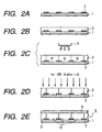
- FIG. 2A to FIG. 2E are illustrative views of a liquid crystal color filter according to one embodiment of the present invention.
- FIG. 2A shows a light-transmissible substrate 1 (for example, a glass substrate or the like) on which a light shield section 2 (hereinafter, referred to as "a black matrix”) is formed in a pattern shape.
- a method for forming the black matrix 2 includes that comprising the stps of forming a thin film of a metal (for example, chrome, chromic oxide or the like) by spattering or evaporation and thereafter conducting patterning with a photolithography process, when the matrix is directly provided on the substrate.
- a patterning method with a general photolithography process is exemplified.
- a layer containing a resin composition that can be cured is formed on the substrate 1 on which the black matrix 2 has been formed, and then an ink receiving layer 3 is formed on the substrate 1 (FIG. 2B).
- a substrate a glass is generally employed.
- a crystal acrylic resin substrate or the like can be employed without being limited to the glass.
- a publicly known material can be used for forming the ink receiving layer 3.
- an acrylic resin, an epoxy resin, or an imide-based resin is preferred.
- cellulose-based water-soluble polymers such as hydroxypropyl cellulose, hydroxyethyl cellulose, methyl cellulose, carboxymethyl cellulose are preferred.
- polyvinyl pyrrolidone polyvinyl alcohol, polyvinyl acetal, polyurethane, carboxymethyl cellulose, polyester or the like, or natural resins such as albumin, gelatin, casein, starch, cationic starch, gum arabic, alginic acid soda or the like
- natural resins such as albumin, gelatin, casein, starch, cationic starch, gum arabic, alginic acid soda or the like
- a mixture of hydroxypropyl cellulose and methylolmelanin or a compound including at least a single monomer consisting of the following structural unit (10) and/or a copolymer with another vinyl based monomer is preferably employed.
- R 12 denotes H or CH 3 and the like
- R 13 denotes H or an unsubstituted alkyl group or an alkyl group that may be substituted by a linear or branched alkyl group or the like with 1 to 5 carbons.
- the monomer equivalent to a structural unit represented by the above formula (10) includes, for example, N-methylolacrylamide, N-methoxymethylacrylamide, N-ethoxymethylacrylamide, N-isopropoxymethylacrylamide, N-methylolmethacrylamide, N-methoxymethylmethacrylamide, N-ethoxymethylmethacrylamide or the like.
- the other vinyl based monomer includes acrylic acid, methacrylic acid, acrylic ester (methyl acrylate, ethyl acrylate or the like), methacrylic ester (methyl methacrylate, ethyl methacrylate or the like), a vinyl monomer containing a hydroxyl group (hydroxymethyl methacrylate, hydroxyethyl methacrylate, hydroxymethyl acrylate, hydroxyethyl methacrylate, hydroxymethyl acrylate, hydroxyethyl acrylate or the like), styrene, ⁇ -methyl styrene, acrylamide, methacrylamide, acrylonitryl, allylamine, vinylamine, vinyl acetate, vinyl propionate or the like.
- a rate of copolymerization between a monomer equivalent to the structural unit of the above general formula (10) and another vinyl monomer is preferably in the range of 95:5 to 5:95 at a molar ratio.
- additives may be contained in the above receiving layer 3 as required.
- a specific example of the additives includes a variety of surface active agents, dye fixing agents (water proofing agents), bubble extinguishing agents, anti-oxidization agents, fluorescent whitening agents, ultraviolet-ray absorbers, viscosity adjusters, pH adjusters, mildew proofing agents, plasticizers or the like. These additives may be arbitrarily selected according to their purposes from the conventional publicly known compounds.
- a method for forming the ink receiving layer 3 includes spin coating, roll coating, bar coating, spray coating, dip coating or the like. In addition, a pre-baking may be carried out as required.
- FIG. 3 is a block diagram depicting a construction of the apparatus for drawing a coloring site of the color filter with the ink jet process.
- CPU 21 is connected to an ink jet recording head 4 via a head driving circuit 22. Further, CPU 21 is constructed so that the control program information in a program memory 23 is inputted. Furthermore, CPU 21 moves the ink jet recording head 23 to a predetermined position of a substrate 1 (not shown), brings a desired position on the substrate 1 downward of the ink jet head, and ejects an ink 24 of a desired color to that position, thereby perform coloring. This process is carried out for a desired pixel position on the substrate 1, thereby a color filter can be manufactured.
- the ink receiving layer 3 is cured (FIG. 2D).
- the curing method suitable to a curable resin used for the ink receiving layer may be used. For example, heating, light irradiation, or heating and light irradiation is conducted to cure the layer, thereby to form the colored pixel 11 of each color.
- the light to be irradiated to the ink absorption layer is not particularly limited; and however, in particular, the Deep-UV light is preferable, and the light irradiation condition of 1 to 3000 mJ/cm 2 is preferred.
- heat treatment using a means such as oven and hot plate or the like is exemplified. The heat treatment may be carried out for 10 seconds to 20 minutes under temperature conditions of 50°C to 180°C.
- a protective layer 6 is formed on the cured ink receiving layer 3 as required (FIG. 2E).
- the protective layer 6 can be provided by coating a resin material curable by light irradiation or heat treatment, for example, and then curing the material; or forming an inorganic film through evaporation or spattering.
- a preferable material usable for the protective layer is free of losing transparency required for a color filter when the protective layer is formed, and is endurable against ITP-form process, oriented film forming process or the like to be carried out as required after the layer has been formed.
- the organic material includes an acrylic resin such as epoxy acrylate, an urethane acrylate or the like; and the inorganic material includes SiO 2 or the like. In this manner, the color filter 9 according to this embodiment can be obtained.
- the substrate 1 having the black matrix formed on its surface is provided to form the ink receiving layer 3 so as to cover the black matrix 2 (FIG. 4A and FIG. 4B).
- a material which lowers the ink absorptibity of the ink receiving layer 3 through light irradiation is preferably employed for the ink receiving layer 3.
- a light polymerization initiator further contained in the constituent material of the ink receiving layer 3 employed in the aforementioned first embodiment is preferably employed.
- An example of the light polymerization initiator preferably used therein includes, for example, an onium salt or halide triazine compound.
- the onium salt include triphenylsulfoniumhexafluoroantimonate, triphenylsulfoniumtetrafluorobolate, triphenylsulfoniumhexafluorophosphate, triphenylsulfoniumtrifluoromethylsulfonate or these derivatives, and further, diphenyliodoniumhexafluoroantimonate, diphenyliodoniumtetrafluorobolate, diphenyliodoniumhexafluorophosphate, diphenyliodoniumtrifluoromethylfurfonate or these derivatives.
- halide triazine compounds are preferably employed.
- the amount of the above mentioned polymerization initiator to be added is 0.01 to 20% by weight or is preferably 0.1 to 10% by weight to the above mentioned ink receiving material.
- a compound such as perylene, anthracene or the like may be added as a sensitizer.
- a site corresponding to the black matrix of the ink receiving layer 3 is selectively exposed by using a photo mask 41 or the like, for example, and the site corresponding to the black matrix 2 of the ink receiving layer 3 is cured (FIG. 4C).
- a site (non-coloring site) 42 with low ink absorptibity is selectively formed on the ink receiving layer 3.
- a photo mask employed for pattern exposure for example, the mask comprising an opening 43 that can be selectively exposed to an ink receiving layer site corresponding to the black matrix 2.
- a width (Y) of the opening 43 is preferably narrower than a width (X) of the black matrix 2.
- a width of the non-coloring site of the ink receiving layer 3 is preferably narrower than the width (X) of the black matrix 2.
- Such non-coloring site can be formed by employing the photo mask 42 in which the width (Y) of the above mentioned opening 43 is narrower than the width (X) of the black matrix 2.
- the light irradiated to the ink absorption layer when the non-coloring site 43 is formed is not particularly limited.
- the Deep-UL light and the light irradiation condition of 1 to 3000 mJ/cm 2 are preferably used.
- Heat treatment is carried out by means of oven, hot plate or the like, for example. Such heat treatment may be carried out under a temperature condition of 50°C to 180°C for 10 seconds to 20 minutes.
- a resin on the black matrix is cured so that an ink is not applied between pixels.
- a water repellence agent or the like which lowers ink adhesion may be applied onto the black matrix so that the ink is not applied on the surface of the black matrix, thereby to provide non-coloring properties.
- a substrate having a black matrix 2 formed on its surface is provided in a manner similar to that described in the first embodiment (FIG. 5A).
- a predetermined thickness for example, a wall of 0.5 micrometer or more is preferably formed between pixels.
- a black resin resist is preferably patterned, thereby to form the black matrix 2.
- an R ink 51, a G ink 52, and a B ink 53 are applied so as to compensate for a light transmission section 55 between black matrixes 2 using the ink jet system.
- these inks are preferably applied so that each color ink does not overlay on the black matrix 2.
- an R ink giving a red pixel for example, there can be employed an ink including at least one pigment selected from metal-containing azopyrazolone dyes indicated by the above formulas (R1-1) and (R1-2) and dyes each having a xanthene backbone indicated by the formulas (R2-1) and (R2-2).
- a G ink giving a green pixel for example, there can be employed an ink including at least one coloring matter selected from dyes each having a structure indicated by the formulas (G1), (G2), (G3), and (G4).
- a B ink giving a blue pixel there can be employed an ink including at least one coloring matter selected from dyes each having a structure indicated by the formula (B1) or an ink including at least one coloring matter selected from dyes each having a structure indicated by the formula (B1) and at least one coloring matter selected from dyes each having a structure indicated by the formula (B2).
- at least one ink selected from the R, G, and B inks, or preferably all the inks in which a resin curable by applying light and/or heat energy is contained can be preferably employed.
- the G and B inks containing the resin therein are preferably employed.
- a variety of commercially available resins and curing agents can be employed, which preferably cause a problem such as fixation in the ink or the like.
- Such material includes an acrylic resin, an epoxy resin, a melanine resin or the like.
- a volume of a light curable component contained in the ink, a thermally curable component, or a component curable by light and heat is preferably about 0.1 to 20 %, for example, based on the total weight of the ink.
- a curable resin composition is applied so as to cover a colored site 54 formed by the black matrix 2 and each color ink, the colored site 54 is completely cured by light irradiation and/or heat treatment, thereby to complete a colored pixel 11, and a curable resin composition is cured to form a protective layer 6 and obtained a color filter.
- the protective film 6 may be formed by curing a curable resin material through light irradiation and/or heat treatment or an inorganic film is formed by evaporation or spattering to be a protective layer 6.
- a method for manufacturing a color filter using the ink jet process has been described.
- a method for manufacturing a color filter according to the present invention is not particularly limited, and for example, a dyeing process, a pigment dispersing process, an electrolytic deposition process and the like are exemplified.
- a water-soluble polymeric material which is a dyeing material is applied onto a glass substrate, this material is patterned in a desired shape by a photolithography process, and the thus obtained pattern is immersed in a dyeing bath and is colored therein. This process is repeated three times, thereby to form R (red), G (green), and B (blue) colored layers.
- the pigment dispersing process is substituted by the dyeing process.
- a photosensitive resin layer having a pigment dispersed on a substrate is formed, and a monochrome pattern is obtained by pattering this layer. Further, this process is repeated three times, thereby to form the R, G, and B colored layers.
- a transparent electrode is patterned on a substrate, and the electrode is immersed into an electrolytic deposition coating liquid containing a pigment, a resin, a dielectric or the like to electrically deposit a first color. This process is repeated three times, thereby to form the R, G, and B colored layers, and finally it is baked.
- a pigment is dispersed in a thermally curable resin, and printing is repeated three times thereby to coat R, G, and B. Thereafter, a resin is thermally cured, thereby to form the colored layers.
- a protective film is generally formed on a color filter layer.
- FIG. 1 A sectional view of a TFT color liquid crystal display panel incorporating a color filter according to the present invention is as shown in FIG. 1.
- Another construction of the liquid crystal display panel includes a black matrix (BM) on-array type (type of which BM is formed on the opposite TFT substrate side as shown in FIG. 6), a color filter (CF) on-array type (type of which a CF section is formed on the TFT substrate side as shown in FIG. 7) or the like.
- BM black matrix
- CF color filter
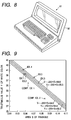
- the thus prepared liquid crystal display panel is employed as an image display device 92 such as a computer 91, as shown in FIG. 8, for example.
- a color filter with high color density and superior transparency As a result, a proper tone representation in an area close to black is obtained without increasing back light luminance, for example.
- a computer comprising a high quality image display section can be obtained by employing a liquid crystal display panel for high quality image display, and by employing that liquid crystal display panel for the image display section.
- a photosensitive resin composition comprising of an acrylic copolymer composed of the following compositions was applied by spinner on a surface of a polished no-alkali glass, the composition was baked at 90°C for 20 minutes, thereby to form a photosensitive resin layer of 1 ⁇ m in film thickness.
- a pattern exposure was done via a photo mask so that an area other than that in which a color filter is to be formed is exposed, and a photosensitive resin layer was partially cured.
- each of the R, G, and B inks adjusted in the composition shown in table 6 below was ejected by the ink jet system (a driving voltage: 27 volts (V) and a pulse width (7 ⁇ sec), the ink to be ejected eight times per pixel was applied to the photosensitive resin layer, the resin layer was baked at 90°C for 20 minutes and at 200°C for 60 minutes, and each colored section was formed.
- the thus obtained color filter showed 0.05844 in an area (S) for a triangle formed by connecting the xy chromaticity coordinate (standard C light source) of each of the R, G, and B pixels, and the stimulus value (Y) of the white color synthesized at this time was 39.3. That is, the condition of Y ⁇ -255 * S + 54 was met.
- this color filter was used to fabricate a liquid crystal display device, and a color pattern was displayed using a back light source of 2500 cd/m 2 in luminance at a color temperature of about 7000 K under an observational environment of 500 lux in illuminance. As a result, the color pattern was identified even at a gradation boundary, and a good quality image was obtained.
- a color filter was fabricated in a manner similar to that in Example 1 except the use of the R, G, and B inks each shown in table 7 below.
- the thus obtained color filter showed 0.06016 in an area (S) for a triangle formed by connecting the xy chromaticity coordinate (standard C light source) of each of the R, G, and B pixels, and the stimulus value (Y) of the white color synthesized at this time was 39.5. That is, the condition of Y ⁇ -255 * S + 54.5 was met.
- a liquid crystal display device was fabricated using this color filter, and a color pattern was displayed using a back light source with 2500 cd/m 2 in luminance at a color temperature of about 7000 K under an observational condition of 500 lux in illuminance. As a result, the color pattern was identified even at a gradation boundary, and a superior quality image was obtained.
- a color filter was fabricated in a manner similar to that in Example 1 except the use of the R, G, and B inks each shown in table 8 below.
- C.I. Direct Blue 199 3.4 Ethylene glycol 30 Ethylene glycol 30 Ethylene glycol 30 Water 65.6 Water 62 Water 64
- the thus obtained color filter showed 0.07667 in an area (S) of a triangle formed by connecting the xy chromaticity coordinate (standard C light source) of each of the R, G, and B pixels, and a stimulus value (Y) of a white color was 35.9. That is, the condition of Y ⁇ -255 * S + 55 was met.
- a liquid crystal display device was fabricated using this color filter, and a color pattern was displayed using a back light of 2500 cd/m 2 in luminance at a color temperature of about 7000 K under an observational environment of 500 lux in illuminance. As a result, the color pattern was identified even at a gradation boundary, and a very good quality image was obtained.
- a color filter was fabricated in a manner similar to that in Example 1 except the use of the R, G, and B inks each shown in table 9 below.
- the thus obtained color filter showed 0.05766 in an area (S) for a triangle formed by connecting the xy chromaticity coordinate (standard C light source) of each of the R, G, and B pixels, and a stimulus value (Y) of a white color synthesized at this time was 41. That is, the condition of Y ⁇ -255 * S + 55.5 was met.
- a liquid crystal display device was fabricated using this color filter, a color pattern was displayed using a back light source of 2500 cd/m 2 in luminance at a color temperature of about 7000 K under an observational environment of 500 lux in illuminance to.
- the color pattern was identified even at a gradation boundary, and a very superior image was obtained.
- a color filter was fabricated in a manner similar to that in Example 1 except the use of the R, G, and B inks each shown in table 10 below.
- the thus obtained color filter showed 0.07134 in an area (S) for a triangle formed by connecting the xy chromaticity coordinate (standard C light source) of each of the R, G, and B pixels, and a stimulus value (Y) of a white color synthesized at this time was 38.2. That is, the condition of Y ⁇ -255 * S + 56 was met.
- a liquid crystal display device was fabricated using this color filter, and a color pattern was displayed using a back light source of 2500 cd/m 2 in luminance at a color temperature of about 7000 K under an observational environment of 500 lux in illuminance. As a result, the color pattern was identified even at a gradation boundary, and a very superior image was obtained.
- a color filter was fabricated in a manner similar to that in the foregoing Example 1 except the use of the R, G, and B inks each shown in table 11 below.
- R ink G ink B ink C.I. Acid Red 35 4 parts by weight C.I. Acid Green 73 3 parts by weight C.I. Acid Blue 80 4.5 parts by weight
- the thus obtained color filter showed 0.0635 in an area (S) for a triangle formed by connecting the xy chromaticity coordinate (standard C light source) of each of the R, G, and B pixels, and a stimulus value (Y) of a white color synthesized at this time was 36. That is, the condition of Y ⁇ -255 * S + 54 was not met.
- a liquid crystal display device was fabricated using this color filter, and a color pattern was displayed using a back light source of 2500 cd/m 2 at a color temperature of about 7000 K under an observational environment of 500 lux in illuminance.
- the tone representation is hardly seen in an area close to black compared with the color pattern of Example 1, and the gradation boundary was blocked up.
- the density of each ink employed for manufacture of the color filter of Comparative Example 1 was increased by 1.3, and a color filter was fabricated using an ink in which water was reduced by the thus increased density.
- the thus obtained color filter showed 0.0840 in an area (S) for a triangle formed by connecting the xy chromaticity coordinate (standard C light source) of each of the R, G, and B pixels, and a stimulus value (Y) of a white color synthesized at this time was 30. That is, the condition of Y ⁇ -255 * S + 54 was not met.
- a liquid crystal display device was fabricated using this color filter, and a color pattern was displayed using a back light source of 2500 cd/m 2 at a color temperature of about 7000 K under an observational environment of 500 lux in illuminance.
- the tone representation was hardly seen at an area close to black compared with the color pattern of Example 1, and pthe gradation boundary was blocked up.
Landscapes
- Physics & Mathematics (AREA)
- Chemical & Material Sciences (AREA)
- General Physics & Mathematics (AREA)
- Optics & Photonics (AREA)
- Organic Chemistry (AREA)
- Life Sciences & Earth Sciences (AREA)
- Engineering & Computer Science (AREA)
- Materials Engineering (AREA)
- Wood Science & Technology (AREA)
- Chemical Kinetics & Catalysis (AREA)
- Optical Filters (AREA)
- Liquid Crystal (AREA)
Applications Claiming Priority (2)
| Application Number | Priority Date | Filing Date | Title |
|---|---|---|---|
| JP17140498A JP2000009916A (ja) | 1998-06-18 | 1998-06-18 | カラーフィルタ、液晶パネル、コンピュータ及びカラーフィルタの製造方法 |
| JP17140498 | 1998-06-18 |
Publications (2)
| Publication Number | Publication Date |
|---|---|
| EP0965874A2 true EP0965874A2 (de) | 1999-12-22 |
| EP0965874A3 EP0965874A3 (de) | 2005-07-20 |
Family
ID=15922533
Family Applications (1)
| Application Number | Title | Priority Date | Filing Date |
|---|---|---|---|
| EP99111660A Withdrawn EP0965874A3 (de) | 1998-06-18 | 1999-06-16 | Farbfilter, Flüssigkristallanzeigetafel, Computer und Verfahren zur Herstellung eines Farbfilters |
Country Status (3)
| Country | Link |
|---|---|
| US (1) | US6238827B1 (de) |
| EP (1) | EP0965874A3 (de) |
| JP (1) | JP2000009916A (de) |
Cited By (3)
| Publication number | Priority date | Publication date | Assignee | Title |
|---|---|---|---|---|
| WO2002034844A1 (en) * | 2000-10-27 | 2002-05-02 | Avecia Limited | Composition containing an azaphthalocyanine and use |
| WO2004018477A2 (en) * | 2002-08-14 | 2004-03-04 | Ciba Specialty Chemicals Holdings Inc. | Liquid crystal display and colour filter with improved transparency for green light |
| WO2005010111A1 (en) * | 2003-07-18 | 2005-02-03 | Hewlett-Packard Development Company, L.P. | Magenta ink-jet inks |
Families Citing this family (21)
| Publication number | Priority date | Publication date | Assignee | Title |
|---|---|---|---|---|
| US6243068B1 (en) * | 1998-05-29 | 2001-06-05 | Silicon Graphics, Inc. | Liquid crystal flat panel display with enhanced backlight brightness and specially selected light sources |
| US6654082B1 (en) * | 1998-09-16 | 2003-11-25 | Optrex Corporation | Liquid crystal display element and color display device having particular transflector |
| JP2002098948A (ja) * | 2000-09-20 | 2002-04-05 | Hitachi Ltd | 液晶表示装置の製造方法 |
| JP4516744B2 (ja) * | 2003-12-18 | 2010-08-04 | 富士フイルム株式会社 | フタロシアニン化合物、インク、インクジェット記録方法、および画像形成方法 |
| JP4659403B2 (ja) * | 2004-07-15 | 2011-03-30 | 富士フイルム株式会社 | フタロシアニン化合物、インク、インクジェット記録方法、および画像形成方法 |
| US7742155B2 (en) | 2005-03-31 | 2010-06-22 | Fujifilm Corporation | Diffusion material, diffusion material evaluating method, blending method for fine particles in the diffusion material, and production method for the diffusion material |
| US7884900B2 (en) * | 2005-05-26 | 2011-02-08 | Toshiba Matsushita Display Technology Co., Ltd. | Liquid crystal display device with partition walls made of color filter layers as a dam for the light shielding material |
| CN101384670B (zh) * | 2006-02-10 | 2013-06-05 | 日本化药株式会社 | 四氮杂卟啉色素、油墨、油墨组及着色体 |
| KR101321889B1 (ko) * | 2006-04-07 | 2013-10-25 | 니폰 가야꾸 가부시끼가이샤 | 포르피라진 색소, 잉크, 잉크세트 및 착색체 |
| CN101631834B (zh) | 2007-03-14 | 2014-10-22 | 日本化药株式会社 | 四氮杂卟啉色素、油墨、油墨组及着色体 |
| US20080237657A1 (en) * | 2007-03-26 | 2008-10-02 | Dsm Solution, Inc. | Signaling circuit and method for integrated circuit devices and systems |
| JP4640406B2 (ja) * | 2007-11-27 | 2011-03-02 | セイコーエプソン株式会社 | カラーフィルター用インク、カラーフィルター用インクセット、カラーフィルター、画像表示装置、および、電子機器 |
| US7981204B2 (en) * | 2007-12-28 | 2011-07-19 | Nippon Kayaku Kabushiki Kaisha | Porphyrazine coloring matter and ink composition containing the same |
| TW201005045A (en) * | 2008-06-30 | 2010-02-01 | Nippon Kayaku Kk | Porphyrazine pigment, ink composition and colored article |
| WO2010073603A1 (ja) | 2008-12-25 | 2010-07-01 | 日本化薬株式会社 | ポルフィラジン色素、これを含有するインク組成物及び着色体 |
| JP5799485B2 (ja) * | 2008-12-25 | 2015-10-28 | 住友化学株式会社 | 着色感光性樹脂組成物 |
| JP5796273B2 (ja) * | 2008-12-25 | 2015-10-21 | 住友化学株式会社 | 着色感光性樹脂組成物 |
| JP2010210853A (ja) * | 2009-03-10 | 2010-09-24 | Seiko Epson Corp | 液滴吐出装置、液滴吐出方法、及びカラーフィルターの製造方法 |
| JP2010217643A (ja) * | 2009-03-18 | 2010-09-30 | Seiko Epson Corp | 液滴吐出装置、液滴吐出方法、及びカラーフィルターの製造方法 |
| CA2758708C (en) | 2009-04-15 | 2016-09-13 | Nippon Kayaku Kabushiki Kaisha | Porphyrazine coloring matter, ink composition containing the same and colored product |
| JP5381286B2 (ja) * | 2009-04-27 | 2014-01-08 | 東洋インキScホールディングス株式会社 | カラーフィルタ用青色着色組成物およびカラーフィルタ |
Citations (5)
| Publication number | Priority date | Publication date | Assignee | Title |
|---|---|---|---|---|
| EP0703471A2 (de) * | 1994-09-21 | 1996-03-27 | Canon Kabushiki Kaisha | Farbfilter, Herstellungsverfahren desselben, und damit ausgestattete Flüssigkristallanzeigetafel |
| JPH08327811A (ja) * | 1995-06-01 | 1996-12-13 | Canon Inc | カラーフィルタ用インク、カラーフィルタ、カラーフィルタの製造方法および液晶パネル |
| EP0763539A2 (de) * | 1995-09-14 | 1997-03-19 | Orient Chemical Industries, Ltd. | Neue Phthalocyanin- oder Naphthalocyaninderivate |
| US5693436A (en) * | 1994-12-08 | 1997-12-02 | Fuji Photo Film Co., Ltd. | Method for forming a color filter |
| JPH10197710A (ja) * | 1996-12-27 | 1998-07-31 | Canon Inc | カラーフィルタ及びこれを用いた液晶素子 |
Family Cites Families (7)
| Publication number | Priority date | Publication date | Assignee | Title |
|---|---|---|---|---|
| JP3332515B2 (ja) | 1993-11-24 | 2002-10-07 | キヤノン株式会社 | カラーフィルタ、その製造方法及び液晶パネル |
| TW417034B (en) | 1993-11-24 | 2001-01-01 | Canon Kk | Color filter, method for manufacturing it, and liquid crystal panel |
| EP0665449B1 (de) | 1994-01-28 | 2001-10-24 | Canon Kabushiki Kaisha | Farbfilter, Verfahren zu seiner Herstellung, und Flüssigkristalltafel |
| JP3014923B2 (ja) | 1994-06-24 | 2000-02-28 | キヤノン株式会社 | カラーフィルターおよびその製造方法ならびにそのフィルターを用いた液晶表示装置 |
| JPH08227011A (ja) | 1994-09-30 | 1996-09-03 | Canon Inc | カラーフィルタ、その製造方法、液晶パネル、及びこれを備えた情報処理装置 |
| US5736278A (en) | 1995-06-20 | 1998-04-07 | Canon Kabushiki Kaisha | Color filter having light screening resin layer and filter resin layer |
| US5948577A (en) | 1997-06-02 | 1999-09-07 | Canon Kabushiki Kaisha | Color filter substrate, liquid crystal display device using the same and method of manufacturing color filter substrate |
-
1998
- 1998-06-18 JP JP17140498A patent/JP2000009916A/ja not_active Withdrawn
-
1999
- 1999-06-15 US US09/333,041 patent/US6238827B1/en not_active Expired - Lifetime
- 1999-06-16 EP EP99111660A patent/EP0965874A3/de not_active Withdrawn
Patent Citations (5)
| Publication number | Priority date | Publication date | Assignee | Title |
|---|---|---|---|---|
| EP0703471A2 (de) * | 1994-09-21 | 1996-03-27 | Canon Kabushiki Kaisha | Farbfilter, Herstellungsverfahren desselben, und damit ausgestattete Flüssigkristallanzeigetafel |
| US5693436A (en) * | 1994-12-08 | 1997-12-02 | Fuji Photo Film Co., Ltd. | Method for forming a color filter |
| JPH08327811A (ja) * | 1995-06-01 | 1996-12-13 | Canon Inc | カラーフィルタ用インク、カラーフィルタ、カラーフィルタの製造方法および液晶パネル |
| EP0763539A2 (de) * | 1995-09-14 | 1997-03-19 | Orient Chemical Industries, Ltd. | Neue Phthalocyanin- oder Naphthalocyaninderivate |
| JPH10197710A (ja) * | 1996-12-27 | 1998-07-31 | Canon Inc | カラーフィルタ及びこれを用いた液晶素子 |
Non-Patent Citations (2)
| Title |
|---|
| PATENT ABSTRACTS OF JAPAN vol. 1997, no. 04, 30 April 1997 (1997-04-30) -& JP 08 327811 A (CANON INC), 13 December 1996 (1996-12-13) * |
| PATENT ABSTRACTS OF JAPAN vol. 1998, no. 12, 31 October 1998 (1998-10-31) -& JP 10 197710 A (CANON INC), 31 July 1998 (1998-07-31) * |
Cited By (4)
| Publication number | Priority date | Publication date | Assignee | Title |
|---|---|---|---|---|
| WO2002034844A1 (en) * | 2000-10-27 | 2002-05-02 | Avecia Limited | Composition containing an azaphthalocyanine and use |
| WO2004018477A2 (en) * | 2002-08-14 | 2004-03-04 | Ciba Specialty Chemicals Holdings Inc. | Liquid crystal display and colour filter with improved transparency for green light |
| WO2004018477A3 (en) * | 2002-08-14 | 2004-04-15 | Ciba Sc Holding Ag | Liquid crystal display and colour filter with improved transparency for green light |
| WO2005010111A1 (en) * | 2003-07-18 | 2005-02-03 | Hewlett-Packard Development Company, L.P. | Magenta ink-jet inks |
Also Published As
| Publication number | Publication date |
|---|---|
| US6238827B1 (en) | 2001-05-29 |
| EP0965874A3 (de) | 2005-07-20 |
| JP2000009916A (ja) | 2000-01-14 |
Similar Documents
| Publication | Publication Date | Title |
|---|---|---|
| US6238827B1 (en) | Color filter, liquid crystal display panel, computer, and method for manufacturing color filter | |
| EP0655631B1 (de) | Verfahren zu Herstellung eines Farbfilters und eines Flüssigkristallschirms | |
| EP0703471B1 (de) | Farbfilter, Herstellungsverfahren desselben, und damit ausgestattete Flüssigkristallanzeigetafel | |
| TWI396871B (zh) | 具改良之著色劑分布的彩色濾光片元件 | |
| US6533852B2 (en) | Recording ink, method for ink jet recording, method for producing color filter, color filter, method for producing liquid crystal display panel, liquid crystal display panel, and yellow ink | |
| KR101988047B1 (ko) | Lcd용 고투과 녹색 염료 및 그 제조 방법 | |
| EP0947859B1 (de) | Tinte, Farbfilter, Flüssigkristallanzeige und Computer, sowie Verfahren zur Herstellung des Farbfilters | |
| JPH112716A (ja) | カラーフィルタ、これを用いた液晶素子及びこれらの製造方法、並びに該製造方法に用いられるインクジェット用インク | |
| JP5949246B2 (ja) | カラーフィルタ用着色組成物およびカラーフィルタ | |
| JP2014085565A (ja) | カラーフィルタ用着色組成物およびカラーフィルタ | |
| JPH0829771A (ja) | カラーフィルタ、その製造方法、及びカラーフィルタを備えた液晶パネル | |
| JP2017198815A (ja) | カラーフィルタ用着色組成物及びカラーフィルタ | |
| JPH11302285A (ja) | ポルフィラジン誘導体、インク、カラーフィルタ、液晶パネル、コンピュータ及びカラーフィルタの製造方法 | |
| JPH11302283A (ja) | フタロシアニン化合物、インク、カラーフィルタ、液晶パネル、コンピュータ及びカラーフィルタの製造方法 | |
| US6063174A (en) | Ink for use in ink-jet recording, color filter, liquid crystal panel, computer and method for producing color filter | |
| JP5910217B2 (ja) | カラーフィルタ用赤色着色組成物及びカラーフィルタ | |
| JP3893391B2 (ja) | Ndフィルタの製造方法 | |
| JP2001288393A (ja) | 記録用インク、インクジェット記録方法、カラーフィルタの製造方法、カラーフィルタ、液晶ディスプレイパネルの製造方法、液晶ディスプレイパネル、及び黄色インク | |
| JP2002212471A (ja) | インク、カラーフィルターとその製造方法、液晶パネル、コンピュータ及び画像表示デバイス | |
| KR20140034963A (ko) | Lcd용 고투과 황색 염료 및 그 제조 방법 | |
| JP2002302626A (ja) | 記録用インク、インクジェット記録方法、カラーフィルタの製造方法、液晶ディスプレイパネルの製造方法及び液晶ディスプレイパネル | |
| JPH0829777A (ja) | カラーフィルタ、その製造方法、及びカラーフィルタを備えた液晶パネル | |
| JP2003321634A (ja) | インク、カラーフィルターとその製造方法、液晶パネル、コンピュータ及び画像表示デバイス | |
| JP3984725B2 (ja) | インクジェット記録用インク、カラーフィルタ、液晶パネル、コンピュータ及びカラーフィルタの製造方法 | |
| JP2001214096A (ja) | 記録用インク、インクジェット記録方法、カラーフィルタの製造方法、被膜性インク、液晶ディスプレイパネルの製造方法、及び、液晶ディスプレイパネル |
Legal Events
| Date | Code | Title | Description |
|---|---|---|---|
| PUAI | Public reference made under article 153(3) epc to a published international application that has entered the european phase |
Free format text: ORIGINAL CODE: 0009012 |
|
| AK | Designated contracting states |
Kind code of ref document: A2 Designated state(s): AT BE CH CY DE DK ES FI FR GB GR IE IT LI LU MC NL PT SE |
|
| AX | Request for extension of the european patent |
Free format text: AL;LT;LV;MK;RO;SI |
|
| PUAL | Search report despatched |
Free format text: ORIGINAL CODE: 0009013 |
|
| AK | Designated contracting states |
Kind code of ref document: A3 Designated state(s): AT BE CH CY DE DK ES FI FR GB GR IE IT LI LU MC NL PT SE |
|
| AX | Request for extension of the european patent |
Extension state: AL LT LV MK RO SI |
|
| 17P | Request for examination filed |
Effective date: 20060120 |
|
| AKX | Designation fees paid |
Designated state(s): DE FR GB IT |
|
| 17Q | First examination report despatched |
Effective date: 20060824 |
|
| STAA | Information on the status of an ep patent application or granted ep patent |
Free format text: STATUS: THE APPLICATION HAS BEEN WITHDRAWN |
|
| 18W | Application withdrawn |
Effective date: 20070301 |