EP0964995B1 - Systemes de demarrage pour moteur a combustion interne et procede de demarrage correspondant - Google Patents
Systemes de demarrage pour moteur a combustion interne et procede de demarrage correspondant Download PDFInfo
- Publication number
- EP0964995B1 EP0964995B1 EP98913670A EP98913670A EP0964995B1 EP 0964995 B1 EP0964995 B1 EP 0964995B1 EP 98913670 A EP98913670 A EP 98913670A EP 98913670 A EP98913670 A EP 98913670A EP 0964995 B1 EP0964995 B1 EP 0964995B1
- Authority
- EP
- European Patent Office
- Prior art keywords
- energy
- internal combustion
- starter
- combustion engine
- starting
- Prior art date
- Legal status (The legal status is an assumption and is not a legal conclusion. Google has not performed a legal analysis and makes no representation as to the accuracy of the status listed.)
- Expired - Lifetime
Links
- 239000007858 starting material Substances 0.000 title claims abstract description 44
- 238000002485 combustion reaction Methods 0.000 title claims abstract description 35
- 238000000034 method Methods 0.000 title claims abstract description 17
- 239000003990 capacitor Substances 0.000 claims abstract description 30
- 230000003197 catalytic effect Effects 0.000 claims description 5
- 230000007774 longterm Effects 0.000 claims description 5
- 230000001419 dependent effect Effects 0.000 claims description 3
- 230000008569 process Effects 0.000 abstract description 8
- 230000006870 function Effects 0.000 description 10
- 239000003054 catalyst Substances 0.000 description 7
- PXHVJJICTQNCMI-UHFFFAOYSA-N Nickel Chemical compound [Ni] PXHVJJICTQNCMI-UHFFFAOYSA-N 0.000 description 4
- 238000004146 energy storage Methods 0.000 description 4
- 238000010438 heat treatment Methods 0.000 description 4
- XEEYBQQBJWHFJM-UHFFFAOYSA-N Iron Chemical compound [Fe] XEEYBQQBJWHFJM-UHFFFAOYSA-N 0.000 description 2
- 239000002826 coolant Substances 0.000 description 2
- 230000007423 decrease Effects 0.000 description 2
- 230000003247 decreasing effect Effects 0.000 description 2
- 229910052759 nickel Inorganic materials 0.000 description 2
- 230000001360 synchronised effect Effects 0.000 description 2
- 238000004804 winding Methods 0.000 description 2
- 239000002253 acid Substances 0.000 description 1
- 230000009286 beneficial effect Effects 0.000 description 1
- 230000002457 bidirectional effect Effects 0.000 description 1
- 230000033228 biological regulation Effects 0.000 description 1
- 229910052793 cadmium Inorganic materials 0.000 description 1
- BDOSMKKIYDKNTQ-UHFFFAOYSA-N cadmium atom Chemical compound [Cd] BDOSMKKIYDKNTQ-UHFFFAOYSA-N 0.000 description 1
- 230000008859 change Effects 0.000 description 1
- 238000006243 chemical reaction Methods 0.000 description 1
- 238000010276 construction Methods 0.000 description 1
- 238000001514 detection method Methods 0.000 description 1
- 238000010586 diagram Methods 0.000 description 1
- 230000005284 excitation Effects 0.000 description 1
- 239000000835 fiber Substances 0.000 description 1
- 230000005669 field effect Effects 0.000 description 1
- 239000007789 gas Substances 0.000 description 1
- 238000009499 grossing Methods 0.000 description 1
- 230000006698 induction Effects 0.000 description 1
- 229910052742 iron Inorganic materials 0.000 description 1
- 239000000463 material Substances 0.000 description 1
- 238000005259 measurement Methods 0.000 description 1
- 238000002360 preparation method Methods 0.000 description 1
- 238000003825 pressing Methods 0.000 description 1
- 230000009467 reduction Effects 0.000 description 1
- 239000000126 substance Substances 0.000 description 1
Images


Classifications
-
- F—MECHANICAL ENGINEERING; LIGHTING; HEATING; WEAPONS; BLASTING
- F02—COMBUSTION ENGINES; HOT-GAS OR COMBUSTION-PRODUCT ENGINE PLANTS
- F02N—STARTING OF COMBUSTION ENGINES; STARTING AIDS FOR SUCH ENGINES, NOT OTHERWISE PROVIDED FOR
- F02N19/00—Starting aids for combustion engines, not otherwise provided for
- F02N19/02—Aiding engine start by thermal means, e.g. using lighted wicks
- F02N19/04—Aiding engine start by thermal means, e.g. using lighted wicks by heating of fluids used in engines
-
- F—MECHANICAL ENGINEERING; LIGHTING; HEATING; WEAPONS; BLASTING
- F02—COMBUSTION ENGINES; HOT-GAS OR COMBUSTION-PRODUCT ENGINE PLANTS
- F02N—STARTING OF COMBUSTION ENGINES; STARTING AIDS FOR SUCH ENGINES, NOT OTHERWISE PROVIDED FOR
- F02N11/00—Starting of engines by means of electric motors
- F02N11/08—Circuits or control means specially adapted for starting of engines
- F02N11/0862—Circuits or control means specially adapted for starting of engines characterised by the electrical power supply means, e.g. battery
- F02N11/0866—Circuits or control means specially adapted for starting of engines characterised by the electrical power supply means, e.g. battery comprising several power sources, e.g. battery and capacitor or two batteries
-
- F—MECHANICAL ENGINEERING; LIGHTING; HEATING; WEAPONS; BLASTING
- F02—COMBUSTION ENGINES; HOT-GAS OR COMBUSTION-PRODUCT ENGINE PLANTS
- F02N—STARTING OF COMBUSTION ENGINES; STARTING AIDS FOR SUCH ENGINES, NOT OTHERWISE PROVIDED FOR
- F02N19/00—Starting aids for combustion engines, not otherwise provided for
-
- F—MECHANICAL ENGINEERING; LIGHTING; HEATING; WEAPONS; BLASTING
- F02—COMBUSTION ENGINES; HOT-GAS OR COMBUSTION-PRODUCT ENGINE PLANTS
- F02N—STARTING OF COMBUSTION ENGINES; STARTING AIDS FOR SUCH ENGINES, NOT OTHERWISE PROVIDED FOR
- F02N11/00—Starting of engines by means of electric motors
- F02N11/08—Circuits or control means specially adapted for starting of engines
- F02N2011/0881—Components of the circuit not provided for by previous groups
- F02N2011/0885—Capacitors, e.g. for additional power supply
-
- F—MECHANICAL ENGINEERING; LIGHTING; HEATING; WEAPONS; BLASTING
- F02—COMBUSTION ENGINES; HOT-GAS OR COMBUSTION-PRODUCT ENGINE PLANTS
- F02N—STARTING OF COMBUSTION ENGINES; STARTING AIDS FOR SUCH ENGINES, NOT OTHERWISE PROVIDED FOR
- F02N11/00—Starting of engines by means of electric motors
- F02N11/08—Circuits or control means specially adapted for starting of engines
- F02N2011/0881—Components of the circuit not provided for by previous groups
- F02N2011/0888—DC/DC converters
-
- F—MECHANICAL ENGINEERING; LIGHTING; HEATING; WEAPONS; BLASTING
- F02—COMBUSTION ENGINES; HOT-GAS OR COMBUSTION-PRODUCT ENGINE PLANTS
- F02N—STARTING OF COMBUSTION ENGINES; STARTING AIDS FOR SUCH ENGINES, NOT OTHERWISE PROVIDED FOR
- F02N11/00—Starting of engines by means of electric motors
- F02N11/08—Circuits or control means specially adapted for starting of engines
- F02N2011/0881—Components of the circuit not provided for by previous groups
- F02N2011/0896—Inverters for electric machines, e.g. starter-generators
-
- F—MECHANICAL ENGINEERING; LIGHTING; HEATING; WEAPONS; BLASTING
- F02—COMBUSTION ENGINES; HOT-GAS OR COMBUSTION-PRODUCT ENGINE PLANTS
- F02N—STARTING OF COMBUSTION ENGINES; STARTING AIDS FOR SUCH ENGINES, NOT OTHERWISE PROVIDED FOR
- F02N2200/00—Parameters used for control of starting apparatus
- F02N2200/02—Parameters used for control of starting apparatus said parameters being related to the engine
- F02N2200/023—Engine temperature
-
- F—MECHANICAL ENGINEERING; LIGHTING; HEATING; WEAPONS; BLASTING
- F02—COMBUSTION ENGINES; HOT-GAS OR COMBUSTION-PRODUCT ENGINE PLANTS
- F02N—STARTING OF COMBUSTION ENGINES; STARTING AIDS FOR SUCH ENGINES, NOT OTHERWISE PROVIDED FOR
- F02N2200/00—Parameters used for control of starting apparatus
- F02N2200/04—Parameters used for control of starting apparatus said parameters being related to the starter motor
- F02N2200/046—Energy or power necessary for starting
-
- F—MECHANICAL ENGINEERING; LIGHTING; HEATING; WEAPONS; BLASTING
- F02—COMBUSTION ENGINES; HOT-GAS OR COMBUSTION-PRODUCT ENGINE PLANTS
- F02P—IGNITION, OTHER THAN COMPRESSION IGNITION, FOR INTERNAL-COMBUSTION ENGINES; TESTING OF IGNITION TIMING IN COMPRESSION-IGNITION ENGINES
- F02P19/00—Incandescent ignition, e.g. during starting of internal combustion engines; Combination of incandescent and spark ignition
- F02P19/02—Incandescent ignition, e.g. during starting of internal combustion engines; Combination of incandescent and spark ignition electric, e.g. layout of circuits of apparatus having glowing plugs
Definitions
- the present invention relates to a starter system for a Internal combustion engine and a method for starting an Combustion engine.
- an internal combustion engine using Capacitors can start. This is the one required to start Energy from an on-board electrical system battery (with 12 volts or 24 volts) With the help of a step-up DC-DC converter (so-called step-up converter) brought to a higher voltage level and stored in one or more capacitors.
- Starter systems are e.g. from SU 1265388 A1 (MOSC AUTOMECH) and EP 0 390 398 A1 (ISUZU) are known.
- the capacitor store is at the same voltage level as the vehicle battery, so there is no step-up converter in between. Examples of this are given in DE 41 35 025 A1 (MAGNETI MARELLI) and U.S. Patent No. 5,041,776 (ISUZU).
- JP 02175350 A ISUZU
- JP 02175351 A ISUZU
- the present invention aims to provide an improved Starter system with short-term storage, such as one Capacitor storage. This also includes the Provision of an appropriate procedure for starting.
- the invention is based on the following findings: at depths Temperatures of the internal combustion engine, especially in severe Frost like -20 ° C is the electrical energy needed to start much larger than at high temperatures, for example at Operating temperatur. This is essentially based on the essential greater resistance that the internal combustion engine due to Cold opposes greater viscosity of the oil to the starter rotation.
- the starter system must be for the deepest in practice occurring temperatures can be designed. That is, the capacity of the capacitor is for the most common higher ones Temperatures extremely oversized.
- the invention takes a different path: because one too temperature-dependent loading of the temporary storage does not change anything that this is for the lowest occurring temperature must be dimensioned - and is therefore oversized. It was recognized that - at higher temperatures not needed - proportion short-term storage capacity in the service of other consumers (as the starter) can be put to this preferably for a short time before starting the internal combustion engine to be able to supply high performance. At high temperatures like e.g. Operating temperature stands for these additional consumers a relatively large amount of energy and power before starting Available. As the temperature of the internal combustion engine decreases, it decreases this amount because a larger amount of energy for the starting process must be kept available.
- Capacitor storage With appropriate dimensioning of the Capacitor storage remains at the lowest occurring Temperature just no energy for the additional consumers left. Your feeding can - in this relatively rare occurrence Case - e.g. postponed to the time immediately after starting if a generator driven by the internal combustion engine provides enough energy.
- Short-term storage is preferably each storage for understood electrical energy in which the majority (e.g. 97%) the maximum energy stored non-destructively within 60 Seconds, preferably within 30 seconds and especially can preferably be removed within 15 seconds.
- chemical energy stores can also be used for this act for high power consumption, e.g. so-called alkaline Secondary systems, e.g. alkaline nickel / cadmium systems or nickel / iron systems, e.g. Sintered electrodes or fiber structure electrodes can contain.
- Long-term storage is on the other hand, a memory that, after fully charged, the entire stored energy is only extracted in periods longer than 10 min can be.
- the consumer is advantageously an electrical one Heating preferably a catalyst heater (claim 2). It will be used to meet future strict emissions regulations expected to be required when the catalytic converters Otto engines are electric before the internal combustion engine is started to heat. This ensures that the catalyst already at its first temperature at its operating temperature lies and thus works effectively.
- the invention allows one rapid preheating of the catalytic converter practically without construction Additional effort by the - otherwise oversized - short-term storage if the internal combustion engine temperatures are not too low serves as a buffer for the catalyst heating energy.
- the starter is advantageous from an inverter with a DC link fed, the short-term energy storage at the voltage level of the DC link lies (claim 3).
- a DC link inverter cuts, for example, from a constant DC link voltage with the help of electronic switches (e.g. field effect transistors or IGBTs) wide modulated pulses out, averaged by the inductance of the generator almost smooth direct currents of the desired voltage or alternating currents desired frequency, amplitude and phase.
- the starter is therefore advantageous as a three-phase machine (also Called induction machine). This is - in contrast to a commutator machine - especially one without a commutator Machine understood in which e.g.
- the starter can be used in particular as an asynchronous machine, e.g. With Short-circuit rotor, or as a synchronous machine, e.g. with runner with pronounced magnetic poles.
- the short-circuit runner in the asynchronous machine e.g. a cage runner with short-circuit bars be in the axial direction.
- the rotor has windings which e.g. can be short-circuited externally via slip rings.
- the pronounced Magnetic poles of the rotor realized on the synchronous machine e.g. by permanent magnets or by electromagnets that e.g.
- the starter can be supplied with excitation current via slip rings.
- the starter can be used indirectly, for example via pinions, countershafts etc. be coupled to the engine shaft. But sits advantageously part of the starter, especially the runner, directly on the Motor shaft and is preferably rotatably coupled to it or coupled.
- the runner can, for example, on the gear leading shaft sit, or on the other side of the internal combustion engine on the stub of the waves ending blind there.
- Another Part of the starter, especially the stand is non-rotatable connected to a non-rotatable part or releasably connectable, e.g. the engine or gearbox.
- An inverter-controlled three-phase machine can be used in addition to the Starter function advantageously one or more additional functions have, e.g. the function of a generator for the electrical system supply, an additional vehicle drive motor, as an additional Vehicle brake and / or an active smoothing device for Rotational irregularities due to internal combustion engines whose discontinuous mode of operation occur.
- the reversal from engine to generator operation is carried out by appropriate Reversal of the magnetic fields using the corresponding inverter control.
- the invention is also based on methods for starting an internal combustion engine directed. Regarding the features, configurations and Advantages of the method according to the invention are set out in claims 4 and 5 and the above and following explanations of the starter system and its configurations and exemplary embodiments directed.
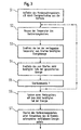
- the proportion e v of the energy stored in the capacitor which is branched off for the consumer, is plotted as a function of the temperature of the internal combustion engine.
- the proportion e v is defined as the ratio of the amount of energy E v diverted to the consumer and the amount of the total energy E total stored in the capacitor.
- T min the lowest occurring temperature
- T max the highest occurring temperature of the internal combustion engine
- only part of the stored energy is required for starting, ie the starting energy component e Start / warm is significantly less than one.
- the remaining amount of energy can be used to feed a consumer before starting, ie the consumer energy component e V / warm is equal to the difference between one and e Start / warm .
- 1 schematically illustrates e v for all values between T min and T max .
- a starter system for a motor vehicle, e.g. a passenger car, an internal combustion engine 1, the Torque via a drive shaft 2 (e.g. the crankshaft of the Internal combustion engine 1), a clutch 3 and others (not shown) Parts of a drive train on the drive wheels of the vehicle emits. With the starter function of interest here the clutch 3 opened.
- Electric machine 4 serving as a starter, here an asynchronous three-phase machine. It has one directly on the drive shaft 2 seated and rotatably connected runner 5 and one e.g. Stand 6 supported on the housing of the internal combustion engine 1 on.
- the starter 4 (as well as the facilities described in more detail below for its supply and for energy storage) are like this dimensioned that the internal combustion engine 1 preferably directly (i.e. without flywheel function or the like) can and preferably also no ratio or reduction between Starter 4 and internal combustion engine 1 is arranged so that both can run together permanently.
- the winding (not shown) of the stator 6 is by an inverter 7 with electrical Currents and voltages practically freely adjustable amplitude, Phase and frequency fed. It is e.g. a DC link inverter, which from a in essentially constant DC link voltage with the help of electronic switches e.g.
- the inverter is essentially a machine-side DC-AC converter 7a, an intermediate circuit 7b and a DC voltage converter 7c on the electrical system side.
- Short-term energy storage 8 e.g. a capacitor store
- the converter 7c is with a vehicle electrical system 9 and a long-term energy storage, here an electrical system battery 10, coupled.
- the electrical system 9 and the Battery 10 is at a low voltage level, e.g. 12 or 24 volts.
- the intermediate circuit 7b lies on a increased voltage, which is advantageously in the range between 48 and is 350 volts.
- the electrical machine 4 can after Starting process in which she needs electrical energy as a generator act, i.e. deliver electrical energy.
- the converter 7c is therefore designed as a bidirectional converter, on the one hand for the starting process or its preparation electrical energy bring from the on-board electrical system battery 10 into the intermediate circuit 7b can, and on the other hand in generator operation energy from the To transfer intermediate circuit 7b to the low voltage side Consumers of the electrical system 9 to feed and the electrical system battery 10 to load.
- the converter 7a converts the DC voltage during motor operation of the intermediate circuit 7b in AC voltage, in generator mode it feeds the one supplied by the electrical machine 4 Energy after rectification in the intermediate circuit 7b.
- the Capacitor memory 8 is able to generate voltage pulses with a for a high pulse frequency (advantageous in the range from 20 kHz to 100 kHz) with the required slope. He also serves as an energy store for those required to start Energy, possibly in cooperation with the battery 10. With others Embodiments (not shown) is for deployment flank divider Pulse a separate, particularly quickly unloadable Capacitor storage is provided, which is only lower Capacity.
- the charging of the capacitor store 8 can either in generator mode by the electrical Machine 4 via the converter 7a, or when the vehicle is at a standstill take place from the battery 10 via the converter 7c.
- High performance consumer e.g. an electric catalyst heater
- a consumer control device 12 with the DC link 7b coupled. Feeding the high-performance consumer 11 advantageously takes place at a high voltage level, e.g. the voltage level of the intermediate circuit 7b.
- the consumer control device 12 does not serve as a voltage converter, but only as a current control device. In other embodiments it also has the function of a voltage converter to higher ones or lower voltages.
- a higher-level control device 13 controls the inverter 7, namely the inverter 7a and the Converter 7c, as well as the consumer control device 12. It gives that Converter 7a amplitude, phase and frequency of the starter 4 to supplying three-phase current. The converter 7c gives the amount of current the current direction and the amount of the voltage increase or -reduction before. Finally, there is the consumer control device 12 what amount of current this from the intermediate circuit 7b and if necessary which voltage difference to overcome is.
- the controller 13 receives input signals from one Temperature sensor 14, the information e.g. about the coolant temperature of the internal combustion engine 1 delivers. It also receives Input signals from a rotary encoder (not shown) which it determine the current speed of the drive shaft 2 can. It can also receive a number of other information e.g. regarding the position of the throttle valve of the internal combustion engine 1, the ignition timing etc.
- step S1 the capacitor store 8 is charged.
- the charging takes place to a fixed predetermined value, e.g. through the The target value of the DC link voltage is specified.
- the capacitor store 8 is already charged with the internal combustion engine running then as a generator functioning electrical machine 4.
- the capacitor store 8 discharges gradually, so that it is then wholly or partially by taking energy is to be charged from the on-board electrical system battery 10.
- step S2 the control unit 13 determines the current temperature of the Internal combustion engine based on that supplied by the temperature sensor 14 Measurement information.
- step S3 the control device 13 determines e.g.
- step S4 Control unit 13 from whether a command to start the internal combustion engine - was given by pressing the ignition key. If this is not the case, the control unit 13 carries out the Steps S2 to S5 are repeated. If, however, a start command has been given, it proceeds to the following step S6.
- this is Program in a passive waiting state; only after receiving one Starting commands, it carries out actions in accordance with steps S2 and S4 through).
- the control device 13 causes the High-performance consumer 11, here a catalyst heater, with short term very high performance with the part of the Energy is fed.
- the catalyst immediately comes e.g. to operating temperature and is already at the first Ignitions ready for the material conversion of harmful exhaust gases.
- the internal combustion engine 1 is finally under Use of the energy portion remaining in the capacitor store 8 started.
- the invention is based on the idea that Temperature dependence of the amount of energy required to start not to be taken into account when charging the temporary storage device, but during the discharge process. This is particularly beneficial for such starter systems in which the short-term storage voltage should be at a predetermined level, such as that Intermediate circuit level of the starter supply serving inverter.
Landscapes
- Engineering & Computer Science (AREA)
- Chemical & Material Sciences (AREA)
- Combustion & Propulsion (AREA)
- Mechanical Engineering (AREA)
- General Engineering & Computer Science (AREA)
- Power Engineering (AREA)
- Charge And Discharge Circuits For Batteries Or The Like (AREA)
- Combined Controls Of Internal Combustion Engines (AREA)
Abstract
Claims (5)
- Système de démarrage pour un moteur à combustion interne (1) avec :un démarreur électrique (4),un accumulateur électrique de courte durée (8), en particulier un accumulateur à condensateur qui, après son chargement, sert à l'alimentation du démarreur (4),une saisie directe ou indirecte de la température etun dispositif de commande (13), qui déclenche un prélèvement d'une partie de l'énergie accumulée dans l'accumulateur de courte durée pour alimenter avant l'opération de démarrage un ou plusieurs consommateur(s) (11), l'importance de cette partie étant fonction de la température, c'est-à-dire moins importante aux basses températures qu'aux températures élevées.
- Système de démarrage selon la revendication 1, caractérisé en ce que le consommateur (11) est un chauffage électrique, en particulier un chauffage à catalyseur.
- Système de démarrage selon la revendication 1 ou 2, caractérisé en ce que le démarreur est alimenté par un onduleur (7) comprenant un circuit intermédiaire à tension continue (7b) et en ce que l'accumulateur de courte durée (8) se trouve dans le circuit intermédiaire à tension continue (7b).
- Procédé de démarrage d'un moteur à combustion interne (1) comprenant les étapes suivantes :chargement d'un accumulateur de courte durée (8) par prélèvement d'énergie dans un accumulateur de longue durée (10),saisie de la température et détermination de la quantité d'énergie qui est nécessaire pour le démarrage du moteur à combustion interne (1) à la température qui a été saisie,sur la base d'un ordre de démarrage, prélèvement de la partie de l'énergie accumulée qui n'est pas nécessaire pour le démarrage à la température qui a été saisie et injection de cette énergie dans un ou dans plusieurs consommateur(s) (11) etdémarrage du moteur à combustion interne (1) en utilisant la partie d'énergie qui est restée dans l'accumulateur de courte durée (8).
- Procédé selon la revendication 4, caractérisé en ce que le consommateur (11) est un chauffage électrique, en particulier un chauffage à catalyseur.
Applications Claiming Priority (3)
| Application Number | Priority Date | Filing Date | Title |
|---|---|---|---|
| DE19709298 | 1997-03-06 | ||
| DE19709298A DE19709298C2 (de) | 1997-03-06 | 1997-03-06 | Startersysteme für einen Verbrennungsmotor sowie Verfahren zum Starten eines Verbrennungsmotors |
| PCT/EP1998/001297 WO1998039565A1 (fr) | 1997-03-06 | 1998-03-06 | Systemes de demarrage pour moteur a combustion interne et procede de demarrage correspondant |
Publications (2)
| Publication Number | Publication Date |
|---|---|
| EP0964995A1 EP0964995A1 (fr) | 1999-12-22 |
| EP0964995B1 true EP0964995B1 (fr) | 2003-02-26 |
Family
ID=7822515
Family Applications (1)
| Application Number | Title | Priority Date | Filing Date |
|---|---|---|---|
| EP98913670A Expired - Lifetime EP0964995B1 (fr) | 1997-03-06 | 1998-03-06 | Systemes de demarrage pour moteur a combustion interne et procede de demarrage correspondant |
Country Status (5)
| Country | Link |
|---|---|
| US (1) | US6202615B1 (fr) |
| EP (1) | EP0964995B1 (fr) |
| JP (1) | JP2001513863A (fr) |
| DE (2) | DE19709298C2 (fr) |
| WO (1) | WO1998039565A1 (fr) |
Cited By (1)
| Publication number | Priority date | Publication date | Assignee | Title |
|---|---|---|---|---|
| WO2006069620A1 (fr) * | 2004-12-28 | 2006-07-06 | Volkswagen Aktiengesellschaft | Procede et dispositif permettant un demarrage optimise d'un moteur a combustion interne |
Families Citing this family (60)
| Publication number | Priority date | Publication date | Assignee | Title |
|---|---|---|---|---|
| DE19817497A1 (de) * | 1998-04-20 | 1999-10-28 | Isad Electronic Sys Gmbh & Co | Verfahren und Startersystem zum Starten eines Verbrennungsmotors |
| DE19847392B4 (de) * | 1998-10-14 | 2008-06-19 | Robert Bosch Gmbh | Bordnetz mit zwei unterschiedlichen Gleichspannungsniveaus |
| DE19859036A1 (de) * | 1998-12-24 | 2000-06-29 | Audi Ag | Bordnetz für ein Kraftfahrzeug |
| DE19917294B4 (de) * | 1999-04-16 | 2007-06-14 | Volkswagen Ag | Bordnetz für Kraftfahrzeuge |
| JP4064016B2 (ja) * | 1999-09-13 | 2008-03-19 | 本田技研工業株式会社 | 内燃機関の始動制御装置 |
| JP3775189B2 (ja) * | 1999-12-28 | 2006-05-17 | 国産電機株式会社 | 内燃機関用スタータジェネレータ |
| US6433990B1 (en) * | 2000-02-02 | 2002-08-13 | Nea Electronics, Inc. | Frangible actuator with redundant power supply |
| US6380701B1 (en) * | 2000-03-31 | 2002-04-30 | Visteon Global Tech., Inc. | Vehicle charge assembly |
| US6398511B1 (en) * | 2000-08-18 | 2002-06-04 | Bombardier Motor Corporation Of America | Fuel injection driver circuit with energy storage apparatus |
| US6420793B1 (en) * | 2000-09-21 | 2002-07-16 | Ford Global Technologies, Inc. | Power delivery circuit with boost for energetic starting in a pulsed charge starter/alternator system |
| US6717291B2 (en) * | 2000-10-10 | 2004-04-06 | Purkey's Electrical Consulting | Capacitor-based powering system and associated methods |
| DE10103995A1 (de) * | 2001-01-30 | 2002-08-22 | Epcos Ag | Bordstromspeicher 12Volt und/oder 42Volt Kfz-Bordnetze sowie Vorrichtung zum Starten |
| DE10116463A1 (de) | 2001-04-03 | 2002-10-10 | Isad Electronic Sys Gmbh & Co | System zur Speicherung von elektrischer Energie, sowie Verfahren zum Betreiben eines solchen Energiespeichersystems |
| US6616573B2 (en) | 2001-09-21 | 2003-09-09 | Club Car, Inc. | Method and apparatus for eliminating power drainage in power sources used with starter-generators |
| JP3750608B2 (ja) * | 2002-01-23 | 2006-03-01 | トヨタ自動車株式会社 | 車両における蓄電装置の制御装置 |
| DE10231379B3 (de) * | 2002-05-24 | 2004-01-15 | Daimlerchrysler Ag | Antriebssystem für ein Kraftfahrzeug mit einem Verbrennungsmotor und einer elektrischen Maschine |
| DE10231091A1 (de) | 2002-07-10 | 2004-01-22 | Robert Bosch Gmbh | Aktivgleichrichter-Modul für Drehstromgeneratoren von Fahrzeugen |
| EP1424494A1 (fr) * | 2002-11-27 | 2004-06-02 | Continental ISAD Electronic Systems GmbH & Co. oHG | Dispositif de propulsion hybride et méthode pour l'application commune d'un couple de propulsion |
| DE10259879A1 (de) * | 2002-12-20 | 2004-07-01 | Zf Friedrichshafen Ag | Schaltungsanordnung zur Bereitstellung von Energie an elektrische Verbraucher unterschiedlichen Energiebedarfs |
| CN100444495C (zh) * | 2003-01-24 | 2008-12-17 | 三菱电机株式会社 | 电池用电力电路 |
| JP4120418B2 (ja) * | 2003-02-17 | 2008-07-16 | 株式会社デンソー | 自動車用電源装置 |
| EP2154028B8 (fr) * | 2003-02-17 | 2015-12-09 | Denso Corporation | Système d'alimentation électrique de véhicule |
| US7342382B1 (en) | 2004-02-03 | 2008-03-11 | Dana Corporation | Method of determining transition from starter to alternator function by monitoring battery voltage or current |
| DE502004005073D1 (de) * | 2004-02-16 | 2007-11-08 | Catem Develec Gmbh | Kraftfahrzeug-Bordnetz mit einem Spannungswandler |
| US7319306B1 (en) | 2004-06-25 | 2008-01-15 | Sure Power Industries, Inc. | Supercapacitor engine starting system with charge hysteresis |
| US7107956B2 (en) * | 2004-07-30 | 2006-09-19 | Ford Global Technologies, Llc | Vehicle and method for controlling engine start in a vehicle |
| JP4320630B2 (ja) * | 2004-10-22 | 2009-08-26 | 株式会社デンソー | エンジン制御システム |
| WO2006083977A1 (fr) * | 2005-02-02 | 2006-08-10 | Brp Us Inc. | Methode de commande d'un assemblage de pompage |
| ITRM20050055U1 (it) * | 2005-05-02 | 2006-11-03 | Enea Ente Nuove Tec | Sistema di accumulo energetico integrato. |
| US7278388B2 (en) * | 2005-05-12 | 2007-10-09 | Ford Global Technologies, Llc | Engine starting for engine having adjustable valve operation |
| US8210145B2 (en) * | 2005-05-17 | 2012-07-03 | Panasonic Corporation | Engine start device |
| FR2888891B1 (fr) * | 2005-07-19 | 2010-09-17 | Valeo Equip Electr Moteur | Dispositif de demarrage d'un moteur a combustion interne, en particulier d'un moteur diesel |
| US7267090B2 (en) * | 2005-11-21 | 2007-09-11 | Gm Global Technology Operations, Inc. | Method of starting a hybrid vehicle |
| WO2008034958A1 (fr) * | 2006-09-22 | 2008-03-27 | Valeo Equipements Electriques Moteur | Dispositif de demarrage d'un moteur a combustion interne, en particulier d'un moteur diesel |
| FR2912190B1 (fr) * | 2007-02-07 | 2013-06-14 | Peugeot Citroen Automobiles Sa | Procede de demarrage du moteur thermique d'un vehicule automobile hybride |
| CA2677940C (fr) * | 2007-02-16 | 2013-10-22 | Universal Supercapacitors Llc | Supracondensateur electromecanique/dispositif hybride de stockage d'energie electrique a batterie au plomb |
| US8134343B2 (en) * | 2007-04-27 | 2012-03-13 | Flextronics International Kft | Energy storage device for starting engines of motor vehicles and other transportation systems |
| US7761198B2 (en) * | 2007-06-25 | 2010-07-20 | General Electric Company | Methods and systems for power system management |
| US7889524B2 (en) | 2007-10-19 | 2011-02-15 | Illinois Institute Of Technology | Integrated bi-directional converter for plug-in hybrid electric vehicles |
| FR2933357B1 (fr) * | 2008-07-02 | 2011-02-11 | Peugeot Citroen Automobiles Sa | Systeme de gestion electrique multi tension pour vehicule hybride. |
| FR2935156A1 (fr) * | 2008-08-25 | 2010-02-26 | Peugeot Citroen Automobiles Sa | Procede et dispositif de demarrage d'un moteur thermique, support d'enregistrement pour ce procede et vehicule equipe de ce dispositif. |
| DE102009006665A1 (de) * | 2009-01-29 | 2010-08-05 | Dr. Ing. H.C. F. Porsche Aktiengesellschaft | Bordnetz eines Kraftfahrzeuges und zugehöriges Betriebsverfahren |
| DE102009007545A1 (de) | 2009-02-04 | 2010-08-05 | Wenzl, Heinz, Dr. | Starthilfesystem |
| JP2010270747A (ja) * | 2009-04-23 | 2010-12-02 | Denso Corp | エンジン自動制御装置 |
| DE102009027398A1 (de) * | 2009-07-01 | 2011-01-05 | Robert Bosch Gmbh | Startvorrichtung für eine Brennkraftmaschine und Verfahren zum Betreiben einer Startvorrichtung |
| DE102009027407A1 (de) * | 2009-07-01 | 2011-01-05 | Robert Bosch Gmbh | Verfahren zum Betreiben einer Startersteuerung, Computerprogrammprodukt und Startersteuerung |
| DE102009029526B4 (de) * | 2009-09-17 | 2019-07-18 | Seg Automotive Germany Gmbh | Verfahren zum Betreiben einer Starteranlage |
| WO2011143743A1 (fr) * | 2010-05-18 | 2011-11-24 | Canadian Energy Efficiency Alliance | Système, appareil, et procédé de réduction du fonctionnement au ralenti de véhicules |
| FR2964708B1 (fr) * | 2010-09-15 | 2012-08-24 | Peugeot Citroen Automobiles Sa | Procede de commande d'une interface homme-machine d'un vehicule automobile |
| FR2965309B1 (fr) * | 2010-09-29 | 2012-08-31 | Peugeot Citroen Automobiles Sa | Procede de gestion de l'arret et du redemarrage automatique d'un moteur thermique de vehicule automobile et vehicule automobile correspondant |
| FR2966205B1 (fr) * | 2010-10-19 | 2018-01-12 | Psa Automobiles Sa. | Procede pour la mise en œuvre d'un dispositif de demarrage equipant un moteur d'un vehicule automobile |
| FI123903B (en) * | 2012-10-24 | 2013-12-13 | Waertsilae Finland Oy | Internal combustion engine fluid detection system |
| US10119514B2 (en) | 2015-05-05 | 2018-11-06 | Ariel—University Research and Development Company Ltd. | Ultracapacitor-based power source |
| US10876510B2 (en) | 2016-03-02 | 2020-12-29 | Gentherm Incorporated | Systems and methods for supplying power in a hybrid vehicle using capacitors, a battery and one or more DC/DC converters |
| US10124793B2 (en) * | 2016-03-02 | 2018-11-13 | Gentherm Incorporated | Systems and methods for supplying power in a hybrid vehicle using capacitors, a battery and one or more DC/DC converters |
| US10886583B2 (en) | 2016-03-02 | 2021-01-05 | Gentherm Incorporated | Battery and capacitor assembly for a vehicle and a method for heating and cooling the battery and capacitor assembly |
| JP6881341B2 (ja) * | 2018-01-31 | 2021-06-02 | トヨタ自動車株式会社 | 車両の制御装置 |
| JP7124619B2 (ja) | 2018-10-04 | 2022-08-24 | トヨタ自動車株式会社 | エンジンの始動装置およびエンジンの始動方法 |
| DE102019126449A1 (de) * | 2019-10-01 | 2021-04-01 | Toyota Jidosha Kabushiki Kaisha | Maschinenanlasser und Maschinenanlassverfahren |
| US11342776B2 (en) | 2020-06-15 | 2022-05-24 | Magnetic Energy Charging, Inc. | Battery charger and method for charging a battery |
Family Cites Families (20)
| Publication number | Priority date | Publication date | Assignee | Title |
|---|---|---|---|---|
| FR1469141A (fr) | 1965-12-28 | 1967-02-10 | Accumulateurs Fixes | Installation électrique d'alimentation pour véhicules et engins à moteur à combustion interne |
| DE3713835A1 (de) | 1987-04-24 | 1988-11-03 | Beru Werk Ruprecht Gmbh Co A | Verfahren und vorrichtung zum schnellaufheizen einer elektrischen heizvorrichtung |
| DE3743317A1 (de) | 1987-12-21 | 1989-06-29 | Bosch Gmbh Robert | Fahrzeugbordnetzsystem |
| US5175439A (en) | 1987-12-21 | 1992-12-29 | Robert Bosch Gmbh | Power supply circuit for motor vehicles |
| JP2518368B2 (ja) | 1988-12-27 | 1996-07-24 | いすゞ自動車株式会社 | 車両用電源装置 |
| JPH02175351A (ja) | 1988-12-27 | 1990-07-06 | Isuzu Motors Ltd | 車両用補助電源 |
| JPH02259277A (ja) | 1989-03-31 | 1990-10-22 | Isuzu Motors Ltd | エンジン始動装置 |
| JP2522060B2 (ja) * | 1989-06-14 | 1996-08-07 | いすゞ自動車株式会社 | エンジン始動装置 |
| JPH0669270B2 (ja) | 1989-08-10 | 1994-08-31 | いすゞ自動車株式会社 | コンデンサの充電装置 |
| JPH03117685A (ja) | 1989-09-29 | 1991-05-20 | Isuzu Motors Ltd | エンジン予熱装置 |
| DE4028242C2 (de) | 1990-09-06 | 1997-08-07 | Bayerische Motoren Werke Ag | Bordnetz für Kraftfahrzeuge |
| IT1247766B (it) | 1990-10-25 | 1994-12-30 | Magneti Marelli Spa | Sistema di avviamento per un motore a combustione interna per autoveicoli |
| IT1251206B (it) * | 1991-09-18 | 1995-05-04 | Magneti Marelli Spa | Impianto elettrico di un autoveicolo, comprendente almeno un supercondensatore. |
| DE4138943C1 (fr) * | 1991-11-27 | 1993-05-27 | Robert Bosch Gmbh, 7000 Stuttgart, De | |
| JP3228001B2 (ja) * | 1994-05-11 | 2001-11-12 | いすゞ自動車株式会社 | エンジン始動装置 |
| DE4422256A1 (de) | 1994-06-24 | 1996-01-04 | Bayerische Motoren Werke Ag | Bordnetz für ein Kraftfahrzeug |
| DE4422231C2 (de) * | 1994-06-24 | 1997-08-28 | Bayerische Motoren Werke Ag | Bordnetz für ein Kraftfahrzeug |
| DE19541001A1 (de) | 1995-08-14 | 1997-02-20 | Holger Voigt | Vorglüheinrichtung |
| EP0876554B2 (fr) | 1995-08-31 | 2007-01-24 | TEMIC Automotive Electric Motors GmbH | Demarreur/generateur pour moteur a combustion interne, notamment d'automobile |
| DE19532163A1 (de) | 1995-08-31 | 1997-03-06 | Clouth Gummiwerke Ag | System zur aktiven Verringerung von Drehungleichförmigkeiten einer Welle, insbesondere der Triebwelle eines Verbrennungsmotors, und Verfahren hierzu |
-
1997
- 1997-03-06 DE DE19709298A patent/DE19709298C2/de not_active Revoked
-
1998
- 1998-03-06 EP EP98913670A patent/EP0964995B1/fr not_active Expired - Lifetime
- 1998-03-06 JP JP53817598A patent/JP2001513863A/ja active Pending
- 1998-03-06 WO PCT/EP1998/001297 patent/WO1998039565A1/fr active IP Right Grant
- 1998-03-06 DE DE59807311T patent/DE59807311D1/de not_active Expired - Fee Related
-
1999
- 1999-09-03 US US09/389,992 patent/US6202615B1/en not_active Expired - Lifetime
Cited By (1)
| Publication number | Priority date | Publication date | Assignee | Title |
|---|---|---|---|---|
| WO2006069620A1 (fr) * | 2004-12-28 | 2006-07-06 | Volkswagen Aktiengesellschaft | Procede et dispositif permettant un demarrage optimise d'un moteur a combustion interne |
Also Published As
| Publication number | Publication date |
|---|---|
| DE19709298A1 (de) | 1998-09-24 |
| DE59807311D1 (de) | 2003-04-03 |
| EP0964995A1 (fr) | 1999-12-22 |
| JP2001513863A (ja) | 2001-09-04 |
| DE19709298C2 (de) | 1999-03-11 |
| US6202615B1 (en) | 2001-03-20 |
| WO1998039565A1 (fr) | 1998-09-11 |
Similar Documents
| Publication | Publication Date | Title |
|---|---|---|
| EP0964995B1 (fr) | Systemes de demarrage pour moteur a combustion interne et procede de demarrage correspondant | |
| EP1112447B1 (fr) | Systeme de demarreur pour un moteur a combustion interne et procede de demarrage dudit moteur | |
| EP0847487B2 (fr) | Systeme d'entrainement avec moteur d'entrainement, moteur electrique et batterie | |
| EP0961874B1 (fr) | Systeme de propulsion, notamment automobile, et moyen de contrecarrer une modification du regime de ralenti dans un systeme de propulsion | |
| EP1073842B1 (fr) | Procede et systeme pour le demarrage d'un moteur a combustion interne | |
| EP1676738B1 (fr) | Méthode et dispositif de commande pour les moyens de stockage d'énergie électrique pour un véhicule hybride | |
| EP2576303B1 (fr) | Procédé pour faire fonctionner un système, système, commande et produit de programme d'ordinateur | |
| EP0964996B1 (fr) | Auxiliaire de demarrage pour moteur diesel et procede de demarrage d'un moteur diesel | |
| EP1013506A2 (fr) | Réseau de bord d'un véhicule | |
| DE10148248A1 (de) | Verfahren und elektrisches System zum energiereichen Anlassen eines Motors eines Kraftfahrzeuges | |
| DE4223854A1 (de) | Vorrichtung zur energieversorgung von kraftfahrzeugteilen | |
| DE10202237B4 (de) | Verfahren und Vorrichtung zur Steuerung einer induktions-Maschine | |
| DE19809399C2 (de) | Startanlage für einen Dieselmotor | |
| EP1313628B1 (fr) | Procede permettant de faire fonctionner un mecanisme d'entrainement avec un moteur a combustion interne et une machine electrique | |
| EP1283580B1 (fr) | Circuit de symmetrization, procédé de symmetrization de tension et système d'entraînement pour un véhicule | |
| DE10008287B4 (de) | Fahrzeug-Antriebssystem und Verfahren zum Betreiben eines Fahrzeug-Antriebssystems | |
| DE60115747T2 (de) | Vorrichtung zur Erzeugung von Wechselstrom für Kraftfahrzeuge | |
| EP1000242B1 (fr) | Procede permettant de faire demarrer un moteur diesel et systeme d'entrainement comportant ledit moteur | |
| EP1469586B1 (fr) | Appareil pour améliorer le fonctionnement d'arrêt et de redémarrage d'un véhicule | |
| DE102009000121A1 (de) | Antriebsanordnung für ein Kraftfahrzeug |
Legal Events
| Date | Code | Title | Description |
|---|---|---|---|
| PUAI | Public reference made under article 153(3) epc to a published international application that has entered the european phase |
Free format text: ORIGINAL CODE: 0009012 |
|
| 17P | Request for examination filed |
Effective date: 19990803 |
|
| AK | Designated contracting states |
Kind code of ref document: A1 Designated state(s): DE FR GB IT |
|
| RIN1 | Information on inventor provided before grant (corrected) |
Inventor name: ZEYEN, KLAUS-PETER Inventor name: RIEKENBRAUCK, HOLGER Inventor name: REVERMANN, KLAUS Inventor name: PELS, THOMAS |
|
| RAP1 | Party data changed (applicant data changed or rights of an application transferred) |
Owner name: CONTINENTAL ISAD ELECTRONIC SYSTEMS GMBH & CO. OHG |
|
| 17Q | First examination report despatched |
Effective date: 20010510 |
|
| GRAG | Despatch of communication of intention to grant |
Free format text: ORIGINAL CODE: EPIDOS AGRA |
|
| GRAG | Despatch of communication of intention to grant |
Free format text: ORIGINAL CODE: EPIDOS AGRA |
|
| GRAH | Despatch of communication of intention to grant a patent |
Free format text: ORIGINAL CODE: EPIDOS IGRA |
|
| GRAH | Despatch of communication of intention to grant a patent |
Free format text: ORIGINAL CODE: EPIDOS IGRA |
|
| GRAA | (expected) grant |
Free format text: ORIGINAL CODE: 0009210 |
|
| AK | Designated contracting states |
Designated state(s): DE FR GB IT |
|
| REG | Reference to a national code |
Ref country code: GB Ref legal event code: FG4D Free format text: NOT ENGLISH |
|
| REF | Corresponds to: |
Ref document number: 59807311 Country of ref document: DE Date of ref document: 20030403 Kind code of ref document: P |
|
| GBT | Gb: translation of ep patent filed (gb section 77(6)(a)/1977) | ||
| ET | Fr: translation filed | ||
| PLBE | No opposition filed within time limit |
Free format text: ORIGINAL CODE: 0009261 |
|
| STAA | Information on the status of an ep patent application or granted ep patent |
Free format text: STATUS: NO OPPOSITION FILED WITHIN TIME LIMIT |
|
| 26N | No opposition filed |
Effective date: 20031127 |
|
| PGFP | Annual fee paid to national office [announced via postgrant information from national office to epo] |
Ref country code: DE Payment date: 20060314 Year of fee payment: 9 |
|
| PGFP | Annual fee paid to national office [announced via postgrant information from national office to epo] |
Ref country code: IT Payment date: 20060331 Year of fee payment: 9 |
|
| GBPC | Gb: european patent ceased through non-payment of renewal fee |
Effective date: 20070306 |
|
| PG25 | Lapsed in a contracting state [announced via postgrant information from national office to epo] |
Ref country code: DE Free format text: LAPSE BECAUSE OF NON-PAYMENT OF DUE FEES Effective date: 20071002 |
|
| PG25 | Lapsed in a contracting state [announced via postgrant information from national office to epo] |
Ref country code: GB Free format text: LAPSE BECAUSE OF NON-PAYMENT OF DUE FEES Effective date: 20070306 |
|
| REG | Reference to a national code |
Ref country code: FR Ref legal event code: TP |
|
| PGFP | Annual fee paid to national office [announced via postgrant information from national office to epo] |
Ref country code: GB Payment date: 20060322 Year of fee payment: 9 |
|
| PG25 | Lapsed in a contracting state [announced via postgrant information from national office to epo] |
Ref country code: IT Free format text: LAPSE BECAUSE OF NON-PAYMENT OF DUE FEES Effective date: 20070306 |
|
| REG | Reference to a national code |
Ref country code: FR Ref legal event code: PLFP Year of fee payment: 19 |
|
| REG | Reference to a national code |
Ref country code: FR Ref legal event code: PLFP Year of fee payment: 20 |
|
| PGFP | Annual fee paid to national office [announced via postgrant information from national office to epo] |
Ref country code: FR Payment date: 20170322 Year of fee payment: 20 |