EP1000242B1 - Procede permettant de faire demarrer un moteur diesel et systeme d'entrainement comportant ledit moteur - Google Patents
Procede permettant de faire demarrer un moteur diesel et systeme d'entrainement comportant ledit moteur Download PDFInfo
- Publication number
- EP1000242B1 EP1000242B1 EP98945105A EP98945105A EP1000242B1 EP 1000242 B1 EP1000242 B1 EP 1000242B1 EP 98945105 A EP98945105 A EP 98945105A EP 98945105 A EP98945105 A EP 98945105A EP 1000242 B1 EP1000242 B1 EP 1000242B1
- Authority
- EP
- European Patent Office
- Prior art keywords
- diesel engine
- speed
- starter
- starting
- temperature
- Prior art date
- Legal status (The legal status is an assumption and is not a legal conclusion. Google has not performed a legal analysis and makes no representation as to the accuracy of the status listed.)
- Expired - Lifetime
Links
- 239000007858 starting material Substances 0.000 claims abstract description 42
- 238000000034 method Methods 0.000 claims abstract description 24
- 239000000446 fuel Substances 0.000 claims abstract description 14
- 239000003990 capacitor Substances 0.000 claims description 15
- 238000002485 combustion reaction Methods 0.000 claims description 12
- 238000002347 injection Methods 0.000 claims description 5
- 239000007924 injection Substances 0.000 claims description 5
- 239000003795 chemical substances by application Substances 0.000 abstract 2
- 238000010438 heat treatment Methods 0.000 description 7
- 230000006835 compression Effects 0.000 description 5
- 238000007906 compression Methods 0.000 description 5
- 238000001816 cooling Methods 0.000 description 2
- 239000000498 cooling water Substances 0.000 description 2
- 230000002457 bidirectional effect Effects 0.000 description 1
- 230000005540 biological transmission Effects 0.000 description 1
- 230000001419 dependent effect Effects 0.000 description 1
- 238000006073 displacement reaction Methods 0.000 description 1
- 230000000694 effects Effects 0.000 description 1
- 230000007613 environmental effect Effects 0.000 description 1
- 230000006698 induction Effects 0.000 description 1
- 230000007774 longterm Effects 0.000 description 1
- 238000005259 measurement Methods 0.000 description 1
- 239000000779 smoke Substances 0.000 description 1
- QAOWNCQODCNURD-UHFFFAOYSA-N sulfuric acid Substances OS(O)(=O)=O QAOWNCQODCNURD-UHFFFAOYSA-N 0.000 description 1
- 238000004804 winding Methods 0.000 description 1
Images

Classifications
-
- F—MECHANICAL ENGINEERING; LIGHTING; HEATING; WEAPONS; BLASTING
- F02—COMBUSTION ENGINES; HOT-GAS OR COMBUSTION-PRODUCT ENGINE PLANTS
- F02N—STARTING OF COMBUSTION ENGINES; STARTING AIDS FOR SUCH ENGINES, NOT OTHERWISE PROVIDED FOR
- F02N11/00—Starting of engines by means of electric motors
- F02N11/08—Circuits or control means specially adapted for starting of engines
-
- F—MECHANICAL ENGINEERING; LIGHTING; HEATING; WEAPONS; BLASTING
- F02—COMBUSTION ENGINES; HOT-GAS OR COMBUSTION-PRODUCT ENGINE PLANTS
- F02D—CONTROLLING COMBUSTION ENGINES
- F02D41/00—Electrical control of supply of combustible mixture or its constituents
- F02D41/02—Circuit arrangements for generating control signals
- F02D41/04—Introducing corrections for particular operating conditions
- F02D41/06—Introducing corrections for particular operating conditions for engine starting or warming up
- F02D41/062—Introducing corrections for particular operating conditions for engine starting or warming up for starting
-
- F—MECHANICAL ENGINEERING; LIGHTING; HEATING; WEAPONS; BLASTING
- F02—COMBUSTION ENGINES; HOT-GAS OR COMBUSTION-PRODUCT ENGINE PLANTS
- F02N—STARTING OF COMBUSTION ENGINES; STARTING AIDS FOR SUCH ENGINES, NOT OTHERWISE PROVIDED FOR
- F02N11/00—Starting of engines by means of electric motors
- F02N11/04—Starting of engines by means of electric motors the motors being associated with current generators
-
- F—MECHANICAL ENGINEERING; LIGHTING; HEATING; WEAPONS; BLASTING
- F02—COMBUSTION ENGINES; HOT-GAS OR COMBUSTION-PRODUCT ENGINE PLANTS
- F02N—STARTING OF COMBUSTION ENGINES; STARTING AIDS FOR SUCH ENGINES, NOT OTHERWISE PROVIDED FOR
- F02N11/00—Starting of engines by means of electric motors
- F02N11/08—Circuits or control means specially adapted for starting of engines
- F02N11/0862—Circuits or control means specially adapted for starting of engines characterised by the electrical power supply means, e.g. battery
- F02N11/0866—Circuits or control means specially adapted for starting of engines characterised by the electrical power supply means, e.g. battery comprising several power sources, e.g. battery and capacitor or two batteries
-
- F—MECHANICAL ENGINEERING; LIGHTING; HEATING; WEAPONS; BLASTING
- F02—COMBUSTION ENGINES; HOT-GAS OR COMBUSTION-PRODUCT ENGINE PLANTS
- F02N—STARTING OF COMBUSTION ENGINES; STARTING AIDS FOR SUCH ENGINES, NOT OTHERWISE PROVIDED FOR
- F02N2200/00—Parameters used for control of starting apparatus
- F02N2200/02—Parameters used for control of starting apparatus said parameters being related to the engine
- F02N2200/022—Engine speed
-
- F—MECHANICAL ENGINEERING; LIGHTING; HEATING; WEAPONS; BLASTING
- F02—COMBUSTION ENGINES; HOT-GAS OR COMBUSTION-PRODUCT ENGINE PLANTS
- F02N—STARTING OF COMBUSTION ENGINES; STARTING AIDS FOR SUCH ENGINES, NOT OTHERWISE PROVIDED FOR
- F02N2200/00—Parameters used for control of starting apparatus
- F02N2200/02—Parameters used for control of starting apparatus said parameters being related to the engine
- F02N2200/023—Engine temperature
-
- F—MECHANICAL ENGINEERING; LIGHTING; HEATING; WEAPONS; BLASTING
- F02—COMBUSTION ENGINES; HOT-GAS OR COMBUSTION-PRODUCT ENGINE PLANTS
- F02N—STARTING OF COMBUSTION ENGINES; STARTING AIDS FOR SUCH ENGINES, NOT OTHERWISE PROVIDED FOR
- F02N2300/00—Control related aspects of engine starting
- F02N2300/10—Control related aspects of engine starting characterised by the control output, i.e. means or parameters used as a control output or target
- F02N2300/102—Control of the starter motor speed; Control of the engine speed during cranking
Definitions
- the present invention relates to a method for starting of a diesel engine and a drive system of a motor vehicle with a diesel engine.
- Start-up aids are usually used in small-volume vehicles DI engines as well as engines with split combustion chamber glow plugs used.
- the glow plug of the candle protrudes into the combustion chamber or in the chamber of the engine.
- glow plugs are also Glow plugs (in the narrower sense) common, i.e. Glow plugs with exposed Filament.
- the thermal jump start often on preheating the suction Air with the help of electrically heated spark plugs or Heating flanges (see Automotive Engineering Handbook, 22. Ed. 1995, VDI-Verlag, Düsseldorf, pp. 538-540).
- JP 55-75568 describes a starter device for diesel engines known, when starting at low temperatures initially no air is let into the combustion chamber, which means the starter's workload is reduced and as a result the Starting speed increased. To preheat it then to Glow plugs are provided to start let-in air.
- a flywheel starter is known from DE 28 53 130 A1, the before starting with the help of an electric drive is brought to such a high speed that the stored kinetic energy is sufficient to start. at low temperatures will have a greater starting energy than at high, the flywheel is correspondingly lower Temperatures brought to higher speed.
- the aspect of a thermal jump start is in this document in which it primarily a special type of flywheel drive goes, not mentioned.
- the object of the present invention is an improved method to specify a diesel engine to start and a corresponding To provide drive system.
- the invention is based on the idea that by reducing the contact time between air and cylinder walls a significant improvement in the misfire start behavior can be achieved.
- the shorter contact time in turn is achieved by a faster starting speed.
- the compression when starting more adiabatic Area so that for the auto-ignition of the fuel required limit temperature even at low temperatures is achieved solely by compression.
- thermal jump starters such as glow plugs or Air preheating devices in the intake tract can be completely or at least above a low limit temperature.
- the diesel engine therefore has no thermal Jump starter on or it is controlled so that a any starting aid, if any, or only above the low limit temperature is used.
- a any starting aid if any, or only above the low limit temperature is used.
- the diesel engine therefore preferably has no such device for indirect preheating or is controlled so that such Device for starting not or only above the deep one Limit temperature is used.
- a post-heating device e.g. an after-glow device
- Such heating after starting is not considered “using a thermal Starting aids "to understand.
- the present invention thus makes a contribution on traffic safety, environmental protection and increasing the Driving comfort and to reduce effort in diesel vehicles. It can thus be used for the further spread of diesel vehicles contribute.
- Claims 5 and 8 relate to the point in time in the course fuel is injected during the starting process. And that is done this is advantageous only after the speed has been reached is necessary for self-ignition of the fuel. This saves Fuel and reduces smoke.
- the diesel engine is preferably a small-volume engine with a displacement of less than 3000 cm 3 , particularly preferably less than 2000 cm 3 .
- This type of engine is used in particular in passenger cars and small commercial vehicles with a total weight of less than 3.5 t.
- the cooling in the combustion chamber is particularly pronounced, and the omission of thermal starting aids achieved by the invention is therefore particularly advantageous here.
- the starter of the drive system is a direct starter, i.e. he brings the power required to start instantaneously (i.e. without storage) by converting electrical energy into mechanical Energy on. So it's not one Flywheel starter, the drive of which is not what is required to start Can apply torque, so that the drive Start only indirectly due to the storage of kinetic energy is possible.
- the starter is a as Starter / generator functioning electrical machine that is permanent runs along, unlike a flywheel starter before starting but does not have a driving effect.
- the relative speed of electrical Machine to diesel engine is in starter and generator operation same, i.e. the transmission ratio between electrical Machine and internal combustion engine are constant.
- Such Machines are designed for generator operation at high speeds. For starter operation, they have to be able to, high Applying torques. They are required to achieve the required excellent starting speed.
- Claim 11 is an electric starter inverter-controlled induction machine. Under "Rotary field machine” is understood to mean a machine in which a magnetic rotating field occurs, which rotates through 360 ° and thereby takes the runner with him.
- the inverter provides for the generation of the rotating field alternating or three-phase with freely adjustable Frequency, amplitude and phase ready.
- the energy required to start is at least partially a capacitor store (e.g. a so-called intermediate circuit store) removed, the subpoena according to claim 13 can take place depending on the temperature.
- the Energy for starting at least partially taken from a battery.
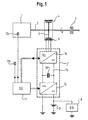
- the drive system according to Fig. 1 is e.g. for a motor vehicle, determined about a passenger car. It has a direct injection diesel engine with a small cubic capacity (e.g. 1500cm) 1 on, the torque via a drive shaft 2, a clutch 3 and other (not shown) parts of a drive train delivers the drive wheels of the vehicle.
- the diesel engine 1 is with no glow device and no preheating device equipped for the intake air. He also has no institution for heating the cooling water with the engine stopped.
- On the Drive shaft 2 is an electrical one serving as a starter / generator Machine 4, here an asynchronous three-phase machine, arranged. It has a seated directly on the drive shaft 2 and rotatably connected runner 5 and one e.g.
- the (not shown) winding of the stator 6 is by a Inverter 7 with electrical currents and voltages fed practically freely adjustable amplitude, phase and frequency. It is a DC link inverter, which is essentially one constant DC link voltage with the help of electronic Switches e.g. sine-weighted, wide-modulated pulses cuts out the - averaged by the inductance of the electrical machine 4 - to almost sinusoidal currents desired frequency, amplitude and phase.
- the inverter is essentially made up of a machine DC-AC converter 7a, one DC voltage intermediate circuit 7b and an electrical system side DC converter 7c constructed.
- the latter is with one Vehicle electrical system 8 and an electrical system long-term storage 9, here a conventional lead-sulfuric acid battery.
- the Vehicle electrical system 8 and the vehicle electrical system battery 9 are at a low level Voltage level, e.g. 12 or 24 volts.
- the intermediate circuit 7b on the other hand is due to an increased voltage, which is advantageous is in the range between 200 and 400 volts. With others Embodiments, the increased voltage is at the top of the low voltage range, around 36 volts.
- the intermediate circuit 7b is a short-term storage, here a capacitor storage 10 switched, which also the voltage in the intermediate circuit with a steep slope increasing current draw - the when pulses are generated by the converter 7a - approximately keeps constant.
- a short-term battery i.e. a quick-discharge battery
- the electrical machine 4 and the inverter 7 are like this designed to have the required torque and the necessary Power for directly driving the drive shaft 2 (e.g. the Crankshaft) of the diesel engine 1 to the required high Apply speed.
- the electrical machine 4 can, for example, after the starting process act as a generator, i.e. electrical power deliver.
- the converter 7c is a bidirectional converter educated. On the one hand, it can if the electrical machine 4 is operated as a motor and from the on-board electrical system battery 9 is fed, electrical energy from the electrical system battery 9 bring in the intermediate circuit 7b, and on the other hand if they as Generator is operated, energy from the intermediate circuit 7b for the purpose of feeding the consumers of the vehicle electrical system 8 and the vehicle electrical system battery 9 convict.
- the capacitor store 10 can also be used as an energy store for all or part of that required for starter operation Serve energy.
- the charging of the capacitor store 10 can be done in different ways: There is one possibility therein, the capacitor storage 10 even when the To keep diesel engine 1 charged: When operating the Diesel engine 1, i.e. in generator operation of the electrical machine 4 it will be charged anyway. When the engine stops the unavoidable slight charge losses are continuously recharged from the on-board electrical system battery 9. The start can then be done without waiting. Another one Reloading is not possible.
- the capacitor store 10 then discharges when the engine is at a standstill, and only from the on-board electrical system battery 9 before starting charged. In both cases, the whole does not need to Start required energy stored in the capacitor store 10 his.
- Embodiments takes a separate, with the Intermediate circuit 7b coupled energy store (e.g. a capacitor store or a short-term battery) storing the all or part of the starting energy. If at deep Temperatures a thermal starting aid for use comes, it is also advantageously from the capacitor store 10 fed. In embodiments (not shown) the supply of the starter 4 and possibly the thermal Starting aids wholly or partly from a battery, e.g. the on-board electrical system battery 9.
- the Intermediate circuit 7b coupled energy store e.g. a capacitor store or a short-term battery
- a higher-level control unit 11 controls the starting process by it the inverter 7, namely the converter 7a and the Converter 7c controls. It gives the converter 7a amplitude, phase and frequency of the three-phase voltage to be generated. the There is converter 7c the amount of current, the current direction for motor Operation and, if applicable, the amount of voltage increase (if energy is taken from the on-board electrical system battery 9).
- the control unit 11 controls the electrical Machine 4 via the inverter 7 such that the Drive shaft 2 to a high enough to ignite the fuel Speed is driven, not by one thermal booster system is made use of.
- the speed at which the diesel engine 1 from the electrical Machine 4 is driven (at least in a partial area) selected depending on temperature.
- an engine temperature sensor 12a and an outside temperature sensor 12 b provided to record the engine and outside temperature.
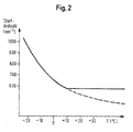
- Fig. 2 illustrates the dependence of the starting speed (ie the speed required for self-ignition, at which fuel is injected) on the temperature.
- the engine and outside temperature are assumed to be the same; Different values of these temperatures are taken into account by a corresponding map.
- the dependency drawn is such that the starting speed drops from a maximum (eg 400 min -1 ) at the lowest temperature with increasing temperature. Above a certain temperature (here 10 ° C) it is kept constant, ie it is in this area by an amount increasing with increasing temperature above the minimum required speed value. This setting of a minimum speed serves for starting comfort.
- a further temperature-dependent parameter can be the starting time, ie the time with which the diesel engine 1 is driven at the starting speed until fuel is injected.
- the start time is longer at low temperatures than at high ones, ie their temperature dependence is similar to the relationship shown in FIG. 2.
- these temperature dependencies are taken into account by variably setting the charge level at least so high that a safe start is ensured at the respective temperature.
- the control unit 11 provides for a permanent recharging or one-time charging from the on-board electrical system battery to the above-mentioned minimum charge level before the actual starting process.
- a battery as an energy source, its capacity and power are selected sufficiently to ensure starting with the required starter speed at all temperatures.
- the first step in step S1 is to ask whether a command to start the diesel engine 1 is given has been.
- process steps include one Measurement of temperatures, a determination of the safe Start at the required charge level measured temperature values e.g. with the help of a stored in the control unit 11 Map similar to Fig. 2, and a recharge of the capacitor store 10 to the required level.
- This episode of Process steps are ongoing during engine shutdown repeated. When operating with a single charge this sequence executed once after the start command.
- Step S2 measures the temperatures (if this did not happen immediately before) and one Determination of the safe start at the measured temperature values required starting speed and duration, e.g. With With the help of a map stored in the control unit 11. Without Then use thermal starting aids (step S3) in step S4 the crankshaft 2 of the diesel engine 1 from the electric starter 4 with the predetermined starting speed driven. After the predetermined start time has elapsed The injection of fuel begins in step S5. In the following Step S6 starts the diesel engine by auto-ignition, without a thermal jump starter would have been used, even at the deepest occurring operating temperatures.
Abstract
Claims (14)
- Procédé permettant de faire démarrer un moteur diesel (1) d'un véhicule automobile qui ne comprend aucun moyen thermique d'aide au démarrage, comportant les étapes suivantes :la température du moteur est détectée ;en fonction de la température détectée, un régime est déterminé auquel le moteur diesel (1) doit être amené pour démarrer, grâce à un démarreur direct électrique (4), sans utilisation d'un moyen thermique d'aide au démarrage, où ce régime est plus élevé à basse température qu'à haute température ;le moteur diesel (1) est amené au régime déterminé directement grâce au démarreur électrique (4) et démarré de ce fait.
- Procédé selon la revendication 1, dans lequel le démarreur électrique (4) entraíne le moteur diesel (1) à un régime de 400 mn-1 ou plus dans la plage de basses températures.
- Procédé selon la revendication 2, dans lequel le démarreur électrique (4) entraíne le moteur diesel (1) à un régime de 600 mn-1 ou plus dans la plage de basses températures.
- Procédé selon la revendication 3, dans lequel le démarreur électrique (4) entraíne le moteur diesel (1) à un régime de 800 mn-1 ou plus dans la plage de basses températures.
- Procédé selon l'une quelconque des revendications 1 à 4, où l'injection du carburant dans la chambre de combustion du moteur diesel (1) a lieu seulement lorsque le régime déterminé a été atteint.
- Procédé selon l'une quelconque des revendications 1 à 5, où on utilise un moteur diesel de faible volume, ce moteur diesel étant conçu, en particulier, pour une utilisation dans des voitures de tourisme et dans de petits véhicules utilitaires.
- Système d'entraínement d'un véhicule automobile, comprenant :un moteur diesel (1) qui ne comprend aucun moyen thermique d'aide au démarrage,un démarreur direct électrique (4),des moyens (12a, 12b) servant à détecter la température du moteur et/ou la température extérieure, etune commande (11) qui ordonne au démarreur (4) d'amener le moteur diesel (1) à un régime, variable en fonction de la température détectée, qui soit suffisant pour l'allumage du carburant, le régime étant plus élevé à basses températures qu'à hautes températures.
- Système d'entraínement selon la revendication 7, où l'injection du carburant dans la chambre de combustion du moteur diesel (1) a lieu seulement lorsque le régime, suffisant pour l'allumage du carburant, a été atteint.
- Système d'entraínement selon la revendication 7 ou 8, où le moteur diesel (1) est de faible volume et conçu, en particulier, pour une utilisation dans des voitures de tourisme et dans de petits véhicules utilitaires.
- Système d'entraínement selon l'une quelconque des revendications 7 à 9, où le démarreur direct électrique (4) est conçu comme un démarreur /alternateur qui tourne en permanence avec le moteur diesel (1).
- Système d'entraínement selon l'une quelconque des revendications 7 à 10, dans lequel le démarreur direct électrique (4) est un alternateur triphasé commandé par un convertisseur.
- Système d'entraínement selon l'une quelconque des revendications 7 à 11, dans lequel l'énergie nécessaire pour le démarrage provient au moins partiellement d'un accumulateur à condensateur (10).
- Système d'entraínement selon la revendication 12, dans lequel le préchargement de l'accumulateur à condensateur (10) a lieu en fonction de la température.
- Système d'entraínement selon l'une quelconque des revendications 7 à 13, dans lequel l'énergie nécessaire pour le démarrage provient au moins partiellement d'une batterie.
Applications Claiming Priority (3)
| Application Number | Priority Date | Filing Date | Title |
|---|---|---|---|
| DE19732630A DE19732630A1 (de) | 1997-07-29 | 1997-07-29 | Verfahren zum Starten eines Dieselmotors sowie Antriebssystem mit einem Dieselmotor |
| DE19732630 | 1997-07-29 | ||
| PCT/EP1998/004718 WO1999006693A1 (fr) | 1997-07-29 | 1998-07-28 | Procede permettant de faire demarrer un moteur diesel et systeme d'entrainement comportant ledit moteur |
Publications (2)
| Publication Number | Publication Date |
|---|---|
| EP1000242A1 EP1000242A1 (fr) | 2000-05-17 |
| EP1000242B1 true EP1000242B1 (fr) | 2003-05-14 |
Family
ID=7837249
Family Applications (1)
| Application Number | Title | Priority Date | Filing Date |
|---|---|---|---|
| EP98945105A Expired - Lifetime EP1000242B1 (fr) | 1997-07-29 | 1998-07-28 | Procede permettant de faire demarrer un moteur diesel et systeme d'entrainement comportant ledit moteur |
Country Status (3)
| Country | Link |
|---|---|
| EP (1) | EP1000242B1 (fr) |
| DE (2) | DE19732630A1 (fr) |
| WO (1) | WO1999006693A1 (fr) |
Families Citing this family (4)
| Publication number | Priority date | Publication date | Assignee | Title |
|---|---|---|---|---|
| JP3649171B2 (ja) * | 2001-08-22 | 2005-05-18 | トヨタ自動車株式会社 | 内燃機関の制御装置 |
| DE10246978A1 (de) * | 2002-10-09 | 2004-04-22 | Daimlerchrysler Ag | Verfahren zum Starten einer Antriebseinheit für ein Kraftfahrzeug |
| US7464681B2 (en) | 2006-02-28 | 2008-12-16 | Caterpillar Inc. | Engine and engine control method |
| CN104421089B (zh) * | 2013-09-11 | 2016-08-10 | 上海汽车集团股份有限公司 | 混合动力汽车的发动机启动系统及方法 |
Family Cites Families (5)
| Publication number | Priority date | Publication date | Assignee | Title |
|---|---|---|---|---|
| JPS5575568A (en) * | 1978-11-30 | 1980-06-06 | Nissan Motor Co Ltd | Diesel engine starter |
| DE2853130A1 (de) * | 1978-12-08 | 1980-06-19 | Luk Lamellen & Kupplungsbau | Einrichtung zum starten einer brennkraftmaschine |
| SU1168741A1 (ru) * | 1983-08-03 | 1985-07-23 | Организация П/Я А-3500 | Способ автоматического запуска дизел по программе |
| US4754730A (en) * | 1986-12-01 | 1988-07-05 | Marc Campagna | Motor vehicle starting system |
| DE19532135A1 (de) * | 1995-08-31 | 1997-03-06 | Clouth Gummiwerke Ag | Antriebssystem, insbesondere für ein Kraftfahrzeug, und Verfahren zum Betreiben desselben |
-
1997
- 1997-07-29 DE DE19732630A patent/DE19732630A1/de not_active Withdrawn
-
1998
- 1998-07-28 WO PCT/EP1998/004718 patent/WO1999006693A1/fr active IP Right Grant
- 1998-07-28 DE DE59808376T patent/DE59808376D1/de not_active Expired - Lifetime
- 1998-07-28 EP EP98945105A patent/EP1000242B1/fr not_active Expired - Lifetime
Also Published As
| Publication number | Publication date |
|---|---|
| WO1999006693A1 (fr) | 1999-02-11 |
| DE19732630A1 (de) | 1999-02-04 |
| EP1000242A1 (fr) | 2000-05-17 |
| DE59808376D1 (de) | 2003-06-18 |
Similar Documents
| Publication | Publication Date | Title |
|---|---|---|
| EP0964995B1 (fr) | Systemes de demarrage pour moteur a combustion interne et procede de demarrage correspondant | |
| EP1112447B1 (fr) | Systeme de demarreur pour un moteur a combustion interne et procede de demarrage dudit moteur | |
| EP1073842B2 (fr) | Procede et systeme pour le demarrage d'un moteur a combustion interne | |
| EP0847487B2 (fr) | Systeme d'entrainement avec moteur d'entrainement, moteur electrique et batterie | |
| DE19704153C2 (de) | Antriebssystem, insbesondere für ein Kraftfahrzeug und Verfahren zum Entgegenwirken einer Änderung der Leerlaufdrehzahl in einem Antriebssystem | |
| EP1676738B1 (fr) | Méthode et dispositif de commande pour les moyens de stockage d'énergie électrique pour un véhicule hybride | |
| EP0964996B1 (fr) | Auxiliaire de demarrage pour moteur diesel et procede de demarrage d'un moteur diesel | |
| DE102004062939B4 (de) | Verfahren und Vorrichtung zum optimierten Starten eines Verbrennungsmotors | |
| DE10301470A1 (de) | Kontrollvorrichtung und-Verfahren für eine Vorrichtung zum Speichern von Energie in motorisierten Fahrzeugen | |
| WO2005012719A1 (fr) | Commande d'un dispositif de prechauffage chauffe electriquement pour le demarrage a froid de moteurs a combustion interne | |
| EP0577987A2 (fr) | Dispositif pour le contrôle de la tension de sortie d'une générateur entraîné par un moteur à combustion interne | |
| DE19809399C2 (de) | Startanlage für einen Dieselmotor | |
| EP1313628B1 (fr) | Procede permettant de faire fonctionner un mecanisme d'entrainement avec un moteur a combustion interne et une machine electrique | |
| EP1000242B1 (fr) | Procede permettant de faire demarrer un moteur diesel et systeme d'entrainement comportant ledit moteur | |
| DE4041630C2 (fr) | ||
| DE19903082C2 (de) | Batteriesystem und Verfahren zum Betreiben eines Batteriesystems | |
| EP1128044A2 (fr) | Système de transmission d'un véhicule et méthode | |
| WO2000029246A2 (fr) | Systeme d"entrainement pour vehicule | |
| DE102005052879A1 (de) | Verfahren zum Betreiben einer Brennkraftmaschine und Brennkraftmaschine | |
| WO2012010679A1 (fr) | Procédé et dispositif de commande du comportement d'incandescence d'une bougie-crayon incandescente d'un moteur à combustion interne | |
| DE102004023505B4 (de) | Verfahren zum Energiemanagement in einem elektrischen System eines Hybridfahrzeuges und ein elektrisches System | |
| DE102009034765A1 (de) | Verfahren zum Starten eines Verbrennungsmotors |
Legal Events
| Date | Code | Title | Description |
|---|---|---|---|
| PUAI | Public reference made under article 153(3) epc to a published international application that has entered the european phase |
Free format text: ORIGINAL CODE: 0009012 |
|
| 17P | Request for examination filed |
Effective date: 19991217 |
|
| AK | Designated contracting states |
Kind code of ref document: A1 Designated state(s): DE FR GB IT |
|
| RAP1 | Party data changed (applicant data changed or rights of an application transferred) |
Owner name: CONTINENTAL ISAD ELECTRONIC SYSTEMS GMBH & CO. OHG |
|
| 17Q | First examination report despatched |
Effective date: 20020214 |
|
| GRAH | Despatch of communication of intention to grant a patent |
Free format text: ORIGINAL CODE: EPIDOS IGRA |
|
| GRAH | Despatch of communication of intention to grant a patent |
Free format text: ORIGINAL CODE: EPIDOS IGRA |
|
| GRAA | (expected) grant |
Free format text: ORIGINAL CODE: 0009210 |
|
| AK | Designated contracting states |
Designated state(s): DE FR GB IT |
|
| REG | Reference to a national code |
Ref country code: GB Ref legal event code: FG4D Free format text: NOT ENGLISH |
|
| REF | Corresponds to: |
Ref document number: 59808376 Country of ref document: DE Date of ref document: 20030618 Kind code of ref document: P |
|
| GBT | Gb: translation of ep patent filed (gb section 77(6)(a)/1977) | ||
| ET | Fr: translation filed | ||
| PLBE | No opposition filed within time limit |
Free format text: ORIGINAL CODE: 0009261 |
|
| STAA | Information on the status of an ep patent application or granted ep patent |
Free format text: STATUS: NO OPPOSITION FILED WITHIN TIME LIMIT |
|
| 26N | No opposition filed |
Effective date: 20040217 |
|
| PGFP | Annual fee paid to national office [announced via postgrant information from national office to epo] |
Ref country code: GB Payment date: 20050725 Year of fee payment: 8 |
|
| PG25 | Lapsed in a contracting state [announced via postgrant information from national office to epo] |
Ref country code: GB Free format text: LAPSE BECAUSE OF NON-PAYMENT OF DUE FEES Effective date: 20060728 |
|
| PGFP | Annual fee paid to national office [announced via postgrant information from national office to epo] |
Ref country code: IT Payment date: 20060731 Year of fee payment: 9 |
|
| GBPC | Gb: european patent ceased through non-payment of renewal fee |
Effective date: 20060728 |
|
| REG | Reference to a national code |
Ref country code: FR Ref legal event code: TP |
|
| PG25 | Lapsed in a contracting state [announced via postgrant information from national office to epo] |
Ref country code: IT Free format text: LAPSE BECAUSE OF NON-PAYMENT OF DUE FEES Effective date: 20070728 |
|
| PGFP | Annual fee paid to national office [announced via postgrant information from national office to epo] |
Ref country code: FR Payment date: 20100805 Year of fee payment: 13 Ref country code: DE Payment date: 20100723 Year of fee payment: 13 |
|
| REG | Reference to a national code |
Ref country code: FR Ref legal event code: ST Effective date: 20120330 |
|
| PG25 | Lapsed in a contracting state [announced via postgrant information from national office to epo] |
Ref country code: FR Free format text: LAPSE BECAUSE OF NON-PAYMENT OF DUE FEES Effective date: 20110801 Ref country code: DE Free format text: LAPSE BECAUSE OF NON-PAYMENT OF DUE FEES Effective date: 20120201 |
|
| REG | Reference to a national code |
Ref country code: DE Ref legal event code: R119 Ref document number: 59808376 Country of ref document: DE Effective date: 20120201 |