EP1000242B1 - Starting mode with a diesel engine and propulsion system with such an engine - Google Patents
Starting mode with a diesel engine and propulsion system with such an engine Download PDFInfo
- Publication number
- EP1000242B1 EP1000242B1 EP98945105A EP98945105A EP1000242B1 EP 1000242 B1 EP1000242 B1 EP 1000242B1 EP 98945105 A EP98945105 A EP 98945105A EP 98945105 A EP98945105 A EP 98945105A EP 1000242 B1 EP1000242 B1 EP 1000242B1
- Authority
- EP
- European Patent Office
- Prior art keywords
- diesel engine
- speed
- starter
- starting
- temperature
- Prior art date
- Legal status (The legal status is an assumption and is not a legal conclusion. Google has not performed a legal analysis and makes no representation as to the accuracy of the status listed.)
- Expired - Lifetime
Links
- 239000007858 starting material Substances 0.000 claims abstract description 42
- 238000000034 method Methods 0.000 claims abstract description 24
- 239000000446 fuel Substances 0.000 claims abstract description 14
- 239000003990 capacitor Substances 0.000 claims description 15
- 238000002485 combustion reaction Methods 0.000 claims description 12
- 238000002347 injection Methods 0.000 claims description 5
- 239000007924 injection Substances 0.000 claims description 5
- 239000003795 chemical substances by application Substances 0.000 abstract 2
- 238000010438 heat treatment Methods 0.000 description 7
- 230000006835 compression Effects 0.000 description 5
- 238000007906 compression Methods 0.000 description 5
- 238000001816 cooling Methods 0.000 description 2
- 239000000498 cooling water Substances 0.000 description 2
- 230000002457 bidirectional effect Effects 0.000 description 1
- 230000005540 biological transmission Effects 0.000 description 1
- 230000001419 dependent effect Effects 0.000 description 1
- 238000006073 displacement reaction Methods 0.000 description 1
- 230000000694 effects Effects 0.000 description 1
- 230000007613 environmental effect Effects 0.000 description 1
- 230000006698 induction Effects 0.000 description 1
- 230000007774 longterm Effects 0.000 description 1
- 238000005259 measurement Methods 0.000 description 1
- 239000000779 smoke Substances 0.000 description 1
- QAOWNCQODCNURD-UHFFFAOYSA-N sulfuric acid Substances OS(O)(=O)=O QAOWNCQODCNURD-UHFFFAOYSA-N 0.000 description 1
- 238000004804 winding Methods 0.000 description 1
Images

Classifications
-
- F—MECHANICAL ENGINEERING; LIGHTING; HEATING; WEAPONS; BLASTING
- F02—COMBUSTION ENGINES; HOT-GAS OR COMBUSTION-PRODUCT ENGINE PLANTS
- F02N—STARTING OF COMBUSTION ENGINES; STARTING AIDS FOR SUCH ENGINES, NOT OTHERWISE PROVIDED FOR
- F02N11/00—Starting of engines by means of electric motors
- F02N11/08—Circuits or control means specially adapted for starting of engines
-
- F—MECHANICAL ENGINEERING; LIGHTING; HEATING; WEAPONS; BLASTING
- F02—COMBUSTION ENGINES; HOT-GAS OR COMBUSTION-PRODUCT ENGINE PLANTS
- F02D—CONTROLLING COMBUSTION ENGINES
- F02D41/00—Electrical control of supply of combustible mixture or its constituents
- F02D41/02—Circuit arrangements for generating control signals
- F02D41/04—Introducing corrections for particular operating conditions
- F02D41/06—Introducing corrections for particular operating conditions for engine starting or warming up
- F02D41/062—Introducing corrections for particular operating conditions for engine starting or warming up for starting
-
- F—MECHANICAL ENGINEERING; LIGHTING; HEATING; WEAPONS; BLASTING
- F02—COMBUSTION ENGINES; HOT-GAS OR COMBUSTION-PRODUCT ENGINE PLANTS
- F02N—STARTING OF COMBUSTION ENGINES; STARTING AIDS FOR SUCH ENGINES, NOT OTHERWISE PROVIDED FOR
- F02N11/00—Starting of engines by means of electric motors
- F02N11/04—Starting of engines by means of electric motors the motors being associated with current generators
-
- F—MECHANICAL ENGINEERING; LIGHTING; HEATING; WEAPONS; BLASTING
- F02—COMBUSTION ENGINES; HOT-GAS OR COMBUSTION-PRODUCT ENGINE PLANTS
- F02N—STARTING OF COMBUSTION ENGINES; STARTING AIDS FOR SUCH ENGINES, NOT OTHERWISE PROVIDED FOR
- F02N11/00—Starting of engines by means of electric motors
- F02N11/08—Circuits or control means specially adapted for starting of engines
- F02N11/0862—Circuits or control means specially adapted for starting of engines characterised by the electrical power supply means, e.g. battery
- F02N11/0866—Circuits or control means specially adapted for starting of engines characterised by the electrical power supply means, e.g. battery comprising several power sources, e.g. battery and capacitor or two batteries
-
- F—MECHANICAL ENGINEERING; LIGHTING; HEATING; WEAPONS; BLASTING
- F02—COMBUSTION ENGINES; HOT-GAS OR COMBUSTION-PRODUCT ENGINE PLANTS
- F02N—STARTING OF COMBUSTION ENGINES; STARTING AIDS FOR SUCH ENGINES, NOT OTHERWISE PROVIDED FOR
- F02N2200/00—Parameters used for control of starting apparatus
- F02N2200/02—Parameters used for control of starting apparatus said parameters being related to the engine
- F02N2200/022—Engine speed
-
- F—MECHANICAL ENGINEERING; LIGHTING; HEATING; WEAPONS; BLASTING
- F02—COMBUSTION ENGINES; HOT-GAS OR COMBUSTION-PRODUCT ENGINE PLANTS
- F02N—STARTING OF COMBUSTION ENGINES; STARTING AIDS FOR SUCH ENGINES, NOT OTHERWISE PROVIDED FOR
- F02N2200/00—Parameters used for control of starting apparatus
- F02N2200/02—Parameters used for control of starting apparatus said parameters being related to the engine
- F02N2200/023—Engine temperature
-
- F—MECHANICAL ENGINEERING; LIGHTING; HEATING; WEAPONS; BLASTING
- F02—COMBUSTION ENGINES; HOT-GAS OR COMBUSTION-PRODUCT ENGINE PLANTS
- F02N—STARTING OF COMBUSTION ENGINES; STARTING AIDS FOR SUCH ENGINES, NOT OTHERWISE PROVIDED FOR
- F02N2300/00—Control related aspects of engine starting
- F02N2300/10—Control related aspects of engine starting characterised by the control output, i.e. means or parameters used as a control output or target
- F02N2300/102—Control of the starter motor speed; Control of the engine speed during cranking
Definitions
- the present invention relates to a method for starting of a diesel engine and a drive system of a motor vehicle with a diesel engine.
- Start-up aids are usually used in small-volume vehicles DI engines as well as engines with split combustion chamber glow plugs used.
- the glow plug of the candle protrudes into the combustion chamber or in the chamber of the engine.
- glow plugs are also Glow plugs (in the narrower sense) common, i.e. Glow plugs with exposed Filament.
- the thermal jump start often on preheating the suction Air with the help of electrically heated spark plugs or Heating flanges (see Automotive Engineering Handbook, 22. Ed. 1995, VDI-Verlag, Düsseldorf, pp. 538-540).
- JP 55-75568 describes a starter device for diesel engines known, when starting at low temperatures initially no air is let into the combustion chamber, which means the starter's workload is reduced and as a result the Starting speed increased. To preheat it then to Glow plugs are provided to start let-in air.
- a flywheel starter is known from DE 28 53 130 A1, the before starting with the help of an electric drive is brought to such a high speed that the stored kinetic energy is sufficient to start. at low temperatures will have a greater starting energy than at high, the flywheel is correspondingly lower Temperatures brought to higher speed.
- the aspect of a thermal jump start is in this document in which it primarily a special type of flywheel drive goes, not mentioned.
- the object of the present invention is an improved method to specify a diesel engine to start and a corresponding To provide drive system.
- the invention is based on the idea that by reducing the contact time between air and cylinder walls a significant improvement in the misfire start behavior can be achieved.
- the shorter contact time in turn is achieved by a faster starting speed.
- the compression when starting more adiabatic Area so that for the auto-ignition of the fuel required limit temperature even at low temperatures is achieved solely by compression.
- thermal jump starters such as glow plugs or Air preheating devices in the intake tract can be completely or at least above a low limit temperature.
- the diesel engine therefore has no thermal Jump starter on or it is controlled so that a any starting aid, if any, or only above the low limit temperature is used.
- a any starting aid if any, or only above the low limit temperature is used.
- the diesel engine therefore preferably has no such device for indirect preheating or is controlled so that such Device for starting not or only above the deep one Limit temperature is used.
- a post-heating device e.g. an after-glow device
- Such heating after starting is not considered “using a thermal Starting aids "to understand.
- the present invention thus makes a contribution on traffic safety, environmental protection and increasing the Driving comfort and to reduce effort in diesel vehicles. It can thus be used for the further spread of diesel vehicles contribute.
- Claims 5 and 8 relate to the point in time in the course fuel is injected during the starting process. And that is done this is advantageous only after the speed has been reached is necessary for self-ignition of the fuel. This saves Fuel and reduces smoke.
- the diesel engine is preferably a small-volume engine with a displacement of less than 3000 cm 3 , particularly preferably less than 2000 cm 3 .
- This type of engine is used in particular in passenger cars and small commercial vehicles with a total weight of less than 3.5 t.
- the cooling in the combustion chamber is particularly pronounced, and the omission of thermal starting aids achieved by the invention is therefore particularly advantageous here.
- the starter of the drive system is a direct starter, i.e. he brings the power required to start instantaneously (i.e. without storage) by converting electrical energy into mechanical Energy on. So it's not one Flywheel starter, the drive of which is not what is required to start Can apply torque, so that the drive Start only indirectly due to the storage of kinetic energy is possible.
- the starter is a as Starter / generator functioning electrical machine that is permanent runs along, unlike a flywheel starter before starting but does not have a driving effect.
- the relative speed of electrical Machine to diesel engine is in starter and generator operation same, i.e. the transmission ratio between electrical Machine and internal combustion engine are constant.
- Such Machines are designed for generator operation at high speeds. For starter operation, they have to be able to, high Applying torques. They are required to achieve the required excellent starting speed.
- Claim 11 is an electric starter inverter-controlled induction machine. Under "Rotary field machine” is understood to mean a machine in which a magnetic rotating field occurs, which rotates through 360 ° and thereby takes the runner with him.
- the inverter provides for the generation of the rotating field alternating or three-phase with freely adjustable Frequency, amplitude and phase ready.
- the energy required to start is at least partially a capacitor store (e.g. a so-called intermediate circuit store) removed, the subpoena according to claim 13 can take place depending on the temperature.
- the Energy for starting at least partially taken from a battery.
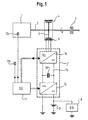
- the drive system according to Fig. 1 is e.g. for a motor vehicle, determined about a passenger car. It has a direct injection diesel engine with a small cubic capacity (e.g. 1500cm) 1 on, the torque via a drive shaft 2, a clutch 3 and other (not shown) parts of a drive train delivers the drive wheels of the vehicle.
- the diesel engine 1 is with no glow device and no preheating device equipped for the intake air. He also has no institution for heating the cooling water with the engine stopped.
- On the Drive shaft 2 is an electrical one serving as a starter / generator Machine 4, here an asynchronous three-phase machine, arranged. It has a seated directly on the drive shaft 2 and rotatably connected runner 5 and one e.g.
- the (not shown) winding of the stator 6 is by a Inverter 7 with electrical currents and voltages fed practically freely adjustable amplitude, phase and frequency. It is a DC link inverter, which is essentially one constant DC link voltage with the help of electronic Switches e.g. sine-weighted, wide-modulated pulses cuts out the - averaged by the inductance of the electrical machine 4 - to almost sinusoidal currents desired frequency, amplitude and phase.
- the inverter is essentially made up of a machine DC-AC converter 7a, one DC voltage intermediate circuit 7b and an electrical system side DC converter 7c constructed.
- the latter is with one Vehicle electrical system 8 and an electrical system long-term storage 9, here a conventional lead-sulfuric acid battery.
- the Vehicle electrical system 8 and the vehicle electrical system battery 9 are at a low level Voltage level, e.g. 12 or 24 volts.
- the intermediate circuit 7b on the other hand is due to an increased voltage, which is advantageous is in the range between 200 and 400 volts. With others Embodiments, the increased voltage is at the top of the low voltage range, around 36 volts.
- the intermediate circuit 7b is a short-term storage, here a capacitor storage 10 switched, which also the voltage in the intermediate circuit with a steep slope increasing current draw - the when pulses are generated by the converter 7a - approximately keeps constant.
- a short-term battery i.e. a quick-discharge battery
- the electrical machine 4 and the inverter 7 are like this designed to have the required torque and the necessary Power for directly driving the drive shaft 2 (e.g. the Crankshaft) of the diesel engine 1 to the required high Apply speed.
- the electrical machine 4 can, for example, after the starting process act as a generator, i.e. electrical power deliver.
- the converter 7c is a bidirectional converter educated. On the one hand, it can if the electrical machine 4 is operated as a motor and from the on-board electrical system battery 9 is fed, electrical energy from the electrical system battery 9 bring in the intermediate circuit 7b, and on the other hand if they as Generator is operated, energy from the intermediate circuit 7b for the purpose of feeding the consumers of the vehicle electrical system 8 and the vehicle electrical system battery 9 convict.
- the capacitor store 10 can also be used as an energy store for all or part of that required for starter operation Serve energy.
- the charging of the capacitor store 10 can be done in different ways: There is one possibility therein, the capacitor storage 10 even when the To keep diesel engine 1 charged: When operating the Diesel engine 1, i.e. in generator operation of the electrical machine 4 it will be charged anyway. When the engine stops the unavoidable slight charge losses are continuously recharged from the on-board electrical system battery 9. The start can then be done without waiting. Another one Reloading is not possible.
- the capacitor store 10 then discharges when the engine is at a standstill, and only from the on-board electrical system battery 9 before starting charged. In both cases, the whole does not need to Start required energy stored in the capacitor store 10 his.
- Embodiments takes a separate, with the Intermediate circuit 7b coupled energy store (e.g. a capacitor store or a short-term battery) storing the all or part of the starting energy. If at deep Temperatures a thermal starting aid for use comes, it is also advantageously from the capacitor store 10 fed. In embodiments (not shown) the supply of the starter 4 and possibly the thermal Starting aids wholly or partly from a battery, e.g. the on-board electrical system battery 9.
- the Intermediate circuit 7b coupled energy store e.g. a capacitor store or a short-term battery
- a higher-level control unit 11 controls the starting process by it the inverter 7, namely the converter 7a and the Converter 7c controls. It gives the converter 7a amplitude, phase and frequency of the three-phase voltage to be generated. the There is converter 7c the amount of current, the current direction for motor Operation and, if applicable, the amount of voltage increase (if energy is taken from the on-board electrical system battery 9).
- the control unit 11 controls the electrical Machine 4 via the inverter 7 such that the Drive shaft 2 to a high enough to ignite the fuel Speed is driven, not by one thermal booster system is made use of.
- the speed at which the diesel engine 1 from the electrical Machine 4 is driven (at least in a partial area) selected depending on temperature.
- an engine temperature sensor 12a and an outside temperature sensor 12 b provided to record the engine and outside temperature.
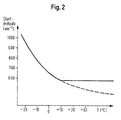
- Fig. 2 illustrates the dependence of the starting speed (ie the speed required for self-ignition, at which fuel is injected) on the temperature.
- the engine and outside temperature are assumed to be the same; Different values of these temperatures are taken into account by a corresponding map.
- the dependency drawn is such that the starting speed drops from a maximum (eg 400 min -1 ) at the lowest temperature with increasing temperature. Above a certain temperature (here 10 ° C) it is kept constant, ie it is in this area by an amount increasing with increasing temperature above the minimum required speed value. This setting of a minimum speed serves for starting comfort.
- a further temperature-dependent parameter can be the starting time, ie the time with which the diesel engine 1 is driven at the starting speed until fuel is injected.
- the start time is longer at low temperatures than at high ones, ie their temperature dependence is similar to the relationship shown in FIG. 2.
- these temperature dependencies are taken into account by variably setting the charge level at least so high that a safe start is ensured at the respective temperature.
- the control unit 11 provides for a permanent recharging or one-time charging from the on-board electrical system battery to the above-mentioned minimum charge level before the actual starting process.
- a battery as an energy source, its capacity and power are selected sufficiently to ensure starting with the required starter speed at all temperatures.
- the first step in step S1 is to ask whether a command to start the diesel engine 1 is given has been.
- process steps include one Measurement of temperatures, a determination of the safe Start at the required charge level measured temperature values e.g. with the help of a stored in the control unit 11 Map similar to Fig. 2, and a recharge of the capacitor store 10 to the required level.
- This episode of Process steps are ongoing during engine shutdown repeated. When operating with a single charge this sequence executed once after the start command.
- Step S2 measures the temperatures (if this did not happen immediately before) and one Determination of the safe start at the measured temperature values required starting speed and duration, e.g. With With the help of a map stored in the control unit 11. Without Then use thermal starting aids (step S3) in step S4 the crankshaft 2 of the diesel engine 1 from the electric starter 4 with the predetermined starting speed driven. After the predetermined start time has elapsed The injection of fuel begins in step S5. In the following Step S6 starts the diesel engine by auto-ignition, without a thermal jump starter would have been used, even at the deepest occurring operating temperatures.
Abstract
Description
Die vorliegende Erfindung betrifft ein Verfahren zum Starten eines Dieselmotors sowie ein Antriebssystem eines Kraftfahrzeugs mit einem Dieselmotor.The present invention relates to a method for starting of a diesel engine and a drive system of a motor vehicle with a diesel engine.
Die Startwilligkeit von Dieselmotoren nimmt zu niedrigen Temperaturen hin ab. Hierfür ist einerseits eine Erhöhung des Reibmomentes verantwortlich. Andererseits senken Leck- und Wärmeverluste beim Verdichten der Luft den Kompressionsenddruck sowie die Kompressionsendtemperatur ab. Herkömmlicherweise sind Dieselmotoren daher mit thermisch wirkenden Starthilfsmitteln ausgerüstet. Die Temperaturgrenze, ab der die Starthilfamittel eingesetzt werden müssen, hängt dabei i.a. von der Motorbauart ab. So haben direkt einspritzende Dieselmotoren mit einteiligem Brennraum (im folgenden "DI-Motoren" genannt) aufgrund geringerer Wärmeverluste ein besseres Startverhalten als Vor- und Wirbelkammer-Motoren, welche einen geteilten Brennraum aufweisen.The willingness of diesel engines to start takes off at low temperatures down. On the one hand, there is an increase in the frictional torque responsible. On the other hand, leakage and heat losses decrease when compressing the air the final compression pressure as well the final compression temperature. Traditionally Diesel engines therefore with thermal starting aids equipped. The temperature limit above which the jump starter must be used depends on of the engine type from. So have direct-injection diesel engines with one-piece Combustion chamber (hereinafter referred to as "DI engines") due to smaller Heat loss better starting behavior than pre-and swirl chamber engines, which have a divided combustion chamber.
Als Starthilfsmittel werden üblicherweise bei kleinvolumigen DI-Motoren sowie Motoren mit geteiltem Brennraum Glühstiftkerzen verwendet. Der Glühstift der Kerze ragt in den Brennraum bzw. in die Kammer des Motors. Neben Glühstiftkerzen sind auch Glühkerzen (im engeren Sinn) üblich, d.h. Glühkerzen mit freiliegendem Glühdraht. Bei großvolumigen Dieselmotoren beruht die thermische Starthilfe häufig auf einer Vorwärmung der angesaugten Luft mit Hilfe von elektrisch beheizbaren Anheizkerzen oder Heizflanschen (siehe Kraftfahrtechnisches Taschenbuch, 22. Aufl. 1995, VDI-Verlag, Düsseldorf, S. 538-540).Start-up aids are usually used in small-volume vehicles DI engines as well as engines with split combustion chamber glow plugs used. The glow plug of the candle protrudes into the combustion chamber or in the chamber of the engine. Besides glow plugs are also Glow plugs (in the narrower sense) common, i.e. Glow plugs with exposed Filament. In the case of large-volume diesel engines, the thermal jump start often on preheating the suction Air with the help of electrically heated spark plugs or Heating flanges (see Automotive Engineering Handbook, 22. Ed. 1995, VDI-Verlag, Düsseldorf, pp. 538-540).
Aus der JP 55-75568 ist eine Startervorrichtung für Dieselmotoren bekannt, bei der beim Startvorgang bei tiefen Temperaturen zunächst keine Luft in den Brennraum eingelassen wird, wodurch sich die Arbeitslast des Starters verringert und hierdurch die Anwerfdrehzahl erhöht. Zum Vorheizen der dann schließlich zum Starten eingelassenen Luft sind Glühkerzen vorgesehen. JP 55-75568 describes a starter device for diesel engines known, when starting at low temperatures initially no air is let into the combustion chamber, which means the starter's workload is reduced and as a result the Starting speed increased. To preheat it then to Glow plugs are provided to start let-in air.
Aus der DE 195 32 135 A1 ist ferner ein Antriebssystem mit einer Start-Stop-Automatik bekannt, bei dem in einer vorteilhaften Ausgestaltung ein elektrischer Starter einen Verbrennungsmotor bis zum Erreichen der Leerlaufdrehzahl antreibt. Dies dient dazu, den Verbrennungsmotor nach einem Stop mit Hilfe des elektrischen Starters direkt auf Leerlaufdrehzahl zu bringen.From DE 195 32 135 A1 a drive system with a Automatic start-stop is known, in an advantageous manner Embodiment an electric starter an internal combustion engine drives until idling speed is reached. This is used to stop the internal combustion engine after a stop electric starter directly to idle speed.
Aus der DE 28 53 130 A1 ist ein Schwungradstarter bekannt, der vor dem Startvorgang mit Hilfe eines elektrischen Antriebs auf eine so hohe Drehzahl gebracht wird, daß die gespeicherte kinetische Energie zum Starten ausreicht. Bei niedrigen Temperaturen wird eine größere Startenergie als bei hohen benötigt, entsprechend wird das Schwungrad zu tieferen Temperaturen auf höhere Drehzahl gebracht. Der Aspekt einer thermischen Starthilfe ist in dieser Druckschrift, in der es in erster Linie um eine spezielle Art des Schwungradantriebs geht, nicht erwähnt.A flywheel starter is known from DE 28 53 130 A1, the before starting with the help of an electric drive is brought to such a high speed that the stored kinetic energy is sufficient to start. at low temperatures will have a greater starting energy than at high, the flywheel is correspondingly lower Temperatures brought to higher speed. The aspect of a thermal jump start is in this document in which it primarily a special type of flywheel drive goes, not mentioned.
Die Firmenveröffentlichung: BOSCH Technische Unterrichtung, Elektrische Startanlagen, 1. Ausgabe, 1. Februar 1994, S. 5 und 11 gibt allgemeine Ausführungen zum Startvorgang sowie Angaben zur unteren Grenztemperatur verschiedener Startertypen.The company publication: BOSCH Technical Instruction, Electric starting systems, 1st edition, February 1, 1994, p. 5 and 11 gives general explanations of the starting process as well Information about the lower limit temperature of different starter types.
Aufgabe der vorliegenden Erfindung ist, ein verbessertes Verfahren zum Starten eines Dieselmotors anzugeben sowie ein entsprechendes Antriebssystem bereitzustellen.The object of the present invention is an improved method to specify a diesel engine to start and a corresponding To provide drive system.
Verfahrensmäßig wird diese Aufgabe gemäß Anspruch 1 durch ein Verfahren zum Starten eines Dieselmotors eines Kraftfahrzeugs, der kein thermisches Starthilfsmittel aufweist, mit folgenden Schritten, gelöst:
- die Motortemperatur wird erfaßt;
- in Abhängigkeit von der erfaßten Temperatur wird eine Drehzahl bestimmt, auf die der Dieselmotor zum Starten durch einen elektrischen Direktstarter ohne Verwendung eines thermischen Starthilfsmittels zu bringen ist, wobei diese Drehzahl bei niedriger Temperatur höher als bei hoher liegt;
- der Dieselmotor wird durch den elektrischen Starter direkt auf die bestimmte Drehzahl gebracht und dadurch gestartet.
- the engine temperature is recorded;
- depending on the temperature detected, a speed is determined to which the diesel engine is to be brought to start by a direct electric starter without using a thermal starting aid, this speed being higher at low temperature than at high;
- the electric starter brings the diesel engine to the specified speed and starts it.
Vorrichtungsmäßig wird diese Aufgabe gemäß Anspruch 7 durch ein Antriebssystem eines Kraftfahrzeugs gelöst, mit
- einem Dieselmotor, der kein thermisches Starthilfsmittel aufweist,
- einem elektrischen Direktstarter,
- Mitteln zum Erfassen der Motortemperatur und/oder der Außentemperatur, und
- einer Steuerung, die den Starter veranlaßt, den Dieselmotor auf eine, in Abhängigkeit von der erfaßten Temperatur variierte Drehzahl zu bringen, die zum Zünden des Kraftstoffs ausreicht, wobei die Drehzahl bei tiefen Temperaturen höher als bei tiefen Temperaturen liegt.
- a diesel engine that does not have a thermal starting aid,
- an electric direct starter,
- Means for detecting the engine temperature and / or the outside temperature, and
- a controller which causes the starter to bring the diesel engine to a speed which varies depending on the temperature sensed and which is sufficient to ignite the fuel, the speed being higher at low temperatures than at low temperatures.
Es wurde erkannt, daß ein wesentlicher Teil der Startprobleme bei niedrigen Temperaturen von der Abkühlung der durch die Kompression erwärmten Luft an den kalten Zylinderwänden herrührt. Aufbauend hierauf liegt der Erfindung der Gedanke zugrunde, daß durch eine Verkürzung der Kontaktzeit zwischen Luft und Zylinderwänden eine wesentliche Verbesserung des Selbstzünderstartverhaltens erzielt werden kann. Die kürzere Kontaktzeit wiederum wird durch eine schnellere Startdrehzahl erxielt. Beispielsweise beträgt bei einer Verdreifachung der Startdrehzahl gegenüber der herkömmlichen Startweise die Kontaktzeit im Zylinder ein Drittel des herkömmlichen Werts. Gemäß der Erfindung erfolgt also die Kompression beim Starten stärker im adiabatischen Bereich, so daß die für die Selbstzündung des Kraftstoffes erforderliche Grenztemperatur auch bei tiefen Temperaturen allein durch die Kompression erreicht wird. Die Verwendung von thermischen Starthilfseinrichtungen, wie Glühstiftkerzen oder Luftvorheizeinrichtungen im Ansaugtrakt kann dadurch ganz oder zumindest oberhalb einer tiefliegenden Grenztemperatur entfallen. Vorrichtungsmäßig weist der Dieselmotor daher kein thermisches Starthilfsmittel auf oder er ist so gesteuert, daß ein ggf. vorhandenes Starthilfsmittel nicht oder nur oberhalb der tiefliegenden Grenztemperatur zur Anwendung kommt. Vorzugsweise wird auch auf jegliche sonstige indirekte Vorheizung des Motors, z. B. in Form einer Kühlwasseranwärmung (ggf. oberhalb der tiefliegenden Grenztemperatur) verzichtet. Der Dieselmotor weist daher vorzugsweise auch keine derartige Einrichtung zum indirekten Vorheizen auf bzw. ist so gesteuert, daß eine solche Einrichtung zum Starten nicht oder nur oberhalb der tiefliegenden Grenztemperatur zur Anwendung kommt. Bei manchen Motorkonstruktionen kann eine Nachheizeinrichtung (z.B. eine Nachglühvorrichtung) vorgesehen sein, die in der ersten Zeit nach dem Start des Dieselmotors betrieben wird, um in der Aufwärmphase eine bessere Verbrennung herbeizuführen. Ein solches Heizen nach dem Start ist nicht als "Verwenden eines thermischen Starthilfsmittels" zu verstehen. Entsprechend wird auch ein Antriebssystem mit Glühkerzen o.ä., das so gesteuert ist, daß die Glühkerzen nur nach dem Start beheizt werden, nicht als "thermische Starthilfsmittel aufweisend" verstanden. Besonders vorteilhaft wird keine derartige Nachheizung durchgeführt und ist auch keine Nachheizeinrichtung vorhanden.It has been recognized that a significant part of the launch problems at low temperatures from cooling by compression heated air on the cold cylinder walls. Building on this, the invention is based on the idea that by reducing the contact time between air and cylinder walls a significant improvement in the misfire start behavior can be achieved. The shorter contact time in turn is achieved by a faster starting speed. For example is tripled compared to the starting speed the conventional starting method the contact time in the cylinder a third of the traditional value. According to the invention so the compression when starting more adiabatic Area so that for the auto-ignition of the fuel required limit temperature even at low temperatures is achieved solely by compression. The use of thermal jump starters, such as glow plugs or Air preheating devices in the intake tract can be completely or at least above a low limit temperature. In terms of the device, the diesel engine therefore has no thermal Jump starter on or it is controlled so that a any starting aid, if any, or only above the low limit temperature is used. Preferably is also used for any other indirect preheating of the engine, z. B. in the form of cooling water heating (possibly above the low limit temperature). The diesel engine therefore preferably has no such device for indirect preheating or is controlled so that such Device for starting not or only above the deep one Limit temperature is used. With some engine designs a post-heating device (e.g. an after-glow device) be provided in the first period after Start of the diesel engine is operated to warm up to bring about better combustion. Such heating after starting is not considered "using a thermal Starting aids "to understand. Accordingly, a drive system with glow plugs or the like, which is controlled so that the Glow plugs are heated only after starting, not as "Having thermal starting aids" understood. Especially no such post-heating is advantageously carried out and there is also no post-heating device.
Das erfindungsgemäße Verfahren bzw. Antriebssystem hat folgende Vorteile:
- die herkömmlicherweise für das Vorglühen oder Luftvorwärmen erforderliche Wartezeit entfällt (zumindest oberhalb der tiefliegenden Grenztemperatur), wodurch das Starten schneller erfolgen kann. Dies dient der Verkehrssicherheit (in Gefahrensituation, in der bei abgestelltem Motor ein schnelles Losfahren erforderlich ist) und erhöht den Komfort bei Dieselfahrzeugen;
- mit der Einsparung der herkömmlich vorhandenen thermischen Starthilfsanlage geht eine beträchtliche Aufwandsersparnis einher;
- die zum Starten benötigte Energiemenge ist geringer, was eine kleinere Dimensionierung der Starterbatterie erlaubt.
- the waiting time conventionally required for preheating or air preheating is eliminated (at least above the low limit temperature), which means that starting can take place more quickly. This serves traffic safety (in a dangerous situation, in which a fast start is necessary when the engine is switched off) and increases the comfort of diesel vehicles;
- the saving of the conventional thermal starting aid system is associated with a considerable saving of effort;
- the amount of energy required to start is less, which allows the starter battery to be dimensioned smaller.
Insgesamt leistet die vorliegende Erfindung damit einen Beitrag zur Verkehrssicherheit, zum Umweltschutz und zur Erhöhung des Fahrkomforts und zur Aufwandsverringerung bei Dieselfahrzeugen. Sie kann damit zur weiteren Verbreitung von Dieselfahrzeugen beitragen.Overall, the present invention thus makes a contribution on traffic safety, environmental protection and increasing the Driving comfort and to reduce effort in diesel vehicles. It can thus be used for the further spread of diesel vehicles contribute.
In den Unteransprüchen sind nähere Erläuterungen und vorteilhafte Ausgestaltungen angegeben:In the subclaims are more detailed explanations and advantageous Refinements specified:
Gemäß den Ansprüchen 2 bis 4 wird näher definiert, was vorteilhaft
unter "höher liegender Drehzahl" im Bereich tiefer Temperaturen
zu verstehen ist und zwar eine Drehzahl von 400 min-1
oder mehr, bevorzugt 600 min-1 oder mehr, weiter bevorzugt 800
min-1 oder mehr. Die maximale Drehzahl bei der tiefsten Temperatur
wird dabei typischerweise nicht über 1500 min-1 liegen.According to
Ansprüche 5 und 8 betreffen den Zeitpunkt, ab dem im Verlauf
des Startvorgangs Kraftstoff eingespritzt wird. Und zwar erfolgt
dies vorteilhaft erst nach Erreichen der Drehzahl, die
für das Selbstzünden des Kraftstoffs nötig ist. Dies spart
Kraftstoff und mindert die Rauchentwicklung.
Gemäß den Ansprüchen 6 und 9 handelt es sich bei dem Dieselmotor vorzugsweise um einen kleinvolumigen Motor mit weniger als 3000 cm3 Hubraum, besonders vorzugsweise weniger als 2000 cm3 Hubraum. Diese Art von Motoren wird insbesondere in Personenkraftwagen und Kleinnutzfahrzeugen mit einem Gesamtgewicht von weniger als 3,5 t eingesetzt. Bei solchen Motoren ist die Kühlung an dem Brennraum besonders stark ausgeprägt, und der von der Erfindung geleistete Verzicht auf thermische Starthilfsmittel ist daher hier besonders vorteilhaft.According to claims 6 and 9, the diesel engine is preferably a small-volume engine with a displacement of less than 3000 cm 3 , particularly preferably less than 2000 cm 3 . This type of engine is used in particular in passenger cars and small commercial vehicles with a total weight of less than 3.5 t. In such engines, the cooling in the combustion chamber is particularly pronounced, and the omission of thermal starting aids achieved by the invention is therefore particularly advantageous here.
Der Starter des Antriebssystems ist ein Direktstarter, d.h. er bringt die zum Starten erforderliche Leistung instantan (d.h. ohne Speicherung) durch Umwandlung elektrischer Energie in mechanische Energie auf. Es handelt sich also nicht um einen Schwungradstarter, dessen Antrieb nicht das zum Starten erforderliche Drehmoment aufbringen kann, so daß dem Antrieb das Starten nur indirekt aufgrund der Speicherung kinetischer Energie möglich ist.The starter of the drive system is a direct starter, i.e. he brings the power required to start instantaneously (i.e. without storage) by converting electrical energy into mechanical Energy on. So it's not one Flywheel starter, the drive of which is not what is required to start Can apply torque, so that the drive Start only indirectly due to the storage of kinetic energy is possible.
Gemäß Anspruch 10 handelt es sich bei dem Starter um eine als
Starter/Generator fungierende elektrische Maschine, die permanent
mitläuft, anders als ein Schwungradstarter vor dem Starten
aber nicht antreibend wirkt. Die Relativdrehzahl von elektrischer
Maschine zu Dieselmotor ist im Starter- und im Generatorbetrieb
gleich, d.h. das Übersetzungsverhältnis zwischen elektrischer
Maschine und Verbrennungsmotor ist konstant. Solche
Maschinen sind für Generatorbetrieb für hohe Drehzahlen ausgelegt.
Für den Starterbetrieb müssen sie imstande sein, hohe
Drehmomente aufzubringen. Dabei sind sie zur Erreichung der erforderlichen
hohen Startdrehzahl hervorragend geeignet. Gemäß
Anspruch 11 handelt es sich bei dem elektrischen Starter um eine
wechselrichtergesteuerte Drehfeldmaschine. Unter
"Drehfeldmaschine" wird eine Maschine verstanden, in der ein
magnetisches Drehfeld auftritt, das um 360° umläuft und dabei
den Läufer mitnimmt. Der Wechselrichter stellt für die Erzeugung
des Drehfelds Wechsel- oder Drehstrom mit frei einstellbarer
Frequenz, Amplitude und Phase bereit. Gemäß Anspruch 12
wird die zum Starten erforderliche Energie zumindest teilweise
einem Kondensatorspeicher (z.B. einem sogenannten Zwischenkreisspeicher)
entnommen, dessen Vorladung gemäß Anspruch 13
temperaturabhängig erfolgen kann. Gemäß Anspruch 14 wird die
Energie zum Starten zumindest teilweise einer Batterie entnommen.According to
Ausgestaltungen und Merkmale, die vorausgehend oder nachfolgende im Zusammenhang mit dem Verfahren geschildert werden, gelten selbstverständlich auch als im Zusammenhang mit dem Antriebssystem offenbart (und umgekehrt). Refinements and features preceding or following described in connection with the procedure apply of course also in connection with the drive system revealed (and vice versa).
Die Erfindung wird nun anhand von Ausführungsbeispielen und den angefügten schematischen Zeichnungen näher erläutert. In der Zeichnung zeigen:
- Fig. 1
- eine schematische Darstellung eines Anstriebssystems mit einem Dieselmotor;
- Fig. 2
- eine Veranschaulichung des Zusammenhangs zwischen Startdrehzahl und Temperatur;
- Fig. 3
- ein Flußdiagramm zum Starten des Dieselmotors im kalten Zustand bei tiefer Temperatur.
- Fig. 1
- a schematic representation of a drive system with a diesel engine;
- Fig. 2
- an illustration of the relationship between starting speed and temperature;
- Fig. 3
- a flow chart for starting the diesel engine in the cold state at low temperature.
Das Antriebssystem gemäß Fig. 1 ist z.B. für ein Kraftfahrzeug,
etwa einen Personenkraftwagen bestimmt. Es weist einen Direkteinspritzer-Dieselmotor
mit kleinem Hubraum (z.B. 1500cm ) 1
auf, der Drehmoment über eine Antriebswelle 2, eine Kupplung 3
und weitere (nicht gezeigte) Teile eines Antriebsstranges auf
die Antriebsräder des Fahrzeugs abgibt. Der Dieselmotor 1 ist
mit keiner Glüheinrichtung und auch keiner Vorwärmeinrichtung
für die Ansaugluft ausgerüstet. Er weist auch keine Einrichtung
zum Beheizen des Kühlwassers bei stehendem Motor auf. Auf der
Antriebswelle 2 ist eine als Starter/Generator dienende elektrische
Maschine 4, hier eine Asynchron-Drehstrommaschine, angeordnet.
Sie weist einen direkt auf der Antriebswelle 2 sitzenden
und drehfest mit ihr verbundenen Läufer 5 sowie einen
z.B. am Gehäuse des Dieselmotors 1 abgestützten Ständer 6 auf.
Die (nicht dargestellte) Wicklung des Ständers 6 wird durch einen
Wechselrichter 7 mit elektrischen Strömen und Spannungen
praktisch frei einstellbarer Amplitude, Phase und Frequenz gespeist.
Es handelt es sich um einen Gleichspannungs-Zwischenkreis-Wechselrichter,
welcher aus einer im wesentlichen
konstanten Zwischenkreis-Gleichspannung mit Hilfe von elektronischen
Schaltern z.B. sinusbewertete breitenmodulierte Pulse
herausschneidet, die - gemittelt durch die Induktivität der
elektrischen Maschine 4 - zu nahezu sinusförmigen Strömen der
gewünschten Frequenz, Amplitude und Phase führen.The drive system according to Fig. 1 is e.g. for a motor vehicle,
determined about a passenger car. It has a direct injection diesel engine
with a small cubic capacity (e.g. 1500cm) 1
on, the torque via a
Der Wechselrichter ist im wesentlichen aus einem maschinenseitigen
Gleichspannungs-Wechselspannungsumrichter 7a, einem
Gleichspannungs-Zwischenkreis 7b und einem bordnetzseitigen
Gleichspannungswandler 7c aufgebaut. Letzterer ist mit einem
Fahrzeugbordnetz 8 und einem Bordnetz-Langzeitspeicher 9, hier
einer herkömmlichen Blei-Schwefelsäure-Batterie, gekoppelt. Das
Bordnetz 8 und die Bordnetzbatterie 9 liegen auf einem niedrigen
Spannungsniveau, z.B. 12 oder 24 Volt. Der Zwischenkreis 7b
liegt demgegenüber auf einer erhöhten Spannung, die vorteilhafterweise
im Bereich zwischen 200 und 400 Volt liegt. Bei anderen
Ausführungsformen liegt die erhöhte Spannung am oberen Rand
des Niederspannungsbereichs, etwa bei 36 Volt. In den Zwischenkreis
7b ist ein Kurzzeitspeicher, hier ein Kondensatorspeicher
10 geschaltet, welcher die Spannung im Zwischenkreis auch bei
mit großer Flankensteilheit ansteigender Stromentnahme - die
bei Erzeugung von Pulsen durch den Umrichter 7a vorliegt - annähernd
konstant hält. Bei anderen (nicht gezeigten) Ausführungsformen
wird der Kurzzeitspeicher durch eine Kurzzeitbatterie
(d.h. eine schnell entladbare Batterie) gebildet.The inverter is essentially made up of a machine
DC-
Die elektrische Maschine 4 und der Wechselrichter 7 sind so
ausgelegt, daß sie das erforderliche Drehmoment und die nötige
Leistung zum direkten Antreiben der Antriebswelle 2 (z.B. der
Kurbelwelle) des Dieselmotors 1 auf die erforderliche hohe
Drehzahl aufbringen.The electrical machine 4 and the
Die elektrische Maschine 4 kann nach dem Startvorgang beispielsweise
als Generator fungieren, d.h. elektrische Energie
liefern. Der Wandler 7c ist hierfür als bidirektionaler Wandler
ausgebildet. Er kann einerseits, wenn die elektrische Maschine
4 als Motor betrieben wird und dabei aus der Bordnetzbatterie 9
gespeist wird, elektrische Energie aus der Bordnetzbatterie 9
in den Zwischenkreis 7b bringen, und andererseits, wenn sie als
Generator betrieben wird, Energie aus dem Zwischenkreis 7b
zwecks Speisung der Verbraucher des Bordnetzes 8 und der Bordnetzbatterie
9 überführen.The electrical machine 4 can, for example, after the starting process
act as a generator, i.e. electrical power
deliver. For this purpose, the
Der Kondensatorspeicher 10 kann auch als Energiespeicher für
die gesamte oder einen Teil der für den Starterbetrieb benötigten
Energie dienen. Die Aufladung des Kondensatorspeichers 10
kann auf unterschiedliche Weisen erfolgen: Eine Möglichkeit besteht
darin, den Kondensatorspeicher 10 auch bei abgestelltem
Dieselmotor 1 im geladenen Zustand zu halten: Bei Betrieb des
Dieselmotors 1, d.h. im Generatorbetrieb der elektrischen Maschine
4 wird er ohnehin aufgeladen. Bei anschließendem Motorstillstand
werden laufend die unvermeidlichen geringfügigen Ladungsverluste
aus der Bordnetzbatterie 9 nachgeladen. Das Starten
kann dann ohne jede Wartezeit erfolgen. Bei einer anderen
Möglichkeit wird auf das Nachladen verzichtet. Der Kondensatorspeicher
10 entlädt sich dann bei längerem Motorstillstand, und
wird erst jeweils vor dem Starten aus der Bordnetzbatterie 9
aufgeladen. Bei beiden Fällen braucht nicht die gesamte zum
Starten erforderliche Energie im Kondensatorspeicher 10 gespeichert
sein. Ein Teil davon kann auch während des Startvorgangs
der Bordnetzbatterie 9 entnommen werden. Bei anderen (nicht gezeigten)
Ausführungsformen übernimmt ein gesonderter, mit dem
Zwischenkreis 7b gekoppelter Energiespeicher (z.B. ein Kondensatorspeicher
oder eine Kurzzeitbatterie) die Speicherung der
gesamten oder eines Teils der Startenergie. Falls bei tiefen
Temperaturen ein thermisches Starthilfsmittel zur Anwendung
kommt, wird es vorteilhafterweise auch aus dem Kondensatorspeicher
10 gespeist. Bei (nicht gezeigten) Ausführungsformen erfolgt
die Speisung des Starters 4 und ggf. der thermischen
Starthilfsmittel ganz oder teilweise aus einer Batterie, z.B.
der Bordnetzbatterie 9.The
Ein übergeordnetes Steuergerät 11 steuert den Startvorgang, indem
es den Wechselrichter 7, und zwar den Umrichter 7a und den
Wandler 7c steuert. Es gibt dem Umrichter 7a Amplitude, Phase
und Frequenz der zu erzeugenden Dreiphasenspannung vor. Dem
Wandler 7c gibt es den Strombetrag, die Stromrichtung für motorischen
Betrieb und ggf. den Betrag der Spannungsheraufsetzung
(falls der Bordnetzbatterie 9 Energie entnommen wird) vor. Zum
Starten des Dieselmotors 1 steuert das Steuergerät 11 die elektrische
Maschine 4 über den Wechselrichter 7 derart, daß die
Antriebswelle 2 auf eine hohe, zum Zünden des Kraftstoffs ausreichende
Drehzahl angetrieben wird, wobei nicht von einer
thermischen Starthilfsanlage Gebrauch gemacht wird.A higher-
Die Drehzahl, auf welche der Dieselmotor 1 von der elektrischen
Maschine 4 angetrieben wird (zumindest in einem Teilbereich)
temperaturabhängig gewählt. Zur Erfassung der Motor- und Außentemperatur
ist ein Motortemperatursensor 12a sowie ein Außentemperatursensor
12 b vorgesehen.The speed at which the
Fig. 2 veranschaulicht die Abhängigkeit der Startdrehzahl (d.h.
die zum Selbstzünden erforderliche Drehzahl, bei deren Erreichen
Kraftstoff eingespritzt wird) von der Temperatur. Zur Vereinfachung
sind hier Motor- und Außentemperatur als gleich angenommen;
unterschiedliche Werte dieser Temperaturen werden
durch ein entsprechendes Kennfeld berücksichtigt. Die gezeichnete
Abhängigkeit ist derart, daß die Startdrehzahl von einem
Maximum (z.B. 400 min-1) bei der tiefsten Temperatur mit steigender
Temperatur abfällt. Oberhalb einer gewissen Temperatur
(hier 10°C) wird sie konstant gehalten, befindet sich also in
diesem Bereich um einen mit steigender Temperatur zunehmenden
Betrag über dem jeweils mindestens erforderlichen Drehzahlwert.
Diese Einstellung einer Mindestdrehzahl dient dem Startkomfort.
Ein weiterer (hier nicht näher veranschaulichter) temperaturabhängiger
Parameter kann die Startdauer sein, d.h. die Dauer mit
der der Dieselmotor 1 bei der Startdrehzahl angetrieben wird,
bis Kraftstoff eingespritzt wird. Bei niedrigen Temperaturen
ist die Startdauer größer als bei hohen, d.h. ihre Temperaturabhängigkeit
ähnelt dem in Fig. 2 dargestellten Zusammenhang.
Bei der Aufladung des Kondensatorspeichers 10 werden diese Temperaturabhängigkeiten
berücksichtigt, indem der Ladungspegel in
variabler Weise mindestens so hoch gelegt wird, daß bei der jeweils
vorliegenden Temperatur ein sicheres Starten gewährleistet
ist. Je nachdem, ob der Kondensatorspeicher 10 dauernd
aufgeladen ist oder nur kurz vor dem Starten aufgeladen wird,
sorgt das Steuergerät 11 vor dem eigentlichen startvorgang für
eine dauernde Nachladung bzw. einmalige Aufladung aus der Bordnetzbatterie
auf den o.g. erforderlichen Mindestladepegel. Bei
Verwendung einer Batterie als Energiequelle wird deren Kapazität
und Leistung ausreichend gewählt, um ein Starten mit erforderlicher
Starterdrehzahl bei allen Temperaturen zu gewährleisten.Fig. 2 illustrates the dependence of the starting speed (ie the speed required for self-ignition, at which fuel is injected) on the temperature. To simplify matters, the engine and outside temperature are assumed to be the same; Different values of these temperatures are taken into account by a corresponding map. The dependency drawn is such that the starting speed drops from a maximum (eg 400 min -1 ) at the lowest temperature with increasing temperature. Above a certain temperature (here 10 ° C) it is kept constant, ie it is in this area by an amount increasing with increasing temperature above the minimum required speed value. This setting of a minimum speed serves for starting comfort. A further temperature-dependent parameter (not illustrated in more detail here) can be the starting time, ie the time with which the
Bei dem Verfahren gemäß Fig. 3 wird im Schritt S1 zunächst abgefragt,
ob ein Kommando zum Starten des Dieselmotors 1 gegeben
wurde. Bei der Betriebsweise mit kontinuierlicher Nachladung
ist durch vorausgehende (nicht gezeigte) Verfahrensschritte sichergestellt,
daß der Kondensatorspeicher 10 ausreichend geladen
ist, um den Dieselmotor 1 bei den vorliegenden Temperaturverhältnissen
ohne Verwendung von thermischen Starthilfsmitteln
sicher starten zu können. Diese Verfahrensschritte umfassen eine
Messung der Temperaturen, eine Bestimmung des zum sicheren
Starten bei gemessenen Teperaturwerten erforderlichen Aufladungspegels
z.B. mit Hilfe eines im Steuergerät 11 gespeicherten
Kennfelds ähnlich Fig. 2, und ein Nachladen des Kondensatorspeichers
10 auf den erforderlichen Pegel. Diese Folge von
Verfahrensschritten wird während des Motorstillstands laufend
wiederholt. Bei der Betriebsweise mit einmaliger Aufladung wird
diese Folge einmalig nach dem Startkommando ausgeführt. Im
Schritt S2 erfolgt dann eine Messung der Temperaturen (falls
dies nicht unmittelbar vorher bereits geschehen ist) und eine
Bestimmung der zum sicheren Starten bei den gemessenen Temperaturwerten
erforderlichen Startdrehzahl und Startdauer, z.B. mit
Hilfe eines im Steuergerät 11 gespeicherten Kennfelds. Ohne
Verwendung thermischer Starthilfsmittel (Schritt S3) wird dann
im Schritt S4 die Kurbelwelle 2 des Dieselmotors 1 von dem
elektrischen Starter 4 mit der vorher bestimmten Startdrehzahl
angetrieben. Nach Verstreichen der vorher bestimmten Startdauer
beginnt im Schritt S5 die Einspritzung des Kraftstoffs. Im darauffolgenden
Schritt S6 startet der Dieselmotor durch Selbstzündung,
ohne daß von einer thermischen Starthilfseinrichtung
Gebrauch gemacht worden wäre, und zwar auch bei den tiefsten
vorkommenden Gebrauchstemperaturen.In the method according to FIG. 3, the first step in step S1 is to ask
whether a command to start the
Claims (14)
- A method for starting a Diesel engine (1) of a motor vehicle, which has no thermal starting devices, having the following steps:the engine temperature is recorded;in dependence on the recorded temperature a speed is determined to which the Diesel engine (1) is to be brought for starting by an electric direct starter (4) without using a thermal starting device, with this speed being higher at low temperatures than at high temperatures;the Diesel engine (1) is directly brought to the determined speed by the electric starter (4) and is started thereby.
- A method according to Claim 1, in which the electric starter (4) drives the Diesel engine (1) in the low-temperature range to a speed of 400 min-1 or above.
- A method according to Claim 2, in which the electric starter (4) drives the Diesel engine (1) in the low-temperature range to a speed of 600 min-1 or above.
- A method according to Claim 3, in which the electric starter (4) drives the Diesel engine (1) in the low-temperature range to a speed of 800 min-1 or more.
- A method according to one of Claims 1 to 4, whereby the injection of the fuel into the combustion chamber of the Diesel engine (1) takes place only after a determined speed has been reached.
- A method according to one of Claims 1 to 5, whereby a Diesel engine (1) is used which has a small volume and is designed in particular for use in passenger vehicles and low-usage vehicles.
- A drive system of a motor vehicle, havinga Diesel engine (1) comprising no thermal starting devices,an electric direct starter (4),means (12a, 12b) for recording the engine temperature and/or the external temperature, anda control unit (11) which causes the starter (4) to bring the Diesel engine (1) to a speed which is varied in dependence on the recorded temperature which is sufficient to ignite the fuel, with the speed being higher at low temperatures than at low temperatures.
- A drive system according to Claim 7, whereby the injection of the fuel into the combustion chamber of the Diesel engine (1) take place only after the speed which is sufficient to ignite the fuel has been reached.
- A drive system according to Claim 7 or 8, in which the Diesel engine (1) has a small volume and is designed in particular for use in passenger vehicles and low-usage vehicles.
- A drive system according to one of Claims 7 to 9, in which the electric direct starter (4) is constructed as a starter/generator which permanently runs along with the Diesel engine (1).
- A drive system according to one of Claims 7 to 10, in which the electric direct starter (4) is a three-phase machine controlled by anverter.
- A drive system according to one of Claims 7 to 11, in which the energy required for starting is taken at least to some extent from a capacitor store (10).
- A drive system according to Claim 12, in which the preliminary charging of the capacitor store (10) takes place as a function of temperature.
- A drive system according to one of Claims 7 to 13, in which the energy required for starting is taken at least to some extent from a battery.
Applications Claiming Priority (3)
| Application Number | Priority Date | Filing Date | Title |
|---|---|---|---|
| DE19732630 | 1997-07-29 | ||
| DE19732630A DE19732630A1 (en) | 1997-07-29 | 1997-07-29 | Method for starting a diesel engine and drive system with a diesel engine |
| PCT/EP1998/004718 WO1999006693A1 (en) | 1997-07-29 | 1998-07-28 | Starting mode with a diesel engine and propulsion system with such an engine |
Publications (2)
| Publication Number | Publication Date |
|---|---|
| EP1000242A1 EP1000242A1 (en) | 2000-05-17 |
| EP1000242B1 true EP1000242B1 (en) | 2003-05-14 |
Family
ID=7837249
Family Applications (1)
| Application Number | Title | Priority Date | Filing Date |
|---|---|---|---|
| EP98945105A Expired - Lifetime EP1000242B1 (en) | 1997-07-29 | 1998-07-28 | Starting mode with a diesel engine and propulsion system with such an engine |
Country Status (3)
| Country | Link |
|---|---|
| EP (1) | EP1000242B1 (en) |
| DE (2) | DE19732630A1 (en) |
| WO (1) | WO1999006693A1 (en) |
Families Citing this family (4)
| Publication number | Priority date | Publication date | Assignee | Title |
|---|---|---|---|---|
| JP3649171B2 (en) * | 2001-08-22 | 2005-05-18 | トヨタ自動車株式会社 | Control device for internal combustion engine |
| DE10246978A1 (en) * | 2002-10-09 | 2004-04-22 | Daimlerchrysler Ag | Starting system for road vehicle with electrical machine and internal combustion engine has electronic circuit performing difficult start routine below given temperature and hot start above it |
| US7464681B2 (en) | 2006-02-28 | 2008-12-16 | Caterpillar Inc. | Engine and engine control method |
| CN104421089B (en) * | 2013-09-11 | 2016-08-10 | 上海汽车集团股份有限公司 | The engine starting system of hybrid vehicle and method |
Family Cites Families (5)
| Publication number | Priority date | Publication date | Assignee | Title |
|---|---|---|---|---|
| JPS5575568A (en) * | 1978-11-30 | 1980-06-06 | Nissan Motor Co Ltd | Diesel engine starter |
| DE2853130A1 (en) * | 1978-12-08 | 1980-06-19 | Luk Lamellen & Kupplungsbau | DEVICE FOR STARTING AN INTERNAL COMBUSTION ENGINE |
| SU1168741A1 (en) * | 1983-08-03 | 1985-07-23 | Организация П/Я А-3500 | Method of automatic programmed start of diesel engine |
| US4754730A (en) * | 1986-12-01 | 1988-07-05 | Marc Campagna | Motor vehicle starting system |
| DE19532135A1 (en) * | 1995-08-31 | 1997-03-06 | Clouth Gummiwerke Ag | Drive system, in particular for a motor vehicle, and method for operating the same |
-
1997
- 1997-07-29 DE DE19732630A patent/DE19732630A1/en not_active Withdrawn
-
1998
- 1998-07-28 EP EP98945105A patent/EP1000242B1/en not_active Expired - Lifetime
- 1998-07-28 WO PCT/EP1998/004718 patent/WO1999006693A1/en active IP Right Grant
- 1998-07-28 DE DE59808376T patent/DE59808376D1/en not_active Expired - Lifetime
Also Published As
| Publication number | Publication date |
|---|---|
| EP1000242A1 (en) | 2000-05-17 |
| DE59808376D1 (en) | 2003-06-18 |
| WO1999006693A1 (en) | 1999-02-11 |
| DE19732630A1 (en) | 1999-02-04 |
Similar Documents
| Publication | Publication Date | Title |
|---|---|---|
| EP0964995B1 (en) | Starter systems for an internal combustion engine and methods for starting an internal combustion engine | |
| EP1112447B1 (en) | Starter system for an internal combustion engine and method for starting an internal combustion engine | |
| EP1073842B2 (en) | Method and starter system for starting an internal combustion engine | |
| DE19704153C2 (en) | Drive system, in particular for a motor vehicle and method for counteracting a change in the idle speed in a drive system | |
| EP0847487B2 (en) | Drive system with a drive engine, an electrical machine and a battery | |
| EP1676738B1 (en) | Method and apparatus for control of hybrid energy storage in a hybrid vehicle | |
| EP0964996B1 (en) | Auxiliary starting device for a diesel engine and method for starting a diesel engine | |
| DE102004062939B4 (en) | Method and device for optimized starting of an internal combustion engine | |
| DE10301470A1 (en) | Control device and method for a device for storing energy in motorized vehicles | |
| WO2005012719A1 (en) | Control of an electrically heated pre-heating device for cold-starting internal combustion engines | |
| EP0577987A2 (en) | Device for controlling the output voltage of an engine-driven generator | |
| DE19809399C2 (en) | Starting system for a diesel engine | |
| EP1313628B1 (en) | Method for operating a drive with an internal combustion engine and an electric machine | |
| EP1000242B1 (en) | Starting mode with a diesel engine and propulsion system with such an engine | |
| DE4041630C2 (en) | ||
| DE19903082C2 (en) | Battery system and method for operating a battery system | |
| EP1128044A2 (en) | Vehicle drive system and method | |
| EP1144218A3 (en) | Drive unit for a motor vehicle | |
| DE102005052879A1 (en) | Self-igniting internal combustion engine operating method for motor vehicle, involves controlling heating device and starter motor depending on charging condition or operating parameter of battery that supplies energy to device and motor | |
| EP2596233A1 (en) | Method and device for controlling the ignition behaviour of a sheathed-type glow plug of a combustion engine | |
| DE102004023505B4 (en) | Method for energy management in an electrical system of a hybrid vehicle and an electrical system | |
| DE102009034765A1 (en) | Method for starting internal combustion engine of electric hybrid vehicle, involves injecting fuel into internal combustion engine, and igniting fuel with predetermined starting speed of internal combustion engine |
Legal Events
| Date | Code | Title | Description |
|---|---|---|---|
| PUAI | Public reference made under article 153(3) epc to a published international application that has entered the european phase |
Free format text: ORIGINAL CODE: 0009012 |
|
| 17P | Request for examination filed |
Effective date: 19991217 |
|
| AK | Designated contracting states |
Kind code of ref document: A1 Designated state(s): DE FR GB IT |
|
| RAP1 | Party data changed (applicant data changed or rights of an application transferred) |
Owner name: CONTINENTAL ISAD ELECTRONIC SYSTEMS GMBH & CO. OHG |
|
| 17Q | First examination report despatched |
Effective date: 20020214 |
|
| GRAH | Despatch of communication of intention to grant a patent |
Free format text: ORIGINAL CODE: EPIDOS IGRA |
|
| GRAH | Despatch of communication of intention to grant a patent |
Free format text: ORIGINAL CODE: EPIDOS IGRA |
|
| GRAA | (expected) grant |
Free format text: ORIGINAL CODE: 0009210 |
|
| AK | Designated contracting states |
Designated state(s): DE FR GB IT |
|
| REG | Reference to a national code |
Ref country code: GB Ref legal event code: FG4D Free format text: NOT ENGLISH |
|
| REF | Corresponds to: |
Ref document number: 59808376 Country of ref document: DE Date of ref document: 20030618 Kind code of ref document: P |
|
| GBT | Gb: translation of ep patent filed (gb section 77(6)(a)/1977) | ||
| ET | Fr: translation filed | ||
| PLBE | No opposition filed within time limit |
Free format text: ORIGINAL CODE: 0009261 |
|
| STAA | Information on the status of an ep patent application or granted ep patent |
Free format text: STATUS: NO OPPOSITION FILED WITHIN TIME LIMIT |
|
| 26N | No opposition filed |
Effective date: 20040217 |
|
| PGFP | Annual fee paid to national office [announced via postgrant information from national office to epo] |
Ref country code: GB Payment date: 20050725 Year of fee payment: 8 |
|
| PG25 | Lapsed in a contracting state [announced via postgrant information from national office to epo] |
Ref country code: GB Free format text: LAPSE BECAUSE OF NON-PAYMENT OF DUE FEES Effective date: 20060728 |
|
| PGFP | Annual fee paid to national office [announced via postgrant information from national office to epo] |
Ref country code: IT Payment date: 20060731 Year of fee payment: 9 |
|
| GBPC | Gb: european patent ceased through non-payment of renewal fee |
Effective date: 20060728 |
|
| REG | Reference to a national code |
Ref country code: FR Ref legal event code: TP |
|
| PG25 | Lapsed in a contracting state [announced via postgrant information from national office to epo] |
Ref country code: IT Free format text: LAPSE BECAUSE OF NON-PAYMENT OF DUE FEES Effective date: 20070728 |
|
| PGFP | Annual fee paid to national office [announced via postgrant information from national office to epo] |
Ref country code: FR Payment date: 20100805 Year of fee payment: 13 Ref country code: DE Payment date: 20100723 Year of fee payment: 13 |
|
| REG | Reference to a national code |
Ref country code: FR Ref legal event code: ST Effective date: 20120330 |
|
| PG25 | Lapsed in a contracting state [announced via postgrant information from national office to epo] |
Ref country code: FR Free format text: LAPSE BECAUSE OF NON-PAYMENT OF DUE FEES Effective date: 20110801 Ref country code: DE Free format text: LAPSE BECAUSE OF NON-PAYMENT OF DUE FEES Effective date: 20120201 |
|
| REG | Reference to a national code |
Ref country code: DE Ref legal event code: R119 Ref document number: 59808376 Country of ref document: DE Effective date: 20120201 |