EP0964980B1 - Axialkolbenmaschine mit drehzahlabhängiger anpressung der zylindertrommel - Google Patents
Axialkolbenmaschine mit drehzahlabhängiger anpressung der zylindertrommel Download PDFInfo
- Publication number
- EP0964980B1 EP0964980B1 EP98909381A EP98909381A EP0964980B1 EP 0964980 B1 EP0964980 B1 EP 0964980B1 EP 98909381 A EP98909381 A EP 98909381A EP 98909381 A EP98909381 A EP 98909381A EP 0964980 B1 EP0964980 B1 EP 0964980B1
- Authority
- EP
- European Patent Office
- Prior art keywords
- drive shaft
- cylinder drum
- force
- centrifugal
- piston machine
- Prior art date
- Legal status (The legal status is an assumption and is not a legal conclusion. Google has not performed a legal analysis and makes no representation as to the accuracy of the status listed.)
- Expired - Lifetime
Links
- 230000001419 dependent effect Effects 0.000 title description 8
- 244000208734 Pisonia aculeata Species 0.000 claims 5
- 238000010276 construction Methods 0.000 description 3
- 238000011161 development Methods 0.000 description 2
- 230000018109 developmental process Effects 0.000 description 2
- 238000010586 diagram Methods 0.000 description 2
- 230000000694 effects Effects 0.000 description 2
- 238000009434 installation Methods 0.000 description 2
- 230000036316 preload Effects 0.000 description 2
- 230000003252 repetitive effect Effects 0.000 description 2
- 238000007789 sealing Methods 0.000 description 2
- 230000005540 biological transmission Effects 0.000 description 1
- 238000005352 clarification Methods 0.000 description 1
- 230000000295 complement effect Effects 0.000 description 1
- 125000004122 cyclic group Chemical group 0.000 description 1
- 230000002706 hydrostatic effect Effects 0.000 description 1
- 238000004519 manufacturing process Methods 0.000 description 1
- 230000001404 mediated effect Effects 0.000 description 1
- 238000013508 migration Methods 0.000 description 1
- 230000005012 migration Effects 0.000 description 1
- 230000000149 penetrating effect Effects 0.000 description 1
Images


Classifications
-
- F—MECHANICAL ENGINEERING; LIGHTING; HEATING; WEAPONS; BLASTING
- F01—MACHINES OR ENGINES IN GENERAL; ENGINE PLANTS IN GENERAL; STEAM ENGINES
- F01B—MACHINES OR ENGINES, IN GENERAL OR OF POSITIVE-DISPLACEMENT TYPE, e.g. STEAM ENGINES
- F01B3/00—Reciprocating-piston machines or engines with cylinder axes coaxial with, or parallel or inclined to, main shaft axis
- F01B3/0032—Reciprocating-piston machines or engines with cylinder axes coaxial with, or parallel or inclined to, main shaft axis having rotary cylinder block
- F01B3/0041—Arrangements for pressing the cylinder barrel against the valve plate, e.g. fluid pressure
Definitions
- the invention relates to an axial piston machine according to the preamble of claim 1.
- An axial piston machine is e.g. from DE 195 22 168 A 1 known.
- the axial piston machine disclosed there consists of one in one Housing rotatably mounted about a drive shaft axis, one with the Drive shaft rotatably connected cylinder drum, in which cylinder for receiving axially movable pistons are formed, and a control plate with control openings for Cyclic connection of the cylinders with a high and a low pressure line.
- a pressing device is provided to the cylinder drum against the To press control plate and thus to bias against the control plate.
- the rotating cylinder drum is preloaded against the stationary control plate required to provide a sealing seal between the cylinder drum and the To ensure control plate and to lift the cylinder drum from the Counteract control plate at high speeds. In particular, one does not have to centric migration of the cylinder drum reliably prevented at high speeds become.
- the pressure device known from DE 195 22 168 A1 consists essentially of one provided in the cavity between the drive shaft and the cylinder drum Contact spring, which is at one end to the drive shaft and at the other end is supported on the cylinder drum and thus the cylinder drum opposite one Terminal block on which the drive shaft is mounted and in which the Control openings are provided, prestressed.
- the pressure spring By the pressure spring, however, one of independent, constant contact pressure exerted on the cylinder drum. This is disadvantageous in that the pressing force required by the piston Exerted inertia forces is given, which is with the square of The operating speed of the cylinder drum increases.
- the one exerted by the pressure spring Contact pressure must therefore be designed for the maximum speed of the cylinder drum and be sized accordingly.
- EP 0 162 238 B1 therefore proposes circumferentially on the cylinder drum to arrange distributed hydraulic auxiliary cylinders, their working spaces with the Cylinder bores of the master cylinder are connected. Using the auxiliary cylinder Working pressure and thus speed-dependent pressing of the cylinder drum achieved.
- a disadvantage of this solution is the relatively high outlay for training the additional hydraulic cylinders, which leads to relatively high manufacturing costs. Furthermore, the space required for the axial piston machine is increased.
- DE-OS 24 46 535 from which it is known by means of a centrifugal force device on the hold-down device for pressing the To act on the swashplate.
- a centrifugal force device on the hold-down device for pressing the To act on the swashplate.
- This centrifugal device is used however only for pressing the sliding shoes against the swashplate of the Axial piston machine, which requires comparatively much lower forces than for pressing the cylinder drum onto the control plate.
- the Centrifugal device has a relatively low efficiency, since that is the cylinder drum penetrating linkage is inclined in the radial direction and therefore only a relatively small axial force component is transmitted to the hold-down device.
- the Construction is relatively complex and expensive.
- the arrangement of the flyweights in Outside diameter also leads to an undesirable increase in the installation space Axial piston.
- the assembly play in the flyweights by the surrounding auxiliary or pressure elements are not balanced. Therefore, at relative low speeds and when accelerating from standstill the system of Flyweights on the support elements or pressure elements and thus an effect of Flying weights on the device are not guaranteed. The consequence is one insufficient contact pressure of the sliding shoes in the low speed range.
- the invention has for its object an axial piston machine with a Specify pressure device for pressing the cylinder drum to the control plate, at which avoids unnecessarily high contact pressure in the low speed range and which is structurally simple.
- the invention is based on the finding that a pressure device with a speed-dependent contact pressure for pressing the cylinder drum against the Control plate can be realized in a simple manner by using centrifugal bodies can, the centrifugal force in a on the cylinder drum attacking contact pressure with a directed towards the control plate and implement axial force component with respect to the drive shaft axis. This will make one unnecessarily high contact pressure in the low speed range avoided and the Minimized friction losses. Furthermore, there is little wear on the sealing and Sliding points. In contrast to pressing with a constant spring force, this results no limitation of the maximum speed due to the pressing device, since the Contact force increases continuously with increasing speed.
- the force deflection device on the drive shaft support and together with the centrifugal bodies in a cavity between the Cylinder drum and the drive shaft can be arranged, resulting in a particularly compact Design leads.
- the Force deflection device is supported on the housing of the axial piston machine.
- the surface normal is inclined with respect to the drive shaft axis with a predetermined angle of inclination.
- the inclined surface can also be connected to the Centrifugal body or the stem element in operative connection counterpart be provided. Because of the angle of inclination of the inclined surface The centrifugal force directed in the radial direction becomes an axial wedge Power component implemented.
- claim 6 is the angle of inclination that the Surface normal of the inclined surface forms with the drive shaft axis, preferably in Range between 5 ° and 25 °. A preferred value is 15 °.
- the caulking element in the cavity between the Cylinder drum and the drive shaft to be integrated and via a radial Connecting element to be connected to the centrifugal body.
- the centrifugal body can The outer circumference of the cylinder drum must be arranged so that due to the centrifugal body the large radial distance from the drive shaft axis is a particularly large one Centrifugal force acts.
- the centrifugal body can also be inside the cylinder drum be integrated and in particular close radially flush with the cylinder drum.
- the counterpart with which the centrifugal body or that connected to the centrifugal body Caulking element cooperates can consist of two support rings, with a first Support ring according to claim 8 on the drive shaft and a second support ring on the Supported cylinder drum.
- at least one of the support rings by means of a spring element, e.g. a disc spring, against the centrifugal body or the caulking element be biased. This results in a backlash-free contact of the centrifugal body or the caulking element to the counterpart acting support rings, so that the centrifugal force-dependent contact pressure according to the invention even in the low speed range and when accelerating from standstill is effective.
- the centrifugal body can be supported on one side on the cylinder drum be and attack a projection of the centrifugal body on a shoulder of the drive shaft so that the axial force component of the contact pressure on the Cylinder drum is exercised.
- Centrifugal body instead of on the cylinder drum according to claim 11 to the drive shaft to store.
- the centrifugal force device according to the invention can also be a speed-dependent increase in the contact pressure of the hold-down device for pressing the sliding shoes are used on the swash plate according to claim 12.
- the contact pressure for the hold-down device in particular by a between the retraction ball of the hold-down device and the Force deflection device, in particular one of the support rings Link, in particular an axially aligned connecting pin, mediated become.
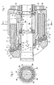
- FIG. 1 shows an axial section through a first embodiment of a Axial piston machine further developed according to the invention.
- Axial piston machine has a drive shaft 3 with which a cylinder drum 2 for example by means of a key-and-groove connection 4 in a rotationally fixed but axial manner moveable connection.
- the cylinder drum 2 points to a common one Circumferential circle evenly radially distributed cylinder bores 5, in which piston 6th are guided axially.
- the pistons 6 each have a spherical head 7, which in a spherical recess 8 of the associated slide shoe 9 is pivotally mounted.
- the pistons 6 are supported against a non-rotating one via the sliding shoes 9 Swashplate 10 from, the pivot angle ⁇ , which is the surface normal of the sliding surface 11 of the swash plate 10 forms with the drive shaft axis 12, defines the piston stroke.
- the Pistons have an axial longitudinal bore 13, which is in the slide shoes 9 trained bore 14 for hydrostatic relief of the sliding shoes with a Pressure pocket 15 is connected to the sole of the shoe.
- the glide shoes are in one annular retraction plate 16 guided, each on a shoulder-like contact surface 17 of the sliding shoes 15 abuts.
- a central bore 18 of the retraction plate 16 is one Partially spherical retraction ball 19 is used, which on a spherical outer surface 20 each swivel angle ⁇ of the swash plate 10 with the retraction plate 16 in connection stands.
- the hold-down device consisting of the retraction plate 16 and the retraction ball 19 16, 19 is inserted via one or more into a recess 21 of the retraction ball Springs 22 acted against the swash plate 10 in the axial direction, so that the Sliding shoes 9 continuously held on the sliding surface 11 of the swash plate 10 are and the sliding shoes 9, especially during a suction stroke, not from the sliding surface 11 lift off.
- the cylinder bores 9 are connected by kidney-shaped connecting channels Control openings 24 and 25 in connection, which are formed in the control plate 26 to the cylinder bores 5 with each revolution of the cylinder drum 2 cyclically to connect high pressure and low pressure line no longer shown.
- the development according to the invention relates to an improvement in the contact pressure Cylinder drum 2 to the control plate 26.
- one or more, in Embodiment six, radially distributed centrifugal bodies 30a to 30f are provided.
- the Centrifugal bodies 30a to 30f are located in the first one shown in FIG. 1 Embodiment within a between the cylinder drum 2 and the drive shaft 3rd formed, annular cavity 31.
- the centrifugal bodies 30a to 30f are between two support rings 32 and 33 acting as counterparts are clamped.
- the first support ring 32 is supported by a bearing ring 28 on a shoulder 34 of the drive shaft 3.
- the second support ring 33 is supported by a further abutment ring 34 on the cylinder drum 2 from.
- At least one of the support rings is preferably shown in FIG. 1 Embodiment of the support ring 32, by means of a spring element 35, e.g. one Belleville washer, axially resiliently supported, so that there is an assembly play between the centrifugal bodies 30a to 30f and the support rings 32 and 33 is balanced and the centrifugal bodies 30a to 30f even at low speeds or at a standstill on supports 32 and 33 issue.
- a spring element 35 e.g. one Belleville washer
- FIG. 2 shows a for better clarification of the arrangement of the centrifugal bodies 30a to 30f partial section along the line A-A in Fig. 1.
- the end faces of the centrifugal bodies 30a to 30f are each radially downward externally conically narrowing inclined surfaces 38 and 39 formed on corresponding the support rings 32 and 33 formed, also conically radially outward constricting second inclined surfaces 38 and 39 are flush.
- centrifugal force F F acts on each of the centrifugal bodies 30a to 30f, which forces the centrifugal body 30a to 30f radially outward.
- the centrifugal force F F is proportional to the square of the speed n of the drive shaft 3 or the cylinder drum 2.
- a normal force F N is introduced into the support rings 32 and 33, which is perpendicular to the surface normal of the inclined surfaces 36, 37 and 38, 39.
- the normal force F N is divided into a radial component F R and an axial component F A. If the centrifugal bodies 30a to 30f are formed symmetrically, the radial force components F R only form internal forces in the support rings 32 and 33.
- the axial component F A leads to the desired pressing of the cylinder drum 2 on the control plate 26.
- the angle of inclination ⁇ which the surface normal of the inclined surfaces 36, 37 and 38, 39 also the drive shaft axis 12 is preferably between 5 ° and 25 °.
- a special one preferred angle of inclination ⁇ is 15 °.
- FIG. 1 has the advantage of being particularly compact Construction, since the existing between the cylinder drum 2 and the drive shaft 3 Cavity 31 for receiving the centrifugal device according to the invention place.
- the inclined surfaces 38, 39 of the centrifugal bodies 30a to 30f cooperate with the inclined surfaces 36, 37 of the support rings 32 and 33 to form a force deflection device which converts the centrifugal force F F acting on the centrifugal bodies 30a to 30d into a contact force acting on the cylinder drum 2 with an in Direction directed to the control plate 26 and implemented with respect to the drive shaft axis 12 axial component F A.
- Fig. 3 shows an axial section of an axial piston machine with a second Embodiment of the training according to the invention. Elements already described are identified by the same reference numerals.
- the centrifugal bodies 30a to 30d also formed in between the cylinder drum 2 and the drive shaft 3 Cavity 31 arranged and designed as segments that complement each other to form a ring.
- the centrifugal bodies 30a to 30f are each in a in the embodiment as a ball bearing trained centrifugal body bearings 40a to 40f at one end in a lintel ring 33 stored.
- the support ring 33 is supported by an abutment ring 34 on the cylinder drum 2 from or is attached to this.
- Each centrifugal body 30a to 30f has a projection 41a to 41f, which engages a step or a shoulder 42 of the drive shaft 3.
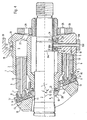
- Fig. 4 shows a section through an axial piston machine 1 with a third Embodiment and a fourth embodiment of the invention Further education. Elements already described have the same reference numerals provided, so that a repetitive description is unnecessary.
- Embodiment of the invention is based on at least one centrifugal body 30a, preferably each of a plurality of radially distributed centrifugal bodies 30a to 30f on the housing 50 the axial piston machine 1.
- Each centrifugal body 30a has the first radially conical outwardly tapering inclined surfaces 38 and 39.
- the housing 50 has one on the Inclined surface 38 of the centrifugal body 30a adapted inclined surface 51, while on the Cylinder drum 2 another adapted to the inclined surface 39 of the centrifugal body 30a Inclined surface 52 is formed.
- the inclined surfaces 38, 39 and 51, 52 are corresponding the embodiment already described with reference to FIG.
- the fourth embodiment of the invention shown in the lower half of FIG. 4 differs from the exemplary embodiment already described with reference to FIG. 1 in that the centrifugal bodies 30a to 30f are not directly between the support rings 32 and 33 are clamped, but that separated from the centrifugal bodies 30a to 30f Caulking bodies 60a to 60f are provided between the support rings 32 and 33. 4 only the centrifugal body 30d and the caulking body 60d are shown.
- the first support ring As in the exemplary embodiment shown in FIG. 1, 32 is based on the shoulder 34 the drive shaft 3, while the second support ring 33 on the bearing ring 34 on the Cylinder drum 2 is supported. Similar to the centrifugal bodies 30a to 30f in FIG.
- the caulking elements 60a to 60f in FIG. 4 have first inclined surfaces 38, 39 at the end, the provided on the support rings 32 and 33 second inclined surfaces 36, 37 in the interact as described above.
- the surface normals are the Sloping surfaces 36, 37 and 38, 39 corresponding to a predetermined angle of inclination inclined with respect to the drive shaft axis 12.
- the angle of inclination is also at this Embodiment preferably between 5 ° and 25 ° and is particularly advantageously 15 °.
- the centrifugal bodies 30a to 30f are arranged on the outer circumference 61 of the cylinder drum 2. Compared to the embodiment shown in FIG. 1, this has the advantage of a greater radial spacing of the centrifugal bodies 30a to 30f relative to the drive shaft axis 12, so that the centrifugal force F F exerted on the centrifugal bodies 30a to 30f is correspondingly greater.
- the centrifugal bodies 30a to 30f are connected to the caulking elements 60a to 60f via radial connecting elements 62a to 62f, only the connecting element 62d being shown in FIG. 4.
- the connecting elements 62a to 62f can be pin-like bolt elements, for example, which extend in radial bores 63a to 63f of the cylinder drum 2, which are passed between the cylinder bores 5.
- the centrifugal bodies 30a to 30f can also be integrated in the cylinder drum 2 or recessed therein. The centrifugal bodies 30a to 30f are particularly advantageously radially flush with the outer diameter 61 of the cylinder drum 2, so that the installation space required is not increased by the measure according to the invention.
- Fig. 4 shows an axial section through an axial piston machine 1 with a fifth Embodiment of the training according to the invention.
- the embodiment largely corresponds to the embodiment already described with reference to FIG. 1. Elements already described are provided with the same reference numerals, so that a repetitive description in this regard is unnecessary.
- FIG. 5 differs from that in FIG. 1 illustrated embodiment in that the first support ring 32 over the first Support ring 28 is not supported on a shoulder 34 of the drive shaft 3, but via one Link on the retraction plate 16 and the retraction ball 19 Hold-down device 16, 19.
- Connecting member made of at least one, preferably several, radially distributed Connecting pins 70 between the support ring 32 and the contact ring 28 and the Retraction ball 19 are arranged.
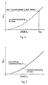
- both the mass force F M exerted by the pistons 6 and the contact pressure F A or F Fe exerted on the cylinder drum 2 against the control plate 26 are shown as a function of the speed in the cylinder drum 2.
- 6 shows a conventional design of the pressure device with a pressure spring.
- the contact pressure or engine preload F Fe exerted by the pressure spring is constant and independent of the speed n.
- the mass force F M exerted by the pistons 6 on the cylinder drum 2 increases with the square of the speed n.
- the maximum speed n max is reached at the latest when the mass force F M exerted by the pistons exceeds the constant spring force F Fe exerted by the pressure device.
- Fig. 7 comparatively speed-dependent Triebwerksvorschreib F A shows the pressing device according to the invention that the axial component F A corresponds to the pressing force. Since the centrifugal force F F is also proportional to the square of the speed n of the cylinder drum 2, it can be achieved with an appropriate design of the pressing device according to the invention that the pressing force F A exerted by the pressing device according to the invention is always greater than the mass force F M exerted by the piston 6. There is therefore no system-related limitation of the maximum speed n max by the pressing device.
- the invention is not limited to the exemplary embodiments shown. In particular can measures of the individual embodiments with each other easily be combined. Various other training courses are also available Force deflection device conceivable.
Landscapes
- Engineering & Computer Science (AREA)
- Physics & Mathematics (AREA)
- Fluid Mechanics (AREA)
- Mechanical Engineering (AREA)
- General Engineering & Computer Science (AREA)
- Reciprocating Pumps (AREA)
Applications Claiming Priority (3)
| Application Number | Priority Date | Filing Date | Title |
|---|---|---|---|
| DE19706263A DE19706263C1 (de) | 1997-02-18 | 1997-02-18 | Axialkolbenmaschine mit drehzahlabhängiger Anpressung der Zylindertrommel |
| DE19706263 | 1997-02-18 | ||
| PCT/EP1998/000550 WO1998037308A1 (de) | 1997-02-18 | 1998-02-02 | Axialkolbenmaschine mit drehzahlabhängiger anpressung der zylindertrommel |
Publications (2)
| Publication Number | Publication Date |
|---|---|
| EP0964980A1 EP0964980A1 (de) | 1999-12-22 |
| EP0964980B1 true EP0964980B1 (de) | 2002-04-17 |
Family
ID=7820648
Family Applications (1)
| Application Number | Title | Priority Date | Filing Date |
|---|---|---|---|
| EP98909381A Expired - Lifetime EP0964980B1 (de) | 1997-02-18 | 1998-02-02 | Axialkolbenmaschine mit drehzahlabhängiger anpressung der zylindertrommel |
Country Status (5)
| Country | Link |
|---|---|
| US (1) | US6244160B1 (enExample) |
| EP (1) | EP0964980B1 (enExample) |
| JP (1) | JP4093324B2 (enExample) |
| DE (2) | DE19706263C1 (enExample) |
| WO (1) | WO1998037308A1 (enExample) |
Families Citing this family (16)
| Publication number | Priority date | Publication date | Assignee | Title |
|---|---|---|---|---|
| DE10154723A1 (de) * | 2000-11-10 | 2002-10-31 | Parker Hannifin Corp | Axialkolbenpumpe mit interner Vorverdichtung |
| US6893228B2 (en) * | 2002-11-22 | 2005-05-17 | Caterpillar Inc | Axial piston pump with fluid bearing arrangement |
| US7007468B1 (en) | 2003-06-27 | 2006-03-07 | Hydro-Gear Limited Partnership | Charge pump for a hydrostatic transmission |
| US7278263B1 (en) | 2003-06-27 | 2007-10-09 | Hydro-Gear Limited Partnership | Charge pump for a hydraulic pump |
| DE102006046128A1 (de) * | 2006-06-02 | 2007-12-06 | Brueninghaus Hydromatik Gmbh | Axialkolbenmaschine mit hydrostatischer Auflage des Niederhalters |
| DE102007049393A1 (de) * | 2007-10-15 | 2009-04-16 | Linde Material Handling Gmbh | Axialkolbenmaschine |
| DE102008009815B4 (de) * | 2008-02-19 | 2016-09-29 | Robert Bosch Gmbh | Rückzugkugel für eine hydrostatische Kolbenmaschine und System aus einer solchen Rückzugskugel und aus einer Vielzahl von Federn |
| DE102010054044A1 (de) * | 2010-12-10 | 2012-06-14 | Robert Bosch Gmbh | System mit Gleitschuhen und Kolben für eine Axialkolbenmaschine |
| DE102013101986B4 (de) | 2013-02-28 | 2023-06-22 | Linde Hydraulics Gmbh & Co. Kg | Hydrostatisches Axialkolbentriebwerk in Schrägscheibenbauweise mit drei unterschiedlichen Federeinrichtungen zur Anpressung der Zylindertrommel an die Steuerfläche und zur kraftschlüssigen Niederhaltung der Triebwerkskolben an der Schrägscheibe |
| DE102013208454A1 (de) | 2013-05-08 | 2014-11-13 | Robert Bosch Gmbh | Hydrostatische Axialkolbenmaschine mit einer Zylindertrommel mit schräg zu deren Axialrichtung gelagerten Arbeitskolben und einem ebenen Steuerspiegel |
| DE102013210416A1 (de) | 2013-06-05 | 2014-12-11 | Robert Bosch Gmbh | Hydrostatische Axialkolbenmaschine und Rückhalteplatte |
| JP6210826B2 (ja) * | 2013-10-03 | 2017-10-11 | Kyb株式会社 | 斜板式ピストンポンプ・モータ |
| JP6612610B2 (ja) * | 2015-12-17 | 2019-11-27 | ナブテスコ株式会社 | 流体圧ポンプおよび流体圧システム |
| CH712152A1 (de) | 2016-02-25 | 2017-08-31 | Liebherr Machines Bulle Sa | Axialkolbenmaschine, insbesondere Axialkolbenpumpe. |
| CH714910A1 (de) * | 2018-04-17 | 2019-10-31 | Liebherr Machines Bulle Sa | Axialkolbenmaschine. |
| DE102023206128A1 (de) * | 2023-06-29 | 2025-01-02 | Robert Bosch Gesellschaft mit beschränkter Haftung | Axialkolbenmaschine mit Rückzugsplatte für hohe Drehzahlen |
Family Cites Families (12)
| Publication number | Priority date | Publication date | Assignee | Title |
|---|---|---|---|---|
| DE1226418B (de) | 1962-07-12 | 1966-10-06 | Unipat A G | Einrichtung zum Andruecken der winkelbeweglichen Kolbengleitschuhe an die Schiefscheibe oder Taumelscheibe einer Axialkolbenmaschine (Pumpe oder Motor) |
| US3657970A (en) * | 1969-06-09 | 1972-04-25 | Toyoda Chuo Kenkyusho Kk | Hydraulic pump or motor having a rotary cylinder barrel |
| BE755124A (fr) * | 1969-08-21 | 1971-02-22 | Caterpillar Tractor Co | Palier de butee pour pompe ou moteur a pistons notamment d'engins de terrassement |
| US3587403A (en) | 1970-01-16 | 1971-06-28 | Sperry Rand Corp | Power transmission |
| DE2116619A1 (de) * | 1971-04-05 | 1972-10-19 | Robert Bosch Gmbh, 7000 Stuttgart | Axialkolbenmaschine |
| DE2134026A1 (de) * | 1971-07-08 | 1973-01-18 | Bosch Gmbh Robert | Axialkolbenmaschine |
| US3810715A (en) * | 1972-08-07 | 1974-05-14 | Gen Motors Corp | Hydrostatic machine valve biasing system |
| DD107116A1 (de) * | 1973-10-01 | 1974-07-12 | Manfred Mueller | Hydrostatische axialkolbenmaschine |
| DE3413059C1 (de) * | 1984-04-06 | 1985-07-11 | Hydromatik GmbH, 7915 Elchingen | Axialkolbenmaschine,insbesondere -pumpe der Schraegscheiben- oder Schraegachsenbauart |
| DE4405034A1 (de) * | 1994-02-17 | 1995-08-24 | Audi Ag | Axialkolben-Taumelscheiben-Kompressor |
| JP3874308B2 (ja) * | 1994-10-18 | 2007-01-31 | 株式会社小松製作所 | 斜板式ピストンポンプ・モータの斜板角度変更装置 |
| DE19522168A1 (de) * | 1995-06-19 | 1997-01-02 | Linde Ag | Axialkolbenmaschine in Schrägscheibenbauweise |
-
1997
- 1997-02-18 DE DE19706263A patent/DE19706263C1/de not_active Expired - Fee Related
-
1998
- 1998-02-02 DE DE59803851T patent/DE59803851D1/de not_active Expired - Lifetime
- 1998-02-02 US US09/355,480 patent/US6244160B1/en not_active Expired - Fee Related
- 1998-02-02 EP EP98909381A patent/EP0964980B1/de not_active Expired - Lifetime
- 1998-02-02 WO PCT/EP1998/000550 patent/WO1998037308A1/de not_active Ceased
- 1998-02-02 JP JP53619098A patent/JP4093324B2/ja not_active Expired - Fee Related
Also Published As
| Publication number | Publication date |
|---|---|
| US6244160B1 (en) | 2001-06-12 |
| DE59803851D1 (de) | 2002-05-23 |
| WO1998037308A1 (de) | 1998-08-27 |
| JP4093324B2 (ja) | 2008-06-04 |
| EP0964980A1 (de) | 1999-12-22 |
| JP2001511865A (ja) | 2001-08-14 |
| DE19706263C1 (de) | 1998-07-23 |
Similar Documents
| Publication | Publication Date | Title |
|---|---|---|
| EP0964980B1 (de) | Axialkolbenmaschine mit drehzahlabhängiger anpressung der zylindertrommel | |
| DE19616961C2 (de) | Hubkolbenmaschine mit Taumelscheibengetriebe | |
| DE3413059C1 (de) | Axialkolbenmaschine,insbesondere -pumpe der Schraegscheiben- oder Schraegachsenbauart | |
| EP0102915B1 (de) | Hydraulischer Radialkolbenmotor | |
| DE2265774C2 (enExample) | ||
| DE4237506C2 (de) | Axialkolbenmaschine | |
| EP2050957A1 (de) | Axialkolbenmaschine | |
| EP2024638A1 (de) | Axialkolbenmaschine mit hydrostatischer auflage des niederhalters | |
| EP1588052B1 (de) | Axialkolbenmaschine mit fixierbarem gleitstein an der schrägscheibe | |
| DE9018185U1 (de) | Gelenkverbinderelement | |
| DE19645580C1 (de) | Axialkolbenmaschine mit Dämpfungselement für die Schräg- oder Taumelscheibe | |
| DE3632906C2 (enExample) | ||
| DE3120812C2 (de) | Radialkolbenverdichter | |
| DE3519822A1 (de) | Einstellbare axialkolbenmaschine | |
| DE102021200205A1 (de) | Axialkolbenmaschine mit hoher Antriebdrehzahl | |
| DE19752021B4 (de) | Hydrostatische Axialkolbenmaschine | |
| DE19620654B4 (de) | Verstellbare Axialkolbenmaschine in Schrägscheibenbauweise | |
| DE19642021B4 (de) | Hydrostatische Axialkolbenmaschine | |
| DE4341845C2 (de) | Hydraulischer Axialkolben-Motor | |
| DE19829060A1 (de) | Hydrostatische Maschine mit Rückstaueinrichtung im Schmierkanal | |
| DE3725156C2 (enExample) | ||
| DE4022858A1 (de) | Axialkolbenmaschine | |
| DE4214397A1 (de) | Hydrostatischer motor mit einer bremseinrichtung | |
| DE102019217204A1 (de) | Axialkolbenmaschine mit in der Verteilplatte gelagerten Antriebswelle | |
| DE19602770C2 (de) | Kolbenrollen-Führung für Radialkolbenaggregat |
Legal Events
| Date | Code | Title | Description |
|---|---|---|---|
| PUAI | Public reference made under article 153(3) epc to a published international application that has entered the european phase |
Free format text: ORIGINAL CODE: 0009012 |
|
| 17P | Request for examination filed |
Effective date: 19990512 |
|
| AK | Designated contracting states |
Kind code of ref document: A1 Designated state(s): DE FR GB IT SE |
|
| GRAG | Despatch of communication of intention to grant |
Free format text: ORIGINAL CODE: EPIDOS AGRA |
|
| GRAG | Despatch of communication of intention to grant |
Free format text: ORIGINAL CODE: EPIDOS AGRA |
|
| GRAH | Despatch of communication of intention to grant a patent |
Free format text: ORIGINAL CODE: EPIDOS IGRA |
|
| 17Q | First examination report despatched |
Effective date: 20010726 |
|
| GRAH | Despatch of communication of intention to grant a patent |
Free format text: ORIGINAL CODE: EPIDOS IGRA |
|
| REG | Reference to a national code |
Ref country code: GB Ref legal event code: IF02 |
|
| GRAA | (expected) grant |
Free format text: ORIGINAL CODE: 0009210 |
|
| AK | Designated contracting states |
Kind code of ref document: B1 Designated state(s): DE FR GB IT SE |
|
| GBT | Gb: translation of ep patent filed (gb section 77(6)(a)/1977) |
Effective date: 20020417 |
|
| REF | Corresponds to: |
Ref document number: 59803851 Country of ref document: DE Date of ref document: 20020523 |
|
| ET | Fr: translation filed | ||
| PLBE | No opposition filed within time limit |
Free format text: ORIGINAL CODE: 0009261 |
|
| STAA | Information on the status of an ep patent application or granted ep patent |
Free format text: STATUS: NO OPPOSITION FILED WITHIN TIME LIMIT |
|
| 26N | No opposition filed |
Effective date: 20030120 |
|
| PGFP | Annual fee paid to national office [announced via postgrant information from national office to epo] |
Ref country code: SE Payment date: 20080214 Year of fee payment: 11 Ref country code: GB Payment date: 20080220 Year of fee payment: 11 |
|
| PGFP | Annual fee paid to national office [announced via postgrant information from national office to epo] |
Ref country code: FR Payment date: 20080214 Year of fee payment: 11 |
|
| EUG | Se: european patent has lapsed | ||
| GBPC | Gb: european patent ceased through non-payment of renewal fee |
Effective date: 20090202 |
|
| REG | Reference to a national code |
Ref country code: FR Ref legal event code: ST Effective date: 20091030 |
|
| PG25 | Lapsed in a contracting state [announced via postgrant information from national office to epo] |
Ref country code: GB Free format text: LAPSE BECAUSE OF NON-PAYMENT OF DUE FEES Effective date: 20090202 Ref country code: FR Free format text: LAPSE BECAUSE OF NON-PAYMENT OF DUE FEES Effective date: 20090302 |
|
| PG25 | Lapsed in a contracting state [announced via postgrant information from national office to epo] |
Ref country code: SE Free format text: LAPSE BECAUSE OF NON-PAYMENT OF DUE FEES Effective date: 20090203 |
|
| PGFP | Annual fee paid to national office [announced via postgrant information from national office to epo] |
Ref country code: IT Payment date: 20110224 Year of fee payment: 14 |
|
| PGFP | Annual fee paid to national office [announced via postgrant information from national office to epo] |
Ref country code: DE Payment date: 20110421 Year of fee payment: 14 |
|
| PG25 | Lapsed in a contracting state [announced via postgrant information from national office to epo] |
Ref country code: IT Free format text: LAPSE BECAUSE OF NON-PAYMENT OF DUE FEES Effective date: 20120202 |
|
| REG | Reference to a national code |
Ref country code: DE Ref legal event code: R119 Ref document number: 59803851 Country of ref document: DE Effective date: 20120901 |
|
| PG25 | Lapsed in a contracting state [announced via postgrant information from national office to epo] |
Ref country code: DE Free format text: LAPSE BECAUSE OF NON-PAYMENT OF DUE FEES Effective date: 20120901 |