EP0964980B1 - Axial piston machine with rpm-dependent pressure acting against the cylinder drum - Google Patents
Axial piston machine with rpm-dependent pressure acting against the cylinder drum Download PDFInfo
- Publication number
- EP0964980B1 EP0964980B1 EP98909381A EP98909381A EP0964980B1 EP 0964980 B1 EP0964980 B1 EP 0964980B1 EP 98909381 A EP98909381 A EP 98909381A EP 98909381 A EP98909381 A EP 98909381A EP 0964980 B1 EP0964980 B1 EP 0964980B1
- Authority
- EP
- European Patent Office
- Prior art keywords
- drive shaft
- cylinder drum
- force
- centrifugal
- piston machine
- Prior art date
- Legal status (The legal status is an assumption and is not a legal conclusion. Google has not performed a legal analysis and makes no representation as to the accuracy of the status listed.)
- Expired - Lifetime
Links
Images


Classifications
-
- F—MECHANICAL ENGINEERING; LIGHTING; HEATING; WEAPONS; BLASTING
- F01—MACHINES OR ENGINES IN GENERAL; ENGINE PLANTS IN GENERAL; STEAM ENGINES
- F01B—MACHINES OR ENGINES, IN GENERAL OR OF POSITIVE-DISPLACEMENT TYPE, e.g. STEAM ENGINES
- F01B3/00—Reciprocating-piston machines or engines with cylinder axes coaxial with, or parallel or inclined to, main shaft axis
- F01B3/0032—Reciprocating-piston machines or engines with cylinder axes coaxial with, or parallel or inclined to, main shaft axis having rotary cylinder block
- F01B3/0041—Arrangements for pressing the cylinder barrel against the valve plate, e.g. fluid pressure
Description
Die Erfindung betrifft eine Axialkolbenmaschine nach dem Oberbegriff des Anspruchs 1.The invention relates to an axial piston machine according to the preamble of claim 1.
Eine Axialkolbenmaschine nach dem Oberbegriff des Anspruchs 1 ist z.B. aus der DE 195 22 168 A 1 bekannt. Die dort offenbarte Axialkolbenmaschine besteht aus einer in einem Gehäuse um eine Triebwellenachse drehbar gelagerten Triebwelle, einer mit der Triebwelle drehfest verbundenen Zylindertrommel, in welcher Zylinder zur Aufnahme von axial beweglichen Kolben ausgebildet sind, und einer Steuerplatte mit Steueröffnungen zur zyklischen Verbindung der Zylinder mit einer Hoch- und einer Niederdruckleitung. Des weiteren ist eine Anpreßeinrichtung vorgesehen, um die Zylindertrommel gegen die Steuerplatte zu pressen und somit gegen die Steuerplatte vorzuspannen. Diese Vorspannung der rotierenden Zylindertrommel gegenüber der stationären Steuerplatte ist erforderlich, um einen dichtenden Abschluß zwischen der Zylindertrommel und der Steuerplatte zu gewährleisten und um einem Abheben der Zylindertrommel von der Steuerplatte bei hohen Drehzahlen entgegenzuwirken. Insbesondere muß ein nicht zentrisches Auswandern der Zylindertrommel bei hohen Drehzahlen sicher verhindert werden.An axial piston machine according to the preamble of claim 1 is e.g. from DE 195 22 168 A 1 known. The axial piston machine disclosed there consists of one in one Housing rotatably mounted about a drive shaft axis, one with the Drive shaft rotatably connected cylinder drum, in which cylinder for receiving axially movable pistons are formed, and a control plate with control openings for Cyclic connection of the cylinders with a high and a low pressure line. Of further a pressing device is provided to the cylinder drum against the To press control plate and thus to bias against the control plate. This The rotating cylinder drum is preloaded against the stationary control plate required to provide a sealing seal between the cylinder drum and the To ensure control plate and to lift the cylinder drum from the Counteract control plate at high speeds. In particular, one does not have to centric migration of the cylinder drum reliably prevented at high speeds become.
Die aus der DE 195 22 168 A1 bekannte Anpreßeinrichtung besteht im wesentlichen aus einer in dem Hohlraum zwischen der Triebwelle und der Zylindertrommel vorgesehenen Anpreßfeder, die sich an ihrem einen Ende an der Triebwelle und an ihrem anderen Ende an der Zylindertrommel abstützt und somit die Zylindertrommel gegenüber einem Anschlußblock, an welchem die Triebwelle gelagert ist und in welchem die Steueröffnungen vorgesehen sind, vorspannt. Durch die Anpreßfeder wird jedoch eine von der Drehzahl unabhängige, konstante Anpreßkraft auf die Zylindertrommel ausgeübt. Dies ist insofern nachteilig, als die erforderliche Anpreßkraft durch die von den Kolben ausgeübten Massenträgheitskräfte vorgegeben ist, die mit dem Quadrat der Betriebsdrehzahl der Zylindertrommel ansteigen. Die von der Anpreßfeder ausgeübte Anpreßkraft muß daher auf die Maximaldrehzahl der Zylindertrommel ausgelegt werden und entsprechend groß bemessen sein. Dies hat jedoch notwendigerweise zur Folge, daß die von der Anpreßfeder ausgeübte Anpreßkraft auch bei kleinen Drehzahlen in gleicher Weise wirksam ist. Dies führt zu mechanischen Reibungsverlusten und zu einem erhöhten Verschleiß der aus der Zylindertrommel und der Steuerplatte bestehenden Gleitpartner. Bei einer Steigerung der maximalen Betriebsdrehzahl muß gleichzeitig auch die von der Anpreßfeder ausgeübte Federvorspannung erhöht werden, was nur in gewissen Grenzen möglich ist.The pressure device known from DE 195 22 168 A1 consists essentially of one provided in the cavity between the drive shaft and the cylinder drum Contact spring, which is at one end to the drive shaft and at the other end is supported on the cylinder drum and thus the cylinder drum opposite one Terminal block on which the drive shaft is mounted and in which the Control openings are provided, prestressed. By the pressure spring, however, one of independent, constant contact pressure exerted on the cylinder drum. This is disadvantageous in that the pressing force required by the piston Exerted inertia forces is given, which is with the square of The operating speed of the cylinder drum increases. The one exerted by the pressure spring Contact pressure must therefore be designed for the maximum speed of the cylinder drum and be sized accordingly. However, this necessarily means that the contact pressure exerted by the contact spring even at low speeds in the same Way is effective. This leads to mechanical friction losses and increased Wear of the sliding partners consisting of the cylinder drum and the control plate. at an increase in the maximum operating speed must also that of the Pressure spring applied spring preload can be increased, which is only within certain limits is possible.
In der EP 0 162 238 B1 wird daher vorgeschlagen, an der Zylindertrommel umfänglich verteilte Hydraulik-Hilfszylinder anzuordnen, deren Arbeitsräume mit den Zylinderbohrungen der Hauptzylinder verbunden sind. Mittels des Hilfszylinders wird eine arbeitsdruck- und damit drehzahlabhängige Anpressung der Zylindertrommel erzielt. Nachteilig bei dieser Lösung ist jedoch der relativ hohe Aufwand zur Ausbildung der zusätzlichen Hydraulikzylinder, was zu relativ hohen Fertigungskosten führt. Ferner wird der benötigte Bauraum für die Axialkolbenmaschine vergrößert.EP 0 162 238 B1 therefore proposes circumferentially on the cylinder drum to arrange distributed hydraulic auxiliary cylinders, their working spaces with the Cylinder bores of the master cylinder are connected. Using the auxiliary cylinder Working pressure and thus speed-dependent pressing of the cylinder drum achieved. A disadvantage of this solution, however, is the relatively high outlay for training the additional hydraulic cylinders, which leads to relatively high manufacturing costs. Furthermore, the space required for the axial piston machine is increased.
In der DE 195 22 168 A1 wird noch vorgeschlagen, eine sich mit zunehmender Drehzahl erhöhende Zusatzanpressung dadurch zu erzielen, daß der Leckraum des Gehäuses gedrosselt mit der Leckölabflußleitung verbunden wird. Der sich dadurch in dem Leckölraum des Axialkolbenmaschinengehäuses einstellende Staudruck bewirkt eine zusätzliche geringfügige axiale Kraftkomponente, mit welcher die Zylindertrommel in Richtung auf den Anschlußblock gedrückt wird. Diese zusätzliche Kraftkomponente ist jedoch vergleichsweise gering, da die Gehäusewandung einer konventionellen Axialkolbenmaschine nur einem relativ geringen Innendruck standhält. Ferner ergibt sich das Problem, daß bei einem hohen Füllstand des Lecköls Planschverluste oder Verwirbelungsverluste auftreten, wenn das Triebwerk in das Lecköl eintaucht.DE 195 22 168 A1 also proposes that the speed increase to achieve additional additional pressure in that the leakage space of the housing is throttled connected to the drain line. Which thereby in the Back pressure setting the leakage oil space of the axial piston machine housing causes a additional minor axial force component with which the cylinder drum in Direction is pressed on the connection block. This additional force component is however comparatively small, since the housing wall of a conventional Axial piston machine withstands only a relatively low internal pressure. It also follows the problem that at a high fill level of the leak oil splashing or Swirl losses occur when the engine is immersed in the leak oil.
Ergänzend wird noch auf die DE-OS 24 46 535 hingewiesen, aus welcher es bekannt ist, mittels einer Fliehkrafteinrichtung auf die Niederhaltevorrichtung zum Andrücken der Gleitschuhe auf die Schrägscheibe einzuwirken. Dazu sind Fliehgewichte am Umfang der Zylindertrommel angeordnet, die über ein Gestänge und einen Andruckteller auf die Rückzugkugel der Niederhaltevorrichtung einwirken. Diese Fliehkraftvorrichtung dient jedoch lediglich zum Andrücken der Gleitschuhe an die Schrägscheibe der Axialkolbenmaschine, wozu vergleichsweise wesentlich geringere Kräfte notwendig sind als zum Anpressen der Zylindertrommel an die Steuerplatte. Ferner hat die Fliehkraftvorrichtung einen relativ geringen Wirkungsgrad, da das die Zylindertrommel durchdringende Gestänge in radialer Richtung geneigt ist und daher nur eine relativ kleine axiale Kraftkomponente auf die Niederhaltevorrichtung übertragen wird. Durch die zusätzlichen Konstruktionselemente des Gestänges und des Andrucktellers ist die Konstruktion relativ aufwendig und kostenintensiv. Die Anordnung der Fliehgewichte im Außendurchmesser führt ferner zu einer unerwünschten Vergrößerung des Bauraums der Axialkolbenmaschine. Ferner wird das Montagespiel in den Fliehgewichten von den umgebenden Hilfs- bzw. Druckelementen nicht ausgeglichen. Daher ist bei relativ geringen Drehzahlen und bei Beschleunigungsvorgängen aus dem Stillstand die Anlage der Fliehgewichte an den Stützelementen bzw. Druckelementen und somit eine Einwirkung der Fliehgewichte auf die Vorrichtung nicht sicher gewährleistet. Die Folge ist eine unzureichende Anpressung der Gleitschuhe im niedrigen Drehzahlbereich.In addition, reference is made to DE-OS 24 46 535, from which it is known by means of a centrifugal force device on the hold-down device for pressing the To act on the swashplate. There are flyweights on the circumference of the Cylinder drum arranged on the by a linkage and a pressure plate Actuate the retraction ball of the hold-down device. This centrifugal device is used however only for pressing the sliding shoes against the swashplate of the Axial piston machine, which requires comparatively much lower forces than for pressing the cylinder drum onto the control plate. Furthermore, the Centrifugal device has a relatively low efficiency, since that is the cylinder drum penetrating linkage is inclined in the radial direction and therefore only a relatively small axial force component is transmitted to the hold-down device. Through the additional construction elements of the linkage and the pressure plate is the Construction is relatively complex and expensive. The arrangement of the flyweights in Outside diameter also leads to an undesirable increase in the installation space Axial piston. Furthermore, the assembly play in the flyweights by the surrounding auxiliary or pressure elements are not balanced. Therefore, at relative low speeds and when accelerating from standstill the system of Flyweights on the support elements or pressure elements and thus an effect of Flying weights on the device are not guaranteed. The consequence is one insufficient contact pressure of the sliding shoes in the low speed range.
Aus der DE-PS 1 226 418 ist es bekannt, zum Andrücken der Gleitschuhe an die Schrägscheibe eine mit einem Hebelarm versehene Fliehkraftvorrichtung vorzusehen, die ebenfalls Fliehgewichte am Außendurchmesser der Zylindertrommel aufweist. Die Krafteinleitung ist auch bei dieser Vorrichtung sehr aufwendig. Für das drehzahlabhängige Anpressen der Zylindertrommel an die Steuerplatte ergeben sich vollkommen andere Kräftebereiche als sie bei Niederhaltevorrichtungen gegeben sind, die dem Andrücken der Gleitschuhe auf die Schrägscheibe dienen. Die aus den vorstehenden Druckschriften bekannten Fliehkraftvorrichtungen sind daher zur Lösung des der Erfindung zugrunde liegenden Problems in keinster Weise geeignet.From DE-PS 1 226 418 it is known to press the sliding shoes against the Swashplate to provide a centrifugal device provided with a lever arm, the also has flyweights on the outer diameter of the cylinder drum. The Force transmission is also very complex in this device. For the speed-dependent Pressing the cylinder drum against the control plate results in completely different situations Force ranges than they are given in the case of holding-down devices which are the pressing of the Serve sliding shoes on the swash plate. The from the above publications Known centrifugal devices are therefore used to solve the problem of the invention problem in any way.
Der Erfindung liegt die Aufgabe zugrunde, eine Axialkolbenmaschine mit einer Anpreßeinrichtung zum Anpressen der Zylindertrommel an die Steuerplatte anzugeben, bei welcher eine unnötig hohe Anpressung im niedrigen Drehzahlbereich vermieden ist und die konstruktiv einfach ausgestaltet ist. The invention has for its object an axial piston machine with a Specify pressure device for pressing the cylinder drum to the control plate, at which avoids unnecessarily high contact pressure in the low speed range and which is structurally simple.
Die Aufgabe wird durch die kennzeichnenden Merkmale der Ansprüche 1 und 3 in Verbindung
mit den gattungsbildenden Merkmalen gelöst.The object is connected by the characterizing features of
Der Erfindung liegt die Erkenntnis zugrunde, daß eine Anpreßeinrichtung mit einer drehzahlabhängigen Anpreßkraft zum Anpressen der Zylindertrommel gegen die Steuerplatte in einfacher Weise durch Verwendung von Fliehkörpern realisiert werden kann, die über eine Kraftumlenkeinrichtung die Fliehkraft in eine an der Zylindertrommel angreifende Anpreßkraft mit einer in Richtung auf die Steuerplatte gerichteten und bezüglich der Triebwellenachse axialen Kraftkomponente umsetzen. Dadurch wird eine unnötig hohe Anpreßkraft im niedrigen Drehzahlbereich vermieden und die Reibungsverluste minimiert. Ferner ergibt sich ein geringer Verschleiß an den Dicht- und Gleitstellen. Im Gegensatz zum Anpressen mittels einer konstanten Federkraft ergibt sich keine durch die Anpreßeinrichtung bedingte Begrenzung der Maximaldrehzahl, da die Anpreßkraft mit ansteigender Drehzahl fortwährend steigt.The invention is based on the finding that a pressure device with a speed-dependent contact pressure for pressing the cylinder drum against the Control plate can be realized in a simple manner by using centrifugal bodies can, the centrifugal force in a on the cylinder drum attacking contact pressure with a directed towards the control plate and implement axial force component with respect to the drive shaft axis. This will make one unnecessarily high contact pressure in the low speed range avoided and the Minimized friction losses. Furthermore, there is little wear on the sealing and Sliding points. In contrast to pressing with a constant spring force, this results no limitation of the maximum speed due to the pressing device, since the Contact force increases continuously with increasing speed.
Die Ansprüche 2 bzw. 4 bis 14 beinhalten vorteilhafte Weiterbildungen der Erfindung.
Entsprechend Anspruch 2 kann sich die Kraftumlenkeinrichtung an der Triebwelle
abstützen und zusammen mit den Fliehkörpern in einem Hohlraum zwischen der
Zylindertrommel und der Triebwelle angeordnet sein, was zu einer besonders kompakten
Bauform führt. Entsprechend Anspruch 3 ist es jedoch auch denkbar, daß sich die
Kraftumlenkeinrichtung an dem Gehäuse der Axialkolbenmaschine abstützt.According to
Entsprechend Anspruch 4 kann an dem Fliehkörper oder einem mit dem Fliehkörper
verbundenen Stemmelement eine Schrägfläche vorgesehen sein, deren Flächennormale
gegenüber der Triebwellenachse mit einem vorgegebenen Neigungswinkel geneigt ist. In
entsprechender Weise kann nach Anspruch 5 die Schrägfläche auch an einem mit dem
Fliehkörper bzw. dem Stemmelement in Wirkverbindung stehenden Gegenstück
vorgesehen sein. Durch die aufgrund des Neigungswinkels der Schrägfläche auftretende
Keilwirkung wird die in radiale Richtung gerichtete Fliehkraft in eine axiale
Kraftkomponente umgesetzt. Entsprechend Anspruch 6 liegt der Neigungswinkel, den die
Flächennormale der Schrägfläche mit der Triebwellenachse bildet, vorzugsweise im
Bereich zwischen 5° und 25°. Ein bevorzugter Wert ist 15°.According to claim 4 can on the centrifugal body or one with the centrifugal body
connected caulking element be provided, the surface normal
is inclined with respect to the drive shaft axis with a predetermined angle of inclination. In
Correspondingly, according to
Entsprechend Anspruch 7 kann das Stemmelement in dem Hohlraum zwischen der Zylindertrommel und der Triebwelle integriert sein und über ein radiales Verbindungselement mit dem Fliehkörper verbunden sein. Der Fliehkörper kann dabei am Außenumfang der Zylindertrommel angeordnet sein, so daß auf den Fliehkörper aufgrund der großen radialen Beabstandung von der Triebwellenachse eine besonders große Fliehkraft einwirkt. Der Fliehkörper kann dabei auch innerhalb der Zylindertrommel integriert sein und insbesondere mit der Zylindertrommel radial bündig abschließen.According to claim 7, the caulking element in the cavity between the Cylinder drum and the drive shaft to be integrated and via a radial Connecting element to be connected to the centrifugal body. The centrifugal body can The outer circumference of the cylinder drum must be arranged so that due to the centrifugal body the large radial distance from the drive shaft axis is a particularly large one Centrifugal force acts. The centrifugal body can also be inside the cylinder drum be integrated and in particular close radially flush with the cylinder drum.
Das Gegenstück, mit welchem der Fliehkörper oder das mit dem Fliehkörper verbundene Stemmelement zusammenwirkt, kann aus zwei Stützringen bestehen, wobei sich ein erster Stützring entsprechend Anspruch 8 an der Triebwelle und ein zweiter Stützring an der Zylindertrommel abstützt. In besonders vorteilhafter Weise kann entsprechend Anspruch 9 zumindest einer der Stützringe mittels eines Federelements, z.B. einer Tellerfeder, gegen den Fliehkörper bzw. das Stemmelement vorgespannt sein. Dadurch ergibt sich eine spielfreie Anlage des Fliehkörpers bzw. des Stemmelements an den als Gegenstück wirkenden Stützringen, so daß die erfindungsgemäße fliehkraftabhängige Anpreßkraft auch schon im niedrigen Drehzahlbereich und bei Beschleunigungen aus dem Stillstand heraus wirksam ist.The counterpart with which the centrifugal body or that connected to the centrifugal body Caulking element cooperates, can consist of two support rings, with a first Support ring according to claim 8 on the drive shaft and a second support ring on the Supported cylinder drum. In a particularly advantageous manner, according to claim 9 at least one of the support rings by means of a spring element, e.g. a disc spring, against the centrifugal body or the caulking element be biased. This results in a backlash-free contact of the centrifugal body or the caulking element to the counterpart acting support rings, so that the centrifugal force-dependent contact pressure according to the invention even in the low speed range and when accelerating from standstill is effective.
Entsprechend Anspruch 10 kann der Fliehkörper einseitig an der Zylindertrommel gelagert
sein und ein Vorsprung des Fliehkörpers an einem Absatz der Triebwelle so angreifen, daß
durch die einsetzende Hebelwirkung die axiale Kraftkomponente der Anpreßkraft auf die
Zylindertrommel ausgeübt wird. In umgekehrter Weise ist es auch denkbar, den
Fliehkörper statt an der Zylindertrommel entsprechend Anspruch 11 an der Triebwelle zu
lagern.According to
Die erfindungsgemäße Fliehkraftvorrichtung kann auch gleichzeitig zu einer
drehzahlabhängigen Erhöhung der Anpreßkraft der Niederhaltevorrichtung zum Andrücken
der Gleitschuhe an die Schrägscheibe entsprechend Anspruch 12 eingesetzt werden. The centrifugal force device according to the invention can also be a
speed-dependent increase in the contact pressure of the hold-down device for pressing
the sliding shoes are used on the swash plate according to
Dadurch wird sichergestellt, daß auch bei hohen Drehzahlen ein Abheben der Gleitschuhe
von der Gleitfläche der Schrägscheibe sicher vermieden wird. Entsprechend den
Ansprüchen 13 und 14 kann die Anpreßkraft für die Niederhaltevorrichtung insbesondere
durch ein zwischen der Rückzugkugel der Niederhaltevorrichtung und der
Kraftumlenkeinrichtung, insbesondere einem der Stützringe, angeordnetes
Verbindungsglied, insbesondere einen axial ausgerichteten Verbindungsstift, vermittelt
werden.This ensures that the sliding shoes lift off even at high speeds
from the sliding surface of the swash plate is safely avoided. According to the
Bevorzugte Ausführungsbeispiele der Erfindung werden nachfolgend unter Bezugnahme auf die Zeichnung näher beschrieben. In der Zeichnung zeigen:
- Fig. 1
- einen axialen Schnitt durch ein erstes Ausführungsbeispiel einer erfindungsgemäßen Axialkolbenmaschine,
- Fig. 2
- einen Schnitt entlang der Linie A-A in Fig. 1,
- Fig. 3
- einen axialen Schnitt durch ein zweites Ausführungsbeispiel einer erfindungsgemäßen Axialkolbenmaschine,
- Fig. 4
- einen axialen Schnitt durch ein drittes Ausführungsbeispiel einer erfindungsgemäßen Axialkolbenmaschine,
- Fig. 5
- einen Schnitt durch ein viertes Ausführungsbeispiel einer erfindungsgemäßen Axialkolbenmaschine,
- Fig. 6
- ein Diagramm zur Erläuterung der von den Kolben ausgeübten Massenträgheitskraft und der Anpreßkraft bei Verwendung einer konventionellen Federanpressung und
- Fig. 7
- ein Diagramm zur Erläuterung der Anpreßkraft bei einer erfindungsgemäß weitergebildeten Axialkolbenmaschine.
- Fig. 1
- 3 shows an axial section through a first exemplary embodiment of an axial piston machine according to the invention,
- Fig. 2
- 2 shows a section along the line AA in FIG. 1,
- Fig. 3
- 3 shows an axial section through a second exemplary embodiment of an axial piston machine according to the invention,
- Fig. 4
- 3 shows an axial section through a third exemplary embodiment of an axial piston machine according to the invention,
- Fig. 5
- 3 shows a section through a fourth exemplary embodiment of an axial piston machine according to the invention,
- Fig. 6
- a diagram for explaining the inertia force exerted by the pistons and the contact pressure when using a conventional spring pressure and
- Fig. 7
- a diagram for explaining the contact pressure in an axial piston machine developed according to the invention.
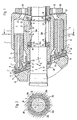
Fig. 1 zeigt einen axialen Schnitt durch ein erstes Ausführungsbeispiel einer
erfindungsgemäß weitergebildeten Axialkolbenmaschine. Die nur auszugsweise dargestellte
Axialkolbenmaschine weist eine Triebwelle 3 auf, mit welcher eine Zylindertrommel 2
beispielsweise mittels einer Keil-Nutverbindung 4 in drehfester, jedoch axial
verschieblicher Verbindung steht. Die Zylindertrommel 2 weist auf einem gemeinsamen
Umfangskreis gleichmäßig radial verteilte Zylinderbohrungen 5 auf, in welchen Kolben 6
axial verschiebbar geführt sind. Die Kolben 6 weisen jeweils einen Kugelkopf 7 auf, der in
einer sphärischen Ausnehmung 8 des zugehörigen Gleitschuhs 9 schwenkbar gelagert ist.
Über die Gleitschuhe 9 stützen sich die Kolben 6 gegen eine nicht rotierende
Schrägscheibe 10 ab, wobei der Schwenkwinkel β, den die Flächennormale der Gleitfläche
11 der Schrägscheibe 10 mit der Triebwellenachse 12 bildet, den Kolbenhub festlegt. Die
Kolben weisen eine Axiallängsbohrung 13 auf, die über eine in den Gleitschuhen 9
ausgebildete Bohrung 14 zur hydrostatischen Entlastung der Gleitschuhe mit einer
Drucktasche 15 an der Gleitschuhsohle verbunden ist. Die Gleitschuhe sind in einer
ringförmigen Rückzugplatte 16 geführt, die jeweils an einer schulterartigen Anlagefläche
17 der Gleitschuhe 15 anliegt. In eine zentrische Bohrung 18 der Rückzugplatte 16 ist eine
teilkugelförmige Rückzugkugel 19 eingesetzt, die an einer sphärischen Außenfläche 20 bei
jedem Schwenkwinkel β der Schrägscheibe 10 mit der Rückzugplatte 16 in Verbindung
steht.Fig. 1 shows an axial section through a first embodiment of a
Axial piston machine further developed according to the invention. The only shown in part
Axial piston machine has a
Die aus der Rückzugplatte 16 und der Rückzugkugel 19 bestehende Niederhaltevorrichtung
16, 19 wird über eine oder mehrere in eine Ausnehmung 21 der Rückzugkugel eingesetzte
Federn 22 in axialer Richtung gegen die Schrägscheibe 10 beaufschlagt, so daß die
Gleitschuhe 9 fortwährend auf der Gleitfläche 11 der Schrägscheibe 10 in Anlage gehalten
werden und die Gleitschuhe 9 insbesondere bei einem Saughub nicht von der Gleitfläche
11 abheben.The hold-down device consisting of the
Die Zylinderbohrungen 9 stehen über Verbindungskanäle mit nierenförmigen
Steueröffnungen 24 und 25 in Verbindung, die in der Steuerplatte 26 ausgebildet sind, um
die Zylinderbohrungen 5 bei jeder Umdrehung der Zylindertrommel 2 zyklisch mit einer
nicht mehr dargestellten Hoch- und Niederdruckleitung zu verbinden. The cylinder bores 9 are connected by kidney-shaped connecting
Die erfindungsgemäße Weiterbildung betrifft eine Verbesserung der Anpressung der
Zylindertrommel 2 an die Steuerplatte 26. Erfindungsgemäß sind ein oder mehrere, im
Ausführungsbeispiel sechs, radial verteilte Fliehkörper 30a bis 30f vorgesehen. Die
Fliehkörper 30a bis 30f befinden sich in dem in Fig. 1 dargestellten, ersten
Ausführungsbeispiel innerhalb eines zwischen der Zylindertrommel 2 und der Triebwelle 3
ausgebildeten, ringförmigen Hohlraums 31. Die Fliehkörper 30a bis 30f sind zwischen
zwei als Gegenstücke wirkenden Stützringen 32 und 33 eingeklemmt. Der erste Stützring
32 stützt sich über einen Anlagering 28 an einem Absatz 34 der Triebwelle 3 ab. Der
zweite Stützring 33 stützt sich über einen weiteren Anlagering 34 an der Zylindertrommel
2 ab. Vorzugsweise ist zumindest einer der Stützringe, im in Fig. 1 dargestellten
Ausführungsbeispiel der Stützring 32, mittels eines Federelementes 35, z.B. einer
Tellerfeder, axial federnd abgestützt, so daß ein Montagespiel zwischen den Fliehkörpern
30a bis 30f und den Stützringen 32 und 33 ausgeglichen ist und die Fliehkörper 30a bis
30f auch bei niedrigen Drehzahlen bzw. im Stillstand an den Stützlingen 32 und 33
anliegen.The development according to the invention relates to an improvement in the contact
Fig. 2 zeigt zur besseren Verdeutlichung der Anordnung der Fliehkörper 30a bis 30f einen
auszugsweisen Schnitt entlang der Linie A-A in Fig. 1. Die Fliehkörper 30a bis 30f bilden
in dem in den Fig. 1 und 2 dargestellten Ausführungsbeispiel jeweils ein Ringsegment. Im
Ruhezustand können die Fliehkörper 30a bis 30f an dem Außenumfang 36 der Triebwelle
3 anliegen. Die Endflächen der Fliehkörper 30a bis 30f sind jeweils als sich radial nach
außen konisch verengende Schrägflächen 38 und 39 ausgebildet, die an entsprechenden an
den Stützringen 32 und 33 ausgebildeten, ebenfalls sich radial nach außen konisch
verengenden zweiten Schrägflächen 38 und 39 bündig anliegen.FIG. 2 shows a for better clarification of the arrangement of the
Mit zunehmender Drehzahl der Triebwelle 3 und der Zylindertrommel 2 wirkt auf jeden
der Fliehkörper 30a bis 30f eine Fliehkraft FF ein, die den Fliehkörper 30a bis 30f radial
nach außen drängt. Die Fliehkraft FF ist dabei dem Quadrat der Drehzahl n der
Triebwelle 3 bzw. der Zylindertrommel 2 proportional. An den geneigten Schrägflächen
38, 39 bzw. 36, 37 wird dabei eine Normalkraft FN in die Stützringe 32 und 33
eingeleitet, die senkrecht zur Flächennormalen der Schrägflächen 36, 37 bzw. 38, 39
steht. In Abhängigkeit von dem Neigungswinkel α, den die Flächennormale n der
Schrägflächen 36, 37 bzw. 38, 39 mit der Triebwellenachse 12 bildet, teilt sich die
Normalkraft FN in eine radiale Komponente FR und eine axiale Komponente FA auf. Bei
symmetrischer Ausbildung der Fliehkörper 30a bis 30f bilden die radialen
Kraftkomponenten FR lediglich innere Kräfte in den Stützringen 32 und 33. Die axiale
Komponente FA führt zu der gewünschten Anpressung der Zylindertrommel 2 an der
Steuerplatte 26.With increasing speed of the
Der Neigungswinkel α, den die Flächennormale der Schrägflächen 36, 37 bzw. 38, 39 mit
der Triebwellenachse 12 bildet, liegt vorzugsweise zwischen 5° und 25°. Ein besonders
bevorzugter Neigungswinkel α ist 15°.The angle of inclination α, which the surface normal of the
Das in Fig. 1 dargestellte Ausführungsbeispiel hat den Vorteil einer besonders kompakten
Bauweise, da der zwischen der Zylindertrommel 2 und der Triebwelle 3 vorhandene
Hohlraum 31 zur Aufnahme der erfindungsgemäßen Fliehkraftvorrichtung Verwendung
findet.The embodiment shown in FIG. 1 has the advantage of being particularly compact
Construction, since the existing between the
Die Schrägflächen 38, 39 der Fliehkörper 30a bis 30f wirken mit den Schrägflächen 36,
37 der Stützringe 32 und 33 zu einer Kraftumlenkeinrichtung zusammen, die die auf die
Fliehkörper 30a bis 30d einwirkende Fliehkraft FF in eine an der Zylindertrommel 2
angreifende Anpreßkraft mit einer in Richtung auf die Steuerplatte 26 gerichteten und
bezüglich der Triebwellenachse 12 axialen Komponente FA umsetzt.The inclined surfaces 38, 39 of the
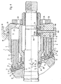
Fig. 3 zeigt einen axialen Schnitt einer Axialkolbenmaschine mit einem zweiten Ausführungsbeispiel der erfindungsgemäßen Weiterbildung. Bereits beschriebene Elemente sind mit übereinstimmenden Bezugszeichen bezeichnet.Fig. 3 shows an axial section of an axial piston machine with a second Embodiment of the training according to the invention. Elements already described are identified by the same reference numerals.
Bei dem in Fig. 3 dargestellten Ausführungsbeispiel sind die Fliehkörper 30a bis 30d
ebenfalls in dem zwischen der Zylindertrommel 2 und der Triebwelle 3 ausgebildeten
Hohlraum 31 angeordnet und als Segmente ausgebildet, die sich zu einem Ring ergänzen.
Die Fliehkörper 30a bis 30f sind jeweils in einer im Ausführungsbeispiel als Kugellager
ausgebildeten Fliehkörperlagerung 40a bis 40f an einem Ende einseitig in einem Stürzring
33 gelagert. Der Stützring 33 stützt sich über einen Anlagering 34 an der Zylindertrommel
2 ab bzw. ist an dieser befestigt. Jeder Fliehkörper 30a bis 30f weist einen Vorsprung 41a
bis 41f auf, der an einer Stufe oder einem Absatz 42 der Triebwelle 3 angreift. Wenn die
Triebwelle 3 und die Zylindertrommel 2 in Rotation versetzt werden, spreizen die
Fliehkörper 30a bis 30f radial nach außen auf, indem die Fliehkörper 30a bis 30f in den
zugehörigen Fliehkörperlagerungen 40a bis 40f um kleine Schwenkwinkel geringfügig
ausschwenken. Die Fliehkörper 30a bis 30f stoßen sich dabei mit ihren Vorsprüngen 41a
bis 41f an dem Absatz 42 der Triebwelle 3 ab, so daß aufgrund der einsetzenden
Hebelwirkung die Fliehkörperlagerung 40a bis 40f mit einer in axialer Richtung wirkenden
Kraftkomponente beaufschlagt wird, die über den Stützring 33 und den Anlagering 34 auf
die Zylindertrommel 2 übertragen wird. Auf diese Weise wird die gewünschte
drehzahlabhängige, axiale Anpreßkraft bewirkt. Als Kraftumlenkeinrichtung dient dabei
die Fliehkörperlagerung 40a bis 40f bzw. der an dem Absatz 42 der Triebwelle 3
angreifende Vorsprung 41a bis 41f.In the embodiment shown in FIG. 3, the
Auch bei dem in Fig. 3 dargestellten Ausfuhrungsbeispiel ergibt sich der besondere Vorteil einer äußerst kompakten Bauweise.The particular advantage also results in the exemplary embodiment shown in FIG. 3 an extremely compact design.
Fig. 4 zeigt einen Schnitt durch eine Axialkolbenmaschine 1 mit einem dritten Ausführungsbeispiel und einem vierten Ausführungsbeispiel der erfindungsgemäßen Weiterbildung. Bereits beschriebene Elemente sind mit übereinstimmenden Bezugszeichen versehen, so daß sich eine wiederholende Beschreibung erübrigt.Fig. 4 shows a section through an axial piston machine 1 with a third Embodiment and a fourth embodiment of the invention Further education. Elements already described have the same reference numerals provided, so that a repetitive description is unnecessary.
Entsprechend einem in der oberen Hälfte der Fig. 4 dargestellten dritten
Ausführungsbeispiel der Erfindung stützt sich zumindest ein Fliehkörper 30a,
vorzugsweise jedpch mehrere radial verteilte Fliehkörper 30a bis 30f, an dem Gehäuse 50
der Axialkolbenmaschine 1 ab. Jeder Fliehkörper 30a weist dabei erste sich radial konisch
nach außen verjüngende Schrägflächen 38 und 39 auf. Das Gehäuse 50 weist eine an die
Schrägfläche 38 des Fliehkörpers 30a angepaßte Schrägfläche 51 auf, während an der
Zylindertrommel 2 eine an die Schrägfläche 39 des Fliehkörpers 30a angepaßte weitere
Schrägfläche 52 ausgebildet ist. Die Schrägflächen 38, 39 und 51, 52 sind entsprechend
dem bereits anhand von Fig. 1 beschriebenen Ausführungsbeispiel gegenüber der
Triebwellenachse 12 geneigt, so daß aufgrund der bereits beschriebenen Keilwirkung die
auf den Fliehkörper 30a einwirkende Fliehkraft in eine Anpreßkraft mit einer axialen
Kraftkomponente umgesetzt wird, die die Zylindertrommel 2 gegen die Steuerplatte 26
preßt. Die Anpreßkraft nimmt auch bei diesem Ausführungsbeispiel mit dem Quadrat der
Drehzahl der Zylindertrommel 2 zu.Corresponding to a third shown in the upper half of FIG. 4
Embodiment of the invention is based on at least one
Das in der unteren Hälfte der Fig. 4 dargestellte vierte Ausführungsbeispiel der Erfindung
unterscheidet sich von dem bereits anhand von Fig. 1 beschriebenen Ausfühningsbeispiel
dadurch, daß nicht unmittelbar die Fliehkörper 30a bis 30f zwischen den Stützringen 32
und 33 eingespannt sind, sondern daß von den Fliehkörpern 30a bis 30f separierte
Stemmkörper 60a bis 60f zwischen den Stützringen 32 und 33 vorgesehen sind. In Fig. 4
ist lediglich der Fliehkörper 30d und der Stemmkörper 60d dargestellt. Der erste Stützring
32 stützt sich wie bei dem in Fig. 1 dargestellten Ausführungsbeispiel an dem Absatz 34
der Triebwelle 3 ab, während sich der zweite Stützring 33 über den Anlagering 34 an der
Zylindertrommel 2 abstützt. In ähnlicher Weise wie die Fliehkörper 30a bis 30f in Fig. 1
weisen die Stemmelemente 60a bis 60f in Fig. 4 endseitig erste Schrägflächen 38, 39 auf,
die mit an den Stützringen 32 und 33 vorgesehenen zweiten Schrägflächen 36, 37 in der
bereits beschriebenen Weise zusammenwirken. Dabei sind die Flächennormalen der
Schrägflächen 36, 37 und 38, 39 entsprechend einem vorgegebenen Neigungswinkel
gegenüber der Triebwellenachse 12 geneigt. Der Neigungswinkel liegt auch bei diesem
Ausführungsbeispiel vorzugsweise zwischen 5° und 25° und beträgt in besonders
vorteilhafter Weise 15°.The fourth embodiment of the invention shown in the lower half of FIG. 4
differs from the exemplary embodiment already described with reference to FIG. 1
in that the
Die Fliehkörper 30a bis 30f sind an dem Außenumfang 61 der Zylindertrommel 2
angeordnet. Dies hat gegenüber dem in Fig. 1 dargestellten Ausführungsbeispiel den
Vorteil einer größeren Radialbeabstandung der Fliehkörper 30a bis 30f gegenüber der
Triebwellenachse 12, so daß die auf die Fliehkörper 30a bis 30f ausgeübte Fliehkraft FF
entsprechend größer ist. Die Fliehkörper 30a bis 30f sind mit den Stemmelementen 60a bis
60f über radiale Verbindungselemente 62a bis 62f verbunden, wobei in Fig. 4 lediglich
das Verbindungselement 62d dargestellt ist. Die Verbindungselemente 62a bis 62f können
z.B. stiftartige Bolzenelemente sein, die sich in Radialbohrungen 63a bis 63f der
Zylindertrommel 2 erstrecken, welche zwischen den Zylinderbohrungen 5 hindurchgeführt
sind. Die Fliehkörper 30a bis 30f können auch in der Zylindertrommel 2 integriert bzw. in
diese versenkt sein. Besonders vorteilhaft schließen die Fliehkörper 30a bis 30f mit dem
Außendurchmesser 61 der Zylindertrommel 2 radial bündig ab, so daß der benötigte
Bauraum durch die erfindungsgemäße Maßnahme nicht vergrößert wird.The
Fig. 4 zeigt einen axialen Schnitt durch eine Axialkolbenmaschine 1 mit einem fünften Ausführungsbeispiel der erfindungsgemäßen Weiterbildung. Das Ausführungsbeispiel entspricht weitgehend dem bereits anhand von Fig. 1 beschriebenen Ausführungsbeispiel. Bereits beschriebene Elemente sind mit übereinstimmenden Bezugszeichen versehen, so daß sich eine diesbezügliche wiederholende Beschreibung erübrigt.Fig. 4 shows an axial section through an axial piston machine 1 with a fifth Embodiment of the training according to the invention. The embodiment largely corresponds to the embodiment already described with reference to FIG. 1. Elements already described are provided with the same reference numerals, so that a repetitive description in this regard is unnecessary.
Das in Fig. 5 dargestellte Ausführungsbeispiel unterscheidet sich von dem in Fig. 1
dargestellten Ausführungsbeispiel dadurch, daß der erste Stützring 32 sich über den ersten
Anlagering 28 nicht an einem Absatz 34 der Triebwelle 3 abstützt, sondern über ein
Verbindungsglied an der aus der Rückzugplatte 16 und der Rückzugkugel 19 bestehenden
Niederhaltevorrichtung 16, 19. Im in Fig. 1 dargestellten Ausführungsbeispiel besteht das
Verbindungsglied aus zumindest einem, vorzugsweise mehreren, radial verteilten
Verbindungsstiften 70, die zwischen dem Stützring 32 bzw. dem Anlagering 28 und der
Rückzugkugel 19 angeordnet sind.The embodiment shown in FIG. 5 differs from that in FIG. 1
illustrated embodiment in that the
Durch die in Fig. 5 dargestellte Weiterbildung läßt sich erreichen, daß auch die
Andrückkraft, mit welcher die Gleitschuhe 9 gegen die Gleitfläche 11 der Schrägscheibe
10 gedrückt werden, mit zunehmender Drehzahl der Triebwelle 3 bzw. der
Zylindertrommel 2 ansteigt. Dadurch wird ein sicheres Anliegen der Gleitschuhe 9 an der
Gleitfläche 11 der Schrägscheibe 10 auch bei hoher Drehzahl der Zylindertrommel 2
sichergestellt und ein Abheben der Gleitschuhe 9 von der Gleitfläche 11 sicher vermieden.5 can be achieved that the
Pressing force with which the sliding
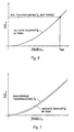
In den Fig. 6 und 7 ist sowohl die von den Kolben 6 ausgeübte Massenkraft FM als auch
die auf die Zylindertrommel 2 gegen die Steuerplatte 26 ausgeübte Anpreßkraft FA bzw.
FFe als Funktion der Drehzahl in der Zylindertrommel 2 dargestellt. Dabei zeigt Fig. 6
eine konventionelle Ausbildung der Anpreßeinrichtung mit einer Anpreßfeder. Die von der
Anpreßfeder ausgeübte Anpreßkraft bzw. Triebwerksvorspannung FFe ist konstant und
unabhängig von der Drehzahl n. Die von den Kolben 6 auf die Zylindertrommel 2
ausgeübte Massenkraft FM wächst jedoch mit dem Quadrat der Drehzahl n an. Spätestens
wenn die von den Kolben ausgeübte Massenkraft FM die von der Anpreßeinrichtung
ausgeübte konstante Federkraft FFe überschreitet, ist die maximale Drehzahl nmax erreicht.6 and 7, both the mass force F M exerted by the
Fig. 7 zeigt vergleichsweise die drehzahlabhängige Triebwerksvorspannung FA der
erfindungsgemäßen Anpreßeinrichtung, die der axialen Komponente FA der Anpreßkraft
entspricht. Da die Fliehkraft FF ebenfalls proportionalzum Quadrat der Drehzahl n der
Zylindertrommel 2 ist, läßt sich bei entsprechender Auslegung der erfindungsgemäßen
Anpreßeinrichtung erreichen, daß die von der erfindungsgemäßen Anpreßeinrichtung
ausgeübte Anpreßkraft FA stets größer ist als die von den Kolben 6 ausgeübte Massenkraft
FM. Eine durch die Anpreßeinrichtung systembedingte Begrenzung der maximalen
Drehzahl nmax besteht daher nicht.Fig. 7 comparatively speed-dependent Triebwerksvorspannung F A shows the pressing device according to the invention that the axial component F A corresponds to the pressing force. Since the centrifugal force F F is also proportional to the square of the speed n of the
Die Erfindung ist nicht auf die dargestellten Ausführungsbeispiele begrenzt. Insbesondere können Maßnahmen der einzelnen Ausführungsbeispiele ohne weiteres miteinander kombiniert werden. Auch sind verschiedene andere Ausbildungen der Kraftumlenkeinrichtung denkbar.The invention is not limited to the exemplary embodiments shown. In particular can measures of the individual embodiments with each other easily be combined. Various other training courses are also available Force deflection device conceivable.
Claims (14)
- Axial piston machine (1) having
a casing (50),
a drive shaft (3) mounted in the casing (50) so that it can rotate about a drive shaft axis (12),
a cylinder drum (2) which is connected in a rotationally fixed manner to the drive shaft (3) and in which cylinders (5) are formed to accommodate axially movable pistons (6), a control plate (26) with control openings (24, 25) for cyclically connecting the cylinders (5) to a high-pressure and a low-pressure line,
a pressing-on device for preloading the cylinder drum (2) against the control plate (26), the pressing-on device comprising at least one centrifugal body (30a - 30f) which is subjected to an increasing centrifugal force (FF) as the speed (n) of the cylinder drum (2) increases, and
at least one force redirection device (36 - 39; 40a - 40f, 41a - 41f) for redirecting the centrifugal force (FF) acting on the centrifugal body (30a - 30f) into a pressing-on force which is applied to the cylinder drum (2) and has a component (FA) which is directed towards the control plate (26) and is axial with respect to the drive shaft axis (12),
characterised in that the force redirection device (36 - 39) is arranged in a cavity (31) between the cylinder drum (2) and the drive shaft (3). - Axial piston machine according to Claim 1, characterised in that each force redirection device (36 - 39) is supported on the drive shaft (3) and the cylinder drum (2).
- Axial piston machine (1) having
a casing (50),
a drive shaft (3) mounted in the casing (50) so that it can rotate about a drive shaft axis (12),
a cylinder drum (2) which is connected in a rotationally fixed manner to the drive shaft (3) and in which cylinders (5) are formed to accommodate axially movable pistons (6), a control plate (26) with control openings (24, 25) for cyclically connecting the cylinders (5) to a high-pressure and a low-pressure line,
a pressing-on device for preloading the cylinder drum (2) against the control plate (26), the pressing-on device comprising at least one centrifugal body (30a - 30f) which is subjected to an increasing centrifugal force (FF) as the speed (n) of the cylinder drum (2) increases, and
at least one force redirection device (36 - 39; 40a - 40f, 41a - 41f) for redirecting the centrifugal force (FF) acting on the centrifugal body (30a - 30f) into a pressing-on force which is applied to the cylinder drum (2) and has a component (FA) which is directed towards the control plate (26) and is axial with respect to the drive shaft axis (12),
characterised in that the force redirection device (37, 38, 51, 52) is supported on the casing (50) and the cylinder drum (2). - Axial piston machine according to one of Claims 1 to 3, characterised in that each force redirection device (37 - 39) has at least one oblique surface (38, 39) which is provided on the centrifugal body (30a - 30f) or a caulking element (60a - 60f) connected to the centrifugal body (30a - 30f), and the surface normal of which is inclined relative to the drive shaft axis (12) at a predetermined angle of inclination (α).
- Axial piston machine according to one of Claims 1 to 4, characterised in that each force redirection device (37 - 39) has at least one oblique surface (36, 37) which is provided on a counterpart (32, 33) operatively connected to the centrifugal body (30a - 30f) or the caulking element (60a - 60f), and the surface normal of which is inclined relative to the drive shaft axis (12) at a predetermined angle of inclination (α).
- Axial piston machine according to Claim 4 or 5, characterised in that the angle of inclination (α) which the surface normal(s) of the oblique surface(s) forms with the drive shaft axis (12) lies in the range between 5° and 25° and is preferably 15°.
- Axial piston machine according to one of Claims 4 to 6, characterised in that the or each caulking element (60a - 60f) is arranged in a cavity (31) between the cylinder drum (2) and the drive shaft (3) and is connected to at least one associated centrifugal body (30a - 30f) via a radial connecting element (62a - 62f).
- Axial piston machine according to Claim 5, characterised in that the counterpart (32, 33) is formed by a first support ring (32) supported on the drive shaft (3) and a second support ring (33) supported on the cylinder drum (2).
- Axial piston machine according to Claim 8, characterised in that at least one (32) of the support rings (32, 33) is preloaded by means of a spring element (35) against the centrifugal body (30a - 30f) or against the caulking element (60a - 60f).
- Axial piston machine according to Claim 1 or 2, characterised in that at least one of the centrifugal bodies (30a - 30f) is mounted on one side of the cylinder drum (2) in a centrifugal body bearing arrangement (40a - 40f), and a projection (41a - 41f) of the centrifugal body (30a - 30f) engages on a shoulder (42) of the drive shaft (3) such that, when the centrifugal body (30a - 30f) pivots out owing to the centrifugal force (FF) acting on it, the axial component (FA) of the pressing-on force is exerted on the centrifugal body bearing arrangement (40a - 40f) acting as the force redirection device.
- Axial piston machine according to Claim 1 or 2, characterised in that at least one of the centrifugal bodies (30a - 30f) is mounted on one side of the drive shaft (3) in a centrifugal body bearing arrangement, and a projection of the centrifugal body engages on a shoulder of the cylinder drum such that, when the centrifugal body (30a - 30f) pivots out owing to the centrifugal force (FF) acting on it, the axial component (FA) of the pressing-on force is exerted on the shoulder, acting as the force redirection device, of the cylinder drum (2).
- Axial piston machine according to one of Claims 1 to 11, characterised in that the pistons (6) are supported on a swash plate (10) via slide shoes (9), in that a holding-down device (16, 19) is provided to keep the slide shoes (9) bearing against the swash plate (11), and in that the axial component (FA) of the pressing-on force additionally acts on the holding-down device (16, 19).
- Axial piston machine according to Claim 12, characterised in that the holding-down device (16, 19) has a pull-back plate (16) bearing against the slide shoes (9), and a pull-back ball (19) bearing against the pull-back plate (16) in every pivoted position of the swash plate (10), and in that the axial component (FA) of the pressing-on force is applied to the holding-down device (16, 19) via a connecting member (70) arranged between the force redirection device (36 - 39; 40a to 40f, 41a - 41f) and the pull-back ball (19).
- Axial piston machine according to Claim 13, characterised in that each connecting member consists of at least one connecting pin (70) which is arranged axially parallel to the drive shaft axis (12) between one of the support rings (32) and the pull-back ball (19).
Applications Claiming Priority (3)
| Application Number | Priority Date | Filing Date | Title |
|---|---|---|---|
| DE19706263 | 1997-02-18 | ||
| DE19706263A DE19706263C1 (en) | 1997-02-18 | 1997-02-18 | Axial piston machine |
| PCT/EP1998/000550 WO1998037308A1 (en) | 1997-02-18 | 1998-02-02 | Axial piston machine with rpm-dependent pressure acting against the cylinder drum |
Publications (2)
| Publication Number | Publication Date |
|---|---|
| EP0964980A1 EP0964980A1 (en) | 1999-12-22 |
| EP0964980B1 true EP0964980B1 (en) | 2002-04-17 |
Family
ID=7820648
Family Applications (1)
| Application Number | Title | Priority Date | Filing Date |
|---|---|---|---|
| EP98909381A Expired - Lifetime EP0964980B1 (en) | 1997-02-18 | 1998-02-02 | Axial piston machine with rpm-dependent pressure acting against the cylinder drum |
Country Status (5)
| Country | Link |
|---|---|
| US (1) | US6244160B1 (en) |
| EP (1) | EP0964980B1 (en) |
| JP (1) | JP4093324B2 (en) |
| DE (2) | DE19706263C1 (en) |
| WO (1) | WO1998037308A1 (en) |
Families Citing this family (15)
| Publication number | Priority date | Publication date | Assignee | Title |
|---|---|---|---|---|
| DE10154723A1 (en) * | 2000-11-10 | 2002-10-31 | Parker Hannifin Corp | Axial piston pump has vanes in cylinder protruding radially outwards and finishing with radially outer edge adjacent to inner wall surface of cylinder chamber, and when cylinder rotates vanes effect pre-compression of fluid |
| US6893228B2 (en) * | 2002-11-22 | 2005-05-17 | Caterpillar Inc | Axial piston pump with fluid bearing arrangement |
| US7007468B1 (en) | 2003-06-27 | 2006-03-07 | Hydro-Gear Limited Partnership | Charge pump for a hydrostatic transmission |
| US7278263B1 (en) | 2003-06-27 | 2007-10-09 | Hydro-Gear Limited Partnership | Charge pump for a hydraulic pump |
| DE102006046128A1 (en) * | 2006-06-02 | 2007-12-06 | Brueninghaus Hydromatik Gmbh | Axial piston machine with hydrostatic support of the downholder |
| DE102007049393A1 (en) * | 2007-10-15 | 2009-04-16 | Linde Material Handling Gmbh | axial piston |
| DE102008009815B4 (en) | 2008-02-19 | 2016-09-29 | Robert Bosch Gmbh | Retraction ball for a hydrostatic piston engine and system of such a retraction ball and a plurality of springs |
| DE102010054044A1 (en) * | 2010-12-10 | 2012-06-14 | Robert Bosch Gmbh | System with sliding blocks and pistons for an axial piston machine |
| DE102013101986B4 (en) | 2013-02-28 | 2023-06-22 | Linde Hydraulics Gmbh & Co. Kg | Hydrostatic axial piston engine in swashplate design with three different spring devices for pressing the cylinder drum against the control surface and for positively holding down the engine pistons on the swashplate |
| DE102013208454A1 (en) | 2013-05-08 | 2014-11-13 | Robert Bosch Gmbh | Hydrostatic axial piston machine with a cylinder drum with obliquely mounted to the axial direction working piston and a flat control mirror |
| DE102013210416A1 (en) | 2013-06-05 | 2014-12-11 | Robert Bosch Gmbh | Hydrostatic axial piston machine and retaining plate |
| JP6210826B2 (en) * | 2013-10-03 | 2017-10-11 | Kyb株式会社 | Swash plate type piston pump motor |
| JP6612610B2 (en) * | 2015-12-17 | 2019-11-27 | ナブテスコ株式会社 | Fluid pressure pump and fluid pressure system |
| CH712152A1 (en) | 2016-02-25 | 2017-08-31 | Liebherr Machines Bulle Sa | Axial piston machine, in particular axial piston pump. |
| CH714910A1 (en) * | 2018-04-17 | 2019-10-31 | Liebherr Machines Bulle Sa | Axial piston. |
Family Cites Families (12)
| Publication number | Priority date | Publication date | Assignee | Title |
|---|---|---|---|---|
| DE1226418B (en) | 1962-07-12 | 1966-10-06 | Unipat A G | Device for pressing the angularly movable piston sliding blocks against the swash plate or swash plate of an axial piston machine (pump or motor) |
| US3657970A (en) * | 1969-06-09 | 1972-04-25 | Toyoda Chuo Kenkyusho Kk | Hydraulic pump or motor having a rotary cylinder barrel |
| BE755124A (en) * | 1969-08-21 | 1971-02-22 | Caterpillar Tractor Co | THRUST BEARING FOR PUMP OR PISTON MOTOR, ESPECIALLY FOR EARTH-MOVING EQUIPMENT |
| US3587403A (en) * | 1970-01-16 | 1971-06-28 | Sperry Rand Corp | Power transmission |
| DE2116619A1 (en) * | 1971-04-05 | 1972-10-19 | Robert Bosch Gmbh, 7000 Stuttgart | Axial piston machine |
| DE2134026A1 (en) * | 1971-07-08 | 1973-01-18 | Bosch Gmbh Robert | AXIAL PISTON MACHINE |
| US3810715A (en) * | 1972-08-07 | 1974-05-14 | Gen Motors Corp | Hydrostatic machine valve biasing system |
| DD107116A1 (en) * | 1973-10-01 | 1974-07-12 | Manfred Mueller | HYDROSTATIC AXIAL PISTON MACHINE |
| DE3413059C1 (en) * | 1984-04-06 | 1985-07-11 | Hydromatik GmbH, 7915 Elchingen | Axial piston machine, in particular pump of the swashplate or bevel axis type |
| DE4405034A1 (en) * | 1994-02-17 | 1995-08-24 | Audi Ag | Axial piston swash plate compressor |
| JP3874308B2 (en) * | 1994-10-18 | 2007-01-31 | 株式会社小松製作所 | Swash plate angle change device for swash plate type piston pump and motor |
| DE19522168A1 (en) * | 1995-06-19 | 1997-01-02 | Linde Ag | Axial piston with swashplate, e.g. for motor |
-
1997
- 1997-02-18 DE DE19706263A patent/DE19706263C1/en not_active Expired - Fee Related
-
1998
- 1998-02-02 DE DE59803851T patent/DE59803851D1/en not_active Expired - Lifetime
- 1998-02-02 US US09/355,480 patent/US6244160B1/en not_active Expired - Fee Related
- 1998-02-02 EP EP98909381A patent/EP0964980B1/en not_active Expired - Lifetime
- 1998-02-02 JP JP53619098A patent/JP4093324B2/en not_active Expired - Fee Related
- 1998-02-02 WO PCT/EP1998/000550 patent/WO1998037308A1/en active IP Right Grant
Also Published As
| Publication number | Publication date |
|---|---|
| DE19706263C1 (en) | 1998-07-23 |
| US6244160B1 (en) | 2001-06-12 |
| JP2001511865A (en) | 2001-08-14 |
| DE59803851D1 (en) | 2002-05-23 |
| WO1998037308A1 (en) | 1998-08-27 |
| EP0964980A1 (en) | 1999-12-22 |
| JP4093324B2 (en) | 2008-06-04 |
Similar Documents
| Publication | Publication Date | Title |
|---|---|---|
| EP0964980B1 (en) | Axial piston machine with rpm-dependent pressure acting against the cylinder drum | |
| DE19616961C2 (en) | Reciprocating piston machine with swash plate gear | |
| DE3413059C1 (en) | Axial piston machine, in particular pump of the swashplate or bevel axis type | |
| EP0102915B1 (en) | Radial-piston hydraulic engine | |
| DE2265774C2 (en) | ||
| EP2050957B1 (en) | Axial piston machine | |
| DE4237506C2 (en) | Axial piston machine | |
| EP2024638A1 (en) | Axial piston machine having a hydrostatic support of the hold-down | |
| DE3519783A1 (en) | AXIAL PISTON MACHINE | |
| DE19645580C1 (en) | Axial piston machine with damping element for the swashplate or swash plate | |
| DE3632906C2 (en) | ||
| DE4424609B4 (en) | Hydraulic axial piston machine | |
| DE1500389C3 (en) | Hydrostatic radial piston gear with internal power split | |
| DE3120812C2 (en) | Radial piston compressor | |
| DE3519822A1 (en) | ADJUSTABLE AXIAL PISTON | |
| DE19752021B4 (en) | Hydrostatic axial piston machine | |
| DE19620654B4 (en) | Adjustable axial piston machine with swashplate design | |
| DE4341845C2 (en) | Hydraulic axial piston motor | |
| DE19829060A1 (en) | Hydrostatic machine with lubrication | |
| DE102019217204A1 (en) | Axial piston machine with drive shaft mounted in the distributor plate | |
| WO2000075511A1 (en) | Swash-plate drag bearing | |
| DE3725156C2 (en) | ||
| DE19642021B4 (en) | Hydrostatic axial piston machine | |
| DE19602770C2 (en) | Piston roller guide for radial piston unit | |
| DE4022858A1 (en) | Axial piston machine - with pistons running on cam track with two top and two bottom dead-centres |
Legal Events
| Date | Code | Title | Description |
|---|---|---|---|
| PUAI | Public reference made under article 153(3) epc to a published international application that has entered the european phase |
Free format text: ORIGINAL CODE: 0009012 |
|
| 17P | Request for examination filed |
Effective date: 19990512 |
|
| AK | Designated contracting states |
Kind code of ref document: A1 Designated state(s): DE FR GB IT SE |
|
| GRAG | Despatch of communication of intention to grant |
Free format text: ORIGINAL CODE: EPIDOS AGRA |
|
| GRAG | Despatch of communication of intention to grant |
Free format text: ORIGINAL CODE: EPIDOS AGRA |
|
| GRAH | Despatch of communication of intention to grant a patent |
Free format text: ORIGINAL CODE: EPIDOS IGRA |
|
| 17Q | First examination report despatched |
Effective date: 20010726 |
|
| GRAH | Despatch of communication of intention to grant a patent |
Free format text: ORIGINAL CODE: EPIDOS IGRA |
|
| REG | Reference to a national code |
Ref country code: GB Ref legal event code: IF02 |
|
| GRAA | (expected) grant |
Free format text: ORIGINAL CODE: 0009210 |
|
| AK | Designated contracting states |
Kind code of ref document: B1 Designated state(s): DE FR GB IT SE |
|
| GBT | Gb: translation of ep patent filed (gb section 77(6)(a)/1977) |
Effective date: 20020417 |
|
| REF | Corresponds to: |
Ref document number: 59803851 Country of ref document: DE Date of ref document: 20020523 |
|
| ET | Fr: translation filed | ||
| PLBE | No opposition filed within time limit |
Free format text: ORIGINAL CODE: 0009261 |
|
| STAA | Information on the status of an ep patent application or granted ep patent |
Free format text: STATUS: NO OPPOSITION FILED WITHIN TIME LIMIT |
|
| 26N | No opposition filed |
Effective date: 20030120 |
|
| PGFP | Annual fee paid to national office [announced via postgrant information from national office to epo] |
Ref country code: SE Payment date: 20080214 Year of fee payment: 11 Ref country code: GB Payment date: 20080220 Year of fee payment: 11 |
|
| PGFP | Annual fee paid to national office [announced via postgrant information from national office to epo] |
Ref country code: FR Payment date: 20080214 Year of fee payment: 11 |
|
| EUG | Se: european patent has lapsed | ||
| GBPC | Gb: european patent ceased through non-payment of renewal fee |
Effective date: 20090202 |
|
| REG | Reference to a national code |
Ref country code: FR Ref legal event code: ST Effective date: 20091030 |
|
| PG25 | Lapsed in a contracting state [announced via postgrant information from national office to epo] |
Ref country code: GB Free format text: LAPSE BECAUSE OF NON-PAYMENT OF DUE FEES Effective date: 20090202 Ref country code: FR Free format text: LAPSE BECAUSE OF NON-PAYMENT OF DUE FEES Effective date: 20090302 |
|
| PG25 | Lapsed in a contracting state [announced via postgrant information from national office to epo] |
Ref country code: SE Free format text: LAPSE BECAUSE OF NON-PAYMENT OF DUE FEES Effective date: 20090203 |
|
| PGFP | Annual fee paid to national office [announced via postgrant information from national office to epo] |
Ref country code: IT Payment date: 20110224 Year of fee payment: 14 |
|
| PGFP | Annual fee paid to national office [announced via postgrant information from national office to epo] |
Ref country code: DE Payment date: 20110421 Year of fee payment: 14 |
|
| PG25 | Lapsed in a contracting state [announced via postgrant information from national office to epo] |
Ref country code: IT Free format text: LAPSE BECAUSE OF NON-PAYMENT OF DUE FEES Effective date: 20120202 |
|
| REG | Reference to a national code |
Ref country code: DE Ref legal event code: R119 Ref document number: 59803851 Country of ref document: DE Effective date: 20120901 |
|
| PG25 | Lapsed in a contracting state [announced via postgrant information from national office to epo] |
Ref country code: DE Free format text: LAPSE BECAUSE OF NON-PAYMENT OF DUE FEES Effective date: 20120901 |