EP0945172A1 - Dispositif de concassage et répartition de matériaux désintegrables et pompables - Google Patents
Dispositif de concassage et répartition de matériaux désintegrables et pompables Download PDFInfo
- Publication number
- EP0945172A1 EP0945172A1 EP99105783A EP99105783A EP0945172A1 EP 0945172 A1 EP0945172 A1 EP 0945172A1 EP 99105783 A EP99105783 A EP 99105783A EP 99105783 A EP99105783 A EP 99105783A EP 0945172 A1 EP0945172 A1 EP 0945172A1
- Authority
- EP
- European Patent Office
- Prior art keywords
- gap
- parts
- forming
- sludge
- edge
- Prior art date
- Legal status (The legal status is an assumption and is not a legal conclusion. Google has not performed a legal analysis and makes no representation as to the accuracy of the status listed.)
- Withdrawn
Links
Images

Classifications
-
- B—PERFORMING OPERATIONS; TRANSPORTING
- B02—CRUSHING, PULVERISING, OR DISINTEGRATING; PREPARATORY TREATMENT OF GRAIN FOR MILLING
- B02C—CRUSHING, PULVERISING, OR DISINTEGRATING IN GENERAL; MILLING GRAIN
- B02C18/00—Disintegrating by knives or other cutting or tearing members which chop material into fragments
-
- B—PERFORMING OPERATIONS; TRANSPORTING
- B01—PHYSICAL OR CHEMICAL PROCESSES OR APPARATUS IN GENERAL
- B01J—CHEMICAL OR PHYSICAL PROCESSES, e.g. CATALYSIS OR COLLOID CHEMISTRY; THEIR RELEVANT APPARATUS
- B01J2/00—Processes or devices for granulating materials, e.g. fertilisers in general; Rendering particulate materials free flowing in general, e.g. making them hydrophobic
- B01J2/02—Processes or devices for granulating materials, e.g. fertilisers in general; Rendering particulate materials free flowing in general, e.g. making them hydrophobic by dividing the liquid material into drops, e.g. by spraying, and solidifying the drops
- B01J2/04—Processes or devices for granulating materials, e.g. fertilisers in general; Rendering particulate materials free flowing in general, e.g. making them hydrophobic by dividing the liquid material into drops, e.g. by spraying, and solidifying the drops in a gaseous medium
-
- B—PERFORMING OPERATIONS; TRANSPORTING
- B01—PHYSICAL OR CHEMICAL PROCESSES OR APPARATUS IN GENERAL
- B01J—CHEMICAL OR PHYSICAL PROCESSES, e.g. CATALYSIS OR COLLOID CHEMISTRY; THEIR RELEVANT APPARATUS
- B01J2/00—Processes or devices for granulating materials, e.g. fertilisers in general; Rendering particulate materials free flowing in general, e.g. making them hydrophobic
- B01J2/14—Processes or devices for granulating materials, e.g. fertilisers in general; Rendering particulate materials free flowing in general, e.g. making them hydrophobic in rotating dishes or pans
Definitions
- the invention relates to a comminution and allocation device for choppable, pumpable substances, especially mechanically dewatered sewage sludge
- Mechanically dewatered sewage sludge contains foreign bodies such as metallic particles, small stones, hair and parts made of plastic, the special requirements place on size reduction and allocation devices. Such foreign bodies, also hair, is also contained in decayed sewage sludge.
- Such comminution and allocation devices are from the steps WO 86/07049 and DE 2356039 known.
- WO 86/07049 a to for pasty consistency of dewatered sewage sludge with the help of a screw conveyor pressed through a die. This creates sausage-shaped particles that be fed to a belt dryer.
- DE 2356039 a sludge metering and metering device for incinerators with grate firing is known from which is a dewatered sludge with a water content of 75-85% after Exit from the dispensing and dosing device through a knife blade, Blow bars or cutting wires equipped cutting device in small pieces is divided.
- a flap is provided, the area of which is half the base area of the die and corresponds to an axis bisecting the base of the die in the middle is pivotable.
- a flap can ensure that do not block all holes in the die halves that can be covered by the flap. however, it cannot be guaranteed that all holes will remain open.
- a cutting device corresponding to the teaching of DE 2356039 the danger that the knife blades, blow bars or cutting wires on hard, in Pieces of stone or metal parts containing mud hit them, causing damage or results in rapid wear of the cutting device.
- the task of the invention is by the constructive specified in the main claim Features of the shredding and allocation device solved.
- Digested and non-digested sewage sludge are usually placed in front of the Carrying out further treatment steps with the aid of centrifuges, belt filter, Chamber filter presses or similar devices as much as possible mechanically drained. As a rule, depending on the nature of the sludge and used Drainage devices dry matter contents between approx. 15-30 % reached.
- the sludge is both conveyable, e.g. with a screw conveyor or thick matter pump, as well as dismemberable.
- Shredding and allocation device can get. This is e.g. possible that the sludge through a sieve of appropriate mesh size is pressed before it reaches the shredding and allocation device.
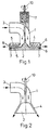
- the shredding and allocation device shown in Fig. 1 consists of a fixed part (1) and a part (2) rotatable about an axis.
- the one from the Conveyor e.g. pumped by a thick matter pump and by large foreign bodies freed sludge enters the shredding and at the inlet opening (3) Allocation device.
- the inlet opening (3) has a nozzle and can Via a flange connection or screw connection (not shown in FIG. 1) with the In Fig. 1 also not shown pressure line between the conveyor and Shredding and allocation device can be connected.
- the sewage sludge is passed through the gap (4) within the comminution and allocation device.
- the shape of the depressions can be chosen so that at the crossovers of edges of the depressions in the fixed and in the rotatable part from these edges approximately right angles are formed.
- a division of the sludge inside the grinder and grinder in areas with larger and smaller cross sections is different Wise possible.
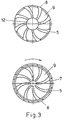
- the depressions run (5) radially in the fixed part shown in the upper half of FIG. 4 outside, while the rotatable part shown in the lower half of FIG. 4, one or more spiral depressions containing the depressions in the fixed Cross the part at an almost right angle.
- the in Fig. 3 shown variant of the device according to the invention are also in the in Fig. 4 shown variant with rotation of the rotatable part of the sludge strand areas with a larger and a smaller cross section along the depressions pushed in the fixed and rotatable part to the outlet openings.
- the depressions in the fixed and the same length in the moving part and the number of depressions in both parts same size.
- the depressions have in the fixed part directly to the outside, i.e. they are as short as possible while walking from the inside out through the spiral depression is much longer in the moving part.
- the center lines of the depressions in the fixed and in the moving part must not, as in the variant shown in Fig. 4, at an angle of cross approximately 90 °, but can also, as shown in Fig. 3, under cross at a much smaller angle. Also at crossing angles other than The sludge strands become 90 ° in areas with larger and in areas with smaller cross section divided, these areas upon rotation of the rotatable Part pushed in the directions marked in Figs. 3 and 4 to the outside become. When the depressions cross at an angle of 90 °. then the areas with larger and smaller cross sections become parallel to The center line of the depressions (5) is conveyed outwards. In the event of a deviation from the Crossing angle by a certain amount x, i.e.
- the sludge leaves the crushing and Allocation device in a plane perpendicular to the axis of rotation (10). It other exit angles are also possible.
- Fig. 2 e.g. one embodiment the device according to the invention is shown schematically, in which the sewage sludge the device along a cone shell at an angle of 30 ° to the axis of rotation (10). By varying the exit angle, the area into which the shredded pieces of sludge are conveyed varies and needs be adapted to the respective application.
- the feed line for the sludge supply may be used with both the gap (4) forming parts, not rigid or only with the fixed Part rigidly connected.
- the speed of the sludge conveyor e.g. a thick matter pump
- Mud flow can be varied.
- the speed of the rotatable Part of the shredding and allocation device can be the size of the generated sludge particles can be varied. The greater the speed of the thick matter pump and the lower the speed of the rotatable part, the larger Sludge particles are generated.
- Crushing and allocation devices represent as mechanically dewatered Sewage sludge, or if no shredding into pieces of equal size is required, simplified variants of the device according to the invention can be used become. If you do without e.g. either on the teeth on the edge of the fixed Part (1) or on the teeth on the edge of the rotatable part (2), then emerge the outlet openings sludge strands with a periodically changing cross-section which no longer breaks up into small pieces due to the teeth that are still present become. The areas of the sludge strand with a smaller cross section form predetermined breaking points, on which the sludge strand with the appropriate consistency e.g. can break apart due to its own weight.
- the shape and size of the areas with larger and smaller cross sections can by changing the shape of the wells to meet different needs be adjusted.
- By changing the ratio of the width of the webs between the wells and the width of the outlet openings can also Ratio of the length of the sections with larger and smaller cross sections of the sludge strands emerging from the outlet openings can be varied.
Landscapes
- Chemical & Material Sciences (AREA)
- Organic Chemistry (AREA)
- Chemical Kinetics & Catalysis (AREA)
- Engineering & Computer Science (AREA)
- Food Science & Technology (AREA)
- Crushing And Pulverization Processes (AREA)
- Treatment Of Sludge (AREA)
- Disintegrating Or Milling (AREA)
- Crushing And Grinding (AREA)
- Feeding, Discharge, Calcimining, Fusing, And Gas-Generation Devices (AREA)
Applications Claiming Priority (2)
| Application Number | Priority Date | Filing Date | Title |
|---|---|---|---|
| DE19813485A DE19813485A1 (de) | 1998-03-26 | 1998-03-26 | Zerkleinerungs- und Zuteilungsvorrichtung für zerstückelbare, pumpbare Stoffe |
| DE19813485 | 1998-03-26 |
Publications (1)
| Publication Number | Publication Date |
|---|---|
| EP0945172A1 true EP0945172A1 (fr) | 1999-09-29 |
Family
ID=7862495
Family Applications (1)
| Application Number | Title | Priority Date | Filing Date |
|---|---|---|---|
| EP99105783A Withdrawn EP0945172A1 (fr) | 1998-03-26 | 1999-03-22 | Dispositif de concassage et répartition de matériaux désintegrables et pompables |
Country Status (11)
| Country | Link |
|---|---|
| US (1) | US6186426B1 (fr) |
| EP (1) | EP0945172A1 (fr) |
| JP (1) | JP2000024486A (fr) |
| KR (1) | KR19990078313A (fr) |
| CN (1) | CN1231944A (fr) |
| AU (1) | AU2138299A (fr) |
| CA (1) | CA2266573A1 (fr) |
| DE (1) | DE19813485A1 (fr) |
| HU (1) | HUP9900700A1 (fr) |
| PL (1) | PL332233A1 (fr) |
| TW (1) | TW464538B (fr) |
Cited By (3)
| Publication number | Priority date | Publication date | Assignee | Title |
|---|---|---|---|---|
| FR2921278A1 (fr) * | 2007-09-24 | 2009-03-27 | Ecole Nationale D Ingenieurs D | Dispositif pour la formation de gouttelettes calibrees |
| DE102017120047A1 (de) | 2017-08-31 | 2019-02-28 | Bma Braunschweigische Maschinenbauanstalt Ag | Schneidvorrichtung, System mit einer Schneidvorrichtung und einer Weiterverarbeitungseinrichtung sowie Verfahren zum Zerkleinern von pastösen Stoffen |
| CN109179523B (zh) * | 2018-09-18 | 2021-04-02 | 鲁鸣 | 一种污水处理用发制品生产污水处理装置 |
Families Citing this family (21)
| Publication number | Priority date | Publication date | Assignee | Title |
|---|---|---|---|---|
| US7121490B2 (en) * | 2004-04-08 | 2006-10-17 | Deseret Laboratories, Inc. | Chopper blade apparatus and method for refining particles |
| US20100313794A1 (en) * | 2007-12-28 | 2010-12-16 | Constantz Brent R | Production of carbonate-containing compositions from material comprising metal silicates |
| US20100239467A1 (en) * | 2008-06-17 | 2010-09-23 | Brent Constantz | Methods and systems for utilizing waste sources of metal oxides |
| KR20100105860A (ko) * | 2007-12-28 | 2010-09-30 | 칼레라 코포레이션 | Co2 분리 방법 |
| US20100144521A1 (en) * | 2008-05-29 | 2010-06-10 | Brent Constantz | Rocks and Aggregate, and Methods of Making and Using the Same |
| WO2010009273A1 (fr) | 2008-07-16 | 2010-01-21 | Calera Corporation | Utilisation du co<sb>2</sb> dans des systèmes électrochimiques |
| US7993500B2 (en) * | 2008-07-16 | 2011-08-09 | Calera Corporation | Gas diffusion anode and CO2 cathode electrolyte system |
| US7815880B2 (en) * | 2008-09-30 | 2010-10-19 | Calera Corporation | Reduced-carbon footprint concrete compositions |
| US7771684B2 (en) | 2008-09-30 | 2010-08-10 | Calera Corporation | CO2-sequestering formed building materials |
| US8869477B2 (en) | 2008-09-30 | 2014-10-28 | Calera Corporation | Formed building materials |
| US9133581B2 (en) | 2008-10-31 | 2015-09-15 | Calera Corporation | Non-cementitious compositions comprising vaterite and methods thereof |
| AU2009287464B2 (en) * | 2008-12-11 | 2010-09-23 | Arelac, Inc. | Processing CO2 utilizing a recirculating solution |
| US20100258035A1 (en) * | 2008-12-24 | 2010-10-14 | Brent Constantz | Compositions and methods using substances containing carbon |
| CA2696075A1 (fr) * | 2009-01-28 | 2010-07-28 | Calera Corporation | Methode electrochimique de production a basse energie d'une solution d'ions bicarbonates |
| US8834688B2 (en) * | 2009-02-10 | 2014-09-16 | Calera Corporation | Low-voltage alkaline production using hydrogen and electrocatalytic electrodes |
| CA2694959A1 (fr) | 2009-03-02 | 2010-09-02 | Calera Corporation | Systemes et methodes de lutte contre de multiples polluants d'ecoulement de gaz |
| US20100229725A1 (en) * | 2009-03-10 | 2010-09-16 | Kasra Farsad | Systems and Methods for Processing CO2 |
| US20110147227A1 (en) * | 2009-07-15 | 2011-06-23 | Gilliam Ryan J | Acid separation by acid retardation on an ion exchange resin in an electrochemical system |
| WO2011066293A1 (fr) * | 2009-11-30 | 2011-06-03 | Calera Corporation | Production d'une solution alcaline à l'aide d'une anode à diffusion gazeuse avec une pression hydrostatique |
| JP6015524B2 (ja) * | 2013-03-29 | 2016-10-26 | Jfeエンジニアリング株式会社 | 粘性物質成形用ノズル装置及び該装置を備えたバンド式乾燥装置 |
| US9815064B2 (en) * | 2013-05-17 | 2017-11-14 | Emerson Electric Co. | Counter top food waste disposer |
Citations (3)
| Publication number | Priority date | Publication date | Assignee | Title |
|---|---|---|---|---|
| US2952448A (en) * | 1957-05-20 | 1960-09-13 | Griffin Cornell Company | Degasifying, blending, milling and homogenizing machinery |
| EP0443772A1 (fr) * | 1990-02-21 | 1991-08-28 | Pfizer Inc. | Appareil pour mélanger et pulvériser une bouillie |
| DE4438105A1 (de) * | 1994-10-25 | 1996-05-02 | Faeser Klaus | Rotationsgranulator |
Family Cites Families (11)
| Publication number | Priority date | Publication date | Assignee | Title |
|---|---|---|---|---|
| US2461720A (en) * | 1944-07-29 | 1949-02-15 | Patterson Foundry & Machine Co | Mixing apparatus |
| CH381059A (de) * | 1960-11-02 | 1964-08-15 | Brogli & Co | Kolloidmühle |
| US3128051A (en) * | 1960-11-07 | 1964-04-07 | Dag Mfg Co | Pump |
| US3915394A (en) * | 1974-03-21 | 1975-10-28 | Bendix Corp | Centrifugal pump including contamination chopping means |
| US3961758A (en) * | 1974-08-23 | 1976-06-08 | Peabody Barnes, Inc. | Centrifugal pump with integral grinder |
| US4145008A (en) * | 1977-08-22 | 1979-03-20 | The Gorman-Rupp Company | Waste material pumping apparatus |
| DE2917814C2 (de) * | 1979-05-03 | 1983-12-08 | J.M. Voith Gmbh, 7920 Heidenheim | Stofflöser zur Herstellung von Papierstoffsuspensionen |
| US4391413A (en) * | 1979-10-16 | 1983-07-05 | B.H.F. (Engineering) Limited | Apparatus for breaking articles |
| US4842479A (en) * | 1981-01-29 | 1989-06-27 | Vaughan Co., Inc. | High head centrifugal slicing slurry pump |
| DE3719441A1 (de) * | 1987-06-11 | 1988-12-22 | Kupczik Guenter | Verfahren zur zerlegung von verklammerten organischen und mineralischen bestandteilen in suspensionen, wie schlaemmen und abwaessern, und vorrichtung zur durchfuehrung des verfahrens |
| DE19527784C2 (de) * | 1995-07-28 | 1998-07-02 | Robert Dipl Ing Vit | Eindickzentrifuge zum Eindicken von Überschußschlamm |
-
1998
- 1998-03-26 DE DE19813485A patent/DE19813485A1/de not_active Withdrawn
-
1999
- 1999-03-19 HU HU9900700A patent/HUP9900700A1/hu unknown
- 1999-03-22 EP EP99105783A patent/EP0945172A1/fr not_active Withdrawn
- 1999-03-22 CA CA002266573A patent/CA2266573A1/fr not_active Abandoned
- 1999-03-24 AU AU21382/99A patent/AU2138299A/en not_active Abandoned
- 1999-03-26 KR KR1019990010559A patent/KR19990078313A/ko not_active Application Discontinuation
- 1999-03-26 JP JP11084717A patent/JP2000024486A/ja active Pending
- 1999-03-26 CN CN99104326A patent/CN1231944A/zh active Pending
- 1999-03-26 PL PL99332233A patent/PL332233A1/xx unknown
- 1999-03-26 US US09/276,748 patent/US6186426B1/en not_active Expired - Fee Related
- 1999-03-29 TW TW088104826A patent/TW464538B/zh active
Patent Citations (3)
| Publication number | Priority date | Publication date | Assignee | Title |
|---|---|---|---|---|
| US2952448A (en) * | 1957-05-20 | 1960-09-13 | Griffin Cornell Company | Degasifying, blending, milling and homogenizing machinery |
| EP0443772A1 (fr) * | 1990-02-21 | 1991-08-28 | Pfizer Inc. | Appareil pour mélanger et pulvériser une bouillie |
| DE4438105A1 (de) * | 1994-10-25 | 1996-05-02 | Faeser Klaus | Rotationsgranulator |
Cited By (4)
| Publication number | Priority date | Publication date | Assignee | Title |
|---|---|---|---|---|
| FR2921278A1 (fr) * | 2007-09-24 | 2009-03-27 | Ecole Nationale D Ingenieurs D | Dispositif pour la formation de gouttelettes calibrees |
| DE102017120047A1 (de) | 2017-08-31 | 2019-02-28 | Bma Braunschweigische Maschinenbauanstalt Ag | Schneidvorrichtung, System mit einer Schneidvorrichtung und einer Weiterverarbeitungseinrichtung sowie Verfahren zum Zerkleinern von pastösen Stoffen |
| DE102017120047B4 (de) | 2017-08-31 | 2021-07-08 | Bma Braunschweigische Maschinenbauanstalt Ag | Schneidvorrichtung, System mit einer Schneidvorrichtung und einer Weiterverarbeitungseinrichtung sowie Verfahren zum Zerkleinern von pastösen Stoffen |
| CN109179523B (zh) * | 2018-09-18 | 2021-04-02 | 鲁鸣 | 一种污水处理用发制品生产污水处理装置 |
Also Published As
| Publication number | Publication date |
|---|---|
| DE19813485A1 (de) | 1999-09-30 |
| HUP9900700A1 (hu) | 2000-06-28 |
| PL332233A1 (en) | 1999-09-27 |
| KR19990078313A (ko) | 1999-10-25 |
| JP2000024486A (ja) | 2000-01-25 |
| AU2138299A (en) | 1999-10-07 |
| HU9900700D0 (en) | 1999-05-28 |
| CN1231944A (zh) | 1999-10-20 |
| TW464538B (en) | 2001-11-21 |
| CA2266573A1 (fr) | 1999-09-26 |
| US6186426B1 (en) | 2001-02-13 |
Similar Documents
| Publication | Publication Date | Title |
|---|---|---|
| EP0945172A1 (fr) | Dispositif de concassage et répartition de matériaux désintegrables et pompables | |
| EP0394233B1 (fr) | Dispositif de preparation de materiaux | |
| DE60031807T2 (de) | Vorrichtung zur Granulierung von Kunststoffen | |
| EP2892856A1 (fr) | Unité d'extrusion et installation de séchage équipée de celle-ci | |
| DE2335385B2 (de) | Verfahren und Vorrichtung zur ölgewinnung aus gereinigten Ölfrüchten und ölsaaten | |
| EP3057751B1 (fr) | Dispositif et procédé de nettoyage de matières plastiques dans le cadre de leur recyclage | |
| DE3043194A1 (de) | Einrichtung zum mechanischen trennen von fluessigkeiten aus fluessigkeitsfeststoffgemischen in einer schneckenpresse | |
| DE2440345A1 (de) | Vorrichtung zum sortieren von abfall | |
| DE1921316A1 (de) | Verfahren und Vorrichtung zum Zerkleinern von Werkstoffstuecken | |
| WO1996032242A1 (fr) | Dispositif de preparation de matieres thermoplastiques | |
| DE2256524A1 (de) | Verfahren und vorrichtung zum zerkleinern von gut in kleine stuecke | |
| DE2453541A1 (de) | Vorrichtung zum zerkleinern von abfall | |
| DE3140624A1 (en) | Dried material pulverizing and discharging device for multistage continuous vacuum drying apparatus | |
| DE2256267A1 (de) | Mit scherwirkung arbeitender zerkleinerer | |
| DE3046384C2 (fr) | ||
| DE592523C (de) | Stoffmuehle zum Nachbehandeln von Aufloeserstoffen und zum Zerkleinern von Holzstoff, Zellstoff u. dgl. | |
| DE3910115C3 (de) | Walzenbrecher | |
| EP2548648B1 (fr) | Broyeur pour le broyage de matière | |
| DE3704725A1 (de) | Zerkleinerungsmaschine, vorzugsweise fuer altreifen | |
| DE10011949C2 (de) | Anlage zur Verarbeitung von umweltbelastenden Abprodukten | |
| EP0736370A2 (fr) | Appareil de déshydratation de matériaux | |
| AT399844B (de) | Filtervorrichtung, insbesondere für thermoplastische kunststoffschmelzen | |
| EP0194996B1 (fr) | Procédé et dispositif pour l'obtention d'une teneur en matière sèche élevée dans la déshydratation de boues | |
| DE3248059A1 (de) | Auspresseinrichtung | |
| EP1609904A1 (fr) | Pulpeur secondaire pour la préparation de pâte |
Legal Events
| Date | Code | Title | Description |
|---|---|---|---|
| PUAI | Public reference made under article 153(3) epc to a published international application that has entered the european phase |
Free format text: ORIGINAL CODE: 0009012 |
|
| AK | Designated contracting states |
Kind code of ref document: A1 Designated state(s): AT BE CH DE DK ES FI FR GB IE IT LI NL SE |
|
| AX | Request for extension of the european patent |
Free format text: AL;LT;LV;MK;RO;SI |
|
| 17P | Request for examination filed |
Effective date: 20000117 |
|
| AKX | Designation fees paid |
Free format text: AT BE CH DE DK ES FI FR GB IE IT LI NL SE |
|
| 17Q | First examination report despatched |
Effective date: 20010813 |
|
| 19U | Interruption of proceedings before grant |
Effective date: 20010319 |
|
| 19W | Proceedings resumed before grant after interruption of proceedings |
Effective date: 20020724 |
|
| STAA | Information on the status of an ep patent application or granted ep patent |
Free format text: STATUS: THE APPLICATION IS DEEMED TO BE WITHDRAWN |
|
| 18D | Application deemed to be withdrawn |
Effective date: 20030124 |