EP0945172A1 - Device for crushing and apportionment of macerable pumpable materials - Google Patents
Device for crushing and apportionment of macerable pumpable materials Download PDFInfo
- Publication number
- EP0945172A1 EP0945172A1 EP99105783A EP99105783A EP0945172A1 EP 0945172 A1 EP0945172 A1 EP 0945172A1 EP 99105783 A EP99105783 A EP 99105783A EP 99105783 A EP99105783 A EP 99105783A EP 0945172 A1 EP0945172 A1 EP 0945172A1
- Authority
- EP
- European Patent Office
- Prior art keywords
- gap
- parts
- forming
- sludge
- edge
- Prior art date
- Legal status (The legal status is an assumption and is not a legal conclusion. Google has not performed a legal analysis and makes no representation as to the accuracy of the status listed.)
- Withdrawn
Links
Images

Classifications
-
- B—PERFORMING OPERATIONS; TRANSPORTING
- B02—CRUSHING, PULVERISING, OR DISINTEGRATING; PREPARATORY TREATMENT OF GRAIN FOR MILLING
- B02C—CRUSHING, PULVERISING, OR DISINTEGRATING IN GENERAL; MILLING GRAIN
- B02C18/00—Disintegrating by knives or other cutting or tearing members which chop material into fragments
-
- B—PERFORMING OPERATIONS; TRANSPORTING
- B01—PHYSICAL OR CHEMICAL PROCESSES OR APPARATUS IN GENERAL
- B01J—CHEMICAL OR PHYSICAL PROCESSES, e.g. CATALYSIS OR COLLOID CHEMISTRY; THEIR RELEVANT APPARATUS
- B01J2/00—Processes or devices for granulating materials, e.g. fertilisers in general; Rendering particulate materials free flowing in general, e.g. making them hydrophobic
- B01J2/02—Processes or devices for granulating materials, e.g. fertilisers in general; Rendering particulate materials free flowing in general, e.g. making them hydrophobic by dividing the liquid material into drops, e.g. by spraying, and solidifying the drops
- B01J2/04—Processes or devices for granulating materials, e.g. fertilisers in general; Rendering particulate materials free flowing in general, e.g. making them hydrophobic by dividing the liquid material into drops, e.g. by spraying, and solidifying the drops in a gaseous medium
-
- B—PERFORMING OPERATIONS; TRANSPORTING
- B01—PHYSICAL OR CHEMICAL PROCESSES OR APPARATUS IN GENERAL
- B01J—CHEMICAL OR PHYSICAL PROCESSES, e.g. CATALYSIS OR COLLOID CHEMISTRY; THEIR RELEVANT APPARATUS
- B01J2/00—Processes or devices for granulating materials, e.g. fertilisers in general; Rendering particulate materials free flowing in general, e.g. making them hydrophobic
- B01J2/14—Processes or devices for granulating materials, e.g. fertilisers in general; Rendering particulate materials free flowing in general, e.g. making them hydrophobic in rotating dishes or pans
Abstract
Description
Die Erfindung betrifft eine Zerkleinerungs- und Zuteilungsvorrichtung für zerstückelbare, pumpbare Stoffe, insbesondere mechanisch entwässerten Klärschlamm Mechanisch entwässerter Klärschlamm enthält Fremdkörper wie metallische Partikel, kleine Steine, Haare und Teile aus Kunststoff, die besondere Anforderungen an Zerkleinerungs- und Zuteilungsvorrichtungen stellen. Derartige Fremdkörper, auch Haare, sind auch in ausgefaultem Klärschlamm enthalten.The invention relates to a comminution and allocation device for choppable, pumpable substances, especially mechanically dewatered sewage sludge Mechanically dewatered sewage sludge contains foreign bodies such as metallic particles, small stones, hair and parts made of plastic, the special requirements place on size reduction and allocation devices. Such foreign bodies, also hair, is also contained in decayed sewage sludge.
Derartige Zerkleinerungs- und Zuteilungsvorrichtungen sind aus den Schritten WO 86/07049 und DE 2356039 bekannt. Nach der Lehre der WO 86/07049 wird ein bis zur pastösen Konsistenz entwässerter Klärschlamm mit Hilfe einer Förderschnecke durch eine Lochmatrize gepreßt. Es entstehen dabei würstchenförmige Partikel, die einem Bandtrockner zugeführt werden. Aus der DE 2356039 ist eine Schlammzuteil- und -dosiervorrichtung für Verbrennungsöfen mit Rostfeuerung bekannt, bei der ein auf einen Wassergehalt von 75-85 % vorentwässerter Schlamm nach dem Austritt aus der Zuteil- und Dosiervorrichtung durch eine mit Messerklingen, Schlagleisten oder Schneiddrahten bestückte Abschneidevorrichtung kleinstückig zerteilt wird.Such comminution and allocation devices are from the steps WO 86/07049 and DE 2356039 known. According to the teaching of WO 86/07049 a to for pasty consistency of dewatered sewage sludge with the help of a screw conveyor pressed through a die. This creates sausage-shaped particles that be fed to a belt dryer. From DE 2356039 a sludge metering and metering device for incinerators with grate firing is known from which is a dewatered sludge with a water content of 75-85% after Exit from the dispensing and dosing device through a knife blade, Blow bars or cutting wires equipped cutting device in small pieces is divided.
Beide Vorrichtungen weisen gravierende Nachteile auf. Bei einer Förderung des Klärschlamms durch eine Lochmatrize, wie es die WO 86/07049 lehrt, besteht die Gefahr der Verstopfung einzelner Löcher aufgrund der im Klärschlamm enthaltenen Fremdkörper wie z.B. Haare, Kunststoffteile oder Holzstückchen. Dies ist auch dann der Fall, wenn der Klärschlamm durch ein Sieb gepreßt und von Fremdkörpern befreit wurde, deren Abmessungen größer als der Durchmesser der Löcher der Lochmatrize sind. Insbesondere Haare werden häufig mit dem einen Ende durch ein anderes Loch der Lochmatrize gedrückt als mit dem anderen Ende. Dies führt zu einer Querschnittsverengung und anschließend zu einer Verstopfung der Löcher mit der Folge, daß derartige Lochmatrizen häufig gereinigt werden müssen. Zur Vermeidung derartiger Verstopfungen ist nach der WO 86/07049 als Preßorgan eine Klappe vorgesehen, deren Fläche der halben Grundfläche der Lochmatrize entspricht und die um eine die Grundfläche der Matrize mittig halbierende Achse schwenkbar ist. Durch eine derartige Klappe kann zwar sichergestellt werden, daß nicht alle Löcher in den durch die Klappe abdeckbaren Matrizenhälften verstopfen. es kann aber nicht sichergestellt werden, daß alle Löcher offen bleiben. Und bei einer der Lehre der DE 2356039 entsprechenden Abschneidevorrichtung besteht die Gefahr, daß die Messerklingen, Schlagleisten oder Schneiddrähte auf harte, im Schlamm enthaltene Steinstücke oder Metallteile auftreffen, was Beschädigungen bzw. einen schnellen Verschleiß der Abschneidevorrichtung zur Folge hat.Both devices have serious disadvantages. If the Sewage sludge through a perforated die, as taught in WO 86/07049, there is Danger of clogging of individual holes due to those contained in the sewage sludge Foreign bodies such as Hair, plastic parts or pieces of wood. This is also then the case when the sewage sludge is pressed through a sieve and freed of foreign bodies whose dimensions were larger than the diameter of the holes in the Perforated matrix. Hair in particular is often cut through with one end another hole in the punch die is pressed than with the other end. this leads to to a cross-sectional narrowing and then to a blockage of the holes with the result that perforated matrices of this type have to be cleaned frequently. For Prevention of such blockages is according to WO 86/07049 as a pressing member a flap is provided, the area of which is half the base area of the die and corresponds to an axis bisecting the base of the die in the middle is pivotable. Such a flap can ensure that do not block all holes in the die halves that can be covered by the flap. however, it cannot be guaranteed that all holes will remain open. And at there is a cutting device corresponding to the teaching of DE 2356039 the danger that the knife blades, blow bars or cutting wires on hard, in Pieces of stone or metal parts containing mud hit them, causing damage or results in rapid wear of the cutting device.
Es ist daher Aufgabe der Erfindung, eine Zerkleinerungs- und Zuteilungsvorrichtung für zerstückelbare, pumpbare Stoffe, insbesonders mechanisch entwässerten Klärschlamm, anzugeben, mit der etwa gleich große Stücke hergestellt und in regelbarer Menge einer nachfolgenden Vorrichtung z.B. einen Trockner zugeführt werden können, wobei die erwähnten Nachteile der bekannten Zerkleinerungs- und Zuteilvorrichtungen nicht auftreten.It is therefore an object of the invention to provide a size reduction and allocation device for dismemberable, pumpable substances, especially mechanically dewatered sewage sludge, specify with which pieces of approximately the same size are manufactured and in controllable Quantity of a subsequent device e.g. fed a dryer can be, the mentioned disadvantages of the known crushing and Allocation devices do not occur.
Die Erfindungsaufgabe wird durch die im Hauptanspruch angegebenen konstruktiven Merkmale der Zerkleinerungs- und Zuteilungsvorrichtung gelöst.The task of the invention is by the constructive specified in the main claim Features of the shredding and allocation device solved.
Im folgenden wird die Zerkleinerung und Zuteilung von mechanisch vorentwässertem Klärschlamm mit Hilfe der erfindungsgemäßen Vorrichtung beschrieben.The following is the crushing and allocation of mechanically pre-dewatered Sewage sludge described using the device according to the invention.
Es zeigen
- Fig. 1
- eine Gesamtdarstellung der Zerkleinerungs- und Zuteilungs vorrichtung,
- Fig. 2
- eine Gesamtdarstellung einer anderen Ausführungsform der Zerkleinerungs- und Zerteilungsvorrichtung,
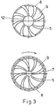
- Fig. 3
- einen Teil der erfindungsgemäßen Vorrichtung zur Verdeutlichung des Transportes und der Zerkleinerung des Klärschlammes,
- Fig. 4
- eine andere Ausführungsform des in Fig. 3 dargestellten Teiles.
- Fig. 1
- an overall view of the shredding and allocation device,
- Fig. 2
- an overall view of another embodiment of the shredding and dividing device,
- Fig. 3
- a part of the device according to the invention for clarifying the transport and comminution of the sewage sludge,
- Fig. 4
- another embodiment of the part shown in Fig. 3.
Ausgefaulter und nichtausgefaulter Klärschlamm werden üblicherweise vor der Durchführung weiterer Behandlungsschritte mit Hilfe von Zentrifugen, Bandfilter-, Kammerfilterpressen oder ähnlichen Vorrichtungen möglichst weitgehend mechanisch entwässert. In der Regel werden je nach Schlammbeschaffenheit und verwendeten Entwässerungsvorrichtungen Trockensubstanzgehalte zwischen ca. 15-30 % erreicht. Digested and non-digested sewage sludge are usually placed in front of the Carrying out further treatment steps with the aid of centrifuges, belt filter, Chamber filter presses or similar devices as much as possible mechanically drained. As a rule, depending on the nature of the sludge and used Drainage devices dry matter contents between approx. 15-30 % reached.
In diesem Bereich ist der Schlamm sowohl förderbar, z.B. mit einer Förderschnecke oder Dickstoffpumpe, als auch zerstückelbar.In this area the sludge is both conveyable, e.g. with a screw conveyor or thick matter pump, as well as dismemberable.
Um Schäden an der erfindungsgemäßen Zerkleinerungs- und Zuteilungsvorrichtung durch größere, im Schlamm enthaltene, harte Fremdstoffe zu vermeiden, ist es zweckmäßig, dafür zu sorgen, daß derartige Fremdstoffe nicht in die erfindungsgemäße Zerkleinerungs- und Zuteilungsvorrichtung gelangen können. Dies ist z.B. dadurch möglich, daß der Schlamm durch ein Sieb entsprechender Maschenweite gepreßt wird, bevor er zur Zerkleinerungs- und Zuteilungsvorrichtung gelangt.To damage the shredding and allocation device according to the invention It is to be avoided by larger, hard foreign substances contained in the sludge expedient to ensure that such foreign substances are not in the invention Shredding and allocation device can get. This is e.g. possible that the sludge through a sieve of appropriate mesh size is pressed before it reaches the shredding and allocation device.
Die in Fig. 1 dargestellte Zerkleinerungs- und Zuteilungsvorrichtung besteht aus einem feststehenden (1) und einem um eine Achse drehbaren Teil (2). Der von der Fördervorrichtung, z.B. einer Dickstoffpumpe geförderte und von großen Fremdkörpern befreite Schlamm tritt an der Eintrittsöffnung (3) in die Zerkleinerungs- und Zuteilungsvorrichtung ein. Die Eintrittsöffnung (3) weist einen Stutzen auf und kann über eine in Fig. 1 nicht dargestellte Flanschverbindung oder Verschraubung mit der in Fig. 1 ebenfalls nicht dargestellten Druckleitung zwischen Fördervorrichtung und Zerkleinerungs- und Zuteilungsvorrichtung verbunden werden. Innerhalb der Zerkleinerungs- und Zuteilungsvorrichtung wird der Klärschlamm durch den Spalt (4) zwischen dem feststehenden (1) und dem drehbaren (2) Teil der Zerkleinerungs- und Zuteilungsvorrichtung hindurchgepreßt. In den, diesem Spalt zugewandten, Flächen des feststehenden und des beweglichen Teiles sind von innen nach außen führende Vertiefungen (5) ausgebildet. Die Breite dieser Vertiefungen kann, wie in Fig. 3 und dem oberen Teil der Fig. 4 dargestellt von innen nach außen zunehmen.The shredding and allocation device shown in Fig. 1 consists of a fixed part (1) and a part (2) rotatable about an axis. The one from the Conveyor, e.g. pumped by a thick matter pump and by large foreign bodies freed sludge enters the shredding and at the inlet opening (3) Allocation device. The inlet opening (3) has a nozzle and can Via a flange connection or screw connection (not shown in FIG. 1) with the In Fig. 1 also not shown pressure line between the conveyor and Shredding and allocation device can be connected. The sewage sludge is passed through the gap (4) within the comminution and allocation device. between the fixed (1) and the rotatable (2) part of the shredding and Allotment device pressed through. In the gap facing this Surfaces of the fixed and the moving part are from the inside to the outside leading recesses (5) trained. The width of these depressions can, as in Fig. 3 and the upper part of Fig. 4 increase from the inside to the outside.
Die Form der Vertiefungen kann dabei so gewählt werden, daß an den Überkreuzungen von Rändern der Vertiefungen im feststehenden und im drehbaren Teil von diesen Rändern annähernd rechte Winkel gebildet werden. Durch eine derartige Formgebung wird erreicht, daß die Schlammstränge bereits im Innern der Zerkleinerungs- und Zuteilungsvorrichtung in Bereiche mit größerem und mit kleinerem Querschnitt aufgeteilt werden, wobei die Bereiche mit größerem Querschnitt bei Drehung des beweglichen Teiles im gekennzeichneten Drehsinn entlang der Vertiefungen im feststehenden Teil in Richtung der Austrittsöffnungen geschoben werden. Bei einer derartigen Konstruktion werden größere Fremdkörper in den Bereichen mit größerem Querschnitt konzentriert. Eine derartige Unterteilung der Schlammstränge in Bereiche mit unterschiedlichen Querschnitten ist auch dann gegeben. wenn sich die Vertiefungen nicht unter einem rechten Winkel kreuzen. In den Fig. 3 und 4 sind verschiedene Formen der Vertiefungen dargestellt.The shape of the depressions can be chosen so that at the crossovers of edges of the depressions in the fixed and in the rotatable part from these edges approximately right angles are formed. By such Shaping is achieved that the sludge strands already inside the Shredding and allocation device in areas with larger and with smaller cross-section can be divided, the areas with larger cross-section when rotating the moving part in the designated direction of rotation of the depressions in the fixed part in the direction of the outlet openings become. With such a construction, larger foreign objects in areas with a larger cross-section. Such a division even then the sludge strands are in areas with different cross sections given. if the depressions do not cross at right angles. In 3 and 4 different shapes of the wells are shown.
Durch die Austrittsöffnungen (8) werden daher Schlammstränge geschoben, die in regelmäßigen Abständen Bereiche mit größerem und Bereiche mit kleinerem Querschnitt aufweisen. Sowohl der feststehende als auch der drehbare Teil sind am Rand in Verlängerung der Stege (9) zwischen den Vertiefungen (5) mit Zähnen (6) besetzt, durch die die austretenden Schlammstränge in den Bereichen mit kleinerem Querschnitt durchtrennt werden. Auf diese Weise werden gleich große Schlammpartikel erzeugt. Da größere harte Fremdkörper in den Bereichen mit größerem Querschnitt konzentriert sind, sind die Zähne (6) vor Beschädigungen durch harte Fremdkörper weitgehend geschützt. Die Gefahr einer derartigen Beschädigung kann noch weiter reduziert werden, wenn die Breite der Zähne (6) etwas geringer ist als die Breite der Stege (9) und wenn in Zähne auf den Stegen um eine kleine Strecke nach hinten zurückgesetzt sind. Wird die Vorderkante der Zähne (6) schräg ausgeführt, so daß die dem Spalt (4) zugewandte Oberkante der Zähne (6) kleiner ist als die mit dem feststehenden bzw. drehbaren Teil verbundene Basis, dann können von den Zähnen nicht durchtrennte Fremdkörper, z.B. Haare zur Oberkante und über die Zähne hinweggleiten. Dadurch wird sichergestellt, daß sich Bestandteile des Schlammes nicht in einer die Funktion der Vorrichtung behindernden Weise an den Zähnen festsetzen können. In Fig. 3 ist der Durchmesser des drehbaren Teiles (untere Hälfte der Fig. 3) etwas größer als der Durchmesser des feststehenden Teiles (obere Hälfte der Fig. 3) und entlang des Randes mit einer Nut (7) versehen, in die die Zähne des feststehenden Teiles eingreifen. Es ist auch möglich, wie in Fig. 4 dargestellt, den Durchmesser des feststehenden Teiles (obere Hälfte der Fig. 4) größer auszuführen als den Durchmesser des drehbaren Teiles (untere Hälfte der Fig. 4) und den feststehenden Teil (2) entlang des Randes mit einer kreisförmigen Nut zu versehen, in die die Zähne (6) des drehbaren Teiles eingreifen. Zur Erhöhung der Schneidwirkung können die Vorderkanten der Zähne angeschliffen sein. Eine Nut (7) ist nicht unbedingt erforderlich, sie erleichtert jedoch die Zentrierung des feststehenden und des beweglichen Teiles, d.h. die Rotationsachse (10) des beweglichen Teiles (2) ist gleichzeitig Symmetrieachse des unteren Teiles des feststehenden Teiles (1).Sludge strands are therefore pushed through the outlet openings (8) Periodic areas of larger and smaller areas Have cross-section. Both the fixed and the rotating part are on Edge in the extension of the webs (9) between the recesses (5) with teeth (6) occupied by the emerging sludge strands in the areas with smaller cross section. In this way, the same size Sludge particles generated. Because having larger hard foreign bodies in the areas larger cross-section are concentrated, the teeth (6) from damage largely protected by hard foreign bodies. The risk of such damage can be reduced even further if the width of the teeth (6) is slightly less than the width of the webs (9) and if in teeth on the webs are set back a small distance. If the front edge of the Teeth (6) run obliquely, so that the gap (4) facing the upper edge of the Teeth (6) is smaller than that connected to the fixed or rotatable part Base, then foreign objects not severed from the teeth, e.g. hair slide to the top edge and over the teeth. This ensures that components of the sludge do not interfere with the function of the device Can fix on the teeth. 3 is the diameter of the rotatable part (lower half of Fig. 3) slightly larger than the diameter of the fixed part (upper half of Fig. 3) and along the edge with a groove (7) into which the teeth of the fixed part engage. It is also possible, as shown in Fig. 4, the diameter of the fixed part (upper half of Fig. 4) larger than the diameter of the rotatable Part (lower half of Fig. 4) and the fixed part (2) along the edge to be provided with a circular groove into which the teeth (6) of the rotatable part intervention. The front edges of the teeth can be used to increase the cutting effect be sanded. A groove (7) is not absolutely necessary, it makes it easier however, the centering of the fixed and the moving part, i.e. the The axis of rotation (10) of the movable part (2) is also the axis of symmetry of the lower part of the fixed part (1).
Bei Stoffen, die zum Verkleben und Verklumpen neigen, ist es von Vorteil, wie in den Fig. 3 und 4 dargestellt, die Breite der Stege (9) größer auszuführen als die Breite der Vertiefungen (5), so daß auch die Breite der auf den Rand der Stege (9) sitzenden Zähne (6) größer sein kann als die Breite der Austrittsöffnungen (8). Sind nämlich die Zähne (6) breiter als die Austrittsöffnungen (8), so vergeht eine gewisse Zeit nach Abtrennung der Schlammpartikel bis die Schlammstränge wieder aus den Austrittsöffnungen (8) austreten können. Dadurch wird die Gefahr reduziert, daß nacheinander abgetrennte Schlammpartikel miteinander verkleben und verklumpen.For substances that tend to stick and clump together, it is an advantage, as in 3 and 4 shown to make the width of the webs (9) larger than that Width of the recesses (5), so that the width of the on the edge of the webs (9) seated teeth (6) can be larger than the width of the outlet openings (8). are namely the teeth (6) wider than the outlet openings (8), so a certain passes Time after separation of the sludge particles until the sludge strands come out of the Exit openings (8) can exit. This reduces the risk that glue the separated sludge particles together and clump together.
Eine Aufteilung des Schlammes im Innern der Zerkleinerungs- und Zuteilungsvorrichtung in Bereiche mit größeren und kleineren Querschnitten ist auf verschiedene Weisen möglich. Bei dem in Fig. 4 dargestellten Beispiel verlaufen die Vertiefungen (5) im feststehenden, in der oberen Hälfte der Fig. 4 dargestellten Teil radial nach außen, während der drehbare , in der unteren Hälfte der Fig. 4 dargestellte Teil, eine oder mehrere spiralförmige Vertiefungen enthält, die die Vertiefungen im feststehenden Teil unter einem annähernd rechten Winkel kreuzen. Wie bei der in Fig. 3 dargestellten Variante der erfindungsgemäßen Vorrichtung werden auch bei der in Fig. 4 dargestellten Variante bei Drehung des drehbaren Teiles die Schlammstrangbereiche mit größerem und mit kleinerem Querschnitt entlang den Vertiefungen im feststehenden und im drehbaren Teil zu den Austrittsöffnungen geschoben.A division of the sludge inside the grinder and grinder in areas with larger and smaller cross sections is different Wise possible. In the example shown in FIG. 4, the depressions run (5) radially in the fixed part shown in the upper half of FIG. 4 outside, while the rotatable part shown in the lower half of FIG. 4, one or more spiral depressions containing the depressions in the fixed Cross the part at an almost right angle. As with the in Fig. 3 shown variant of the device according to the invention are also in the in Fig. 4 shown variant with rotation of the rotatable part of the sludge strand areas with a larger and a smaller cross section along the depressions pushed in the fixed and rotatable part to the outlet openings.
Bei der in Fig. 3 dargestellten Variante sind die Vertiefungen im feststehenden und im beweglichen Teil gleich lang und die Anzahl der Vertiefungen ist in beiden Teilen gleich groß. Bei der in Fig. 4 dargestellten Variante weisen dagegen die Vertiefungen im feststehenden Teil direkt nach außen, d.h. sie sind so kurz wie möglich, während der Weg von innen nach außen durch die spiralförmige Vertiefung im beweglichen Teil viel länger ist. Durch eine derartige Anordnung kann berücksichtigt werden, daß der Transport des Schlammes nach außen in den Vertiefungen des drehbaren Teiles durch die Fliehkraft unterstützt wird. Eine weitere Möglichkeit, die Vertiefungen im feststehenden Teil so kurz wie möglich auszuführen und damit den Reibungswiderstand und die Gefahr einer Verstopfung zu reduzieren, ist durch eine Vergrößerung der zentralen Öffnung (12) realisierbar.In the variant shown in Fig. 3, the depressions in the fixed and the same length in the moving part and the number of depressions in both parts same size. In contrast, in the variant shown in FIG. 4, the depressions have in the fixed part directly to the outside, i.e. they are as short as possible while walking from the inside out through the spiral depression is much longer in the moving part. With such an arrangement be taken into account that the transport of the sludge to the outside in the wells of the rotatable part is supported by the centrifugal force. Another Possibility to make the recesses in the fixed part as short as possible and thus the frictional resistance and the risk of constipation reduce, can be realized by enlarging the central opening (12).
Die Mittellinien der Vertiefungen im feststehenden und im beweglichen Teil müssen sich nicht, wie bei der in Fig. 4 dargestellten Variante, unter einem Winkel von annähernd 90° kreuzen, sondern können sich auch, wie in Fig. 3 dargestellt, unter einem erheblich kleineren Winkel kreuzen. Auch bei anderen Kreuzungswinkeln als 90° werden die Schlammstränge in Bereiche mit größerem und in Bereiche mit kleinerem Querschnitt unterteilt, wobei diese Bereiche bei Drehung des drehbaren Teiles in den in den Fig. 3 und 4 gekennzeichneten Richtungen nach außen geschoben werden. Wenn sich die Vertiefungen unter einem Winkel von 90° kreuzen. dann werden die Bereiche mit größerem und kleineren Querschnitt parallel zur Mittellinie der Vertiefungen (5) nach außen gefördert. Bei einer Abweichung des Kreuzungswinkels um einen bestimmten Betrag x, d.h. bei einem Kreuzungswinkel von 90°-x werden die Schlammbereiche mit größerem und kleinerem Querschnitt nicht mehr parallel sondern unter dem Winkel x zur Mittellinie der Vertiefungen (5) nach außen gefördert. Dadurch erhöht sich zwar der Reibungswiderstand, andererseits kann bei einem Verzicht auf einen Kreuzungswinkel von annähernd 90° eine größere Anzahl von Vertiefungen im drehbaren und im feststehenden Teil eingearbeitet werden.The center lines of the depressions in the fixed and in the moving part must not, as in the variant shown in Fig. 4, at an angle of cross approximately 90 °, but can also, as shown in Fig. 3, under cross at a much smaller angle. Also at crossing angles other than The sludge strands become 90 ° in areas with larger and in areas with smaller cross section divided, these areas upon rotation of the rotatable Part pushed in the directions marked in Figs. 3 and 4 to the outside become. When the depressions cross at an angle of 90 °. then the areas with larger and smaller cross sections become parallel to The center line of the depressions (5) is conveyed outwards. In the event of a deviation from the Crossing angle by a certain amount x, i.e. at a crossing angle The sludge areas with larger and smaller cross-sections become 90 ° -x no longer parallel but at an angle x to the center line of the depressions (5) promoted to the outside. This increases the frictional resistance, on the other hand, if a crossing angle of approx 90 ° a larger number of depressions in the rotatable and in the fixed part be incorporated.
Bei der in Fig. 1 dargestellten Vorrichtung verläßt der Schlamm die Zerkleinerungs- und Zuteilvorrichtung in einer senkrecht zur Drehachse (10) stehenden Ebene. Es sind auch andere Austrittswinkel möglich. In Fig. 2 ist z.B. eine Ausführungsform der erfindungsgemäßen Vorrichtung schematisch dargestellt, bei der der Klärschlamm die Vorrichtung entlang eines Kegelmantels unter einem Winkel von 30° zur Drehachse (10) verläßt. Durch Variation des Austrittswinkels kann das Gebiet, in das die zerkleinerten Schlammstücke gefördert werden, variiert und den Bedürfnissen des jeweiligen Anwendungsfalles angepaßt werden.In the device shown in Fig. 1, the sludge leaves the crushing and Allocation device in a plane perpendicular to the axis of rotation (10). It other exit angles are also possible. In Fig. 2 e.g. one embodiment the device according to the invention is shown schematically, in which the sewage sludge the device along a cone shell at an angle of 30 ° to the axis of rotation (10). By varying the exit angle, the area into which the shredded pieces of sludge are conveyed varies and needs be adapted to the respective application.
In Fig. 1 und 2 sind bevorzugte Ausführungsformen der erfindungsgemäßen Vorrichtung dargestellt. Weitere Varianten sind möglich. Z.B. ist es nicht erforderlich, die Antriebswelle durch die Zuleitung für die Schlammzuführung zu führen; der drehbare Teil könnte auch von unten angetrieben werden.1 and 2 are preferred embodiments of the device according to the invention shown. Other variants are possible. E.g. it is not necessary Guide the drive shaft through the sludge feed line; of the rotatable part could also be driven from below.
Außerdem ist es möglich, beide den Spalt (4) bildenden Teile in Rotation zu versetzen oder den in den Fig. 1 und 2 drehbar dargestellten Teil zu fixieren und statt dessen den in den Fig. 1 und 2 feststehend dargestellten Teil in Rotation zu versetzen. In diesen Fällen darf die Zuleitung für die Schlammzuführung mit beiden, den Spalt (4) bildenden Teilen, nicht starr bzw. nur mit dem jeweils feststehenden Teil starr verbunden sein.It is also possible to set both parts of the gap (4) in rotation or to fix the part shown in FIGS. 1 and 2 rotatably and instead to set the part shown in FIGS. 1 and 2 in rotation. In these cases, the feed line for the sludge supply may be used with both the gap (4) forming parts, not rigid or only with the fixed Part rigidly connected.
Durch Veränderung der Drehzahl der Schlammfördereinrichtung, z.B. einer Dickstoffpumpe, kann der durch die Zerkleinerungs- und Zerteilungsvorrichtung geförderte Schlammstrom variiert werden. Durch Veränderung der Drehzahl des drehbaren Teiles der Zerkleinerungs- und Zuteilungsvorrichtung kann die Größe der erzeugten Schlammpartikel variiert werden. Je größer die Drehzahl der Dickstoffpumpe und je kleiner die Drehzahl des drehbaren Teiles sind, um so größere Schlammpartikel werden erzeugt.By changing the speed of the sludge conveyor, e.g. a thick matter pump, can the conveyed by the shredding and shredding device Mud flow can be varied. By changing the speed of the rotatable Part of the shredding and allocation device can be the size of the generated sludge particles can be varied. The greater the speed of the thick matter pump and the lower the speed of the rotatable part, the larger Sludge particles are generated.
Falls Stoffe zerkleinert und zugeteilt werden sollen, die geringere Ansprüche an Zerkleinerungs- und Zuteilungsvorrichtungen stellen als mechanisch entwässerter Klärschlamm, oder falls keine Zerkleinerung in gleich große Stücke verlangt wird, können vereinfachte Varianten der erfindungsgemäßen Vorrichtung eingesetzt werden. Verzichtet man z.B. entweder auf die Zähne am Rand des feststehenden Teiles (1) oder auf die Zähne am Rand des drehbaren Teiles (2), dann treten aus den Austrittsöffnungen Schlammstränge mit periodisch wechselndem Querschnitt aus, die nicht mehr durch die noch vorhandenen Zähne in kleine Stücke zerteilt werden. Die Bereiche des Schlammstranges mit kleinerem Querschnitt bilden Sollbruchstellen, an denen der Schlammstrang bei entsprechender Konsistenz z.B. aufgrund des eigenen Gewichts auseinander brechen kann.If substances are to be crushed and allocated, the lower requirements apply Crushing and allocation devices represent as mechanically dewatered Sewage sludge, or if no shredding into pieces of equal size is required, simplified variants of the device according to the invention can be used become. If you do without e.g. either on the teeth on the edge of the fixed Part (1) or on the teeth on the edge of the rotatable part (2), then emerge the outlet openings sludge strands with a periodically changing cross-section which no longer breaks up into small pieces due to the teeth that are still present become. The areas of the sludge strand with a smaller cross section form predetermined breaking points, on which the sludge strand with the appropriate consistency e.g. can break apart due to its own weight.
Verzichtet man im feststehenden Teil auf Vertiefungen und bildet den drehbaren Teil ohne Zähne aus oder verzichtet man umgekehrt auf Vertiefungen im drehbaren Teil und bildet den feststehenden Teil ohne Zähne aus, dann treten aus den Austrittsöffnungen Stränge mit gleichbleibendem Querschnitt aus, die von den Zähnen in gleich große Stücke zerteilt werden, wobei die Größe der erzeugten Stücke durch Veränderung der Drehzahl des drehbaren Teiles variiert werden kann. Eine Veränderung der Stückgröße ist außerdem durch Variation der Drehzahl der Dickstoffpumpe möglich.If there are no recesses in the fixed part and the rotatable part is formed Part without teeth or vice versa without recesses in the rotatable Part and forms the fixed part without teeth, then emerge from the outlet openings Strands of constant cross-section made by the teeth be divided into pieces of equal size, the size of the pieces produced by Changing the speed of the rotatable part can be varied. A change the piece size is also by varying the speed of the thick matter pump possible.
Die Erzeugung gleich großer Schlammpartikel wird in einer Reihe verschiedener Anwendungsfälle verlangt, z.B. wenn der getrocknete Schlamm verbrannt oder als Düngemittel ausgebracht werden soll. Bereits bei der Trocknung ist die Zerkleinerung in gleich große Stücke meist von Vorteil, da bei fast allen Trocknungsverfahren größere Stücke längere Trocknungszeiten erfordern. In Anwendungsfällen, in denen der getrocknete Schlamm vermahlen wird, z.B. um ihn als Zuschlagstoff zu nutzen, ist die Erzeugung gleich großer Partikel dagegen von geringer Bedeutung.The production of equally large sludge particles is done in a number of different ways Required use cases, e.g. if the dried mud burned or as Fertilizer to be applied. The shredding is already during drying into pieces of the same size is usually an advantage, as it is used in almost all drying processes larger pieces require longer drying times. In use cases, in which the dried sludge is ground, e.g. around it as an aggregate however, the generation of particles of the same size is of little importance.
Durch die Bewegung des drehbaren Teiles gegen den feststehenden Teil und durch die Ausbildung von Schlammbereichen mit größeren und kleineren Querschnitten wird ein Verstopfen der Zerkleinerungs- und Zuteilungsvorrichtung wirksam verhindert und die Gefahr von Beschädigungen der Zähne (6) durch im Schlamm enthaltene Fremdkörper reduziert.By moving the rotatable part against the fixed part and through the formation of sludge areas with larger and smaller cross sections clogging of the crushing and dispensing device is effectively prevented and the risk of damage to the teeth (6) from in the mud foreign bodies contained are reduced.
Form und Größe der Bereiche mit größerem und kleinerem Querschnitt können durch Veränderung der Form der Vertiefungen unterschiedlichen Bedürfnissen angepaßt werden. Durch Veränderung des Verhältnisses der Breite der Stege zwischen den Vertiefungen und der Breite der Austrittsöffnungen kann ferner das Verhältnis der Länge der Abschnitte mit größerem und kleinerem Querschnitt der aus den Austrittsöffnungen austretenden Schlammstränge variiert werden.The shape and size of the areas with larger and smaller cross sections can by changing the shape of the wells to meet different needs be adjusted. By changing the ratio of the width of the webs between the wells and the width of the outlet openings can also Ratio of the length of the sections with larger and smaller cross sections of the sludge strands emerging from the outlet openings can be varied.
Trotz aller Vorsichtsmaßnahmen muß damit gerechnet werden, daß aufgrund von Störungen oder Fehlern Verstopfungen auftreten oder zu große, harte Fremdkörper in die Zerkleinerungs- und Zuteilungsvorrichtung gelangen. Um in diesen Fällen Betriebsausfälle zu vermeiden und Beschädigungen der erfindungsgemäßen Vorrichtung zu verhindern, kann der bewegliche Teil, wie in Fig. 1 dargestellt, z.B. durch eine Feder (11) in seiner normalen Position gehalten werden. Verstopfungen treten meist im Bereich der engsten Stellen, d.h. im Spalt zwischen dem drehbaren und dem feststehenden Teil auf. Im Falle einer solchen Verstopfung steigt der Druck auf den drehbaren Teil, die Feder (11) wird zusammengedrückt, der drehbare Teil verschiebt sich entlang der Drehachse (10) und der Spalt weitet sich. Dadurch wird die Verstopfung beseitigt und zu große Fremdkörper können aus der erfindungsgemäßen Vorrichtung entfernt werden, ohne daß Betriebsunterbrechungen oder Beschädigungen in Kauf genommen werden müssen.Despite all precautionary measures, it must be expected that due to Malfunctions or errors Blockages occur or too large, hard foreign bodies get into the shredding and allocation device. To in these cases To avoid operational failures and damage to the device according to the invention to prevent the moving part, as shown in Fig. 1, e.g. are held in its normal position by a spring (11). Constipation mostly occur in the area of the narrowest points, i.e. in the gap between the rotatable and the fixed part. In the event of such constipation, the Pressure on the rotatable part, the spring (11) is compressed, the rotatable Part moves along the axis of rotation (10) and the gap widens. Thereby the blockage is removed and oversized objects can be removed from the invention Device can be removed without interrupting operations or damage must be accepted.
Claims (10)
Applications Claiming Priority (2)
| Application Number | Priority Date | Filing Date | Title |
|---|---|---|---|
| DE19813485 | 1998-03-26 | ||
| DE19813485A DE19813485A1 (en) | 1998-03-26 | 1998-03-26 | Shredding and allocation device for choppable, pumpable substances |
Publications (1)
| Publication Number | Publication Date |
|---|---|
| EP0945172A1 true EP0945172A1 (en) | 1999-09-29 |
Family
ID=7862495
Family Applications (1)
| Application Number | Title | Priority Date | Filing Date |
|---|---|---|---|
| EP99105783A Withdrawn EP0945172A1 (en) | 1998-03-26 | 1999-03-22 | Device for crushing and apportionment of macerable pumpable materials |
Country Status (11)
| Country | Link |
|---|---|
| US (1) | US6186426B1 (en) |
| EP (1) | EP0945172A1 (en) |
| JP (1) | JP2000024486A (en) |
| KR (1) | KR19990078313A (en) |
| CN (1) | CN1231944A (en) |
| AU (1) | AU2138299A (en) |
| CA (1) | CA2266573A1 (en) |
| DE (1) | DE19813485A1 (en) |
| HU (1) | HUP9900700A1 (en) |
| PL (1) | PL332233A1 (en) |
| TW (1) | TW464538B (en) |
Cited By (3)
| Publication number | Priority date | Publication date | Assignee | Title |
|---|---|---|---|---|
| FR2921278A1 (en) * | 2007-09-24 | 2009-03-27 | Ecole Nationale D Ingenieurs D | Device for producing calibrated droplets, e.g. for micro-encapsulating medicines and other materials, comprises a rotating liquid receiver from which droplets are expelled by centrifugal force at the periphery |
| DE102017120047A1 (en) | 2017-08-31 | 2019-02-28 | Bma Braunschweigische Maschinenbauanstalt Ag | Cutting device, system with a cutting device and a further processing device and method for comminuting pasty substances |
| CN109179523B (en) * | 2018-09-18 | 2021-04-02 | 鲁鸣 | Sewage treatment is with sending out goods production sewage treatment plant |
Families Citing this family (21)
| Publication number | Priority date | Publication date | Assignee | Title |
|---|---|---|---|---|
| US7121490B2 (en) * | 2004-04-08 | 2006-10-17 | Deseret Laboratories, Inc. | Chopper blade apparatus and method for refining particles |
| JP2012513944A (en) * | 2007-12-28 | 2012-06-21 | カレラ コーポレイション | How to capture CO2 |
| US20100313794A1 (en) * | 2007-12-28 | 2010-12-16 | Constantz Brent R | Production of carbonate-containing compositions from material comprising metal silicates |
| US20100239467A1 (en) | 2008-06-17 | 2010-09-23 | Brent Constantz | Methods and systems for utilizing waste sources of metal oxides |
| US20100144521A1 (en) * | 2008-05-29 | 2010-06-10 | Brent Constantz | Rocks and Aggregate, and Methods of Making and Using the Same |
| US7993500B2 (en) * | 2008-07-16 | 2011-08-09 | Calera Corporation | Gas diffusion anode and CO2 cathode electrolyte system |
| KR20110038691A (en) * | 2008-07-16 | 2011-04-14 | 칼레라 코포레이션 | Co2 utilization in electrochemical systems |
| WO2010039903A1 (en) | 2008-09-30 | 2010-04-08 | Calera Corporation | Co2-sequestering formed building materials |
| US8869477B2 (en) | 2008-09-30 | 2014-10-28 | Calera Corporation | Formed building materials |
| US7815880B2 (en) * | 2008-09-30 | 2010-10-19 | Calera Corporation | Reduced-carbon footprint concrete compositions |
| US9133581B2 (en) | 2008-10-31 | 2015-09-15 | Calera Corporation | Non-cementitious compositions comprising vaterite and methods thereof |
| CA2694971C (en) * | 2008-12-11 | 2012-03-20 | Calera Corporation | Processing co2 utilizing a recirculating solution |
| US20100258035A1 (en) * | 2008-12-24 | 2010-10-14 | Brent Constantz | Compositions and methods using substances containing carbon |
| CA2696075A1 (en) * | 2009-01-28 | 2010-07-28 | Calera Corporation | Low-energy electrochemical bicarbonate ion solution |
| WO2010093716A1 (en) | 2009-02-10 | 2010-08-19 | Calera Corporation | Low-voltage alkaline production using hydrogen and electrocatlytic electrodes |
| CA2694959A1 (en) * | 2009-03-02 | 2010-09-02 | Calera Corporation | Gas stream multi-pollutants control systems and methods |
| WO2010104989A1 (en) * | 2009-03-10 | 2010-09-16 | Calera Corporation | Systems and methods for processing co2 |
| US20110147227A1 (en) * | 2009-07-15 | 2011-06-23 | Gilliam Ryan J | Acid separation by acid retardation on an ion exchange resin in an electrochemical system |
| WO2011066293A1 (en) * | 2009-11-30 | 2011-06-03 | Calera Corporation | Alkaline production using a gas diffusion anode with a hydrostatic pressure |
| JP6015524B2 (en) * | 2013-03-29 | 2016-10-26 | Jfeエンジニアリング株式会社 | Nozzle device for forming viscous material and band-type drying device provided with the device |
| US9815064B2 (en) * | 2013-05-17 | 2017-11-14 | Emerson Electric Co. | Counter top food waste disposer |
Citations (3)
| Publication number | Priority date | Publication date | Assignee | Title |
|---|---|---|---|---|
| US2952448A (en) * | 1957-05-20 | 1960-09-13 | Griffin Cornell Company | Degasifying, blending, milling and homogenizing machinery |
| EP0443772A1 (en) * | 1990-02-21 | 1991-08-28 | Pfizer Inc. | Apparatus for mixing and spraying a slurry |
| DE4438105A1 (en) * | 1994-10-25 | 1996-05-02 | Faeser Klaus | Rotary granulator |
Family Cites Families (11)
| Publication number | Priority date | Publication date | Assignee | Title |
|---|---|---|---|---|
| US2461720A (en) * | 1944-07-29 | 1949-02-15 | Patterson Foundry & Machine Co | Mixing apparatus |
| CH381059A (en) * | 1960-11-02 | 1964-08-15 | Brogli & Co | Colloid mill |
| US3128051A (en) * | 1960-11-07 | 1964-04-07 | Dag Mfg Co | Pump |
| US3915394A (en) * | 1974-03-21 | 1975-10-28 | Bendix Corp | Centrifugal pump including contamination chopping means |
| US3961758A (en) * | 1974-08-23 | 1976-06-08 | Peabody Barnes, Inc. | Centrifugal pump with integral grinder |
| US4145008A (en) * | 1977-08-22 | 1979-03-20 | The Gorman-Rupp Company | Waste material pumping apparatus |
| DE2917814C2 (en) * | 1979-05-03 | 1983-12-08 | J.M. Voith Gmbh, 7920 Heidenheim | Pulpers for the production of paper stock suspensions |
| US4391413A (en) * | 1979-10-16 | 1983-07-05 | B.H.F. (Engineering) Limited | Apparatus for breaking articles |
| US4842479A (en) * | 1981-01-29 | 1989-06-27 | Vaughan Co., Inc. | High head centrifugal slicing slurry pump |
| DE3719441A1 (en) * | 1987-06-11 | 1988-12-22 | Kupczik Guenter | Method for breaking down aggregated organic and mineral constituents in suspensions, such as sludges and wastewaters, and apparatus for carrying out the method |
| DE19527784C2 (en) * | 1995-07-28 | 1998-07-02 | Robert Dipl Ing Vit | Thickening centrifuge for thickening excess sludge |
-
1998
- 1998-03-26 DE DE19813485A patent/DE19813485A1/en not_active Withdrawn
-
1999
- 1999-03-19 HU HU9900700A patent/HUP9900700A1/en unknown
- 1999-03-22 CA CA002266573A patent/CA2266573A1/en not_active Abandoned
- 1999-03-22 EP EP99105783A patent/EP0945172A1/en not_active Withdrawn
- 1999-03-24 AU AU21382/99A patent/AU2138299A/en not_active Abandoned
- 1999-03-26 JP JP11084717A patent/JP2000024486A/en active Pending
- 1999-03-26 KR KR1019990010559A patent/KR19990078313A/en not_active Application Discontinuation
- 1999-03-26 PL PL99332233A patent/PL332233A1/en unknown
- 1999-03-26 US US09/276,748 patent/US6186426B1/en not_active Expired - Fee Related
- 1999-03-26 CN CN99104326A patent/CN1231944A/en active Pending
- 1999-03-29 TW TW088104826A patent/TW464538B/en active
Patent Citations (3)
| Publication number | Priority date | Publication date | Assignee | Title |
|---|---|---|---|---|
| US2952448A (en) * | 1957-05-20 | 1960-09-13 | Griffin Cornell Company | Degasifying, blending, milling and homogenizing machinery |
| EP0443772A1 (en) * | 1990-02-21 | 1991-08-28 | Pfizer Inc. | Apparatus for mixing and spraying a slurry |
| DE4438105A1 (en) * | 1994-10-25 | 1996-05-02 | Faeser Klaus | Rotary granulator |
Cited By (4)
| Publication number | Priority date | Publication date | Assignee | Title |
|---|---|---|---|---|
| FR2921278A1 (en) * | 2007-09-24 | 2009-03-27 | Ecole Nationale D Ingenieurs D | Device for producing calibrated droplets, e.g. for micro-encapsulating medicines and other materials, comprises a rotating liquid receiver from which droplets are expelled by centrifugal force at the periphery |
| DE102017120047A1 (en) | 2017-08-31 | 2019-02-28 | Bma Braunschweigische Maschinenbauanstalt Ag | Cutting device, system with a cutting device and a further processing device and method for comminuting pasty substances |
| DE102017120047B4 (en) | 2017-08-31 | 2021-07-08 | Bma Braunschweigische Maschinenbauanstalt Ag | Cutting device, system with a cutting device and a further processing device as well as a method for comminuting pasty substances |
| CN109179523B (en) * | 2018-09-18 | 2021-04-02 | 鲁鸣 | Sewage treatment is with sending out goods production sewage treatment plant |
Also Published As
| Publication number | Publication date |
|---|---|
| PL332233A1 (en) | 1999-09-27 |
| CN1231944A (en) | 1999-10-20 |
| KR19990078313A (en) | 1999-10-25 |
| HU9900700D0 (en) | 1999-05-28 |
| DE19813485A1 (en) | 1999-09-30 |
| AU2138299A (en) | 1999-10-07 |
| TW464538B (en) | 2001-11-21 |
| US6186426B1 (en) | 2001-02-13 |
| HUP9900700A1 (en) | 2000-06-28 |
| JP2000024486A (en) | 2000-01-25 |
| CA2266573A1 (en) | 1999-09-26 |
Similar Documents
| Publication | Publication Date | Title |
|---|---|---|
| EP0945172A1 (en) | Device for crushing and apportionment of macerable pumpable materials | |
| EP0394233B1 (en) | Device for preparation of materials | |
| DE60031807T2 (en) | Device for granulating plastics | |
| EP2892856A1 (en) | Extruder unit and dryer equipped therewith | |
| DE2335385B2 (en) | Method and device for extracting oil from purified oil crops and oil seeds | |
| EP3057751B1 (en) | Device and method for cleaning plastic in the course of plastic recycling | |
| DE3043194A1 (en) | DEVICE FOR MECHANICALLY SEPARATING LIQUIDS FROM LIQUIDS-SOLIDS MIXTURES IN A SCREW PRESS | |
| DE2440345A1 (en) | DEVICE FOR SORTING WASTE | |
| DE1921316A1 (en) | Method and device for comminuting pieces of material | |
| WO1996032242A1 (en) | Device for preparing thermoplastic material | |
| DE2256524A1 (en) | PROCESS AND DEVICE FOR CRUSHING GOOD IN SMALL PIECES | |
| DE2453541A1 (en) | DEVICE FOR CRUSHING WASTE | |
| DE3140624A1 (en) | Dried material pulverizing and discharging device for multistage continuous vacuum drying apparatus | |
| DE2256267A1 (en) | SHEARING CRUSHER | |
| DE3046384C2 (en) | ||
| DE592523C (en) | Pulp mill for the aftertreatment of dissolving substances and for comminuting wood pulp, cellulose and the like. like | |
| DE3910115C3 (en) | Roll crusher | |
| EP2548648B1 (en) | Mill for comminuting of material | |
| DE3704725A1 (en) | Comminution machine, preferably for waste tyres | |
| DE10011949C2 (en) | Plant for the processing of environmentally harmful waste products | |
| EP0736370A2 (en) | Apparatus for dewatering materials | |
| AT399844B (en) | Filter device, in particular for thermoplastic polymer melts | |
| EP0194996B1 (en) | Method and apparatus for obtaining a high content of solid matter in the dewatering of sludges | |
| DE3248059A1 (en) | EXPRESSING DEVICE | |
| EP1609904A1 (en) | Secondary pulper for paper pulp preparation |
Legal Events
| Date | Code | Title | Description |
|---|---|---|---|
| PUAI | Public reference made under article 153(3) epc to a published international application that has entered the european phase |
Free format text: ORIGINAL CODE: 0009012 |
|
| AK | Designated contracting states |
Kind code of ref document: A1 Designated state(s): AT BE CH DE DK ES FI FR GB IE IT LI NL SE |
|
| AX | Request for extension of the european patent |
Free format text: AL;LT;LV;MK;RO;SI |
|
| 17P | Request for examination filed |
Effective date: 20000117 |
|
| AKX | Designation fees paid |
Free format text: AT BE CH DE DK ES FI FR GB IE IT LI NL SE |
|
| 17Q | First examination report despatched |
Effective date: 20010813 |
|
| 19U | Interruption of proceedings before grant |
Effective date: 20010319 |
|
| 19W | Proceedings resumed before grant after interruption of proceedings |
Effective date: 20020724 |
|
| STAA | Information on the status of an ep patent application or granted ep patent |
Free format text: STATUS: THE APPLICATION IS DEEMED TO BE WITHDRAWN |
|
| 18D | Application deemed to be withdrawn |
Effective date: 20030124 |