EP0939290B1 - Ausbildungseinrichtung für ein Kampffahrzeug mit einer schweren Waffe, insbesondere für eine Panzerhaubitze - Google Patents
Ausbildungseinrichtung für ein Kampffahrzeug mit einer schweren Waffe, insbesondere für eine Panzerhaubitze Download PDFInfo
- Publication number
- EP0939290B1 EP0939290B1 EP99103149A EP99103149A EP0939290B1 EP 0939290 B1 EP0939290 B1 EP 0939290B1 EP 99103149 A EP99103149 A EP 99103149A EP 99103149 A EP99103149 A EP 99103149A EP 0939290 B1 EP0939290 B1 EP 0939290B1
- Authority
- EP
- European Patent Office
- Prior art keywords
- magazine
- practice
- training device
- shell
- receiving part
- Prior art date
- Legal status (The legal status is an assumption and is not a legal conclusion. Google has not performed a legal analysis and makes no representation as to the accuracy of the status listed.)
- Expired - Lifetime
Links
- 239000004429 Calibre Substances 0.000 title 1
- 239000006096 absorbing agent Substances 0.000 claims description 5
- 230000035939 shock Effects 0.000 claims description 5
- 230000001154 acute effect Effects 0.000 claims description 2
- 238000013016 damping Methods 0.000 claims description 2
- 235000004443 Ricinus communis Nutrition 0.000 claims 1
- 240000000528 Ricinus communis Species 0.000 claims 1
- 238000006073 displacement reaction Methods 0.000 claims 1
- 230000007246 mechanism Effects 0.000 claims 1
- 230000001953 sensory effect Effects 0.000 claims 1
- 238000000034 method Methods 0.000 description 16
- 238000005303 weighing Methods 0.000 description 3
- 230000004888 barrier function Effects 0.000 description 2
- 239000004020 conductor Substances 0.000 description 2
- 230000001419 dependent effect Effects 0.000 description 1
- 238000011161 development Methods 0.000 description 1
- 230000018109 developmental process Effects 0.000 description 1
- 238000005096 rolling process Methods 0.000 description 1
Images




Classifications
-
- F—MECHANICAL ENGINEERING; LIGHTING; HEATING; WEAPONS; BLASTING
- F42—AMMUNITION; BLASTING
- F42B—EXPLOSIVE CHARGES, e.g. FOR BLASTING, FIREWORKS, AMMUNITION
- F42B8/00—Practice or training ammunition
- F42B8/12—Projectiles or missiles
-
- F—MECHANICAL ENGINEERING; LIGHTING; HEATING; WEAPONS; BLASTING
- F41—WEAPONS
- F41A—FUNCTIONAL FEATURES OR DETAILS COMMON TO BOTH SMALLARMS AND ORDNANCE, e.g. CANNONS; MOUNTINGS FOR SMALLARMS OR ORDNANCE
- F41A33/00—Adaptations for training; Gun simulators
Definitions
- the invention relates to a training device for a combat vehicle with a heavy weapon, in particular for a howitzer howitzer, such as in the Document DE.A.11 87 523 discloses.
- the invention is based on the object, a training device to create that kind, that very much is simply constructed and by means of simulated Operation all operating functions of the main weapon, the ammunition flow with piecing in automatic mode and all substitute operating modes can be practiced. Furthermore is a simulated cadence shooting with a predetermined number of practice rounds of the same series Conditions without weapons return may be possible.
- the training device consists in principle, four interacting with each other Equipment parts, namely a short pipe, the instead of the soul tube of the heavy weapon occurs; one arranged at the outer free end of the short tube Magazine for recording attached training projectiles; Practice floors adapted to the facility but are essentially in weight and dimensions correspond to a real projectile and a projectile removal aid, by means of the attached practice bullets can be removed again from the magazine.
- the inventive Training device is structurally simple is easy to use and can be used with all corresponding to the safety requirements Additional equipment to be equipped.
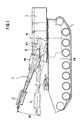
- Fig. 1 shows a tank howitzer with a vehicle trough FW, which has a chain drive L and on a tower T rotatable about a vertical axis VA is stored.
- a weighing body WK rotatably mounted, the one at its inner end a usual Weapon lock WV carries.
- the cradle body WK is instead of the soul tube of the main weapon a short tube 1 used.
- the short tube 1 is designed as a tube pierced inside smooth, stored in the weighing body WK and on the standard weapon lock WV attached.
- Fig. 1 the short tube 1 is shown in two positions, namely once in a position with one Elevations of 20 ° and in dashed lines in the 0 ° position.
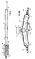
- the magazine 2 has a to a connecting pipe piece 2.4 subsequent recording part 2.1, the is aligned with the axis of the short tube 1.
- a shock absorber 13 in the Front portion of the receiving part is a braking device for the arriving in the receiving part 2.1 Exercise bullets arranged a shock absorber 13 possesses, at the inward one in the longitudinal direction of the receiving part 2.1 sliding catch tray 14th supported.
- This trap 14 is at least partially designed as a half shell and has on her inner edge of a stop 14.1, which is in further manner described below to a stop surface 16.14 can create a training projectile 16.1.
- Farther located in the receiving part a guide rail 7, on which an incoming practice bullet slides so that it is supported and centered.
- magazine shafts 2.2 and 2.3 On both sides of the receiving part 2.1 are magazine shafts 2.2 and 2.3, each for recording of in the embodiment four practice floors are designed. To, as explained below, a good rolling of braked in the receiving part 2.1 To reach practice floors are the magazine shafts 2.2 and 2.3 on the recording 2.1, to the through the axis of the short tube 1 and the elevation axis EL spanned level to a small acute angle arranged inclined.
- the magazine shafts 2.2 and 2.3 have on their outer Ends removal openings, each through a Swing flap 3.1 and 3.2 are closed. each the hinged flaps are outwardly projecting Swivel arms 4.1 and 4.2 connected, in turn connected by a handle bar 5.1 and 5.2 are. In the closed position of the pivoting flaps 3.1 and 3.2 are the pivot arms on locking devices 6.1 or 6.2 lockable. The position the swivel arms 4.1 and 4.2 is by means of adjusting screws 4.11 and 4.21 adjustable.
- the above-mentioned guide rail 7 is supported over Supports 7.2, which the bottom of the receiving part 2.1 pass through, on a support piece 7.3, the attached to the free ends of wings 8.1 and 8.2 is, each at the front and back of the magazine 2 in the area of the first magazine shaft 2.2 in a pivot point 8.3 are hinged and against the Force of tension springs 9.1 and 9.2 swung down are.
- the guide rail 7 in terms of height and angle of inclination adjustable.
- the surface of the guide rail 1 has such Profile 7.1, that, as explained in more detail below, a braked within the receiving part 2.1 Practice floor after lowering the guide rail 7 rolls in the first magazine slot 2.2.
- first magazine shaft 2.2 In the first magazine shaft 2.2 are unlockable locking pawls 11.1 to 11.3 arranged and in the second Magazine shaft 2.3 unlockable locking pawls 12.1 to 12.3 showing the position of the practice rounds in the Define magazine shafts.
- a fallback latch 10 to prevent it from slipping back a braked practice projectile arranged.
- Sensors and light barriers exist, which the Positions of the wings 8.1, 8.2, the swivel arms 4.1, 4.2, the fallback pawl 10, as well as the location of Practice levels in the receiving part 2.1 and the magazine shafts Monitor 2.2 and 2.3.
- Electronic control components and connector for this sensor are above the receiving part 2.1 under a cover 15 arranged.
- a practice floor for use in the above designed device show the Fig. 11 and 12.
- This training projectile is especially for the practice shooting developed with the device and with a few exceptions a replica of a real one Bullet, for example, a Bomblettgeunteres. It has a sleeve 16.1 with an ogive 16.12 at the front end and a removable sleeve bottom 16.13 at the far end, being in the area of Ogive a recess forming a stop surface 16.14 is arranged.
- the Ogive 16.12 is with the Sleeve 16.1 connected via a screw in the Area is the recess, and on the Stop surface 16.14 is a replaceable damping ring 17 attached from plastic.
- the practice floor can with a screwable detonator 16.15 be provided.
- the practice bullets are made using a standard Ammunition transport device from the projectile magazines the tank howitzer at the in Figs. 5A to 10A not exactly shown weapon lock introduced and a usual piecing indicated by A fed.
- the practice projectile 16.1 arrives in a first phase of the piecing process from the piecing A in the Short tube 1 and moves in this direction the magazine 2 on. It becomes as shown in Figs. 6A and 6B in another phase of the piecing process through the inside smooth short tube 1 in the magazine 2 catapults.
- the shock absorber 13 By the shock absorber 13 is the residual energy of the piecing process consumed.
- the receiving part 2.1 is the Exercise projectile 16.1 guided by the guide rail 7.
- the fallback latch 10 prevents slipping back of the practice projectile 16.1 after the deceleration process.
- the movements of the fallback pawl 10 are electronically monitored. Beyond that, the location of the practice projectile by means of a vertically centered arranged light barrier checked.
- FIGS. 8A and 8B it acts the braking of the practice projectile 16.1 whose weight in such a way that the guide rail 7 after is moved downward, with the wings 8.1 and 8.2 against the force of the tension springs 9.1 and 9.2 order pivoted down the pivot point 8.3 around becomes.
- the practice projectile 16.1 is on the ground lowered the magazine.
- the working strokes of the wings 8.1 and 8.2 are monitored by a sensor.
- the surface is 7.1 of the guide rail 7 with such an angle provided that after lowering the practice floor from the receiving part 2.1 in the preferred first Magazine slot 2.2 rolls off.
- Figs. 9A and Fig. 9B the corresponding phase at the third scheduled Practice floor 16.3 presented while the previously scheduled practice bullets 16.1 and 16.2 already in magazine slot 2.2. you will be stored there one after the other. This is for security reasons the closed position of the swing flap 3.1 monitored by sensors.
- the first one is Magazine shaft 2.2 for holding four practice rounds 16.1, 16.2, 16.3 and 16.4.
- the first magazine shaft 2.2 in the direction transverse to Axis of the exercise bullets stored in it so dimensioned that with four practice floors stored in it, as can be seen from FIG. 10B, for the fifth in the receiving part 2.1 incoming training projectile 16.5 a center offset to the opposite second magazine shaft 2.3 occurs and therefore this practice projectile 16.5 in the second magazine shaft 2.3 rolls off.
- the second magazine shaft 2.3 record a total of four practice bullets.
- the pivoting flap 3.2 monitored by sensors.
- the bullet removal aid shown in Fig. 13 has a mounted on wheels 19 frame 18.
- the stability of the frame is additional increased by folding floor supports 25.
- At the front of the frame are a front pair of columns 21 and a rear pair of columns 22 arranged.
- At the four Columns 21 and 22 is a lift truck 23 via guide rollers 23.1 led by means of a two-stage hydraulic telescopic cylinder 25 from a in Fig. 13 dashed lines indicated rest position up in a working position shown in solid lines can be driven.
- the telescopic cylinder 25 is attached via a bracket 25.1 on the frame 18 and is via a line 26 from a hand pump 27 off.
- the lift truck 23 is a receiving tray 24 for receiving arranged by four training floors, the receiving dish 24 has an obliquely sloping forward Base plate and at the rear incident end for the practice bullets is one on bumpers 24.3 mounted catch pan 24.2 arranged.
- a conductor 30 is arranged, which leads to a work platform 20, the surrounded by a railing 20.1 on which an operator BP is indicated.
- the short tube 1 is at an elevation of -2.5 ° lowered and the tower T of the tank howitzer to Page pivoted in a position in which the Short pipe 1 at 90 ° to the longitudinal direction of the vehicle pan FW stands (three o'clock position or nine o'clock position).
- This position offers optimal space to safely approach the bullet removal aid to the corresponding magazine shaft 2.2 or 2.3 of the Magazine 2.
- the bullet removal aid is sent to the magazine 2 approached and by means of the magazine shafts 2.2 and 2.3 arranged as a push rod tensioner trained fastening devices 28, in slots 21.1 on the front pair of columns 21st Attack the projectile removal aid in the scheduled Position determined.
- the lift truck 23 is through Actuate the hand pump 27 from ground level upwards in the working position below the magazine shaft hazards.
- About the conductor 30 enters the operator BP the work platform 20.
- the height of this Work platform is considering the ergonomic Conditions for the operator so designed that when powered-lift truck 23 a safe Remove the practice bullets from the magazine shafts is possible.
- Arretierklinken 11.1 to 11.3 is taken care of; that at Opening the swing flap 3.1 only one practice projectile can fall out of the magazine shaft 2.2. The rest are held in place by means of the locking pawls. Only after reclosing the swing flap 3.1, the locking pawls 11.1 to 11.3 unlocked so that they are still in the magazine shaft 2.2 Exercise bullets can roll and turn a practice floor at the lowest position in the Magazine shaft 2.2 is located, after unlocking and Reopen the swing door 3.1 in the same Can be removed as described above. In this way, by moving up and down the Swing flap 3.1 by means of the handle bar 5.1 all four practice bullets 16.1-16.4 (dashed in Fig. 13) shown) removed from the magazine shaft 2.2 become. Then it does not open by opening one shown hand valve on the hydraulic system the downward movement of the lift truck 23 initiated. In the rest position of the lift truck 23 can then Exercise bullets taken from the receiving tray 24 become.
Landscapes
- Engineering & Computer Science (AREA)
- General Engineering & Computer Science (AREA)
- Aiming, Guidance, Guns With A Light Source, Armor, Camouflage, And Targets (AREA)
- Medical Preparation Storing Or Oral Administration Devices (AREA)
- Warehouses Or Storage Devices (AREA)
- Handcart (AREA)
Description
Claims (21)
- Ausbildungseinrichtung für ein Kampffahrzeug mit einer schweren Waffe, insbesondere für eine Panzerhaubitze, gekennzeichnet durch folgende Merkmale:a) das Seelenrohr der schweren Waffe ist durch ein Kurzrohr (1) ersetzt, das an seinem fahrzeugseitigen Ende die gleichen, an die Aufnahmemittel des Fahrzeugs angepaßten Befestigungsmittel aufweist, wie das Seelenrohr;b) am freien Ende des Kurzrohrs (1) ist ein Magazin (2) zur Aufnahme angesetzter Übungsgeschosse (16.1) angeordnet, in welchem die Übungsgeschosse abgebremst und außerhalb der Rohrseelenachse liegenden Magazinschächten (2.2, 2.3) zugeführt werden;c) es sind Übungsgeschosse (16.1) vorgesehen, die in Gewicht und Abmessungen im wesentlichen einem realen Geschoß entsprechen und im Bereich ihres Vorderteils Mittel (16.14) für den Angriff einer im Magazin (2) angeordneten Bremsvorrichtung (13-14-14.1) aufweisen;d) es ist eine Geschoßentnahmehilfe vorgesehen zum Entnehmen der Übungsgeschosse (16.1) aus dem Magazin (2) mit einem auf Laufrollen (19) laufenden Rahmengestell (18), das eine Arbeitsplattform (20) für das Bedienungspersonal (BP) trägt und an dem ein hydraulisch anhebbarer und absenkbarer Hubwagen (23) zur Aufnahme der aus dem Magazin (2) entnommenen Übungsgeschosse (16.1) und zu ihrer Absenkung auf Bodenniveau angeordnet ist.
- Ausbildungseinrichtung nach Anspruch 1, dadurch gekennzeichnet, daß das Kurzrohr (1) als glatt durchbohrtes Rohr ausgebildet und fahrzeugseitig in der gleichen Weise wie das Seelenrohr im Wiegenkörper (WK) gelagert und im serienmäßigen Waffenverschluß (WV) befestigt ist.
- Ausbildungseinrichtung nach Anspruch 1 oder 2, dadurch gekennzeichnet, daß das Magazin (2) ein fluchtend zur Seelenachse des Kurzrohres (1) angeordnetes und mit diesem verbundenes Aufnahmeteil (2.1) aufweist in und/oder an dessen Vorderteil die Abbremsvorrichtung (13-14) angeordnet ist und zu beiden Seiten des Aufnahmeteils (2.1) Magazinschächte (2.2, 2.3) jeweils zur Aufnahme mehrerer Übungsgeschosse (16.1 bis 16.5) angeordnet sind, wobei Zuführungsmittel (7.1) zur Zuführung der Übungsgeschosse zu den Magazinschächten (2.2, 2.3) vorgesehen sind.
- Ausbildungseinrichtung nach Anspruch 3, dadurch gekennzeichnet, daß die Magazinschächte (2.2, 2.3) am Aufnahmeteil (2.1) zu der durch die Seelenachse des Kurzrohres (1) und die Elevationsachse (EL) aufgespannten Ebene um einen kleinen spitzen Winkel geneigt angeordnet sind.
- Ausbildungseinrichtung nach einem der Ansprüche 1 bis 4, dadurch gekennzeichnet, daß am äußeren Ende jedes Magazinschachts (2.2, 2.3) eine mittels einer Schwenkklappe (3.1, 3.2) verschließbare Entnahmeöffnung angeordnet ist, und die Schwenkklappe (3.1, 3.2) mit nach außen ragenden Schwenkarmen (4.1, 4.2) verbunden ist, die über eine Griffstange (5.1, 5.2) miteinander verbunden sind.
- Ausbildungseinrichtung nach Anspruch 5, dadurch gekennzeichnet, daß die Schwenkarme (4.1, 4.2) in der Schließstellung der Schwenkklappe (3.1, 3.2) über eine Verriegelungsvorrichtung (6.1, 6.2) verriegelbar sind.
- Ausbildungseinrichtung nach Anspruch 3, dadurch gekennzeichnet, daß im Aufnahmeteil (2.1) eine Führungsschiene (7) zur Abstützung des in das Aufnahmeteil einlaufenden und dort abgebremsten Übungsgeschosses (16.1) angeordnet ist, die gegen Federkraft (9.1, 9.2) absenkbar ist und deren Oberfläche ein solches Profil (7.1) besitzt, daß das abgebremste Übungsgeschoß nach dem Absenken der Führungsschiene (7) in einen bevorzugten ersten Magazinschacht (2.2) abrollt.
- Ausbildungseinrichtung nach Anspruch 7, dadurch gekennzeichnet, daß der erste Magazinschacht (2.2) in Richtung quer zur Achse der in ihm gelagerten Übungsgeschosse (16.1 bis 16.4) so dimensioniert ist, daß bei einer vorgegebenen Maximalanzahl von in ihn eingebrachten Übungsgeschossen für das nächste in das Aufnahmeteil (2.1) einlaufende Übungsgeschoß ein Mittenversatz zum gegenüberliegenden zweiten Magazinschacht (2.3) hin auftritt und das Übungsgeschoß (16.5) in diesen zweiten Magazinschacht (2.3) abrollt.
- Ausbildungseinrichtung nach den Ansprüchen 7 oder 8, dadurch gekennzeichnet, daß die Führungsschiene (7) auf den freien Enden zweier Schwingen (8.1, 8.2) gelagert ist, die jeweils an der Vorder- und Rückseite des Magazins (2) im Bereich des ersten Magazinschachts (2.2) angelenkt und gegen die Kraft von Zugfedern (9.1, 9.2) nach unten abschwenkbar sind.
- Ausbildungseinrichtung nach Anspruch 3, dadurch gekennzeichnet, daß am Eintrittsende des Aufnahmeteils (2.1) eine Rückfallklinke (10) zur Verhinderung des Zurückrutschens des abgebremsten Übungsgeschosses (16.1) angeordnet ist.
- Ausbildungseinrichtung nach einem der Ansprüche 1 bis 10, dadurch gekennzeichnet, daß in jedem Magazinschacht (2.2, 2.3) entriegelbare Arretierklinken (11.1 bis 11.3; 12.1 bis 12.3) zur Festlegung der Lage der Übungsgeschosse im Magazinschacht angeordnet sind.
- Ausbildungseinrichtung nach Anspruch 3, dadurch gekennzeichnet, daß die Abbremsvorrichtung einen Stoßdämpfer (13) aufweist, an den sich eine in Längsrichtung des Aufnahmeteils (2.1) verschiebbare Auffangschale (14) abstützt, die an ihrer dem ankommenden Übungsgeschoß (16.1) zugewandten Seite einen sich an einer Anschlagfläche (16.14) am Übungsgeschoß (16.1) abstützenden Anschlag (14.1) aufweist.
- Ausbildungseinrichtung nach einem der Ansprüche 5 bis 12, gekennzeichnet durch die Stellungen der Schwingen (8.1, 8.2) und/oder der Schwenkarme (4.1, 4.2) und/oder der Rückfallklinke (10) und/oder die Lage der Übungsgeschosse (16.1) im Aufnahmeteil (2.2) und/oder den Magazinschächten (2.2, 2.3) überwachende Sensoren.
- Ausbildungseinrichtung nach Anspruch 13, dadurch gekennzeichnet, daß an der Oberseite des Magazins (2) unter einer Abdeckhaube (15) elektronische Steuerbauteile und Verbindungselemente, insbesondere für die Sensorik, angeordnet sind.
- Ausbildungseinrichtung nach einem der Ansprüche 1 bis 14, dadurch gekennzeichnet, daß das Übungsgeschoß eine Hülse (16.1) mit einer Ogive (16.12) am vorderen Ende und einen abnehmbaren Hülsenboden (16.13) aufweist, wobei im Bereich der Ogive (16.12) eine, die Anschlagfläche (16.14) bildende Eindrehung angeordnet ist.
- Ausbildungseinrichtung nach Anspruch 15, dadurch gekennzeichnet, daß die Ogive (16.12) mit der Hülse (16.1) über eine Verschraubung verbunden ist und sich die Eindrehung im Bereich der Verbindungsstelle befindet.
- Ausbildungseinrichtung nach Anspruch 16, dadurch gekennzeichnet, daß auf der Anschlagfläche (16.14) ein auswechselbarer Dämpfungsring (17) aus Kunststoff angeordnet ist.
- Ausbildungseinrichtung nach einem der Ansprüche 15 bis 17, dadurch gekennzeichnet, daß das Übungsgeschoß (16) mit einem einschraubbaren Zünder (16.15) versehen ist.
- Ausbildungseinrichtung nach einem der Ansprüche 1 bis 18, dadurch gekennzeichnet, daß am Rahmengestell (18) der Geschoßentnahmehilfe vier Säulen (21, 22) angeordnet sind, an welchen der mit einer Aufnahmeschale (24) versehene Hubwagen (23) geführt ist und im unteren Teil des Rahmengestells (18) die Hydraulikkomponenten (25, 26, 27) zum Anheben und Absenken des Hubwagens (23) montiert sind.
- Ausbildungseinrichtung nach Anspruch 19, dadurch gekennzeichnet, daß die Aufnahmeschale (24) eine schräg verlaufende Bodenplatte (24.1) aufweist und am Einfallende der Aufnahmeschale (24) für die Übungsgeschosse (16.1) eine über Stoßdämpfer (24.3) gelagerte Auffangwippe (24.2) angeordnet ist.
- Ausbildungseinrichtung nach Anspruch 19 oder 20, dadurch gekennzeichnet, daß an den Magazinschächten (2.2, 2.3) Justier- und Befestigungsvorrichtungen (28) für das Rahmengestell (18) der Entnahmehilfe angeordnet sind, die mit Langlöchern (21.1) ind den beiden vorderen Säulen (21) des Rahmengestells zusammenwirken.
Applications Claiming Priority (2)
| Application Number | Priority Date | Filing Date | Title |
|---|---|---|---|
| DE19807976A DE19807976A1 (de) | 1998-02-25 | 1998-02-25 | Ausbildungseinrichtung für ein Kampffahrzeug mit einer schweren Waffe, insbesondere für eine Panzerhaubitze |
| DE19807976 | 1998-02-25 |
Publications (3)
| Publication Number | Publication Date |
|---|---|
| EP0939290A2 EP0939290A2 (de) | 1999-09-01 |
| EP0939290A3 EP0939290A3 (de) | 2001-01-17 |
| EP0939290B1 true EP0939290B1 (de) | 2003-05-21 |
Family
ID=7858909
Family Applications (1)
| Application Number | Title | Priority Date | Filing Date |
|---|---|---|---|
| EP99103149A Expired - Lifetime EP0939290B1 (de) | 1998-02-25 | 1999-02-18 | Ausbildungseinrichtung für ein Kampffahrzeug mit einer schweren Waffe, insbesondere für eine Panzerhaubitze |
Country Status (5)
| Country | Link |
|---|---|
| US (1) | US6161461A (de) |
| EP (1) | EP0939290B1 (de) |
| DE (2) | DE19807976A1 (de) |
| ES (1) | ES2200419T3 (de) |
| NO (1) | NO317841B1 (de) |
Families Citing this family (3)
| Publication number | Priority date | Publication date | Assignee | Title |
|---|---|---|---|---|
| FR2878950B1 (fr) | 2004-12-02 | 2010-05-07 | Giat Ind Sa | Dispositif de simulation de tir pour armes de gros calibre |
| DE102017107442B4 (de) | 2017-04-06 | 2021-03-18 | Krauss-Maffei Wegmann Gmbh & Co. Kg | Vorrichtung zum Laden einer Rohrwaffe mit Munitionskörpern |
| NL2028658B1 (en) * | 2021-07-08 | 2023-01-16 | Van Halteren Metaal B V | A howitzer training gun |
Family Cites Families (12)
| Publication number | Priority date | Publication date | Assignee | Title |
|---|---|---|---|---|
| FR1085762A (de) * | 1954-06-14 | 1955-02-07 | ||
| US2857812A (en) * | 1956-03-02 | 1958-10-28 | William G Nichols | Gun having artillery training round of ammunition |
| DE1789930U (de) * | 1959-01-26 | 1959-06-04 | Hoffmann Werke J O Hoffmann | Artillerie-exerzier-munition. |
| DE1187523B (de) * | 1963-10-08 | 1965-02-18 | Nico Pyrotechnik | Unterkaliber-Einsatzlauf fuer Manoeverzwecke zum Abschuss von Rauchstrichpatronen, insbesondere aus Panzerabwehrwaffen von der Art der Panzerfaust |
| US3484004A (en) * | 1967-08-02 | 1969-12-16 | Brown Eng Co Inc | Article handling device |
| US4128040A (en) * | 1977-06-02 | 1978-12-05 | Schuetz Robert C | Blank firing adapter |
| FR2492088A1 (fr) * | 1980-10-10 | 1982-04-16 | Thomson Csf | Simulateur d'entrainement au chargement d'un canon |
| DE3625530A1 (de) * | 1986-07-29 | 1988-02-18 | Rheinmetall Gmbh | Einrichtung zur aufnahme von uebungsmunition |
| DE4315829C2 (de) * | 1993-05-12 | 1996-02-08 | Rheinmetall Ind Gmbh | Manöverpatronengerät |
| SE503489C2 (sv) * | 1994-10-13 | 1996-06-24 | Bofors Ab | Ansättningssystem |
| US5773747A (en) * | 1996-05-07 | 1998-06-30 | United Defense, Lp | Two-piece ammunition flick ram |
| US5886280A (en) * | 1997-07-16 | 1999-03-23 | Collins; Brooks L. | Training device for use with combat vehicles |
-
1998
- 1998-02-25 DE DE19807976A patent/DE19807976A1/de not_active Withdrawn
-
1999
- 1999-02-18 US US09/252,342 patent/US6161461A/en not_active Expired - Lifetime
- 1999-02-18 EP EP99103149A patent/EP0939290B1/de not_active Expired - Lifetime
- 1999-02-18 DE DE59905602T patent/DE59905602D1/de not_active Expired - Lifetime
- 1999-02-18 ES ES99103149T patent/ES2200419T3/es not_active Expired - Lifetime
- 1999-02-24 NO NO19990875A patent/NO317841B1/no not_active IP Right Cessation
Also Published As
| Publication number | Publication date |
|---|---|
| ES2200419T3 (es) | 2004-03-01 |
| US6161461A (en) | 2000-12-19 |
| NO990875L (no) | 1999-08-28 |
| DE59905602D1 (de) | 2003-06-26 |
| EP0939290A3 (de) | 2001-01-17 |
| NO990875D0 (no) | 1999-02-24 |
| DE19807976A1 (de) | 1999-08-26 |
| NO317841B1 (no) | 2004-12-20 |
| EP0939290A2 (de) | 1999-09-01 |
Similar Documents
| Publication | Publication Date | Title |
|---|---|---|
| DE2826136C3 (de) | Vorrichtung für den Munitionstransport aus einem gepanzerten Fahrzeug zu einem auf einer Plattform fest angeordneten scheitellafettierten Geschütz | |
| DE2948146C2 (de) | ||
| DE19712641A1 (de) | Übergabeeinrichtung für Rohrschüsse | |
| DE1938681A1 (de) | In einen Panzerturm eingebautes Geschuetz mit umlaufendem Magazin | |
| DE3017323C2 (de) | ||
| DE2433568A1 (de) | Ladevorrichtung fuer die geschosse einer kanone in kampffahrzeugen | |
| DE3612208A1 (de) | Vorrichtung zum laden einer panzerwaffe | |
| DE2546333A1 (de) | Panzermagazin | |
| DE2758693A1 (de) | Kipp- und wechselvorrichtung fuer lastkraftwagen | |
| DE102011050537B3 (de) | Geschütz und militärisches Fahrzeug | |
| EP0906553B1 (de) | Steilfeuergeschütz, insbesondere granatwerfer | |
| DE2257679C3 (de) | Ladehilfe für Panzerkanonen | |
| DE619896C (de) | Munitionszufuehreinrichtung fuer zwei zum gemeinsamen Rahmen der Seitenrichtung verbundene Geschuetze | |
| EP0640805A1 (de) | Geschosszuführungsvorrichtung für eine Panzerhaubitze | |
| DE4115283C2 (de) | Redundante Munitionsflußvorrichtung | |
| EP0939290A2 (de) | Ausbildungseinrichtung für ein Kampffahrzeug mit einer schweren Waffe, insbesondere für eine Panzerhaubitze | |
| DE2546309A1 (de) | Einrichtung mit hochschwenkbarer abdeckung auf einem panzer | |
| DE3930256A1 (de) | Panzerturm | |
| DE3207138C2 (de) | Panzerfahrzeug mit einem im Turm eingebauten Mörser | |
| DE102004063882B4 (de) | Vorrichtung zur Halterung einer Waffenstation | |
| EP0406715B1 (de) | Geschossmagazin für ein Kampffahrzeug | |
| EP2710322B2 (de) | Verfahren zum aufmunitionieren eines munitionslagers sowie munitionslager mit einer vorrichtung zum aufmunitionieren | |
| WO2023138808A1 (de) | Gepanzertes fahrzeug mit notausstiegsluke | |
| DE19519810C2 (de) | Stützbeine für Wechselbehälter | |
| DE1019935B (de) | Ladevorrichtung fuer Waffen gepanzerter Fahrzeuge |
Legal Events
| Date | Code | Title | Description |
|---|---|---|---|
| PUAI | Public reference made under article 153(3) epc to a published international application that has entered the european phase |
Free format text: ORIGINAL CODE: 0009012 |
|
| AK | Designated contracting states |
Kind code of ref document: A2 Designated state(s): DE ES FI FR GB GR IT NL |
|
| AX | Request for extension of the european patent |
Free format text: AL;LT;LV;MK;RO;SI |
|
| PUAL | Search report despatched |
Free format text: ORIGINAL CODE: 0009013 |
|
| AK | Designated contracting states |
Kind code of ref document: A3 Designated state(s): AT BE CH CY DE DK ES FI FR GB GR IE IT LI LU MC NL PT SE |
|
| AX | Request for extension of the european patent |
Free format text: AL;LT;LV;MK;RO;SI |
|
| 17P | Request for examination filed |
Effective date: 20001214 |
|
| AKX | Designation fees paid |
Free format text: DE ES FI FR GB GR IT NL |
|
| GRAH | Despatch of communication of intention to grant a patent |
Free format text: ORIGINAL CODE: EPIDOS IGRA |
|
| GRAH | Despatch of communication of intention to grant a patent |
Free format text: ORIGINAL CODE: EPIDOS IGRA |
|
| GRAA | (expected) grant |
Free format text: ORIGINAL CODE: 0009210 |
|
| AK | Designated contracting states |
Designated state(s): DE ES FI FR GB GR IT NL |
|
| REG | Reference to a national code |
Ref country code: GB Ref legal event code: FG4D Free format text: NOT ENGLISH |
|
| REF | Corresponds to: |
Ref document number: 59905602 Country of ref document: DE Date of ref document: 20030626 Kind code of ref document: P |
|
| REG | Reference to a national code |
Ref country code: GR Ref legal event code: EP Ref document number: 20030402502 Country of ref document: GR |
|
| GBT | Gb: translation of ep patent filed (gb section 77(6)(a)/1977) | ||
| ET | Fr: translation filed | ||
| REG | Reference to a national code |
Ref country code: ES Ref legal event code: FG2A Ref document number: 2200419 Country of ref document: ES Kind code of ref document: T3 |
|
| PLBE | No opposition filed within time limit |
Free format text: ORIGINAL CODE: 0009261 |
|
| STAA | Information on the status of an ep patent application or granted ep patent |
Free format text: STATUS: NO OPPOSITION FILED WITHIN TIME LIMIT |
|
| 26N | No opposition filed |
Effective date: 20040224 |
|
| PGFP | Annual fee paid to national office [announced via postgrant information from national office to epo] |
Ref country code: NL Payment date: 20130218 Year of fee payment: 15 |
|
| REG | Reference to a national code |
Ref country code: NL Ref legal event code: V1 Effective date: 20140901 |
|
| PG25 | Lapsed in a contracting state [announced via postgrant information from national office to epo] |
Ref country code: NL Free format text: LAPSE BECAUSE OF NON-PAYMENT OF DUE FEES Effective date: 20140901 |
|
| PGFP | Annual fee paid to national office [announced via postgrant information from national office to epo] |
Ref country code: FI Payment date: 20150218 Year of fee payment: 17 |
|
| REG | Reference to a national code |
Ref country code: FR Ref legal event code: PLFP Year of fee payment: 18 |
|
| PG25 | Lapsed in a contracting state [announced via postgrant information from national office to epo] |
Ref country code: FI Free format text: LAPSE BECAUSE OF NON-PAYMENT OF DUE FEES Effective date: 20160218 |
|
| REG | Reference to a national code |
Ref country code: FR Ref legal event code: PLFP Year of fee payment: 19 |
|
| PGFP | Annual fee paid to national office [announced via postgrant information from national office to epo] |
Ref country code: FR Payment date: 20170220 Year of fee payment: 19 Ref country code: DE Payment date: 20170228 Year of fee payment: 19 Ref country code: GR Payment date: 20170221 Year of fee payment: 19 |
|
| PGFP | Annual fee paid to national office [announced via postgrant information from national office to epo] |
Ref country code: GB Payment date: 20170221 Year of fee payment: 19 |
|
| PGFP | Annual fee paid to national office [announced via postgrant information from national office to epo] |
Ref country code: ES Payment date: 20170220 Year of fee payment: 19 Ref country code: IT Payment date: 20170217 Year of fee payment: 19 |
|
| REG | Reference to a national code |
Ref country code: DE Ref legal event code: R119 Ref document number: 59905602 Country of ref document: DE |
|
| GBPC | Gb: european patent ceased through non-payment of renewal fee |
Effective date: 20180218 |
|
| PG25 | Lapsed in a contracting state [announced via postgrant information from national office to epo] |
Ref country code: GR Free format text: LAPSE BECAUSE OF NON-PAYMENT OF DUE FEES Effective date: 20180904 |
|
| REG | Reference to a national code |
Ref country code: FR Ref legal event code: ST Effective date: 20181031 |
|
| PG25 | Lapsed in a contracting state [announced via postgrant information from national office to epo] |
Ref country code: DE Free format text: LAPSE BECAUSE OF NON-PAYMENT OF DUE FEES Effective date: 20180901 |
|
| PG25 | Lapsed in a contracting state [announced via postgrant information from national office to epo] |
Ref country code: IT Free format text: LAPSE BECAUSE OF NON-PAYMENT OF DUE FEES Effective date: 20180218 Ref country code: GB Free format text: LAPSE BECAUSE OF NON-PAYMENT OF DUE FEES Effective date: 20180218 Ref country code: FR Free format text: LAPSE BECAUSE OF NON-PAYMENT OF DUE FEES Effective date: 20180228 |
|
| REG | Reference to a national code |
Ref country code: ES Ref legal event code: FD2A Effective date: 20190801 |
|
| PG25 | Lapsed in a contracting state [announced via postgrant information from national office to epo] |
Ref country code: ES Free format text: LAPSE BECAUSE OF NON-PAYMENT OF DUE FEES Effective date: 20180219 |