EP0938914A2 - Ultraschallwellen medizinisches Behandlungsgerät, verwendbar im Gebrauch bei der Führung durch Magnet- Resonanze- Bilddarstellung - Google Patents
Ultraschallwellen medizinisches Behandlungsgerät, verwendbar im Gebrauch bei der Führung durch Magnet- Resonanze- Bilddarstellung Download PDFInfo
- Publication number
- EP0938914A2 EP0938914A2 EP99111088A EP99111088A EP0938914A2 EP 0938914 A2 EP0938914 A2 EP 0938914A2 EP 99111088 A EP99111088 A EP 99111088A EP 99111088 A EP99111088 A EP 99111088A EP 0938914 A2 EP0938914 A2 EP 0938914A2
- Authority
- EP
- European Patent Office
- Prior art keywords
- ultrasonic
- treatment
- ultrasonic wave
- patient
- images
- Prior art date
- Legal status (The legal status is an assumption and is not a legal conclusion. Google has not performed a legal analysis and makes no representation as to the accuracy of the status listed.)
- Granted
Links
Images


Classifications
-
- A—HUMAN NECESSITIES
- A61—MEDICAL OR VETERINARY SCIENCE; HYGIENE
- A61N—ELECTROTHERAPY; MAGNETOTHERAPY; RADIATION THERAPY; ULTRASOUND THERAPY
- A61N7/00—Ultrasound therapy
- A61N7/02—Localised ultrasound hyperthermia
- A61N7/022—Localised ultrasound hyperthermia intracavitary
-
- A—HUMAN NECESSITIES
- A61—MEDICAL OR VETERINARY SCIENCE; HYGIENE
- A61N—ELECTROTHERAPY; MAGNETOTHERAPY; RADIATION THERAPY; ULTRASOUND THERAPY
- A61N7/00—Ultrasound therapy
- A61N7/02—Localised ultrasound hyperthermia
-
- G—PHYSICS
- G01—MEASURING; TESTING
- G01R—MEASURING ELECTRIC VARIABLES; MEASURING MAGNETIC VARIABLES
- G01R33/00—Arrangements or instruments for measuring magnetic variables
- G01R33/20—Arrangements or instruments for measuring magnetic variables involving magnetic resonance
- G01R33/28—Details of apparatus provided for in groups G01R33/44 - G01R33/64
-
- A—HUMAN NECESSITIES
- A61—MEDICAL OR VETERINARY SCIENCE; HYGIENE
- A61B—DIAGNOSIS; SURGERY; IDENTIFICATION
- A61B90/00—Instruments, implements or accessories specially adapted for surgery or diagnosis and not covered by any of the groups A61B1/00 - A61B50/00, e.g. for luxation treatment or for protecting wound edges
- A61B90/36—Image-producing devices or illumination devices not otherwise provided for
- A61B90/37—Surgical systems with images on a monitor during operation
- A61B2090/374—NMR or MRI
Definitions
- the present invention relates to an ultrasonic wave medical treatment apparatus for treating treatment targets such as tumors, calculi, etc. inside a living body by applying intense ultrasonic waves from an outside of the living body or a body cavity of the living body, under the guidance of the magnetic resonance imaging (MRI).
- MRI magnetic resonance imaging
- the researches are also carried out for a treatment method to kill the cancer tissue by the mechanical force of the pulse shaped shock waves having sufficient intensity to destroy the calculi which are irradiated onto the cancer, as disclosed in Hoshi, S. et al.: "High Energy Underwater Shock Wave Treatment on Implanted Urinary Bladder Cancer in Rabbits", Journal of Urology, Vol. 146, pp. 439-443, August, 1991.
- the region behind the pneumatic organs such as the bones and the lung becomes invisible, so that the accurate three-dimensional information cannot be obtained even when the three dimensional ultrasound images are utilized.
- the patient is moved out of the MRI gantry once in order to attach the ultrasonic wave applicator, and then after the positioning of the intense ultrasonic wave focal point with respect to the treatment target portion is made by using the MR images and the ultrasound images, the actual treatment is started.
- the focal point position can be displaced by a slight movement of the patient.
- the probability for the focal point position to be displaced from a desired position becomes large.
- the S/N ratio becomes insufficient for the treatment plan set up, the accurate treatment effect judgement, and the real time treatment monitoring, so that it is necessary to use a surface coil to be placed on the body surface in order to obtain the MR images at a sufficiently high S/N ratio.
- the ultrasonic wave applicator on the body surface near the treatment target portion, it is impossible to place this surface coil on the body surface near the treatment target portion during the ultrasonic wave medical treatment.
- the positioning of the receiving system to image the desired treatment target portion at a high S/N ratio becomes difficult as the surface coil has a relatively large sensitivity fluctuation.
- the ultrasonic transducer is mounted on the catheter and the ultrasonic waves are irradiated from a body cavity, the surface coil cannot be position near the treatment target portion, so that the sufficient MR images of the treatment target portion cannot be obtained.
- the focal point is extremely small, so that in the treatment method such as that for causing the thermal degeneration on the tissues by heating the localized region at a high temperature over 80 °C or that for destroying the tissues mechanically by the shock waves, the displacement of the focal point position can lead to the destroying of the normal tissues, unlike the treatment method such as the hyperthermia which carries out the treatment by utilizing the difference in the thermal sensitivity of the tissues.
- the reflected electric power of the ultrasonic transducer can be increased such that there is a possibility for the electro-acoustic conversion efficiency to be deteriorated.
- the negative pressure at the focal point becomes large as the focal point input power is large, such that the stable cavitations can be generated and grown as the intense ultrasonic waves are applied continuously, and there is a possibility that the sufficient power cannot reach to the intended focal point due to the scattering of the ultrasonic waves by the cavitations.
- an ultrasonic wave medical treatment apparatus comprising: MRI means for taking MR images of a patient in an MRI gantry; and ultrasonic wave treatment means for treating a treatment target portion within the patient by irradiating ultrasonic waves thereon in accordance with the MR images taken by the MRI means, including ultrasonic wave applicator for generating ultrasonic waves focused onto the treatment target portion which is integrally incorporated within a treatment table for carrying the patient into the MRI gantry.
- an ultrasonic wave medical treatment apparatus comprising: MRI means for taking MR images of a patient, including a surface coil for receiving MR signals in taking the MR images; and ultrasonic wave treatment means for treating a treatment target portion within the patient by irradiating ultrasonic waves thereon in accordance with the MR images taken by the MRI means, including ultrasonic wave applicator for generating ultrasonic waves focused onto the treatment target portion having an ultrasonic transducer for generating the ultrasonic waves and a water bag for containing a coupling fluid for leading the ultrasonic waves generated by the ultrasonic transducer to a body surface of the patient by making a contact with the body surface, wherein the surface coil of the MRI means is attached on a surface film of the water bag which makes the contact with the body surface.
- an ultrasonic wave medical treatment apparatus comprising: MRI means for taking MR images of a patient; and ultrasonic wave treatment means for treating a treatment target portion within the patient by irradiating ultrasonic waves thereon in accordance with the MR images taken by the MRI means, including ultrasonic wave applicator for generating ultrasonic waves focused onto the treatment target portion having spike shaped pointers for pointing a focal point of the ultrasonic waves.
- an ultrasonic wave medical treatment apparatus comprising: MRI means for taking MR images of a patient, including a surface coil for receiving MR signals in taking the MR images; and ultrasonic wave treatment means for treating a treatment target portion within the patient by irradiating ultrasonic waves thereon in accordance with the MR images taken by the MRI means, including body cavity probe to be inserted into a body cavity of the patient near the treatment target portion having an ultrasonic transducer for generating ultrasonic waves focused onto the treatment target portion, wherein the surface coil of the MRI means is provided on the body cavity probe.
- an ultrasonic wave medical treatment apparatus comprising: ultrasonic wave applicator for treating a treatment target portion within the patient by irradiating ultrasonic waves focused onto the treatment target portion; and support means for fixedly supporting the ultrasonic wave applicator with respect to the treatment target portion of the patient.
- an ultrasonic wave medical treatment apparatus comprising: ultrasonic wave applicator for treating a treatment target portion within the patient by irradiating ultrasonic waves focused onto the treatment target portion, including an ultrasonic transducer for generating the ultrasonic waves and a water bag for containing a coupling fluid for leading the ultrasonic waves generated by the ultrasonic transducer to a body surface of the patient by making a contact with the body surface; and coupling fluid adjustment means for adjusting a mixing rate of a water and a coupling adjustment agent forming the coupling fluid contained in the water bag according to a temperature of the coupling fluid in the water bag.
- an ultrasonic wave medical treatment apparatus comprising: ultrasonic wave applicator for treating a treatment target portion within the patient by irradiating ultrasonic waves focused onto the treatment target portion, including an ultrasonic transducer for generating the ultrasonic waves; and driving circuit means for driving the ultrasonic transducer to generate the ultrasonic waves; impedance matching circuit means for making an impedance matching between the ultrasonic transducer and the driving circuit means; and control means for controlling one of the driving circuit means and the impedance matching circuit means to make a reflected electric power from the ultrasonic transducer minimum.
- an ultrasonic wave medical treatment apparatus comprising: ultrasonic wave applicator for treating a treatment target portion within the patient by irradiating ultrasonic waves focused onto the treatment target portion, including an ultrasonic transducer for generating the ultrasonic waves; and driving circuit means for driving the ultrasonic transducer to generate the ultrasonic waves; and control means for changing a driving frequency of the driving circuit means while the ultrasonic wave applicator irradiates the ultrasonic waves onto the treatment target portion.
- Fig. 1 the first embodiment of the ultrasonic wave medical treatment apparatus according to the present invention will be described in detail.
- This first embodiment concerns with an overall configuration of the apparatus which is suitable or use in conjunction with the MRI.
- an ultrasonic wave applicator 1 is integrally incorporated by being fixedly attached below a treatment hole 24 formed on the treatment table 22, with its orientation made to be finely adjustable by a mechanical arm 17.
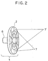
- This ultrasonic wave applicator 1 comprises an ultrasonic transducer 2 for generating intense ultrasonic waves for treatment, a water bag 5 containing a coupling fluid 4 for leading the intense ultrasonic waves to the patient 3 through the treatment hole 24, and an ultrasonic probe 6 for ultrasound imaging provided at a center of the ultrasonic transducer 2, where the ultrasonic transducer 2 has a detailed configuration as shown in Fig. 2 in which a planar disk shaped ultrasonic transducer 2 is divided into a number of channels in radial and circumferential directions while the ultrasonic probe 6 is made to be movable forward and backward as well as rotatable.
- this ultrasonic wave applicator 1 and the mechanical arm 17 are integrally incorporated within the treatment bed 22 as shown in Figs. 3A and 3B such that the ultrasonic wave applicator 1 moves along with the treatment bed 22 when the treatment bed 22 is controlled to carry the patient 3 in and out of an MRI gantry 25.
- an upper opening of the treatment hole 24 is covered by a film 26, and in addition, an RF coil 20 for transmitting RF pulses and receiving MR signals in the MRI is provided at a circumference of the treatment hole 24 in advance.
- the patient 3 is placed on the treatment table 22 such that the tumor 8 to be treated is located above the treatment hole 24, and the focal point 7 of the intense ultrasonic waves from the ultrasonic transducer 2 is adjusted to be focused onto the tumor 8. Then, the ultrasonic transducer 2 is driven by a driving circuit 12 to actually irradiate the intense ultrasonic waves onto the tumor 8 so as to treat the tumor 8 by maintaining the treatment target portion at a high temperature.
- the ultrasonic transducer 2 is made to be a phased array type in which the focal point position, the acoustic field, and the heating region can be controlled without moving the ultrasonic wave applicator 1 itself, by controlling the driving timings of the driving circuit 12 by a phase control circuit 11.
- the driving circuit 12 is divided into a number of channels in correspondence to divided channels of the ultrasonic transducer 2, and each channel is driven by an independent timing signal obtained by appropriately delaying the control signal from a controller 9 at the phase control circuit 11.
- the focal point of the intense ultrasonic waves can be positioned at any desired three dimensional position such as 7 and 7' shown in Fig. 2.
- the detail concerning the shifting of the focal point position by the delayed timing control is disclosed in U.S. Patent No. 4,526,168.
- the size of the treatment hole 24 can be changed by changing the treatment table 22 according to the size and the shape of the treatment target portion.
- the position of the tumor 8 is checked by the ultrasound images taken by the ultrasonic probe 6 attached to the ultrasonic wave applicator 1, and an ultrasonic imaging device 10 supplies the data on the relative position of the tumor 8 and the ultrasonic probe 6 at that point to the controller 9.
- the relative position of the ultrasonic probe 6 and the ultrasonic transducer 2 at that time is determined by a probe position detector 26 and supplied to the controller 9, while the positions of the ultrasonic transducer 2 and the ultrasonic wave applicator 1 with respect to the treatment table 22 at that time is determined by an applicator position detector 15 connected with the mechanical arm 17 and supplied to the controller 9.
- the controller 9 calculates the relative position of the tumor 8 and the ultrasonic transducer 2 from these position data, and determines and memorizes the focal point position set by the phased array.
- This focal point position set by the phased array is supplied from the controller 9 to the ultrasound imaging device 10, such that the ultrasound imaging device 10 can display the state of the tumor 8 at the treatment target portion and the position of the focal point 7 in real time even during the treatment.
- the patient 3 is carried into the MRI gantry 25 in which a static field coil 18 and gradient field coils 19 for the MRI are provided, by moving the treatment table 22 by a table control device 21 under the control by the controller 9.
- a table control device 21 under the control by the controller 9.
- the treatment table 22 can be made of wood or reinforced plastic
- the ultrasonic wave applicator 1 and the mechanical arm 17 can be made of materials such as reinforced plastic and the austenitic cast iron which has nearly the same mechanical property as the usual cast iron while being non-magnetic, except for wirings connecting the ultrasonic transducer 2 and the driving circuit 12 which must be electrically conductive.
- the mechanical arm 17 can be a hydraulic type rather than an electrical type using an electric motor, to further reduce the amount of magnetic material.
- the controller 9 activates the gradient field power source 13 for driving the gradient field coils 19 and the transceiver circuit 14 for driving the RF coil 20 according to the pulse sequence specified from a console 16 such as that of the T2 weighted imaging, so as to obtain and store the three dimensional MR images of the patient 3 in a memory.
- the irradiation of the ultrasonic waves is stopped to observe the progress state of the treatment by the procedure similar to that described above.
- the MR images in a vicinity of the tumor 8 are taken to examine the change in the living body.
- the ultrasonic wave applicator 1 remains to be attached on the patient 3.
- This procedure for making the observation may be incorporated into the treatment plan in advance, such that the MR imaging is carried out at predetermined intervals automatically.
- the controller 9 can call up the history of the treatment condition from the memory and display it as a treatment record on the CRT 23.
- a body cavity probe may be used for the MRI if desired.
- the annular array type or any other suitable type of the ultrasonic transducer may be used if desired.
- the X-ray CT may be used if desired.
- this first embodiment it becomes possible to fix the relative position of the ultrasonic wave applicator and the treatment target portion throughout the treatment, so that the danger for the erroneous irradiation of the intense ultrasonic waves or the unexpected oversight due to the displacement of the focal point from the intended treatment target portion can be reduced. Moreover, the re-positioning after each treatment and treatment effect observation can be avoided, so that the entire treatment period can be shortened considerably.
- Fig. 4 the second embodiment of the ultrasonic wave medical treatment apparatus according to the present invention will be described in detail.
- This second embodiment concerns with the configuration of the ultrasonic wave applicator that can be used in the ultrasonic wave medical treatment apparatus suitable for use in conjunction with the MRI. Consequently, the ultrasonic wave applicator of this second embodiment described below can be used in the overall configuration similar to that of Fig. 1 instead of the ultrasonic wave applicator 1 of the first embodiment described above.
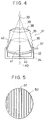
- an ultrasonic wave applicator 31 is formed to have a configuration as shown in Fig. 4, which comprises an ultrasonic transducer 32 having a concave surface for generating intense ultrasonic waves for treatment, a housing 34 made of resin for supporting the ultrasonic transducer 32, a water bag 36 containing a coupling fluid 35 for leading the intense ultrasonic waves to the patient, a water pipe 37 provided on the housing 34 for supplying and withdrawing the coupling fluid 35 to and from the water bag 36, and a surface coil 38 for the MRI attached on a surface film of the water bag 36 on an upper side which makes contact with the body surface of the patient.
- the ultrasonic transducer 32 has the concave surface such that the generated ultrasonic waves will be propagated within a conical passing route 39 indicated by a dashed line and focused on a focal point 33 located at a center of a curvature of the concave surface.
- the surface coil 38 is provided on the upper side of the surface film of the water bag 36 such that the passing route 39 of the ultrasonic waves is contained within its opening. This surface coil 38 can be attached on either an inner side or an outer side of the surface film forming the water bag 36.
- this ultrasonic wave applicator 31 when attached to the patient with the upper side of the surface film of the water bag 36 making a contact with the body surface through ultrasonic jelly, the surface coil 38 can be brought into a tight contact with the body surface as the surface film of the water bag 36 is deformed along the shape of the body surface.
- the ultrasonic transducer 32 is made of a piezoelectric ceramic which is non-magnetic and non-conductive, but on front and back sides of this ultrasonic transducer 32, electrodes for applying driving voltages to the ultrasonic transducer 32 are provided. Consequently, when the radio frequency magnetic field for the MRI is applied on the ultrasonic wave applicator 31, the eddy currents can be induced on these electrodes, and these eddy currents in turn can disturb the magnetic fields for the MRI to cause the degradation of the image quality in the obtained MR images.
- each electrode 50 attached to the ultrasonic transducer 32 of this second embodiment has a number of slits 52 formed thereon as shown in Fig. 5, so as to reduce the electrical conductivity of the electrode 50 with respect to the eddy currents.
- the ultrasonic wave applicator 31 of this second embodiment is further equipped with a needle or rod like spike shaped pointer 41 located along a central axis 40 joining the focal point 33 and a center of the concave surface of the ultrasonic transducer 32, and a plurality of needle or rod like spike shaped pointers 42 located along the circumference of the concave surface of the ultrasonic transducer 32 and pointing along the conical passing route 39 of the generated ultrasonic waves for the purpose of indicating the focal point 33.
- These pointers 41 and 42 are made of material such as rubber which can be imaged by the MRI but which are flexible enough not to hurt the patient's body even when they touch the body surface of the patient.
- a protrusion 43 on the housing 34 at a position of the central axis 40 as shown in Fig. 4.
- the obtained MR tomographic image appears as shown in Fig. 6.
- the tomographic image of the whole body of the patient 61 as well as the high-resolution image in a vicinity of the treatment target portion are taken together by using the surface coil 38 provided on the ultrasonic wave applicator 31 in conjunction with a whole body coil not shown in the figure.
- the tumor 62 which is the treatment target portion appears within the high resolution image region 63 taken by the surface coil 38, while the tomographic image of the patient 61 and the ultrasonic wave applicator 31 also appear in the MR tomographic image taken by the whole body coil.
- the tomographic plane of this MR tomographic image contains the central axis 40 of the ultrasonic waves when the pointer 41 and the protrusion 43 are visible on the MR tomographic image, and the focal point 33 of the ultrasonic waves can be determined as an intersection of two lines extended from the pointers 42 on sides of the ultrasonic transducer 32.
- the operator aligns the tomographic plane of the MRI with the central axis 40 of the ultrasonic waves, and detects the deviation of the tumor 62 in a direction perpendicular to the tomographic plane, and compensate the detected deviation by adjusting the positioning of the ultrasonic wave applicator 31. In this manner, without mechanically measuring the absolute position of the ultrasonic wave applicator 31 in the spatial coordinate of the MRI, the positioning of the ultrasonic wave applicator 31 can be achieved by utilizing the visual inspection of the operator.
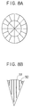
- a phased array type ultrasonic transducer formed by a plurality of transducer elements as shown in Fig, 8A may be used instead of the concave shaped single plate ultrasonic transducer 32.
- the slits 51 can be formed on each electrode 50 corresponding to each transducer element as shown in Fig. 8B for example.
- the focal point position can be changed electrically, but even in this case, the pointers 41 and 42 of this second embodiment can be utilized advantageously as an indication of a reference point for the focal point.
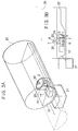
- This third embodiment concerns with the configuration of the ultrasonic wave applicator in a form of a body cavity probe that can be used in the ultrasonic wave medical treatment apparatus suitable for use in conjunction with the MRI. Consequently, the body cavity probe of this third embodiment described below can be used in the overall configuration similar to that of Fig. 1 instead of the ultrasonic wave applicator 1 of the first embodiment described above.
- a body cavity probe 90 is formed to have a configuration as shown in Fig. 9, which comprises a balloon 91 located at an end of a probe body 90A which is to be expanded by a water supplied from an external water circuit (not shown), a surface coil 92 attached on an upper surface of the balloon 91 which functions as a receiver coil for the MRI, and an ultrasonic transducer 93 located at the end of the probe body 90A below the balloon 91 which is formed by a number of piezoelectric elements to be phase controlled independently from each other.
- the ultrasonic transducer 93 of this third embodiment can shift the position of the focal point of the generated ultrasonic waves by appropriately controlling the phases of the piezoelectric elements just as in the phased array type ultrasonic transducer of the first embodiment described above.
- the position of the treatment target portion is determined first by obtaining the MR image by using a usual external receiver coil (not shown) rather than this body cavity probe 90. Then, this body cavity probe 90 is inserted into a body cavity of the patient to a position from which the treatment target portion can be treated effectively. After the body cavity probe 90 is positioned appropriately within the body cavity, the water is supplied into the balloon 91 to expand it such that the body cavity probe 90 can be fixed at that position as the expanded balloon 91 is pressed against the inner wall of the body cavity. Then, the MR signals generated in response to the application of the RF pulses are received by the surface coil 92, to obtain the MR image of the treatment target portion at a high S/N ratio.
- the ultrasonic waves focused onto the treatment target portion are irradiated from the ultrasonic transducer 93 to carry out the treatment.
- the MR image is obtained again in the similar manner in order to check the treatment effect.
- the initial determination of the treatment target portion may be achieved by monitoring a rough position of the body cavity probe 90 within the body cavity in real time by means of an ultrasound imaging device, or by monitoring the interior of the body cavity in real time by means of an optical fiber used endoscopically, instead of using the MRI as described above.
- the subsequent positioning of the body cavity probe 90 may also be achieved in these manners.
- the surface coil 91 as a transmitter coil for transmitting radio frequency pulses to the treatment target portion such that the thermal treatment can be applied to the treatment target portion by the heat induced by the radio frequency pulses.
- this configuration of Fig. 9 may be modified as shown in Fig. 10 in which the balloon 91 is replaced by double balloons 94 and 95, of which the outer balloon 94 is expanded similarly to the balloon 91, while the inner balloon 95 is formed such that the shaded region having the surface coil 92 and the ultrasonic transducer 93 provided thereon can be freely rotatable, so that the orientation of the surface coil 92 and the ultrasonic transducer 93 can be changed by rotating this rotatable portion of the inner balloon 95 even after the position of the body cavity probe as a whole is fixed by the expanded outer balloon 94.
- this outer balloon 94 it is also possible to make this outer balloon 94 to be substantially larger in the axial direction of the probe body 90A such that the inner balloon 95 can be moved in the axial direction as well. In this manner, the positioning with respect to the treatment target portion can be carried out after the body cavity probe 90 is inserted into the body cavity, without determining the treatment target portion in advance by using the MRI.
- the focal point position of the ultrasonic waves can be shifted three dimensionally by incorporating the rotational and translational movements of the ultrasonic transducer.
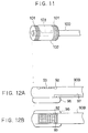
- Fig. 9 may be modified as shown in Fig. 11 in which coils 101 capable of generating a uniform magnetic field in the circumferential direction are provided around a cylindrical balloon 102, while an ultrasonic transducer 103 is provided on a probe body 100 which is both rotatable in the circumferential direction and movable in the axial direction and located within the balloon 102, such that the MR image can be obtained uniformly aoeong the circumferential direction, and the positioning of the body cavity probe can be achieved by fixing the balloon 102 while rotating and moving the probe body 100.
- the coils 101 are made to be solenoid coils wound in opposite directions which are attached at opposite ends of the balloon 102, such that the MR images at a high S/N ratio can be obtained at a region between these two coils 101.
- the water to be supplied into the balloon of the body cavity probe according to this third embodiment should preferably be the ion exchanged water or the pure water rather than the tap water.
- Fig. 9 it is also possible to modify the configuration of Fig. 9 as shown in Figs. 12A and 12B in which the surface coil 92 and the ultrasonic transducer 93 are provided on the upper side of the probe body 90B such that the surface coil 92 encloses the ultrasonic transducer 93, and a balloon 96 is provided on the lower side of the probe body 90B and filled with an externally supplied air through a pipe 97 formed within the probe body 90B, such that the surface coil 92 and the ultrasonic transducer 93 are pressed against the inner wall of the body cavity directly as the balloon 96 is expanded by the air at the opposite side.
- the material to be poured into the balloon 96 is not necessarily limited to the air, and can be anything that can expand the balloon 96.
- This catheter for thrombolysis is a device used for injecting the thrombolytic agent in a vicinity of the treatment target portion within the blood vessel and then irradiating the ultrasonic waves onto the treatment target portion so as to improve the treatment effect, although the injection of the thrombolytic agent is not absolutely necessary in every case.
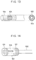
- the body cavity probe can be formed as shown in Fig. 13, which has coaxially arranged ultrasonic transducer 104 on an outer side and solenoid coil 105 on an inner side, where the ultrasonic transducer 104 is formed by a number of rectangular piezoelectric elements attached around an outer circumference of the body cavity probe to surround the solenoid coil 105.
- This body cavity probe of Fig. 13 has coaxially arranged ultrasonic transducer 104 on an outer side and solenoid coil 105 on an inner side, where the ultrasonic transducer 104 is formed by a number of rectangular piezoelectric elements attached around an outer circumference of the body cavity probe to surround the solenoid coil 105.
- the MRI images at a high S/N ratio can be obtained uniformly along the circumferential direction to monitor the interior of the blood vessel into which the catheter is inserted for the purpose of observing the treatment effect, while injecting the thrombolytic agent from the catheter and irradiating the ultrasonic waves from the ultrasonic transducer 104.
- the ultrasonic transducer in the body cavity probe of this third embodiment by the other treatment device such as a laser emitter.
- the configuration of Fig. 11 can be modified as shown in Fig. 14 in which the ultrasonic transducer 103 is replaced by a laser emitter 106, such that the laser beam can be irradiated onto the treatment target portion around the body cavity by rotating the probe body 100 so as to carry out the thermal or opto-chemical treatment.
- this configuration of Fig. 14 in a case of carrying out the thermal treatment, there is a danger for damaging the normal tissues in a vicinity of the body cavity as well, so that water filling inside the balloon 102 should be circulated by an external water circuit for the purpose of cooling.
- the opto-chemical treatment is that in which the agent having a tumor selectivity which can reveal the anti-tumor effect upon the irradiation by the laser beam is injected, and then the laser beam is irradiated thereon.
- the injection of the tumor selectivity of the injected agent can be improved by carrying out the injection while monitoring the MR images obtained by this body cavity probe.
- the imaging parameters of the MRI can be affected by the factors such as the temperature that can be changed by the treatment. Consequently, the timing for the MR image taking by this body cavity probe should be sufficiently separated from the timing for the treatment by this body cavity probe in order to remove the possible influence of the treatment from the obtained MR image, so that the accurate determination of treatment position or accurate judgement of treatment effect can be made on a basis of the MR image.
- the real time property is a crucial requirement, so that the high speed or ultra high speed imaging pulse sequence should be employed for this purpose, even though the S/N ratio must be sacrificed to some extent in such an imaging pulse sequence.
- the treatment and the imaging can be carried out simultaneously in parallel, at sufficiently separated treatment region and imaging region sequentially, so as to improve the efficiency of the overall operation and realizing the satisfactory real time property without sacrificing the S/N ratio.
- the imaging time can be shortened by limiting the imaging regions to be sufficiently small, so that the high precision imaging can be achieved by the normal speed imaging pulse sequence such as that for the usual spin echo imaging.
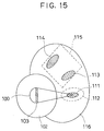
- the ultrasonic waves can be irradiated onto one treatment target portion 111 within an area 112, while at the same time the MR image can be taken from an area 115 sufficiently separated from the area 102 to be free of the influence of the ultrasonic wave irradiation, for the purpose of judging the treatment effect on a previously treated treatment target portion 113 or determining the treatment position for a next treatment target portion 114 within this area 115, for example.
- the body cavity probe of Fig. 11 is used as the MR image can be taken uniformly in the circumferential direction in this body cavity probe.
- the body cavity probe equipped with a surface coil such as that shown in Fig. 9 which has the sensitivity only in one direction may also be adapted to the above procedure by enlarging the imaging region to be sufficiently larger than the region influenced by the treatment.
- the selective excitation method can be employed in the MRI to realize the high resolution in a limited imaging region.
- this third embodiment it becomes possible to obtain the MR images of the treatment target portion at a high resolution all the times, so that the initial positioning, the treatment effect confirmation, and the treatment monitoring can be realized in real time by using these MR images.
- This fourth embodiment concerns with the modified configuration of the ultrasonic wave applicator in the ultrasonic wave medical treatment apparatus.
- the ultrasonic wave applicator 120 comprises an ultrasonic transducer 125 formed by at least one piezoelectric elements for generating the ultrasonic waves, which is coupled with a patient 121 through a water bag 124 containing the coupling fluid.
- the ultrasonic transducer 125 is driven by a driving circuit 127 to generate the ultrasonic waves focused on a focal point 123 located within a treatment target portion 122 of the patient 121.
- the treatment is monitored by an ultrasound imaging device 128 which obtains a tomographic image on a plane containing the focal point 123 of the ultrasonic transducer 125 from the reflected ultrasound signals detected by an ultrasonic probe 126 mounted at a center of the ultrasonic transducer 125 and displays the obtained ultrasound tomographic image on a CRT 129.
- the coupling fluid contained in the water bag 124 is cooled by being circulated by the a cooling device 131 according to the temperature of the coupling fluid within the water bag 124 measured by a temperature sensor 130, in order to prevent the potentially dangerous heat generation due to the ultrasonic wave irradiation at the ultrasonic transducer 125 and the body surface that can cause the burning of the body surface.
- a control circuit 132 controls the driving circuit 127 and the cooling device 131 to control the irradiation of the ultrasonic waves, the change of the ultrasonic wave intensity, the setting of the cooling temperature, etc.
- the ultrasonic wave applicator 120 is fixedly supported with respect to the patient's body by means of an applicator fixing belts 133 for binding the ultrasonic wave applicator 120 and the patient 121 together, so as to prevent the displacement of the focal point 123 of the ultrasonic transducer 125 in the ultrasonic wave applicator 120 which has been positioned with respect to the treatment target portion 122 within the patient's body due to the body movement or the respiration by the patient 121.
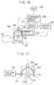
- the ultrasonic wave applicator 120' may be formed as shown in Fig. 17 which is equipped with a rubber ring 144 at the edge of the ultrasonic wave applicator 120' for sucking onto the body surface, and a suction pump 135 for vacuuming the air from a space between the ultrasonic wave applicator 120' and the body surface enclosed by the rubber ring 144 after the rubber ring 144 is attached onto the body surface such that the ultrasonic wave applicator 120' can be fixedly supported with respect to the patient 121.
- the ultrasonic wave applicator 120 may be supported by a support arm 136 controlled by an arm control mechanism 137 as shown in Fig. 18.
- the arm control mechanism 137 can be controlled by the controller 132 such that the supporting arm 136 can set the ultrasonic wave applicator 120 in a motion which closely follows the patient's body movement due to the respiration, so as to prevent the displacement of the focal point 123 from the treatment target portion 122 as much as possible.
- a coupling adjustment agent mixing device 139 is provided in conjunction with the cooling device 131 so as to change the mixing rate of the water and the coupling adjustment agent in the coupling fluid.
- the coupling adjustment agent mixing device 139 changes the mixing rate of the water and the coupling adjustment agent in a form of a sonic speed adjustment agent such as the propanol according to the temperature of the coupling fluid within the water bag 124 so as to compensate the sonic speed difference between the coupling fluid and the living tissues and suppress the deflection of the ultrasonic waves.
- a sonic speed adjustment agent such as the propanol
- the control circuit 132 has a table of data for the sonic speeds corresponding to various mixing rates of the sonic speed adjustment agent and the water at various temperatures, so that the control circuit 132 can determine the appropriate mixing rate according to this table of data, the temperature of the coupling fluid within the water bag 124, and the sonic speed in the living tissues, and controls the coupling adjustment agent mixing device 139 to realize the determined mixing rate such that the sonic speed in the coupling fluid becomes equal to that in the living tissues.
- the sonic speed in the living tissues may be fixed to an approximate value of 1570 m/s for simplicity.
- Fig. 19 can be modified as shown in Fig. 20A to incorporate a transmitting transducer 141 and a receiving transducer 143 on opposite sides at the edge of the ultrasonic transducer 125, which are connected with a transmitter circuit 142 and a receiver circuit 144, respectively, controlled by the control circuit 132.
- the sonic speed in the coupling fluid is measured in a state in which the ultrasonic wave applicator 120 is not in contact with the body surface as follows.
- the control circuit 132 controls the transmitter circuit 142 to drive the transmitting transducer 141 to emit the ultrasonic wave which is subsequently propagated through the coupling fluid.
- the receiver circuit 144 notifies this to the control circuit 132, such that the control circuit 132 calculates the propagation time T1 between the emission of the ultrasonic wave at the transmitting transducer 141 and the reception of the ultrasonic wave at the receiving transducer 143.
- the ultrasonic probe 126 which is made to be movably fixed by means of a pulse motor (not shown) is held to be vertical with respect to the body surface, and using an object within the patient's body such as a rib which has a large reflection echo as an ultrasonic marker 145, the ultrasonic wave applicator 120 or the ultrasonic probe 126 is moved such that the ultrasonic marker 145 is located on a central axis in the ultrasound image as shown in Fig. 21A, at which the ultrasonic image appears as shown in Fig. 21C.
- the propagation time t1 for the ultrasonic wave between the ultrasonic probe 126 and the body surface the propagation time t2 for the ultrasonic wave between the ultrasonic probe 126 and the ultrasonic marker 145, and the height h between the ultrasonic probe 126 and the body surface are measured.
- the ultrasonic wave applicator 120 or the ultrasonic probe 126 is inclined for an angle ⁇ with respect to the body surface as in a state (2) shown in Fig. 21B, at which the ultrasound image appears as shown in Fig. 21D, and then moved in parallel to the body surface until the ultrasonic marker 145 comes on the central axis in the ultrasonic image as in a state (3) shown in Fig.
- the coupling adjustment agent other than the sonic speed adjustment agent such as a glycerol which functions as an acoustic impedance adjustment agent for adjusting the acoustic impedance of the coupling fluid to suppress the reflection of the ultrasonic waves at the body surface, rather than adjusting the sonic speed in the coupling fluid.
- the deflection of the ultrasonic waves at the body surface due to the sonic speed difference can be compensated by using the ultrasonic transducer 125 of a phased array type and changing the driving phases of the driving circuit 127 for the piezoelectric elements of the ultrasonic transducer 125 by a delay circuit 140 shown in Fig. 19 to adjust the position of the focal point 123 such that the de-focusing due to the deflection can be compensated.
- propanol and the glycerol mentioned above may be replaced by any other known fluid materials having the similar functions as these such as other alcoholic acids in this fourth embodiment.
- This fourth embodiment concerns with the modified configuration of the ultrasonic wave applicator in the ultrasonic wave medical treatment apparatus.
- the ultrasonic wave applicator 150 comprises an ultrasonic transducer 155 formed by at least one piezoelectric elements for generating the ultrasonic waves, which is coupled with a patient 151 through a water bag 154 containing the coupling fluid, and supported by an arm control mechanism 166.
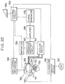
- the ultrasonic transducer 155 is driven by a driving signal generated by a signal generator 159 and transmitted via an amplifier 158, an impedance matching circuit 157, and a wattmeter 156, to generate the ultrasonic waves focused on a focal point 153 located within a treatment target portion 152 of the patient 151.
- the treatment is monitored by an ultrasound imaging device 161 which obtains a tomographic image on a plane containing the focal point 153 of the ultrasonic transducer 155 from the reflected ultrasound signals detected by an ultrasonic probe 160 mounted on the ultrasonic wave applicator 150 and displays the obtained ultrasound tomographic image on a CRT 162.
- the coupling fluid contained in the water bag 154 is cooled by being circulated by the a cooling device 164 in order to prevent the potentially dangerous heat generation due to the ultrasonic wave irradiation at the ultrasonic transducer 155 and the body surface that can cause the burning of the body surface.
- a control circuit 163 is equipped with a console 165 and controls the ultrasonic imaging device 161 and the arm control mechanism 166, as well as the signal generator 159, and the cooling device 164 to control the irradiation of the ultrasonic waves, the change of the ultrasonic wave intensity, the driving frequency of the ultrasonic transducer 155, the setting of the cooling temperature, etc.
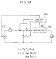
- the piezoelectric elements of the ultrasonic transducer 155 has a fixed mechanical resonance frequency determined by their thickness, and this mechanical resonance frequency coincides with an anti-resonance frequency in the electric impedance characteristic of these piezoelectric elements, as indicated in Figs. 23A and 23B.
- the electrically most efficient manner of using these piezoelectric elements will be to carry out a tuning at this frequency to make the impedance matching with the output impedance of the amplifier 158 at the impedance matching circuit 157.
- the control circuit 163 controls the driving frequency of the signal generator 159 by monitoring the passing electric powers in the normal and reverse directions at the wattmeter 156 such that the reflected electric power from the piezoelectric elements becomes minimum.
- the acoustic output cannot be obtained when the driving frequency of the piezoelectric elements largely deviates from the mechanical resonance frequency of the piezoelectric elements, so that the driving frequency is made to be variable within a range of ⁇ 15 % of the mechanical resonance frequency.
- the driving frequency can be determined by obtaining the change ⁇ W of the reflected electric power in response to the change of the driving frequency from the current driving frequency by ⁇ f, and controlling the driving frequency in a direction to make ⁇ W/ ⁇ f minimum as indicated in Fig. 23B.
- the impedance for the output terminal of the amplifier 158 changes as the driving frequency changes, so that the electric power inputted into the piezoelectric elements also changes, and therefore the control circuit 163 also controls the driving voltage of the signal generator 159 such that the input energy at the focal point 153 of the ultrasonic waves per unit time becomes constant.
- the heat generation at the focal point 153 is proportional to the cube of the frequency because of the frequency dependence of the focusing effect and the attenuation rate of the ultrasonic waves, so that in view of this fact, the theoretical value for the heat generation at the focal point 153 can be calculated from the frequency, the input power, and the electro-mechanical conversion efficiency, and the driving voltage of the signal generator 159 can be controlled to make this calculated heat generation at the focal point 153 to be constant instead.
- control circuit 163 can also control the driving frequency of the signal generator 159, either step-wise or continuously, while the ultrasonic waves are irradiated from the ultrasoic wave applicator 150 onto the treatment target portion 153, in order to suppress the cavitations generated at a time of a high power input.
- this fifth embodiment it becomes possible to realize the impedance matching by simply adjusting the driving frequency for the ultrasonic transducer, and to suppress the generation of the cavitations by actively changing the driving frequency constantly, such that the effective, efficient, and safe treatment of the patient can be realized.
Landscapes
- Health & Medical Sciences (AREA)
- Engineering & Computer Science (AREA)
- Biomedical Technology (AREA)
- Nuclear Medicine, Radiotherapy & Molecular Imaging (AREA)
- Radiology & Medical Imaging (AREA)
- Life Sciences & Earth Sciences (AREA)
- Animal Behavior & Ethology (AREA)
- General Health & Medical Sciences (AREA)
- Public Health (AREA)
- Veterinary Medicine (AREA)
- Physics & Mathematics (AREA)
- Condensed Matter Physics & Semiconductors (AREA)
- General Physics & Mathematics (AREA)
- Surgical Instruments (AREA)
- Magnetic Resonance Imaging Apparatus (AREA)
- Thermotherapy And Cooling Therapy Devices (AREA)
Applications Claiming Priority (3)
| Application Number | Priority Date | Filing Date | Title |
|---|---|---|---|
| JP04955193A JP3860227B2 (ja) | 1993-03-10 | 1993-03-10 | Mriガイド下で用いる超音波治療装置 |
| JP4955193 | 1993-03-10 | ||
| EP94103587A EP0614651B1 (de) | 1993-03-10 | 1994-03-09 | Ultraschallwellen medizinisches Behandlungsgerät, verwendbar im Gebrauch bei der Führung durch Magnet-Resonanz-Bilddarstellung |
Related Parent Applications (1)
| Application Number | Title | Priority Date | Filing Date |
|---|---|---|---|
| EP94103587A Division EP0614651B1 (de) | 1993-03-10 | 1994-03-09 | Ultraschallwellen medizinisches Behandlungsgerät, verwendbar im Gebrauch bei der Führung durch Magnet-Resonanz-Bilddarstellung |
Publications (3)
| Publication Number | Publication Date |
|---|---|
| EP0938914A2 true EP0938914A2 (de) | 1999-09-01 |
| EP0938914A3 EP0938914A3 (de) | 1999-11-10 |
| EP0938914B1 EP0938914B1 (de) | 2003-02-19 |
Family
ID=12834334
Family Applications (3)
| Application Number | Title | Priority Date | Filing Date |
|---|---|---|---|
| EP94103587A Expired - Lifetime EP0614651B1 (de) | 1993-03-10 | 1994-03-09 | Ultraschallwellen medizinisches Behandlungsgerät, verwendbar im Gebrauch bei der Führung durch Magnet-Resonanz-Bilddarstellung |
| EP99111088A Expired - Lifetime EP0938914B1 (de) | 1993-03-10 | 1994-03-09 | Medizinisches Ultraschall-Behandlungsgerät mit Magnet-Resonanz-Bilddarstellung |
| EP99111087A Withdrawn EP0938913A3 (de) | 1993-03-10 | 1994-03-09 | Ultraschallwellen medizinisches Behandlungsgerät, verwendbar im Gebrauch bei der Führung durch Magnet-Resonanz- Bilddarstellung |
Family Applications Before (1)
| Application Number | Title | Priority Date | Filing Date |
|---|---|---|---|
| EP94103587A Expired - Lifetime EP0614651B1 (de) | 1993-03-10 | 1994-03-09 | Ultraschallwellen medizinisches Behandlungsgerät, verwendbar im Gebrauch bei der Führung durch Magnet-Resonanz-Bilddarstellung |
Family Applications After (1)
| Application Number | Title | Priority Date | Filing Date |
|---|---|---|---|
| EP99111087A Withdrawn EP0938913A3 (de) | 1993-03-10 | 1994-03-09 | Ultraschallwellen medizinisches Behandlungsgerät, verwendbar im Gebrauch bei der Führung durch Magnet-Resonanz- Bilddarstellung |
Country Status (4)
| Country | Link |
|---|---|
| US (2) | US5590653A (de) |
| EP (3) | EP0614651B1 (de) |
| JP (1) | JP3860227B2 (de) |
| DE (2) | DE69428146T2 (de) |
Families Citing this family (288)
| Publication number | Priority date | Publication date | Assignee | Title |
|---|---|---|---|---|
| DE19515748A1 (de) * | 1995-04-28 | 1996-10-31 | Siemens Ag | Gerät zur Behandlung mit akustischen Wellen |
| US5590657A (en) * | 1995-11-06 | 1997-01-07 | The Regents Of The University Of Michigan | Phased array ultrasound system and method for cardiac ablation |
| DE69634976T2 (de) * | 1995-12-14 | 2006-04-20 | Koninklijke Philips Electronics N.V. | Verfahren und gerät zum erhitzen mit ultraschall, gesteuert durch bilderzeugung mit magnetischer resonanz |
| US6229762B1 (en) * | 1996-08-26 | 2001-05-08 | The United States Of America As Represented By The Secretary Of The Navy | Acoustic sensor for a point in space |
| DE69728490T2 (de) * | 1996-11-12 | 2005-03-24 | Philips Medical Systems (Cleveland), Inc., Cleveland | Gerät für die magnetische Kernresonanz |
| DE19718511C5 (de) * | 1997-05-02 | 2010-10-21 | Sanuwave, Inc., | Gerät zur Applikation von akustischen Stoßwellen |
| ATE419789T1 (de) | 1997-05-23 | 2009-01-15 | Prorhythm Inc | Wegwerfbarer fokussierender ultraschallapplikator hoher intensität |
| DE19742379C1 (de) * | 1997-09-25 | 1999-02-11 | Siemens Ag | Verfahren zum Betrieb eines Ultraschall-Therapiegeräts sowie entsprechendes Gerät |
| DE19745400C1 (de) | 1997-10-14 | 1999-04-15 | Siemens Ag | Vorrichtung zur Ultraschalltherapie einer weiblichen Brust |
| DE19800416C2 (de) * | 1998-01-08 | 2002-09-19 | Storz Karl Gmbh & Co Kg | Vorrichtung zur Behandlung von Körpergewebe, insbesondere von oberflächennahem Weichgewebe, mittels Ultraschall |
| CN1058905C (zh) * | 1998-01-25 | 2000-11-29 | 重庆海扶(Hifu)技术有限公司 | 高强度聚焦超声肿瘤扫描治疗系统 |
| AU2003200533B2 (en) * | 1998-01-25 | 2005-04-07 | Chongqing Haifu Medical Technology Co., Ltd. | A High Intensity Focused Ultrasound System for Scanning and Curing Tumors |
| US6344037B1 (en) | 1998-02-03 | 2002-02-05 | Scimed Life Systems, Inc. | Integrated coaxial transmission line and flexible drive cable |
| US6017312A (en) * | 1998-02-03 | 2000-01-25 | Boston Scientific Corporation | Multi-channel rotary transformer |
| US6120454A (en) * | 1998-02-03 | 2000-09-19 | Boston Scientific Corporation | Annular array ultrasound catheter |
| US6360116B1 (en) | 1998-02-27 | 2002-03-19 | Varian Medical Systems, Inc. | Brachytherapy system for prostate cancer treatment with computer implemented systems and processes to facilitate pre-operative planning and post-operative evaluations |
| US6327490B1 (en) | 1998-02-27 | 2001-12-04 | Varian Medical Systems, Inc. | Brachytherapy system for prostate cancer treatment with computer implemented systems and processes to facilitate pre-implantation planning and post-implantation evaluations with storage of multiple plan variations for a single patient |
| US6385474B1 (en) | 1999-03-19 | 2002-05-07 | Barbara Ann Karmanos Cancer Institute | Method and apparatus for high-resolution detection and characterization of medical pathologies |
| JPH11267133A (ja) | 1998-03-25 | 1999-10-05 | Olympus Optical Co Ltd | 治療装置 |
| US6298259B1 (en) | 1998-10-16 | 2001-10-02 | Univ Minnesota | Combined magnetic resonance imaging and magnetic stereotaxis surgical apparatus and processes |
| DE19905239B4 (de) * | 1999-02-02 | 2006-08-24 | Wendt, Oliver, Dipl.-Ing. | Positioniereinrichtung zur Positionierung von medizinischen Werkzeugen zur MR-gestützten Untersuchung und Behandlung von Körperteilen |
| US6591127B1 (en) * | 1999-03-15 | 2003-07-08 | General Electric Company | Integrated multi-modality imaging system and method |
| US6643535B2 (en) * | 1999-05-26 | 2003-11-04 | Endocare, Inc. | System for providing computer guided ablation of tissue |
| US7363071B2 (en) | 1999-05-26 | 2008-04-22 | Endocare, Inc. | Computer guided ablation of tissue using integrated ablative/temperature sensing devices |
| US7520856B2 (en) * | 1999-09-17 | 2009-04-21 | University Of Washington | Image guided high intensity focused ultrasound device for therapy in obstetrics and gynecology |
| US7510536B2 (en) * | 1999-09-17 | 2009-03-31 | University Of Washington | Ultrasound guided high intensity focused ultrasound treatment of nerves |
| US20040097996A1 (en) | 1999-10-05 | 2004-05-20 | Omnisonics Medical Technologies, Inc. | Apparatus and method of removing occlusions using an ultrasonic medical device operating in a transverse mode |
| US6551337B1 (en) | 1999-10-05 | 2003-04-22 | Omnisonics Medical Technologies, Inc. | Ultrasonic medical device operating in a transverse mode |
| US6660013B2 (en) * | 1999-10-05 | 2003-12-09 | Omnisonics Medical Technologies, Inc. | Apparatus for removing plaque from blood vessels using ultrasonic energy |
| US6524251B2 (en) | 1999-10-05 | 2003-02-25 | Omnisonics Medical Technologies, Inc. | Ultrasonic device for tissue ablation and sheath for use therewith |
| US6371915B1 (en) | 1999-11-02 | 2002-04-16 | Scimed Life Systems, Inc. | One-twelfth wavelength impedence matching transformer |
| US6603991B1 (en) * | 1999-11-24 | 2003-08-05 | Koninklijke Philips Electronics N.V. | Method and apparatus for dual mode medical imaging system |
| WO2001050156A1 (en) * | 1999-12-30 | 2001-07-12 | Transurgical, Inc. | Interleaved operation of mri and electronic equipment |
| US7399284B2 (en) * | 2000-05-22 | 2008-07-15 | Miwa Science Laboratory Inc. | Ultrasonic irradiation apparatus |
| US6418337B1 (en) * | 2000-06-15 | 2002-07-09 | Autolitt Inc. | MRI guided hyperthermia surgery |
| US8256430B2 (en) | 2001-06-15 | 2012-09-04 | Monteris Medical, Inc. | Hyperthermia treatment and probe therefor |
| RU2176535C1 (ru) * | 2000-06-16 | 2001-12-10 | Завод "Двигатель" | Аппарат для ультразвуковой терапии |
| DE10033063A1 (de) * | 2000-07-07 | 2002-01-24 | Brainlab Ag | Verfahren zur atmungskompensierten Strahlenbehandlung |
| US6733450B1 (en) * | 2000-07-27 | 2004-05-11 | Texas Systems, Board Of Regents | Therapeutic methods and apparatus for use of sonication to enhance perfusion of tissue |
| US6582381B1 (en) * | 2000-07-31 | 2003-06-24 | Txsonics Ltd. | Mechanical positioner for MRI guided ultrasound therapy system |
| US6459923B1 (en) * | 2000-11-22 | 2002-10-01 | General Electric Company | Intervention bed for a medical imaging device |
| US6618620B1 (en) | 2000-11-28 | 2003-09-09 | Txsonics Ltd. | Apparatus for controlling thermal dosing in an thermal treatment system |
| SE0100160D0 (sv) * | 2001-01-22 | 2001-01-22 | Atos Medical Ab | Method and apparatus for high energetic ultrasonic tissue treatment |
| US20050080468A1 (en) * | 2001-03-26 | 2005-04-14 | Lawrence C. Christman | Methods and apparatus for treating diseased tissue |
| US7211044B2 (en) * | 2001-05-29 | 2007-05-01 | Ethicon Endo-Surgery, Inc. | Method for mapping temperature rise using pulse-echo ultrasound |
| US7473224B2 (en) * | 2001-05-29 | 2009-01-06 | Ethicon Endo-Surgery, Inc. | Deployable ultrasound medical transducers |
| US7846096B2 (en) | 2001-05-29 | 2010-12-07 | Ethicon Endo-Surgery, Inc. | Method for monitoring of medical treatment using pulse-echo ultrasound |
| US6702751B2 (en) * | 2001-06-27 | 2004-03-09 | Dicomit Dicom Information Technologies, Corp. | Method and system for optimally timing scans of a selected part of a patient |
| US6862468B2 (en) * | 2001-09-28 | 2005-03-01 | Scimed Life Systems, Inc. | Systems and methods for magnetic resonance imaging elastography |
| JP2003135458A (ja) * | 2001-10-30 | 2003-05-13 | Hitachi Ltd | 超音波探触子、超音波撮像装置及び撮像方法 |
| WO2003051217A2 (en) | 2001-12-14 | 2003-06-26 | Monteris Medical Inc. | Hyperthermia treatment and probe therefor |
| SE520857C2 (sv) * | 2002-01-15 | 2003-09-02 | Ultrazonix Dnt Ab | Anordning med såväl terapeutiska som diagnostiska givare för mini-invasiv ultraljudsbehandling av ett objekt, där den terapeuti ska givaren är termiskt isolerad |
| US20030181890A1 (en) * | 2002-03-22 | 2003-09-25 | Schulze Dale R. | Medical device that removably attaches to a bodily organ |
| US7128711B2 (en) * | 2002-03-25 | 2006-10-31 | Insightec, Ltd. | Positioning systems and methods for guided ultrasound therapy systems |
| US7285092B2 (en) | 2002-12-18 | 2007-10-23 | Barbara Ann Karmanos Cancer Institute | Computerized ultrasound risk evaluation system |
| WO2003096883A2 (en) | 2002-05-16 | 2003-11-27 | Barbara Ann Karmanos Cancer Institute | Combined diagnostic and therapeutic ultrasound system |
| US7967839B2 (en) * | 2002-05-20 | 2011-06-28 | Rocky Mountain Biosystems, Inc. | Electromagnetic treatment of tissues and cells |
| US6926672B2 (en) * | 2002-12-18 | 2005-08-09 | Barbara Ann Karmanos Cancer Institute | Electret acoustic transducer array for computerized ultrasound risk evaluation system |
| US6837854B2 (en) * | 2002-12-18 | 2005-01-04 | Barbara Ann Karmanos Cancer Institute | Methods and systems for using reference images in acoustic image processing |
| US8088067B2 (en) * | 2002-12-23 | 2012-01-03 | Insightec Ltd. | Tissue aberration corrections in ultrasound therapy |
| US20040162507A1 (en) * | 2003-02-19 | 2004-08-19 | Assaf Govari | Externally-applied high intensity focused ultrasound (HIFU) for therapeutic treatment |
| US7611462B2 (en) * | 2003-05-22 | 2009-11-03 | Insightec-Image Guided Treatment Ltd. | Acoustic beam forming in phased arrays including large numbers of transducer elements |
| US7377900B2 (en) * | 2003-06-02 | 2008-05-27 | Insightec - Image Guided Treatment Ltd. | Endo-cavity focused ultrasound transducer |
| EP1493389A1 (de) * | 2003-07-01 | 2005-01-05 | Siemens Aktiengesellschaft | Verfahren und Einrichtung zum Erzeugen eines Röntgenbildes aus der Fokusregion eines Lithotripters |
| US7438714B2 (en) * | 2003-09-12 | 2008-10-21 | Boston Scientific Scimed, Inc. | Vacuum-based catheter stabilizer |
| US7970452B2 (en) * | 2003-09-30 | 2011-06-28 | Hologic, Inc. | Open architecture imaging apparatus and coil system for magnetic resonance imaging |
| US20080077005A1 (en) * | 2004-08-12 | 2008-03-27 | Piron Cameron A | System and Method for Multimodality Breast Imaging |
| US7908690B2 (en) * | 2003-09-30 | 2011-03-22 | Sentinelle Medical, Inc. | Supine patient support for medical imaging |
| US7379769B2 (en) | 2003-09-30 | 2008-05-27 | Sunnybrook Health Sciences Center | Hybrid imaging method to monitor medical device delivery and patient support for use in the method |
| JPWO2005039416A1 (ja) * | 2003-10-23 | 2007-11-22 | 株式会社日立メディコ | 治療支援用画像処理装置 |
| US8206299B2 (en) * | 2003-12-16 | 2012-06-26 | University Of Washington | Image guided high intensity focused ultrasound treatment of nerves |
| US7794414B2 (en) * | 2004-02-09 | 2010-09-14 | Emigrant Bank, N.A. | Apparatus and method for an ultrasonic medical device operating in torsional and transverse modes |
| US20050187514A1 (en) * | 2004-02-09 | 2005-08-25 | Omnisonics Medical Technologies, Inc. | Apparatus and method for an ultrasonic medical device operating in a torsional mode |
| US20050228286A1 (en) * | 2004-04-07 | 2005-10-13 | Messerly Jeffrey D | Medical system having a rotatable ultrasound source and a piercing tip |
| US20050240105A1 (en) * | 2004-04-14 | 2005-10-27 | Mast T D | Method for reducing electronic artifacts in ultrasound imaging |
| US20050240124A1 (en) * | 2004-04-15 | 2005-10-27 | Mast T D | Ultrasound medical treatment system and method |
| US20050234438A1 (en) * | 2004-04-15 | 2005-10-20 | Mast T D | Ultrasound medical treatment system and method |
| US7494467B2 (en) * | 2004-04-16 | 2009-02-24 | Ethicon Endo-Surgery, Inc. | Medical system having multiple ultrasound transducers or an ultrasound transducer and an RF electrode |
| US20050267488A1 (en) * | 2004-05-13 | 2005-12-01 | Omnisonics Medical Technologies, Inc. | Apparatus and method for using an ultrasonic medical device to treat urolithiasis |
| US20050256410A1 (en) * | 2004-05-14 | 2005-11-17 | Omnisonics Medical Technologies, Inc. | Apparatus and method for an ultrasonic probe capable of bending with aid of a balloon |
| US20050256405A1 (en) * | 2004-05-17 | 2005-11-17 | Makin Inder Raj S | Ultrasound-based procedure for uterine medical treatment |
| US7883468B2 (en) * | 2004-05-18 | 2011-02-08 | Ethicon Endo-Surgery, Inc. | Medical system having an ultrasound source and an acoustic coupling medium |
| US20050261587A1 (en) * | 2004-05-20 | 2005-11-24 | Makin Inder R S | Ultrasound medical system and method |
| US7951095B2 (en) * | 2004-05-20 | 2011-05-31 | Ethicon Endo-Surgery, Inc. | Ultrasound medical system |
| US7473250B2 (en) * | 2004-05-21 | 2009-01-06 | Ethicon Endo-Surgery, Inc. | Ultrasound medical system and method |
| US20050261588A1 (en) * | 2004-05-21 | 2005-11-24 | Makin Inder Raj S | Ultrasound medical system |
| US7806839B2 (en) | 2004-06-14 | 2010-10-05 | Ethicon Endo-Surgery, Inc. | System and method for ultrasound therapy using grating lobes |
| NL1026492C2 (nl) * | 2004-06-24 | 2005-12-28 | Pan Consult B V | Inrichting voor het met behulp van ultrageluid bestralen van een doelgebied in een menselijk of dierlijk lichaam. |
| GB2416458B (en) * | 2004-07-20 | 2008-11-26 | Sra Dev Ltd | Ultrasonic generator system |
| US7699780B2 (en) * | 2004-08-11 | 2010-04-20 | Insightec—Image-Guided Treatment Ltd. | Focused ultrasound system with adaptive anatomical aperture shaping |
| US8409099B2 (en) | 2004-08-26 | 2013-04-02 | Insightec Ltd. | Focused ultrasound system for surrounding a body tissue mass and treatment method |
| US9066679B2 (en) * | 2004-08-31 | 2015-06-30 | University Of Washington | Ultrasonic technique for assessing wall vibrations in stenosed blood vessels |
| GB0419954D0 (en) * | 2004-09-08 | 2004-10-13 | Advotek Medical Devices Ltd | System for directing therapy |
| AU2005284695A1 (en) * | 2004-09-16 | 2006-03-23 | University Of Washington | Acoustic coupler using an independent water pillow with circulation for cooling a transducer |
| US7833221B2 (en) * | 2004-10-22 | 2010-11-16 | Ethicon Endo-Surgery, Inc. | System and method for treatment of tissue using the tissue as a fiducial |
| US7452357B2 (en) * | 2004-10-22 | 2008-11-18 | Ethicon Endo-Surgery, Inc. | System and method for planning treatment of tissue |
| US20060089626A1 (en) * | 2004-10-22 | 2006-04-27 | Vlegele James W | Surgical device guide for use with an imaging system |
| WO2006057911A2 (en) * | 2004-11-22 | 2006-06-01 | Civco Medical Instruments Co., Inc. | Real time ultrasound monitoring of the motion of internal structures during respiration for control of therapy delivery |
| US20060116610A1 (en) * | 2004-11-30 | 2006-06-01 | Omnisonics Medical Technologies, Inc. | Apparatus and method for an ultrasonic medical device with variable frequency drive |
| WO2006059966A1 (en) * | 2004-11-30 | 2006-06-08 | Omnisonics Medical Technologies, Inc. | Ultrasonic medical device with variable frequency drive |
| CN100506323C (zh) | 2005-01-10 | 2009-07-01 | 重庆海扶(Hifu)技术有限公司 | 一体化超声治疗换能器装置 |
| NL1028029C2 (nl) * | 2005-01-14 | 2006-07-19 | Enraf Nonius B V | Inrichting voor het behandelen van een patient met ultrageluid, alsmede ultrageluidbehandelkop voor deze inrichting. |
| US7857775B2 (en) * | 2005-03-15 | 2010-12-28 | Syneron Medical Ltd. | Method for soft tissue treatment |
| US20060229597A1 (en) * | 2005-04-07 | 2006-10-12 | Mcintyre Jon T | Ultrasound medical device and related methods of use |
| US20070016039A1 (en) * | 2005-06-21 | 2007-01-18 | Insightec-Image Guided Treatment Ltd. | Controlled, non-linear focused ultrasound treatment |
| US20070016184A1 (en) * | 2005-07-14 | 2007-01-18 | Ethicon Endo-Surgery, Inc. | Medical-treatment electrode assembly and method for medical treatment |
| CN1903390B (zh) * | 2005-07-29 | 2010-10-06 | 重庆融海超声医学工程研究中心有限公司 | Mri引导的高强度聚焦超声治疗系统 |
| WO2007021958A2 (en) * | 2005-08-12 | 2007-02-22 | University Of Washington | Method and apparatus for preparing organs and tissues for laparoscopic surgery |
| US8784336B2 (en) | 2005-08-24 | 2014-07-22 | C. R. Bard, Inc. | Stylet apparatuses and methods of manufacture |
| WO2007035529A2 (en) * | 2005-09-16 | 2007-03-29 | University Of Washington | Thin-profile therapeutic ultrasound applicators |
| US8016757B2 (en) * | 2005-09-30 | 2011-09-13 | University Of Washington | Non-invasive temperature estimation technique for HIFU therapy monitoring using backscattered ultrasound |
| CN1966108A (zh) * | 2005-11-16 | 2007-05-23 | 上海爱申科技发展股份有限公司 | Hifu肿瘤消融系统 |
| CN101313354B (zh) * | 2005-11-23 | 2012-02-15 | 因赛泰克有限公司 | 超高密度超声阵列中的分级切换 |
| CN1990062B (zh) * | 2005-12-30 | 2012-03-21 | 重庆融海超声医学工程研究中心有限公司 | Mri/ct装置引导的高强度超声治疗系统 |
| US20070239011A1 (en) | 2006-01-13 | 2007-10-11 | Mirabilis Medica, Inc. | Apparatus for delivering high intensity focused ultrasound energy to a treatment site internal to a patient's body |
| US9207299B2 (en) * | 2006-02-28 | 2015-12-08 | Kabushiki Kaisha Toshiba | Magnetic resonance imaging system and magnetic resonance imaging apparatus |
| CA2649119A1 (en) | 2006-04-13 | 2007-12-13 | Mirabilis Medica, Inc. | Methods and apparatus for the treatment of menometrorrhagia, endometrial pathology, and cervical neoplasia using high intensity focused ultrasound energy |
| US20130190676A1 (en) | 2006-04-20 | 2013-07-25 | Limflow Gmbh | Devices and methods for fluid flow through body passages |
| CN101438182B (zh) * | 2006-04-24 | 2013-06-12 | 皇家飞利浦电子股份有限公司 | 用于电特性断层摄影的电场匀场 |
| US8235901B2 (en) * | 2006-04-26 | 2012-08-07 | Insightec, Ltd. | Focused ultrasound system with far field tail suppression |
| CN100486521C (zh) * | 2006-07-19 | 2009-05-13 | 西门子(中国)有限公司 | 一种在mri引导的医疗设备中传送磁共振信号的装置 |
| US20100030076A1 (en) * | 2006-08-01 | 2010-02-04 | Kobi Vortman | Systems and Methods for Simultaneously Treating Multiple Target Sites |
| CN100574829C (zh) * | 2006-08-24 | 2009-12-30 | 重庆融海超声医学工程研究中心有限公司 | 一种影像设备引导的高强度聚焦超声治疗系统 |
| CN100425199C (zh) * | 2006-08-25 | 2008-10-15 | 北京源德生物医学工程有限公司 | 永磁磁共振图像导引体外高能聚焦超声系统和方法 |
| CN101511428B (zh) * | 2006-08-30 | 2012-05-16 | 皇家飞利浦电子股份有限公司 | 用于对组织进行热处置的装置 |
| JP5100181B2 (ja) * | 2006-09-06 | 2012-12-19 | 株式会社東芝 | 磁気共鳴イメージング装置 |
| US8388546B2 (en) | 2006-10-23 | 2013-03-05 | Bard Access Systems, Inc. | Method of locating the tip of a central venous catheter |
| US7794407B2 (en) | 2006-10-23 | 2010-09-14 | Bard Access Systems, Inc. | Method of locating the tip of a central venous catheter |
| FR2909885B1 (fr) * | 2006-12-18 | 2009-02-06 | Theraclion Soc Par Actions Sim | Tete de traitement therapeutique, appareil de traitement therapeutique, procede de sequencement des phases d'activation de la tete et procede de determination indirecte de la temperature de la peau |
| US20080262512A1 (en) * | 2007-04-02 | 2008-10-23 | Doheny Eye Institute | Thrombolysis In Retinal Vessels With Ultrasound |
| US10441346B2 (en) | 2007-04-06 | 2019-10-15 | Rocky Mountain Biosystems, Inc | Inductive heating of tissues using alternating magnetic fields and uses thereof |
| CA2684864A1 (en) | 2007-04-06 | 2008-10-16 | Stephen Flock | Inductive heating of tissues using alternating magnetic fields and uses thereof |
| US10201324B2 (en) | 2007-05-04 | 2019-02-12 | Delphinus Medical Technologies, Inc. | Patient interface system |
| US8870771B2 (en) * | 2007-05-04 | 2014-10-28 | Barbara Ann Karmanos Cancer Institute | Method and apparatus for categorizing breast density and assessing cancer risk utilizing acoustic parameters |
| WO2008152542A2 (en) * | 2007-06-12 | 2008-12-18 | Koninklijke Philips Electronics N.V. | Image guided therapy |
| BRPI0812502A2 (pt) * | 2007-07-26 | 2015-06-16 | Syneron Medical Ltd | Método e aparelho para tratamento de tecido por ultrassom |
| US8052604B2 (en) | 2007-07-31 | 2011-11-08 | Mirabilis Medica Inc. | Methods and apparatus for engagement and coupling of an intracavitory imaging and high intensity focused ultrasound probe |
| CN101396280A (zh) * | 2007-09-27 | 2009-04-01 | 重庆融海超声医学工程研究中心有限公司 | 一种超声治疗肠道推挤装置 |
| US8251908B2 (en) | 2007-10-01 | 2012-08-28 | Insightec Ltd. | Motion compensated image-guided focused ultrasound therapy system |
| US20090088625A1 (en) * | 2007-10-01 | 2009-04-02 | Kenneth Oosting | Photonic Based Non-Invasive Surgery System That Includes Automated Cell Control and Eradication Via Pre-Calculated Feed-Forward Control Plus Image Feedback Control For Targeted Energy Delivery |
| US20090093726A1 (en) * | 2007-10-04 | 2009-04-09 | Olympus Medical Systems Corp. | Cardiovascular ultrasound probe and ultrasound image system |
| WO2009050719A2 (en) * | 2007-10-15 | 2009-04-23 | Slender Medical, Ltd. | Implosion techniques for ultrasound |
| US8439907B2 (en) | 2007-11-07 | 2013-05-14 | Mirabilis Medica Inc. | Hemostatic tissue tunnel generator for inserting treatment apparatus into tissue of a patient |
| US8187270B2 (en) | 2007-11-07 | 2012-05-29 | Mirabilis Medica Inc. | Hemostatic spark erosion tissue tunnel generator with integral treatment providing variable volumetric necrotization of tissue |
| US7940047B2 (en) | 2007-11-23 | 2011-05-10 | Sentinelle Medical, Inc. | Microcontroller system for identifying RF coils in the bore of a magnetic resonance imaging system |
| CN101925333B (zh) | 2007-11-26 | 2014-02-12 | C·R·巴德股份有限公司 | 用于脉管系统内的导管放置的集成系统 |
| US10449330B2 (en) | 2007-11-26 | 2019-10-22 | C. R. Bard, Inc. | Magnetic element-equipped needle assemblies |
| US9649048B2 (en) | 2007-11-26 | 2017-05-16 | C. R. Bard, Inc. | Systems and methods for breaching a sterile field for intravascular placement of a catheter |
| US10524691B2 (en) | 2007-11-26 | 2020-01-07 | C. R. Bard, Inc. | Needle assembly including an aligned magnetic element |
| US9521961B2 (en) | 2007-11-26 | 2016-12-20 | C. R. Bard, Inc. | Systems and methods for guiding a medical instrument |
| US10751509B2 (en) | 2007-11-26 | 2020-08-25 | C. R. Bard, Inc. | Iconic representations for guidance of an indwelling medical device |
| US8781555B2 (en) | 2007-11-26 | 2014-07-15 | C. R. Bard, Inc. | System for placement of a catheter including a signal-generating stylet |
| US8849382B2 (en) | 2007-11-26 | 2014-09-30 | C. R. Bard, Inc. | Apparatus and display methods relating to intravascular placement of a catheter |
| DE602007007636D1 (de) * | 2007-11-28 | 2010-08-19 | Dornier Medtech Systems Gmbh | Spulenträger mit Kühlrippen |
| US8517990B2 (en) | 2007-12-18 | 2013-08-27 | Hospira, Inc. | User interface improvements for medical devices |
| US8655430B2 (en) * | 2007-12-26 | 2014-02-18 | National Health Research Institutes | Positioning system for thermal therapy |
| CN101909692B (zh) * | 2008-01-14 | 2015-07-22 | 皇家飞利浦电子股份有限公司 | 具有温度控制的治疗系统 |
| DE102008007968A1 (de) * | 2008-02-07 | 2009-08-20 | Siemens Aktiengesellschaft | Verfahren und Vorrichtung zur Ermittlung einer Lagerverschiebung eines Fokusgebiets |
| US8478382B2 (en) | 2008-02-11 | 2013-07-02 | C. R. Bard, Inc. | Systems and methods for positioning a catheter |
| BRPI0907547B8 (pt) * | 2008-02-28 | 2021-07-27 | Koninklijke Philips Electronics Nv | sistema de ressonância magnética, monitor seguro de pressão sanguínea para a mri, e, método para monitorar um objeto em um campo magnético |
| US20100076314A1 (en) * | 2008-03-25 | 2010-03-25 | Robert Muratore | System and method for creating virtual force field |
| US8057432B2 (en) * | 2008-05-22 | 2011-11-15 | Suros Surgical Systems, Inc. | Selective locking mechanism for an introducer device |
| CA2726934C (en) * | 2008-06-14 | 2018-04-24 | Vytronus, Inc. | System and method for delivering energy to tissue |
| JP5932332B2 (ja) * | 2008-07-28 | 2016-06-08 | コーニンクレッカ フィリップス エヌ ヴェKoninklijke Philips N.V. | 画像補正に対する修復技術の使用 |
| US8216161B2 (en) | 2008-08-06 | 2012-07-10 | Mirabilis Medica Inc. | Optimization and feedback control of HIFU power deposition through the frequency analysis of backscattered HIFU signals |
| US9248318B2 (en) | 2008-08-06 | 2016-02-02 | Mirabilis Medica Inc. | Optimization and feedback control of HIFU power deposition through the analysis of detected signal characteristics |
| US8728092B2 (en) | 2008-08-14 | 2014-05-20 | Monteris Medical Corporation | Stereotactic drive system |
| US8747418B2 (en) | 2008-08-15 | 2014-06-10 | Monteris Medical Corporation | Trajectory guide |
| US9901714B2 (en) | 2008-08-22 | 2018-02-27 | C. R. Bard, Inc. | Catheter assembly including ECG sensor and magnetic assemblies |
| WO2010029555A1 (en) * | 2008-09-12 | 2010-03-18 | Slender Medical, Ltd. | Virtual ultrasonic scissors |
| EP2165737A1 (de) | 2008-09-18 | 2010-03-24 | Koninklijke Philips Electronics N.V. | Ultraschallbehandlungsvorrichtung mit einer Schutzhülle |
| JP5632847B2 (ja) | 2008-10-03 | 2014-11-26 | ミラビリス・メディカ・インコーポレイテッドMirabilis Medica, Inc. | Hifuを用いて組織を治療する方法および装置 |
| US9050449B2 (en) | 2008-10-03 | 2015-06-09 | Mirabilis Medica, Inc. | System for treating a volume of tissue with high intensity focused ultrasound |
| US8437833B2 (en) | 2008-10-07 | 2013-05-07 | Bard Access Systems, Inc. | Percutaneous magnetic gastrostomy |
| EP2349482B1 (de) | 2008-10-24 | 2016-07-27 | Mirabilis Medica Inc. | Vorrichtung zur regelung von hifu-behandlungen |
| EP2346409A1 (de) * | 2008-11-12 | 2011-07-27 | Koninklijke Philips Electronics N.V. | Akustischer schalter und katheter mit akustischem schalter |
| US8425424B2 (en) * | 2008-11-19 | 2013-04-23 | Inightee Ltd. | Closed-loop clot lysis |
| JP5486182B2 (ja) * | 2008-12-05 | 2014-05-07 | キヤノン株式会社 | 情報処理装置および情報処理方法 |
| US20100160781A1 (en) * | 2008-12-09 | 2010-06-24 | University Of Washington | Doppler and image guided device for negative feedback phased array hifu treatment of vascularized lesions |
| US20100179425A1 (en) * | 2009-01-13 | 2010-07-15 | Eyal Zadicario | Systems and methods for controlling ultrasound energy transmitted through non-uniform tissue and cooling of same |
| US8617073B2 (en) * | 2009-04-17 | 2013-12-31 | Insightec Ltd. | Focusing ultrasound into the brain through the skull by utilizing both longitudinal and shear waves |
| EP2440292A1 (de) * | 2009-06-10 | 2012-04-18 | Insightec Ltd. | Rückkopplungsleistungssteuerung während einer fokussierten ultraschallabgabe |
| RU2549998C2 (ru) | 2009-06-12 | 2015-05-10 | Бард Аксесс Системс, Инк. | Способ позиционирования конца катетера |
| BRPI1009033A8 (pt) * | 2009-06-12 | 2018-02-06 | Profound Medical Inc | Sistema terapêutico |
| US9532724B2 (en) | 2009-06-12 | 2017-01-03 | Bard Access Systems, Inc. | Apparatus and method for catheter navigation using endovascular energy mapping |
| WO2010148503A1 (en) * | 2009-06-23 | 2010-12-29 | Sentinelle Medical Inc. | Variable angle guide holder for a biopsy guide plug |
| US8139714B1 (en) * | 2009-06-25 | 2012-03-20 | Velayudhan Sahadevan | Few seconds beam on time, breathing synchronized image guided all fields simultaneous radiation therapy combined with hyperthermia |
| EP2277593A1 (de) * | 2009-07-23 | 2011-01-26 | Siemens Schweiz AG | Lenkvorrichtung einer Strahlscheibe auf eine In-vivo-Zone |
| US9623266B2 (en) * | 2009-08-04 | 2017-04-18 | Insightec Ltd. | Estimation of alignment parameters in magnetic-resonance-guided ultrasound focusing |
| WO2011019760A2 (en) | 2009-08-10 | 2011-02-17 | Romedex International Srl | Devices and methods for endovascular electrography |
| US9289154B2 (en) * | 2009-08-19 | 2016-03-22 | Insightec Ltd. | Techniques for temperature measurement and corrections in long-term magnetic resonance thermometry |
| US20110046475A1 (en) * | 2009-08-24 | 2011-02-24 | Benny Assif | Techniques for correcting temperature measurement in magnetic resonance thermometry |
| US9177543B2 (en) * | 2009-08-26 | 2015-11-03 | Insightec Ltd. | Asymmetric ultrasound phased-array transducer for dynamic beam steering to ablate tissues in MRI |
| US8475377B2 (en) * | 2009-09-28 | 2013-07-02 | First Sense Medical, Llc | Multi-modality breast cancer test system |
| CN102665541B (zh) | 2009-09-29 | 2016-01-13 | C·R·巴德股份有限公司 | 与用于导管的血管内放置的设备一起使用的探针 |
| WO2011044421A1 (en) | 2009-10-08 | 2011-04-14 | C. R. Bard, Inc. | Spacers for use with an ultrasound probe |
| EP2312303A1 (de) * | 2009-10-12 | 2011-04-20 | Koninklijke Philips Electronics N.V. | Magnetresonanztomographiesystem und Verfahren zur Detektion von Gasbläschen |
| US8661873B2 (en) | 2009-10-14 | 2014-03-04 | Insightec Ltd. | Mapping ultrasound transducers |
| WO2011047313A2 (en) * | 2009-10-15 | 2011-04-21 | Tj Pearl, Llc | Precision guidance of extracorporeal shock waves |
| US8368401B2 (en) * | 2009-11-10 | 2013-02-05 | Insightec Ltd. | Techniques for correcting measurement artifacts in magnetic resonance thermometry |
| JP5546230B2 (ja) * | 2009-12-10 | 2014-07-09 | キヤノン株式会社 | 情報処理装置、情報処理方法、及びプログラム |
| US9864032B2 (en) * | 2010-01-05 | 2018-01-09 | National Health Research Institutes | Magnetic resonance imaging system |
| WO2011097312A1 (en) | 2010-02-02 | 2011-08-11 | C.R. Bard, Inc. | Apparatus and method for catheter navigation and tip location |
| WO2011100697A1 (en) | 2010-02-12 | 2011-08-18 | Delphinus Medical Technologies, Inc. | Method of characterizing tissue of a patient |
| WO2011100691A1 (en) * | 2010-02-12 | 2011-08-18 | Delphinus Medical Technologies, Inc. | Method of characterizing the pathological response of tissue to a treatmant plan |
| US8932237B2 (en) | 2010-04-28 | 2015-01-13 | Insightec, Ltd. | Efficient ultrasound focusing |
| US9852727B2 (en) | 2010-04-28 | 2017-12-26 | Insightec, Ltd. | Multi-segment ultrasound transducers |
| CA3054544C (en) | 2010-05-28 | 2022-01-04 | C.R. Bard, Inc. | Apparatus for use with needle insertion guidance system |
| EP2912999B1 (de) | 2010-05-28 | 2022-06-29 | C. R. Bard, Inc. | Vorrichtung zur Verwendung mit einem Nadeleinsatz-Führungssystem |
| JP2013535301A (ja) | 2010-08-09 | 2013-09-12 | シー・アール・バード・インコーポレーテッド | 超音波プローブヘッド用支持・カバー構造 |
| BR112013002431B1 (pt) | 2010-08-20 | 2021-06-29 | C.R. Bard, Inc | Sistema para a reconfirmação da posição de um cateter no interior de um paciente |
| EP2661304A1 (de) | 2010-10-18 | 2013-11-13 | Cardiosonic Ltd. | Therapeutika-reservoir |
| US9028417B2 (en) | 2010-10-18 | 2015-05-12 | CardioSonic Ltd. | Ultrasound emission element |
| US9566456B2 (en) * | 2010-10-18 | 2017-02-14 | CardioSonic Ltd. | Ultrasound transceiver and cooling thereof |
| US8585601B2 (en) | 2010-10-18 | 2013-11-19 | CardioSonic Ltd. | Ultrasound transducer |
| US9981148B2 (en) | 2010-10-22 | 2018-05-29 | Insightec, Ltd. | Adaptive active cooling during focused ultrasound treatment |
| CN103189009B (zh) | 2010-10-29 | 2016-09-07 | C·R·巴德股份有限公司 | 医疗设备的生物阻抗辅助放置 |
| US9913596B2 (en) | 2010-11-25 | 2018-03-13 | Invivo Corporation | Systems and methods for MRI guided trans-orifice and transperineal intervention apparatus with adjustable biopsy needle insertion |
| EP2494925A1 (de) | 2011-03-03 | 2012-09-05 | Koninklijke Philips Electronics N.V. | Berechnung der Geschwindigkeit von Ultraschall in mindestens zwei Gewebetypen |
| AU2012278809B2 (en) | 2011-07-06 | 2016-09-29 | C.R. Bard, Inc. | Needle length determination and calibration for insertion guidance system |
| USD699359S1 (en) | 2011-08-09 | 2014-02-11 | C. R. Bard, Inc. | Ultrasound probe head |
| USD724745S1 (en) | 2011-08-09 | 2015-03-17 | C. R. Bard, Inc. | Cap for an ultrasound probe |
| AU2012299169B2 (en) | 2011-08-19 | 2017-08-24 | Icu Medical, Inc. | Systems and methods for a graphical interface including a graphical representation of medical data |
| US12402802B2 (en) | 2011-08-31 | 2025-09-02 | Insightec Ltd. | Avoiding MRI-interference with co-existing systems |
| US10874353B2 (en) * | 2011-08-31 | 2020-12-29 | Insightec, Ltd. | Systems and methods for avoiding MRI-originated interference with concurrently used systems |
| WO2013070775A1 (en) | 2011-11-07 | 2013-05-16 | C.R. Bard, Inc | Ruggedized ultrasound hydrogel insert |
| US10449395B2 (en) | 2011-12-12 | 2019-10-22 | Insightec, Ltd. | Rib identification for transcostal focused ultrasound surgery |
| WO2013090709A1 (en) | 2011-12-16 | 2013-06-20 | Hospira, Inc. | System for monitoring and delivering medication to a patient and method of using the same to minimize the risks associated with automated therapy |
| WO2013148798A1 (en) | 2012-03-30 | 2013-10-03 | Hospira, Inc. | Air detection system and method for detecting air in a pump of an infusion system |
| WO2013157011A2 (en) | 2012-04-18 | 2013-10-24 | CardioSonic Ltd. | Tissue treatment |
| US11357447B2 (en) | 2012-05-31 | 2022-06-14 | Sonivie Ltd. | Method and/or apparatus for measuring renal denervation effectiveness |
| EP2861153A4 (de) | 2012-06-15 | 2016-10-19 | Bard Inc C R | Vorrichtung und verfahren zum nachweis einer abnehmbaren kappe auf einer ultraschallsonde |
| EP2866723A4 (de) | 2012-06-27 | 2016-12-14 | Monteris Medical Corp | Bildgeführte therapie von gewebe |
| EP3586891B1 (de) | 2012-07-31 | 2025-04-09 | ICU Medical, Inc. | Patientenbehandlungssystem für kritische medikamente |
| US9763641B2 (en) | 2012-08-30 | 2017-09-19 | Delphinus Medical Technologies, Inc. | Method and system for imaging a volume of tissue with tissue boundary detection |
| US10835367B2 (en) | 2013-03-08 | 2020-11-17 | Limflow Gmbh | Devices for fluid flow through body passages |
| CN107432762B (zh) | 2013-03-08 | 2021-04-13 | 林弗洛公司 | 提供或维持通过身体通道的流体流的方法和系统 |
| US10123770B2 (en) | 2013-03-13 | 2018-11-13 | Delphinus Medical Technologies, Inc. | Patient support system |
| AU2014237346B2 (en) | 2013-03-15 | 2020-02-27 | Hologic, Inc. | System and method for reviewing and analyzing cytological specimens |
| EP2999411B1 (de) | 2013-05-23 | 2020-10-07 | Cardiosonic Ltd. | Vorrichtungen zur renalen denervierung und bewertung davon |
| US10046112B2 (en) | 2013-05-24 | 2018-08-14 | Icu Medical, Inc. | Multi-sensor infusion system for detecting air or an occlusion in the infusion system |
| AU2014274122A1 (en) | 2013-05-29 | 2016-01-21 | Icu Medical, Inc. | Infusion system and method of use which prevents over-saturation of an analog-to-digital converter |
| US10166328B2 (en) | 2013-05-29 | 2019-01-01 | Icu Medical, Inc. | Infusion system which utilizes one or more sensors and additional information to make an air determination regarding the infusion system |
| CN105979868B (zh) | 2014-02-06 | 2020-03-10 | C·R·巴德股份有限公司 | 用于血管内装置的导向和放置的系统和方法 |
| JP6636442B2 (ja) | 2014-02-28 | 2020-01-29 | アイシーユー・メディカル・インコーポレーテッド | 2波長の光学的な管路内空気検出を利用する輸液システムおよび方法 |
| US9504484B2 (en) | 2014-03-18 | 2016-11-29 | Monteris Medical Corporation | Image-guided therapy of a tissue |
| US9492121B2 (en) | 2014-03-18 | 2016-11-15 | Monteris Medical Corporation | Image-guided therapy of a tissue |
| US10675113B2 (en) | 2014-03-18 | 2020-06-09 | Monteris Medical Corporation | Automated therapy of a three-dimensional tissue region |
| US10143443B2 (en) | 2014-05-05 | 2018-12-04 | Delphinus Medical Technologies, Inc. | Method for representing tissue stiffness |
| CA2947045C (en) | 2014-05-29 | 2022-10-18 | Hospira, Inc. | Infusion system and pump with configurable closed loop delivery rate catch-up |
| US9545263B2 (en) | 2014-06-19 | 2017-01-17 | Limflow Gmbh | Devices and methods for treating lower extremity vasculature |
| US10743837B2 (en) | 2014-08-04 | 2020-08-18 | Delphinus Medical Technologies, Inc. | Ultrasound waveform tomography method and system |
| US10285667B2 (en) | 2014-08-05 | 2019-05-14 | Delphinus Medical Technologies, Inc. | Method for generating an enhanced image of a volume of tissue |
| US11344668B2 (en) | 2014-12-19 | 2022-05-31 | Icu Medical, Inc. | Infusion system with concurrent TPN/insulin infusion |
| US10973584B2 (en) | 2015-01-19 | 2021-04-13 | Bard Access Systems, Inc. | Device and method for vascular access |
| US10850024B2 (en) | 2015-03-02 | 2020-12-01 | Icu Medical, Inc. | Infusion system, device, and method having advanced infusion features |
| US10327830B2 (en) | 2015-04-01 | 2019-06-25 | Monteris Medical Corporation | Cryotherapy, thermal therapy, temperature modulation therapy, and probe apparatus therefor |
| WO2016210325A1 (en) | 2015-06-26 | 2016-12-29 | C.R. Bard, Inc. | Connector interface for ecg-based catheter positioning system |
| US11000207B2 (en) | 2016-01-29 | 2021-05-11 | C. R. Bard, Inc. | Multiple coil system for tracking a medical device |
| KR102063271B1 (ko) * | 2016-03-17 | 2020-01-07 | 사회복지법인 삼성생명공익재단 | 초음파 치료 장치 및 이의 구동 방법 |
| AU2017264784B2 (en) | 2016-05-13 | 2022-04-21 | Icu Medical, Inc. | Infusion pump system and method with common line auto flush |
| CA3027176A1 (en) | 2016-06-10 | 2017-12-14 | Icu Medical, Inc. | Acoustic flow sensor for continuous medication flow measurements and feedback control of infusion |
| CN110505900A (zh) | 2017-03-20 | 2019-11-26 | 索尼伟业有限公司 | 用于通过改善患者的射血分数来治疗心力衰竭的方法 |
| EP4299086A3 (de) | 2017-04-10 | 2024-05-08 | LimFlow GmbH | Vorrichtungen zur behandlung von gefässen der unteren extremitäten |
| US20180318611A1 (en) * | 2017-05-08 | 2018-11-08 | Washington University | Device for acoustic coupling, temperature regulation, and immobilization of patient during focused ultrasound therapy |
| FR3072577B1 (fr) * | 2017-10-23 | 2019-09-27 | Cardiawave Sa | Appareil de traitement de la thrombose vasculaire par ultrasons |
| US10089055B1 (en) | 2017-12-27 | 2018-10-02 | Icu Medical, Inc. | Synchronized display of screen content on networked devices |
| JP2021532943A (ja) * | 2018-08-09 | 2021-12-02 | ザ ジェネラル ホスピタル コーポレイション | 治療要求を正確に満たす患者の体の標的領域へのエネルギーの伝送 |
| SG11202102500UA (en) | 2018-10-09 | 2021-04-29 | Limflow Gmbh | Devices and methods for catheter alignment |
| CN112867443B (zh) | 2018-10-16 | 2024-04-26 | 巴德阿克塞斯系统股份有限公司 | 用于建立电连接的安全装备连接系统及其方法 |
| US12544101B2 (en) | 2019-01-30 | 2026-02-10 | Bard Access Systems, Inc. | Systems and methods for tracking medical devices |
| CN114929163B (zh) | 2019-11-01 | 2026-04-03 | 林弗洛公司 | 用于增加对远侧四肢的血液灌注的装置和方法 |
| US11278671B2 (en) | 2019-12-04 | 2022-03-22 | Icu Medical, Inc. | Infusion pump with safety sequence keypad |
| US20210228913A1 (en) * | 2020-01-23 | 2021-07-29 | Acoustic Medsystems, Inc. | Image-guided pulsed focused ultrasound |
| EP4093505A4 (de) | 2020-01-23 | 2024-08-21 | Acoustic Medsystems, Inc. | Bildgeführter gepulster volumenfokussierter ultraschall |
| WO2022020184A1 (en) | 2020-07-21 | 2022-01-27 | Icu Medical, Inc. | Fluid transfer devices and methods of use |
| CA3096285A1 (en) | 2020-10-16 | 2022-04-16 | Pulsemedica Corp. | Opthalmological imaging and laser delivery device, system and methods |
| US11135360B1 (en) | 2020-12-07 | 2021-10-05 | Icu Medical, Inc. | Concurrent infusion with common line auto flush |
| EP4052665A1 (de) * | 2021-03-04 | 2022-09-07 | Storz Medical AG | Diffusor für einen stosswellenwandler |
| US20250127535A1 (en) * | 2021-06-30 | 2025-04-24 | Pulsemedica Corp. | System, method, and devices for tissue manipulation using electronically steerable ultrasound transducer |
| CN115721502B (zh) * | 2021-08-27 | 2024-08-20 | 重庆海扶医疗科技股份有限公司 | 具有密封结构的医疗床及其使用方法 |
| US12599716B2 (en) | 2021-10-12 | 2026-04-14 | Icu Medical, Inc. | Intravenous infusion pump with cassette insertion and pump control user interface |
| USD1091564S1 (en) | 2021-10-13 | 2025-09-02 | Icu Medical, Inc. | Display screen or portion thereof with graphical user interface for a medical device |
| US12514455B2 (en) | 2021-12-06 | 2026-01-06 | AngioLytics LLC | Infrared signal capture and analysis |
| EP4444472A4 (de) | 2021-12-10 | 2025-11-19 | Icu Medical Inc | Medizinische flüssigkeitscompoundierungssysteme mit koordinierter flusssteuerung |
| CN117180647A (zh) * | 2023-06-30 | 2023-12-08 | 上海沈德无创时代医疗科技有限公司 | 一种磁共振引导的高强度聚焦超声的治疗系统及使用方法 |
| US20250032822A1 (en) * | 2023-07-28 | 2025-01-30 | Sanmai Technologies, PBC | Cranial acoustic coupling apparatus and methods |
| JP7713260B1 (ja) * | 2024-05-24 | 2025-07-25 | ソニア・セラピューティクス株式会社 | 超音波治療装置 |
Family Cites Families (28)
| Publication number | Priority date | Publication date | Assignee | Title |
|---|---|---|---|---|
| DE3119295A1 (de) * | 1981-05-14 | 1982-12-16 | Siemens AG, 1000 Berlin und 8000 München | Einrichtung zum zerstoeren von konkrementen in koerperhoehlen |
| FI64282C (fi) * | 1981-06-04 | 1983-11-10 | Instrumentarium Oy | Diagnosapparatur foer bestaemmande av vaevnadernas struktur oc sammansaettning |
| EP0068961A3 (de) * | 1981-06-26 | 1983-02-02 | Thomson-Csf | Vorrichtung zur lokalen Erwärmung von biologischen Gewebe |
| US4445063A (en) * | 1982-07-26 | 1984-04-24 | Solid State Systems, Corporation | Energizing circuit for ultrasonic transducer |
| US4620546A (en) * | 1984-06-30 | 1986-11-04 | Kabushiki Kaisha Toshiba | Ultrasound hyperthermia apparatus |
| JPS61209643A (ja) * | 1985-03-15 | 1986-09-17 | 株式会社東芝 | 超音波診断治療装置 |
| EP0270819A3 (de) * | 1986-11-07 | 1989-01-11 | Alcon Laboratories, Inc. | Lineare Leistungssteuerung eines Ultraschallwandlers mittels einer abgestimmten Reaktanz |
| US4951653A (en) * | 1988-03-02 | 1990-08-28 | Laboratory Equipment, Corp. | Ultrasound brain lesioning system |
| FI80796C (fi) * | 1988-09-12 | 1990-07-10 | Instrumentarium Oy | Arrangemang foer materialundersoekning. |
| DE3835317A1 (de) * | 1988-10-17 | 1990-04-19 | Storz Medical Ag | Lithotripsie-geraet |
| US4960170A (en) * | 1989-01-26 | 1990-10-02 | Carter James I | Finned tube and method of making the same |
| DE3916093A1 (de) * | 1989-05-17 | 1990-11-22 | Wolf Gmbh Richard | Lithotriptor |
| US5033456A (en) * | 1989-07-12 | 1991-07-23 | Diasonic Inc. | Acoustical lens assembly for focusing ultrasonic energy |
| US4951009A (en) * | 1989-08-11 | 1990-08-21 | Applied Materials, Inc. | Tuning method and control system for automatic matching network |
| US5131392A (en) * | 1990-02-13 | 1992-07-21 | Brigham & Women's Hospital | Use of magnetic field of magnetic resonance imaging devices as the source of the magnetic field of electromagnetic transducers |
| JP2907963B2 (ja) * | 1990-06-21 | 1999-06-21 | 株式会社東芝 | 磁気共鳴モニタリング治療装置 |
| US5316000A (en) * | 1991-03-05 | 1994-05-31 | Technomed International (Societe Anonyme) | Use of at least one composite piezoelectric transducer in the manufacture of an ultrasonic therapy apparatus for applying therapy, in a body zone, in particular to concretions, to tissue, or to bones, of a living being and method of ultrasonic therapy |
| US5202631A (en) * | 1991-08-09 | 1993-04-13 | Steven E. Harms | Magnetic resonance imaging techniques utilizing multiple shaped radiofrequency pulse sequences |
| JP3300419B2 (ja) * | 1991-08-21 | 2002-07-08 | 株式会社東芝 | 血栓溶解治療装置 |
| US5291890A (en) * | 1991-08-29 | 1994-03-08 | General Electric Company | Magnetic resonance surgery using heat waves produced with focussed ultrasound |
| JP3142925B2 (ja) * | 1991-11-21 | 2001-03-07 | 株式会社東芝 | 超音波治療装置 |
| GB9204021D0 (en) * | 1992-02-25 | 1992-04-08 | Young Michael J R | Method and apparatus for ultrasonic therapeutic treatment of humans and animals |
| JP3325300B2 (ja) * | 1992-02-28 | 2002-09-17 | 株式会社東芝 | 超音波治療装置 |
| US5247935A (en) * | 1992-03-19 | 1993-09-28 | General Electric Company | Magnetic resonance guided focussed ultrasound surgery |
| US5402786A (en) * | 1992-09-11 | 1995-04-04 | James E. Drummond | Magneto-acoustic resonance imaging |
| US5275165A (en) * | 1992-11-06 | 1994-01-04 | General Electric Company | Magnetic resonance guided ultrasound therapy system with inclined track to move transducers in a small vertical space |
| US5307812A (en) * | 1993-03-26 | 1994-05-03 | General Electric Company | Heat surgery system monitored by real-time magnetic resonance profiling |
| US5368032A (en) * | 1993-11-09 | 1994-11-29 | General Electric Company | Manually positioned focussed energy system guided by medical imaging |
-
1993
- 1993-03-10 JP JP04955193A patent/JP3860227B2/ja not_active Expired - Lifetime
-
1994
- 1994-03-09 EP EP94103587A patent/EP0614651B1/de not_active Expired - Lifetime
- 1994-03-09 EP EP99111088A patent/EP0938914B1/de not_active Expired - Lifetime
- 1994-03-09 EP EP99111087A patent/EP0938913A3/de not_active Withdrawn
- 1994-03-09 US US08/207,670 patent/US5590653A/en not_active Expired - Lifetime
- 1994-03-09 DE DE69428146T patent/DE69428146T2/de not_active Expired - Fee Related
- 1994-03-09 DE DE69432159T patent/DE69432159T2/de not_active Expired - Fee Related
-
1996
- 1996-10-08 US US08/727,036 patent/US5897495A/en not_active Expired - Lifetime
Also Published As
| Publication number | Publication date |
|---|---|
| DE69428146T2 (de) | 2002-07-04 |
| DE69432159D1 (de) | 2003-03-27 |
| DE69432159T2 (de) | 2003-10-16 |
| EP0938914A3 (de) | 1999-11-10 |
| EP0614651A1 (de) | 1994-09-14 |
| US5590653A (en) | 1997-01-07 |
| JP3860227B2 (ja) | 2006-12-20 |
| DE69428146D1 (de) | 2001-10-11 |
| EP0938913A2 (de) | 1999-09-01 |
| US5897495A (en) | 1999-04-27 |
| JPH06254111A (ja) | 1994-09-13 |
| EP0614651B1 (de) | 2001-09-05 |
| EP0938913A3 (de) | 1999-11-10 |
| EP0938914B1 (de) | 2003-02-19 |
Similar Documents
| Publication | Publication Date | Title |
|---|---|---|
| US5897495A (en) | Ultrasonic wave medical treatment apparatus suitable for use under guidance of magnetic resonance imaging | |
| JP3754113B2 (ja) | 超音波治療装置 | |
| EP0661029B1 (de) | Vorrichtung zur medizinischen Behandlung mittels Ultraschall mit optimaler Beschallungskontrolle | |
| EP1110508B1 (de) | Gerät zur medizinischen Ultraschallbehandlung unter Verwendung von Computertomographie | |
| US5624382A (en) | Method and apparatus for ultrasound tissue therapy | |
| US5368031A (en) | Magnetic resonance surgery using heat waves produced with a laser fiber | |
| US5368032A (en) | Manually positioned focussed energy system guided by medical imaging | |
| US6374132B1 (en) | MRI-guided therapeutic unit and methods | |
| US6086535A (en) | Ultrasound therapeutic apparataus | |
| US6666833B1 (en) | Systems and methods for focussing an acoustic energy beam transmitted through non-uniform tissue medium | |
| US6334846B1 (en) | Ultrasound therapeutic apparatus | |
| JP2006130313A (ja) | 超音波治療装置 | |
| JP2004130145A (ja) | 超音波治療装置 | |
| JP4060829B2 (ja) | 超音波治療装置 | |
| JP4283330B2 (ja) | 超音波治療装置 | |
| JP4160622B2 (ja) | 超音波治療装置 | |
| WO2001035825A1 (en) | Magnetic resonance monitoring of thermal therapy | |
| JP3914199B2 (ja) | 超音波治療装置 | |
| JP4012177B2 (ja) | 超音波治療装置 | |
| JP3369504B2 (ja) | 超音波治療装置 | |
| JP2006223877A (ja) | 超音波治療装置 | |
| JP3959411B2 (ja) | 超音波治療装置 | |
| GB2319340A (en) | Insertable MRI RF coil with ultrasound, RF, or laser targeting transducers |
Legal Events
| Date | Code | Title | Description |
|---|---|---|---|
| PUAI | Public reference made under article 153(3) epc to a published international application that has entered the european phase |
Free format text: ORIGINAL CODE: 0009012 |
|
| 17P | Request for examination filed |
Effective date: 19990617 |
|
| AC | Divisional application: reference to earlier application |
Ref document number: 614651 Country of ref document: EP |
|
| AK | Designated contracting states |
Kind code of ref document: A2 Designated state(s): DE FR GB |
|
| PUAL | Search report despatched |
Free format text: ORIGINAL CODE: 0009013 |
|
| AK | Designated contracting states |
Kind code of ref document: A3 Designated state(s): DE FR GB |
|
| RIN1 | Information on inventor provided before grant (corrected) |
Inventor name: OKAMOTO, KAZUYA Inventor name: ISHIHARA, YASUTOSHI Inventor name: SUZUKI,TAKUJI, 519 KUREARE-TOSHIBA-MIYAZAKIDAI Inventor name: ISHIBASHI, YOSHIHARU Inventor name: FUJIMOTO, KATSUHIKO Inventor name: SHIBATA, MARIKO Inventor name: AIDA, SATOSHI |
|
| RIN1 | Information on inventor provided before grant (corrected) |
Inventor name: OKAMOTO, KAZUYA Inventor name: ISHIHARA, YASUTOSHI Inventor name: SUZUKI, TAKUJI Inventor name: ISHIBASHI, YOSHIHARU Inventor name: FUJIMOTO, KATSUHIKO Inventor name: SHIBATA, MARIKO Inventor name: AIDA, SATOSHI |
|
| 17Q | First examination report despatched |
Effective date: 20010409 |
|
| GRAG | Despatch of communication of intention to grant |
Free format text: ORIGINAL CODE: EPIDOS AGRA |
|
| GRAG | Despatch of communication of intention to grant |
Free format text: ORIGINAL CODE: EPIDOS AGRA |
|
| GRAH | Despatch of communication of intention to grant a patent |
Free format text: ORIGINAL CODE: EPIDOS IGRA |
|
| GRAH | Despatch of communication of intention to grant a patent |
Free format text: ORIGINAL CODE: EPIDOS IGRA |
|
| GRAA | (expected) grant |
Free format text: ORIGINAL CODE: 0009210 |
|
| AC | Divisional application: reference to earlier application |
Ref document number: 0614651 Country of ref document: EP Kind code of ref document: P |
|
| AK | Designated contracting states |
Designated state(s): DE FR GB |
|
| REG | Reference to a national code |
Ref country code: GB Ref legal event code: FG4D |
|
| REF | Corresponds to: |
Ref document number: 69432159 Country of ref document: DE Date of ref document: 20030327 Kind code of ref document: P |
|
| ET | Fr: translation filed | ||
| PLBE | No opposition filed within time limit |
Free format text: ORIGINAL CODE: 0009261 |
|
| STAA | Information on the status of an ep patent application or granted ep patent |
Free format text: STATUS: NO OPPOSITION FILED WITHIN TIME LIMIT |
|
| 26N | No opposition filed |
Effective date: 20031120 |
|
| PGFP | Annual fee paid to national office [announced via postgrant information from national office to epo] |
Ref country code: GB Payment date: 20080305 Year of fee payment: 15 |
|
| PGFP | Annual fee paid to national office [announced via postgrant information from national office to epo] |
Ref country code: FR Payment date: 20080311 Year of fee payment: 15 Ref country code: DE Payment date: 20080306 Year of fee payment: 15 |
|
| GBPC | Gb: european patent ceased through non-payment of renewal fee |
Effective date: 20090309 |
|
| REG | Reference to a national code |
Ref country code: FR Ref legal event code: ST Effective date: 20091130 |
|
| PG25 | Lapsed in a contracting state [announced via postgrant information from national office to epo] |
Ref country code: DE Free format text: LAPSE BECAUSE OF NON-PAYMENT OF DUE FEES Effective date: 20091001 |
|
| PG25 | Lapsed in a contracting state [announced via postgrant information from national office to epo] |
Ref country code: GB Free format text: LAPSE BECAUSE OF NON-PAYMENT OF DUE FEES Effective date: 20090309 Ref country code: FR Free format text: LAPSE BECAUSE OF NON-PAYMENT OF DUE FEES Effective date: 20091123 |