EP0937165B1 - Verfahren und vorrichtung zum schären mit einer konusschärmaschine - Google Patents
Verfahren und vorrichtung zum schären mit einer konusschärmaschine Download PDFInfo
- Publication number
- EP0937165B1 EP0937165B1 EP97948893A EP97948893A EP0937165B1 EP 0937165 B1 EP0937165 B1 EP 0937165B1 EP 97948893 A EP97948893 A EP 97948893A EP 97948893 A EP97948893 A EP 97948893A EP 0937165 B1 EP0937165 B1 EP 0937165B1
- Authority
- EP
- European Patent Office
- Prior art keywords
- pressure
- roller
- during
- support
- measuring phase
- Prior art date
- Legal status (The legal status is an assumption and is not a legal conclusion. Google has not performed a legal analysis and makes no representation as to the accuracy of the status listed.)
- Expired - Lifetime
Links
- 238000000034 method Methods 0.000 title claims description 38
- 238000004804 winding Methods 0.000 claims description 47
- 238000012937 correction Methods 0.000 claims description 16
- 238000012544 monitoring process Methods 0.000 claims description 8
- 238000005516 engineering process Methods 0.000 claims description 2
- 238000006073 displacement reaction Methods 0.000 claims 2
- 238000005259 measurement Methods 0.000 description 33
- 230000001105 regulatory effect Effects 0.000 description 11
- 230000015654 memory Effects 0.000 description 9
- 238000010586 diagram Methods 0.000 description 4
- 230000000694 effects Effects 0.000 description 4
- 230000006399 behavior Effects 0.000 description 2
- 238000004040 coloring Methods 0.000 description 2
- 238000010276 construction Methods 0.000 description 2
- 230000003247 decreasing effect Effects 0.000 description 2
- 238000009987 spinning Methods 0.000 description 2
- 230000001960 triggered effect Effects 0.000 description 2
- 238000012935 Averaging Methods 0.000 description 1
- 230000006978 adaptation Effects 0.000 description 1
- 238000009530 blood pressure measurement Methods 0.000 description 1
- 238000006243 chemical reaction Methods 0.000 description 1
- 230000008878 coupling Effects 0.000 description 1
- 238000010168 coupling process Methods 0.000 description 1
- 238000005859 coupling reaction Methods 0.000 description 1
- 230000001419 dependent effect Effects 0.000 description 1
- 238000000605 extraction Methods 0.000 description 1
- 239000004744 fabric Substances 0.000 description 1
- 230000006870 function Effects 0.000 description 1
- 238000007639 printing Methods 0.000 description 1
- 238000013519 translation Methods 0.000 description 1
- 238000009941 weaving Methods 0.000 description 1
Images


Classifications
-
- D—TEXTILES; PAPER
- D02—YARNS; MECHANICAL FINISHING OF YARNS OR ROPES; WARPING OR BEAMING
- D02H—WARPING, BEAMING OR LEASING
- D02H3/00—Warping machines
- D02H3/02—Sectional warpers
Definitions
- the invention relates to a method for warping with a cone warping machine, the threads on a band Winding up the warping drum, with a support for a thread guide according to the increasing winding thickness and predetermined Warping data relative to the warping drum from a feed drive is moved in parallel, the first volume scanned by a roller under contact pressure during a measurement phase and the scanned adjustment path depending on the number of revolutions of the warping drum is registered and the roller after the measuring phase during further winding according to an average obtained with the measurement phase is withdrawn and presses on the wrap.
- a large number of thread guides are used in warping passing and thereby guided threads in strips on the a warping drum having a supporting cone is wound.
- the first Thread band is with a through the cone winding of the drum certain parallelogram-shaped cross-section.
- the second band is made use of the support effect the first band also with parallelogram Cross-section wound. Repeat the corresponding procedures up for the next thread straps until the entire Thread chain is wound.
- the construction of all thread bands is strong on the properties of the threads to be wound dependent, for example on their capillaries, color, rotation, Spinning processes etc. When winding, the result is too hard or too soft wraps. For example, if the result is too soft This is how it works second band into the flank of the first band, as a result not growing up high enough.
- a warping method is known from DE 34 32 276 A1, in which a feed drive with a processor entered theoretically calculated feed is controlled. To A measuring phase is completed at the beginning of the first warping belt, after which the resulting wrap is checked and related its target state with the data stored in the processor is compared. If necessary, a correction of the Warping carriage position and the program stored in the processor made, if necessary also with a second measurement phase. After that, the first band is finished and then on when all subsequent belts are warmed, the feed movements corresponding to those in the warping of the entire first volume controlled. Any necessary correction is made with the help of a button that is acted upon by the roller is detected and the roller position.
- the invention is based on the object to improve a method with the features mentioned at the beginning, that an influence on the winding structure also enabled during the copying of the at least first tape becomes.
- This object is achieved in that the pressure of the Roll on the reel during the measuring phase and / or during the further Rewinding or copying continuously monitored by measuring technology and in the event of a deviation in the monitoring result a correction of the predetermined setpoint Support feeds are made.
- a reaction can be triggered, for example consists of a correction of the support advance.
- the support feed can therefore be reduced or interrupted or be enlarged. This has decreased or increased Increase in winding thickness, so that the winding structure corrected even during copying can be. It is a complete adjustment of the Pressure of the roller possible during the entire winding build-up.
- the method described with regard to the measurement phase can be carried out so that the measurement phase with a pressure setpoint is started, depending on parameters of the threads to be wound is selected.
- There is a Adaptation of the winding process to the behavior of those to be wound up Threads that e.g. by the number of capillaries, by coloring, by turning or by spinning is determined. This adjustment is important because even small deviations from this article-specific pressure setpoint lead to errors in the averaging, based on the registered measured values during the measuring phase is won. Such mistakes can have a significant impact because the large warp lengths have a corresponding multiplication effect cause.
- the method described with regard to the measurement phase can but also be carried out so that for the measurement phase Feed is determined, the size of which is to be wound up by parameters Threads is selected.
- Feed is determined, the size of which is to be wound up by parameters Threads is selected.
- Such a provision of the feed, which is thus calculated, leads to a relative one Shifting the warping drum not only taking into account of the cone angle, but also taking into account the parameters of the threads to be wound.
- Such a procedure is particularly necessary if the Pressure of the roller should be practically zero during the measuring phase or only a metrological monitoring when copying he follows.
- the application of a calculated feed during the measurement phase can also be used in addition to monitoring the Pressure of the roller applied to the roll during the measuring phase be, the calculated feed in the measuring phase is changed by means of the pressure sensor, so that after completion a correct feed occurs again during the measuring phase.
- the procedure can be carried out so that the correction the support advance in the event of an increase in pressure or a decrease in pressure gradually distributed over the drum rotation he follows.
- the process can be carried out so that the during changes in feed or changes in position occurring during the measuring phase of support depending on the number of the revolutions of the warping drum were recorded in subsequent belts be copied.
- changes in winding construction during the measurement phase of the first volume in the Measuring phase of the first volume corresponding initial areas of the Subsequent tapes taken over, so that here in each case uniformity of the winding structure is present.
- the invention also relates to a cone warping machine, with a support carrying a thread guide, the a machine frame adjustable parallel to a warping drum is, with a controllable by a control device Motorized feed drive for the generation of the winding thickness increase corresponding relative movements between the Warping drum and the support, with one with the winding circumference Pressure-sensing roller, the adjustment path depending on the number of revolutions of the warping drum with the control device is storable.
- the cone machine is designed so that the roller at least a pressure sensor is supported, which the control device during the measuring phase and / or during further winding or copied, which the roller in the case a deviation of the measured pressure from a predetermined one Controls setpoint in the direction of correction.
- the roller can easily handle a pressure sensor to apply, the measured value of the control device can be evaluated.
- Such pressure sensors can both record excess pressure as well as low pressure.
- the control device can apply the pressure of the roller to the reel according to those generally known in control loops Criteria are interpreted. It is not required to be special Use actuators that in addition to Actuators required anyway.
- the cone warping machine is designed for this purpose be that the roller with a servo motor against the winding is pressed.
- components that are needed were used to adjust the roller depending on the feed drive of support.
- the servo motor built into the support becomes active when the Actual pressure of the regulating roller deviates from the target pressure.
- the servo motor then adjusts e.g. if the pressure is too high, support axially parallel. Via a translation corresponding to the congestion the support becomes perpendicular to the warping drum axis adjusted.
- the pressure sensor largely independent of the elastic Behavior of the roller can be used, which is advantageous affects the accuracy of the measurement.
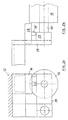
- a cone warping machine has an essential component a warping drum 11 by one, not shown Warping drum drive is rotatable. At one end the warping drum 11 has one that can be seen in FIG. 1.3 Cone 19, which the support of the tapes wound up Threads 10 is used by the cone warping machine Coils of a creel, not shown, run in.
- the Threads 10 form a thread sheet which is guided by a thread guide 13 are arranged on bandwidth and guided over a measuring roller 20 become.
- the measuring roller 20 is rotated by the thread sheet 10, so that it is possible to measure the thread length. Of the measuring roller 20 passes the thread sheet with partial wrap a guide roller 21 to the warping drum 11.
- the threads 10 of the thread cluster are knotted in bundles and attached Not shown hangers of the drum 11 attached.
- the rotary driven warping drum 11 then pulls the Threads 10 from the bobbin of the creel and winds them on.
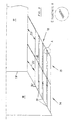
- the threads 10 are wound up in strips according to FIG. 3.
- the threads of a tape are superimposed in many layers wound, with a parallelogram cross-section the bands result, e.g. of volume 14.
- This cross section reached, the first band 14 of the cone 19 of the The warping drum is supported in its axial direction.
- To the out 3 shows parallelogram-shaped cross section of the To reach the first bands 14, the take-up points of the Threads on the warping drum 11 or on the wound thread layers be axially displaced. This is done by appropriate Relative movements between the warping drum 11 and one the Schrriet 13 or the measuring roller 20 and the deflection roller 21 supporting support 12.
- This relative movement parallel to the warping drum is the so-called support feed, for example by a feed drive, not shown is generated, for example by a servo motor that is support-resistant and in a floor rail or a tooth rail of the stationary machine frame shown schematically in Fig.1 17 engages.
- the support feed takes into account the Cone angle and proportional to the increase during winding Winding thickness. While the cone angle is a fixed size and taken into account accordingly when determining the support advance , the increasing winding thickness must be measured be recorded. This is done with a regulating roller 15, which is practically bandwidth and rotatably mounted on the support 12. The regulating roller 15 is on the warping drum 11 at the start of winding employed, the cone beginning 19 'the output or Zero position determined. Builds according to the thread specifics the winding 16 moves faster or slower and must accordingly the support feed may be larger or smaller. For example, if the yarn is thick, the winding thickness increases faster and the feed or the axial adjustment of the Guide roller 15 in mm per degree of angle or per drum revolution must be bigger.
- the regulating roller 15 is vertical in a manner not shown adjustable to the axis of the drum 11 and is before winding start move against the warping drum. If the warping drum 11 is rotated, the winding 16 builds up in layers on.
- a Measurement phase 23 carried out, for example, over 100 Rotations of the warping drum 11 extends.
- the measurement phase 23 so the tape is scanned under contact pressure and if the set pressure is exceeded, the servo motor an axis-parallel movement and at the same time one radial movement triggered as long, and in small Steps until the set pressure is available again.
- an average value is determined, that is average adjustment path per warp drum revolution and thus one medium feed. This corresponds to the feed rate during of the copying following the measuring phase 23 applied becomes.
- the measurement phase 23 extends only over a comparatively low winding thickness. It is therefore possible that the measurement is not accurate enough, and that in the course of the further Winding up the first tape changes the pressure of the Rule roller 15 on the roll 16 result. The consequence would be one wrong winding structure. It is therefore intended to reduce the pressure of the Control roller 15 on the reel 16.
- the roller is articulated on the support 12.
- the Articulation takes place with a swivel arm 39 at each end of the Guide roller 15, which allows relative movements to support 12.
- Each swivel arm 19 supports one end 15 'of a control roller axis the regulating roller 15 with a bearing 23.
- a pressure pin 18 'of a pressure sensor 18 is supported, which in turn is fixed to the machine frame. Shift of the regulating roller 15 and the swivel arm 39 therefore lead to an adjustment of the push pin 18 'and consequently to a measured value of the pressure sensor 18.
- Adjustment of the pressure of the regulating roller 15 on the winding 16 is done in that the Regulating roller 15 with the support 12 against the warping drum 11 is pushed until the predetermined pressure is reached becomes. Because the measured value of the pressure sensor is continuously available it is possible to monitor it continuously and change if necessary. This can happen during the The first band is warmed, for example, by that the support advance is corrected within the copying process becomes.
- the method during the measurement phase 23 is based on Fig.4 explained.
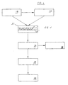
- 4 shows the pressure sensor 18 as a block, which forwards its measurement result to a control device 27.
- the curve v1 of this pressure in Depicted schematically for example as a function of time.
- the pressure v1 fluctuates around an average value v2, which as thread-specific printing from a data memory 27 'of the control device 27 is specified.
- the control device 24 acts on a memory 29 for the Measuring phase with the feed per revolution of the warping drum 11.
- the control device 24 also contains the data on the winding speed, to warp length, to bandwidth, to the number of to be wound tapes and thread tension.
- the method is further winding the first volume after the measurement phase.
- the control device 27 gives the averaged feed from the measuring phase continuously to the control device 24. From there the servo motor 25 is actuated, which in turn shifts the support 12.
- the pressure sensor 18 continuously transmits measured values v1 to the control device 27. As soon as these values v1 from thread-specific pressure transmitted to the data memory 27 ' in the + / - tolerance threshold will be exceeded the averaged feed from the measuring phase is changed as long as until v1 again runs within the tolerance thresholds of v2.
- the correction of the support advance is made directly via the control device 24 'on the servo motor 25.
- the control device 24 causes the new feed in one Memory 30 is stored for the copying phase of the first tape becomes. Such corrections are repeated as necessary carried out.
- 3 shows copying phases 32, in each of which Feed changes are made, if in the measuring phase 23 determined feed is not suitable, the roller 15 in Keep tolerance of v2.
- a copying phase follows the measuring phase 32, during which the regulating roller 15 accordingly v2 or corresponding to that obtained during the measurement phase 23, mean value v2 ', not shown, is withdrawn and presses accordingly on the winding 16. It follows a finer gradation of the right flank of the first volume, which was represented by a straight flank section 33.
- the copying takes place of the second band 15, which is explained in Fig.6.
- the support feed is controlled by the memories 29.30.
- the memory 29 controls the support feed exactly as this is recorded for the measurement phase 23 of the first tape and saved.
- the memory 30 takes over Control of the support feed via the control unit 24 and the servo motor 25. Accordingly, in the second Volume 15 Changes in the support feed, as in the further Winding up the first tape 14 after the measurement phase 23 were detained.
- the other tapes are also corresponding sharpened, both according to the values of in the pressure phase 23 occurring pressure changes, as well as accordingly those that occurred during the copy phase of the first tape Feed changes in the change phases 31.
- FIG. 3 there is also a second one in addition to the first one Volume 15 shown.
- This second volume 15 and any other Tapes are copied according to the first tape 14. It So there are tapes with winding portions 23 ', as in the Measurement phase 23 are constructed. Until the completion of the complete second tape 15 is then wound as well Rest of the first tape after the measurement phase 23. Also when copying of the tape 15 and any other tapes can Pressure monitoring. There are additional, not shown change phases 31 in the second volume 15, which in the following tapes can be adopted.
- the feedrate is expediently corrected in steps. For example, an emerging pressure increase in the following drum rotation in the smallest Steps reduced by 10 angular degrees of drum rotation.
- the number of steps depends on the increase in pressure or from the decrease in pressure. Small pressure changes are required fewer steps, larger pressure changes require many Steps.
- the number of steps can also be one Go out of drum rotation. With gradual feed correction the tape is particularly clean, because large jumps in feed are avoided.
- control device 24 no feed has been entered, but that the off Start of winding build-up pressure to exceed the minus tolerance leads and a corresponding feed change caused, which also takes into account the cone angle.
- the method can also be carried out so that the Control device 24 has a fixed feed, which already comes into effect during the measurement phase 23.
- feed is based on empirical values or is calculated by depending on thread-specific data it is determined how thread coloring, rotation etc.
Landscapes
- Engineering & Computer Science (AREA)
- Textile Engineering (AREA)
- Warping, Beaming, Or Leasing (AREA)
- Preliminary Treatment Of Fibers (AREA)
- Treatment Of Fiber Materials (AREA)
- Winding Of Webs (AREA)
- Winding Filamentary Materials (AREA)
- Spinning Or Twisting Of Yarns (AREA)
Description
- Fig.1
- eine schematische Seitenansicht der Konusschärmaschine im Bereich ihres Supports,
- Fig.2a
- eine vergrößerte Seitenansicht im Bereich der Walze,
- Fig.2b
- eine gegenüber Fig.2a um 90 Winkelgrad gedrehte Ansicht,
- Fig.3
- eine schematische Teilansicht zweier auf eine Schärtrommel gewickelter Bänder,
- Fig.4
- eine Blockbilddarstellung zur Erläuterung des Verfahrens während der Meßphase,
- Fig.5
- eine Blockbilddarstellung zur Erläuterung des Verfahrens während des Kopierens des ersten Bandes,
- Fig.6
- eine Blockbilddarstellung zur Erläuterung des Verfahrens während der Kopierphase des zweiten und aller weiteren Bänder, und
- Fig.7
- eine Blockbilddarstellung zur Erläuterung des Verfahrens mit zusätzliche Beeinflussung des Wickels mittels Beeinflussung der Fadenzugkraft.
Claims (10)
- Verfahren zum Schären mit einer Konusschärmaschine, die Fäden (10) bandweise auf eine Schärtrommel (11) aufwikkelt, bei dem ein Support (12) für ein Fadenleitriet (13) entsprechend der anwachsenden Wickeldicke und vorbestimmter Schärdaten relativ zur Schärtrommel (11) von einem Vorschubantrieb parallel verschoben wird, wobei das erste Band (14) während einer Meßphase (23) von einer Walze (15) unter Anpreßdruck abgetastet und der abgetastete Verstellweg in Abhängigkeit von der Anzahl der Umdrehungen der Schärtrommel (11) registriert wird und wobei die Walze nach der Meßphase (23) beim weiteren Aufwickeln entsprechend einem mit der Meßphase (23) gewonnenen Mittelwert (v2') zurückgenommen wird und auf den Wickel (16) drückt, dadurch gekennzeichnet, daß der Druck der Walze (15) auf den Wickel (16) während der Meßphase (23) und beim weiteren Aufwickeln und Kopieren fortlaufend meßtechnisch überwacht wird und im Falle einer Abweichung des Überwachungsergebnisses von einem vorbestimmten Sollwert eine Korrektur des Supportvorschubs erfolgt.
- Verfahren nach Anspruch 1, dadurch gekennzeichnet, daß die Meßphase mit einem Druck-Sollwert gestartet wird, der in Abhängigkeit von Kenngrößen der aufzuwikkelnden Fäden (10) ausgewählt wird.
- Verfahren nach Anspruch 1 oder 2, dadurch gekennzeichnet, daß für die Meßphase ein Vorschub bestimmt wird, dessen Größe von Kenngrößen der aufzuwickelnden Fäden (10) ausgewählt wird.
- Verfahren nach einem der Ansprüche 1 bis 3, dadurch gekennzeichnet, daß die Korrektur des Supportvorschubs auch beim Kopieren von auf das erste Band (14) folgenden Bändern (z.B. 15) erfolgt.
- Verfahren nach einem der Ansprüche 1 bis 4, dadurch gekennzeichnet, daß die Korrektur des Supportvorschubs im Falle einer Druckzunahme oder einer Druckabnahme schrittweise über die Trommeldrehung verteilt erfolgt.
- Verfahren nach einem der Ansprüche 1 bis 5, dadurch gekennzeichnet, daß kurzzeitig auftretende Druckänderungen während der Meßphase (23) und/oder während des Kopierens bei der Gewinnung des Mittelwerts und/oder bei dem Überwachen des Drucks unberücksichtigt bleiben.
- Verfahren nach einem der Ansprüche 1 bis 6, dadurch gekennzeichnet, daß die während der Meßphase (23) auftretenden Vorschubveränderungen, die in Abhängigkeit von der Anzahl der Umdrehungen der Schärtrommel (11) registriert wurden, in Folgebändern kopiert werden.
- Verfahren nach einem der Ansprüche 1 bis 7, dadurch gekennzeichnet, daß das erste Band (14) mit konstanter Fadenzugkraft aufgewickelt wird, und beim Kopieren ab dem zweiten Band (15) eine Beeinflussung der Fadenzugkraft der aufgewickelten Fäden (10) anstelle oder in Ergänzung einer Korrektur des Supportvorschubs erfolgt.
- Konusschärmaschine zur Durchführung des Verfahrens nach einem der Ansprüche 1 bis 8, mit einem ein Fadenleitriet (13) tragenden Support (12), der an einem Maschinengestell (17) parallel zu einer Schärtrommel (11) verstellbar ist, mit einem von einer Steuereinrichtung (24) steuerbaren motorischen Vorschubantrieb zur Erzeugung von dem Wickeldickenzuwachs entsprechenden Relativbewegungen zwischen der Schärtrommel (11) und dem Support (12), mit einer den Wickelumfang mit Druck abtastenden Walze (15), deren Verstellweg in Abhängigkeit von der Anzahl der Umdrehungen der Schärtrommel (11) mit der Steuereinrichtung speicherbar ist, dadurch gekennzeichnet, daß die Walze (15) an mindestens einem Drucksensor (18) abgestützt ist, der die Steuereinrichtung (24) während der Meßphase (28) und beim weiteren Aufwickeln und Kopieren beaufschlagt, welche die Walze (15) im Falle eines Abweichens des gemessenen Drucks von einem vorbestimmten Sollwert im Korrektursinn steuert, wobei die Walze (15) mit einem Servomotor gegen den Wickel (16) gedrückt ist.
- Konusschärmaschine nach Anspruch 9, dadurch gekennzeichnet, daß die Walze (15) an einem Schwenkarm gelagert ist.
Applications Claiming Priority (3)
| Application Number | Priority Date | Filing Date | Title |
|---|---|---|---|
| DE19646087 | 1996-11-08 | ||
| DE19646087A DE19646087A1 (de) | 1996-11-08 | 1996-11-08 | Verfahren und Vorrichtung zum Schären mit einer Konusschärmaschine |
| PCT/EP1997/006157 WO1998021388A1 (de) | 1996-11-08 | 1997-11-06 | Verfahren und vorrichtung zum schären mit einer konusschärmaschine |
Publications (2)
| Publication Number | Publication Date |
|---|---|
| EP0937165A1 EP0937165A1 (de) | 1999-08-25 |
| EP0937165B1 true EP0937165B1 (de) | 2003-03-05 |
Family
ID=7811029
Family Applications (1)
| Application Number | Title | Priority Date | Filing Date |
|---|---|---|---|
| EP97948893A Expired - Lifetime EP0937165B1 (de) | 1996-11-08 | 1997-11-06 | Verfahren und vorrichtung zum schären mit einer konusschärmaschine |
Country Status (9)
| Country | Link |
|---|---|
| US (1) | US6195856B1 (de) |
| EP (1) | EP0937165B1 (de) |
| CN (1) | CN1100902C (de) |
| BR (1) | BR9712919A (de) |
| DE (2) | DE19646087A1 (de) |
| ES (1) | ES2193411T3 (de) |
| PT (1) | PT937165E (de) |
| TR (1) | TR199900996T2 (de) |
| WO (1) | WO1998021388A1 (de) |
Families Citing this family (11)
| Publication number | Priority date | Publication date | Assignee | Title |
|---|---|---|---|---|
| TR200000031T1 (tr) * | 1998-05-07 | 2000-11-21 | Sucker-Müller-Hacoba Gmbh & Co. | Koni kesitli bir eğirme makinesi ile eğirme için yöntem ve cihaz. |
| DE59910664D1 (de) * | 1999-07-16 | 2004-11-04 | Benninger Zell Gmbh | Verfahren und Hilfsvorrichtung zum Einlesen von Fäden in Führungsorgane einer Behandlungsvorrichtung zur Behandlung der Fäden und eine solche Behandlungsvorrichtung |
| DE10355732B4 (de) * | 2003-11-28 | 2007-11-29 | Karl Mayer Textilmaschinenfabrik Gmbh | Schärverfahren |
| DE102004052735A1 (de) * | 2004-10-30 | 2006-05-04 | Moenus Textilmaschinen Gmbh | Verfahren zum Zetteln und Zettelvorrichtung |
| DE102005033524A1 (de) * | 2005-06-22 | 2006-12-28 | H.K.O. Isolier- Und Textiltechnik Gmbh | Bandscheranlage und Verfahren zur Kettbaumherstellung |
| US9896786B2 (en) * | 2012-08-23 | 2018-02-20 | Columbia Insurance Company | Systems and methods for improving and controlling yarn texture |
| US9951445B2 (en) * | 2012-08-23 | 2018-04-24 | Columbia Insurance Company | Systems and methods for improving and controlling yarn texture |
| JP2017036140A (ja) * | 2015-08-12 | 2017-02-16 | 村田機械株式会社 | 糸監視装置及び糸巻取機 |
| CN107523914B (zh) * | 2017-09-08 | 2019-05-21 | 江西诚鑫实业有限公司 | 一种分条整经机的控制方法 |
| CN109612624A (zh) * | 2018-11-28 | 2019-04-12 | 西安理工大学 | 一种回转窑底部托轮径向力多点检测方法 |
| CN117867714B (zh) * | 2024-03-11 | 2024-05-07 | 常州市鑫尚光电科技有限公司 | 一种整经机导纱功能的变位调节装置 |
Family Cites Families (14)
| Publication number | Priority date | Publication date | Assignee | Title |
|---|---|---|---|---|
| US2398232A (en) * | 1944-04-24 | 1946-04-09 | Lambach Fritz | Warping or beaming machine |
| US2635321A (en) * | 1949-11-23 | 1953-04-21 | American Viscose Corp | Winding apparatus |
| US3429016A (en) * | 1967-01-18 | 1969-02-25 | Westinghouse Electric Corp | Warp tension control means |
| DE2510517C3 (de) * | 1975-03-11 | 1979-06-13 | Hacoba Textilmaschinen Gmbh & Co Kg, 5600 Wuppertal | Verfahren und Vorrichtung zum Schären von Fäden |
| CH606545A5 (de) * | 1976-04-23 | 1978-11-15 | Benninger Ag Maschf | |
| DE2631573C3 (de) * | 1976-07-14 | 1986-07-10 | Hacoba Textilmaschinen Gmbh & Co Kg, 5600 Wuppertal | Verfahren und Vorrichtung zum Schären von Fäden |
| CH603849A5 (de) * | 1976-12-17 | 1978-08-31 | Benninger Ag Maschf | |
| CH661061A5 (de) * | 1983-10-06 | 1987-06-30 | Benninger Ag Maschf | Verfahren zum steuern des schaerschlittens einer schaermaschine und schaermaschine. |
| CH669409A5 (de) * | 1986-02-27 | 1989-03-15 | Benninger Ag Maschf | |
| CH675261A5 (de) | 1987-05-14 | 1990-09-14 | Benninger Ag Maschf | |
| US4989798A (en) * | 1988-11-07 | 1991-02-05 | Appalachian Electronic Instruments, Inc. | High speed precision yarn winding system |
| DE9110397U1 (de) * | 1990-08-24 | 1991-10-10 | Benninger AG, Uzwil, St. Gallen | Vorrichtung zum Messen der Wickeldicke von Fäden |
| DE9110361U1 (de) | 1991-08-22 | 1991-12-05 | Hacoba Textilmaschinen Gmbh & Co Kg, 5600 Wuppertal | Konusschärmaschine |
| DE4304956C2 (de) | 1993-02-18 | 1998-09-24 | Mayer Textilmaschf | Verfahren und Vorrichtung zum Schären von Fäden |
-
1996
- 1996-11-08 DE DE19646087A patent/DE19646087A1/de not_active Withdrawn
-
1997
- 1997-11-06 EP EP97948893A patent/EP0937165B1/de not_active Expired - Lifetime
- 1997-11-06 DE DE59709455T patent/DE59709455D1/de not_active Expired - Fee Related
- 1997-11-06 ES ES97948893T patent/ES2193411T3/es not_active Expired - Lifetime
- 1997-11-06 US US09/297,590 patent/US6195856B1/en not_active Expired - Fee Related
- 1997-11-06 PT PT97948893T patent/PT937165E/pt unknown
- 1997-11-06 CN CN97199466A patent/CN1100902C/zh not_active Expired - Lifetime
- 1997-11-06 WO PCT/EP1997/006157 patent/WO1998021388A1/de not_active Ceased
- 1997-11-06 BR BR9712919-4A patent/BR9712919A/pt not_active IP Right Cessation
- 1997-11-06 TR TR1999/00996T patent/TR199900996T2/xx unknown
Also Published As
| Publication number | Publication date |
|---|---|
| DE59709455D1 (de) | 2003-04-10 |
| EP0937165A1 (de) | 1999-08-25 |
| ES2193411T3 (es) | 2003-11-01 |
| US6195856B1 (en) | 2001-03-06 |
| TR199900996T2 (xx) | 1999-07-21 |
| CN1100902C (zh) | 2003-02-05 |
| CN1236406A (zh) | 1999-11-24 |
| WO1998021388A1 (de) | 1998-05-22 |
| BR9712919A (pt) | 1999-12-07 |
| DE19646087A1 (de) | 1998-05-14 |
| PT937165E (pt) | 2003-07-31 |
Similar Documents
| Publication | Publication Date | Title |
|---|---|---|
| DE69131211T2 (de) | Aufbau eines Fadenwickels | |
| DE60127645T2 (de) | Vorrichtung zum Steuern der Warenaufwicklung bei Webmaschinen | |
| DE2715988C2 (de) | Vorrichtung zum Steuern des Bandauftrages bei einer Schärmaschine | |
| DE3706872C2 (de) | ||
| EP0937165B1 (de) | Verfahren und vorrichtung zum schären mit einer konusschärmaschine | |
| DE69405197T2 (de) | Methode zum Aufwickeln von Fäden | |
| DE2510517B2 (de) | Verfahren und Vorrichtung zum Schären von Fäden | |
| DE3702293C2 (de) | ||
| EP0994975B1 (de) | Verfahren und vorrichtung zum schären mit einer konusschärmaschine | |
| EP2810908B1 (de) | Verfahren zum Einstellen einer Drehwinkelstellung eines eine Spulenhülse drehbeweglich halternden Spulenrahmens und Spulen herstellende Textilmaschine mit mehreren Spulstellen | |
| DE3432276C2 (de) | ||
| DE2631573C3 (de) | Verfahren und Vorrichtung zum Schären von Fäden | |
| EP0696332B1 (de) | Verfahren zum schären von fäden | |
| EP2302116B1 (de) | Verfahren zum Erzeugen einer Musterkette und Musterkettenschärmaschine | |
| EP1460156A2 (de) | Konusschärmaschine und Verfahren zum Herstellen einer Kette auf einer Konusschärmaschine | |
| DE3812045A1 (de) | Verfahren zur steuerung einer schaermaschine und schaermaschine zur durchfuehrung des verfahrens | |
| DE4430566A1 (de) | Verfahren zum Aufwickeln eines Fadens einer geradzylindrischen Kreuzspule | |
| EP2810907B1 (de) | Verfahren zum Einstellen einer Drehwinkelstellung eines eine Spule drehbeweglich halternden Spulenrahmens und Spulen herstellende Textilmaschine mit mehreren Spulstellen | |
| EP2169098A1 (de) | Verfahren zum Betrieb einer Konusschärmaschine und Konusschärmaschine | |
| EP0931189B1 (de) | Verfahren und vorrichtung zum bewickeln eines kettbaums | |
| DE2829833C2 (de) | Vorrichtung und Verfahren zum Ermitteln und Einstellen der richtigen Konusneigung an einer Schärmaschine mit verstellbarem Konus | |
| DE19820019A1 (de) | Verfahren und Vorrichtung zum Schären mit einer Konusschärmaschine | |
| DE7422784U (de) | Vorrichtung zum aufspulen von garnen | |
| DE9200855U1 (de) | Konusschärmaschine |
Legal Events
| Date | Code | Title | Description |
|---|---|---|---|
| PUAI | Public reference made under article 153(3) epc to a published international application that has entered the european phase |
Free format text: ORIGINAL CODE: 0009012 |
|
| 17P | Request for examination filed |
Effective date: 19990522 |
|
| AK | Designated contracting states |
Kind code of ref document: A1 Designated state(s): BE CH DE ES FR GB IT LI PT |
|
| 17Q | First examination report despatched |
Effective date: 20010508 |
|
| GRAG | Despatch of communication of intention to grant |
Free format text: ORIGINAL CODE: EPIDOS AGRA |
|
| RAP1 | Party data changed (applicant data changed or rights of an application transferred) |
Owner name: SUCKER-MUELLER-HACOBA GMBH & CO. |
|
| GRAG | Despatch of communication of intention to grant |
Free format text: ORIGINAL CODE: EPIDOS AGRA |
|
| GRAH | Despatch of communication of intention to grant a patent |
Free format text: ORIGINAL CODE: EPIDOS IGRA |
|
| GRAH | Despatch of communication of intention to grant a patent |
Free format text: ORIGINAL CODE: EPIDOS IGRA |
|
| GRAA | (expected) grant |
Free format text: ORIGINAL CODE: 0009210 |
|
| AK | Designated contracting states |
Designated state(s): BE CH DE ES FR GB IT LI PT |
|
| REG | Reference to a national code |
Ref country code: GB Ref legal event code: FG4D Free format text: NOT ENGLISH |
|
| REG | Reference to a national code |
Ref country code: CH Ref legal event code: EP |
|
| GBT | Gb: translation of ep patent filed (gb section 77(6)(a)/1977) |
Effective date: 20030305 |
|
| REF | Corresponds to: |
Ref document number: 59709455 Country of ref document: DE Date of ref document: 20030410 Kind code of ref document: P |
|
| REG | Reference to a national code |
Ref country code: CH Ref legal event code: NV Representative=s name: DR. LUSUARDI AG |
|
| ET | Fr: translation filed | ||
| REG | Reference to a national code |
Ref country code: ES Ref legal event code: FG2A Ref document number: 2193411 Country of ref document: ES Kind code of ref document: T3 |
|
| PLBE | No opposition filed within time limit |
Free format text: ORIGINAL CODE: 0009261 |
|
| STAA | Information on the status of an ep patent application or granted ep patent |
Free format text: STATUS: NO OPPOSITION FILED WITHIN TIME LIMIT |
|
| 26N | No opposition filed |
Effective date: 20031208 |
|
| REG | Reference to a national code |
Ref country code: CH Ref legal event code: PUE Owner name: MOENUS TEXTILMASCHINEN GMBH Free format text: SUCKER-MUELLER-HACOBA GMBH & CO.#BLUMENBERGER STRASSE 143-145#41061 MOENCHENGLADBACH (DE) -TRANSFER TO- MOENUS TEXTILMASCHINEN GMBH#HEINRICH-HERTZ-STRASSE 28#07552 GERA (DE) |
|
| PGFP | Annual fee paid to national office [announced via postgrant information from national office to epo] |
Ref country code: GB Payment date: 20051109 Year of fee payment: 9 |
|
| PGFP | Annual fee paid to national office [announced via postgrant information from national office to epo] |
Ref country code: ES Payment date: 20051114 Year of fee payment: 9 |
|
| PGFP | Annual fee paid to national office [announced via postgrant information from national office to epo] |
Ref country code: PT Payment date: 20051115 Year of fee payment: 9 |
|
| PGFP | Annual fee paid to national office [announced via postgrant information from national office to epo] |
Ref country code: FR Payment date: 20051128 Year of fee payment: 9 |
|
| PG25 | Lapsed in a contracting state [announced via postgrant information from national office to epo] |
Ref country code: PT Free format text: LAPSE BECAUSE OF NON-PAYMENT OF DUE FEES Effective date: 20070507 |
|
| REG | Reference to a national code |
Ref country code: PT Ref legal event code: MM4A Free format text: LAPSE DUE TO NON-PAYMENT OF FEES Effective date: 20070507 |
|
| GBPC | Gb: european patent ceased through non-payment of renewal fee |
Effective date: 20061106 |
|
| REG | Reference to a national code |
Ref country code: FR Ref legal event code: ST Effective date: 20070731 |
|
| REG | Reference to a national code |
Ref country code: CH Ref legal event code: PFA Owner name: MOENUS TEXTILMASCHINEN GMBH Free format text: MOENUS TEXTILMASCHINEN GMBH#HEINRICH-HERTZ-STRASSE 28#07552 GERA (DE) -TRANSFER TO- MOENUS TEXTILMASCHINEN GMBH#HEINRICH-HERTZ-STRASSE 28#07552 GERA (DE) |
|
| PG25 | Lapsed in a contracting state [announced via postgrant information from national office to epo] |
Ref country code: GB Free format text: LAPSE BECAUSE OF NON-PAYMENT OF DUE FEES Effective date: 20061106 |
|
| REG | Reference to a national code |
Ref country code: ES Ref legal event code: FD2A Effective date: 20061107 |
|
| PG25 | Lapsed in a contracting state [announced via postgrant information from national office to epo] |
Ref country code: FR Free format text: LAPSE BECAUSE OF NON-PAYMENT OF DUE FEES Effective date: 20061130 Ref country code: ES Free format text: LAPSE BECAUSE OF NON-PAYMENT OF DUE FEES Effective date: 20061107 |
|
| REG | Reference to a national code |
Ref country code: CH Ref legal event code: PUE Owner name: SUCKER TEXTILMASCHINEN GMBH Free format text: TEXMAG-ABWICKLUNGSGESELLSCHAFT MBH#HEINRICH-HERTZ-STRASSE 28#07552 GERA (DE) -TRANSFER TO- SUCKER TEXTILMASCHINEN GMBH#BLUMENBERGER STRASSE 143-145#41061 MOENCHENGLADBACH (DE) Ref country code: CH Ref legal event code: PFA Owner name: TEXMAG-ABWICKLUNGSGESELLSCHAFT MBH Free format text: MOENUS TEXTILMASCHINEN GMBH#HEINRICH-HERTZ-STRASSE 28#07552 GERA (DE) -TRANSFER TO- TEXMAG-ABWICKLUNGSGESELLSCHAFT MBH#HEINRICH-HERTZ-STRASSE 28#07552 GERA (DE) |
|
| PGFP | Annual fee paid to national office [announced via postgrant information from national office to epo] |
Ref country code: DE Payment date: 20081115 Year of fee payment: 12 Ref country code: CH Payment date: 20081124 Year of fee payment: 12 |
|
| PGFP | Annual fee paid to national office [announced via postgrant information from national office to epo] |
Ref country code: BE Payment date: 20091123 Year of fee payment: 13 |
|
| REG | Reference to a national code |
Ref country code: CH Ref legal event code: PL |
|
| PG25 | Lapsed in a contracting state [announced via postgrant information from national office to epo] |
Ref country code: LI Free format text: LAPSE BECAUSE OF NON-PAYMENT OF DUE FEES Effective date: 20091130 Ref country code: CH Free format text: LAPSE BECAUSE OF NON-PAYMENT OF DUE FEES Effective date: 20091130 |
|
| PG25 | Lapsed in a contracting state [announced via postgrant information from national office to epo] |
Ref country code: DE Free format text: LAPSE BECAUSE OF NON-PAYMENT OF DUE FEES Effective date: 20100601 |
|
| BERE | Be: lapsed |
Owner name: SUCKER TEXTILMASCHINEN G.M.B.H. Effective date: 20101130 |
|
| PG25 | Lapsed in a contracting state [announced via postgrant information from national office to epo] |
Ref country code: BE Free format text: LAPSE BECAUSE OF NON-PAYMENT OF DUE FEES Effective date: 20101130 |
|
| PGFP | Annual fee paid to national office [announced via postgrant information from national office to epo] |
Ref country code: IT Payment date: 20161124 Year of fee payment: 20 |