EP0936423A2 - Verflüssiger mit integriertem Sammler für Kühlmittel - Google Patents
Verflüssiger mit integriertem Sammler für Kühlmittel Download PDFInfo
- Publication number
- EP0936423A2 EP0936423A2 EP99300851A EP99300851A EP0936423A2 EP 0936423 A2 EP0936423 A2 EP 0936423A2 EP 99300851 A EP99300851 A EP 99300851A EP 99300851 A EP99300851 A EP 99300851A EP 0936423 A2 EP0936423 A2 EP 0936423A2
- Authority
- EP
- European Patent Office
- Prior art keywords
- receiver
- refrigerant
- headers
- condenser
- header
- Prior art date
- Legal status (The legal status is an assumption and is not a legal conclusion. Google has not performed a legal analysis and makes no representation as to the accuracy of the status listed.)
- Withdrawn
Links
Images


Classifications
-
- F—MECHANICAL ENGINEERING; LIGHTING; HEATING; WEAPONS; BLASTING
- F28—HEAT EXCHANGE IN GENERAL
- F28D—HEAT-EXCHANGE APPARATUS, NOT PROVIDED FOR IN ANOTHER SUBCLASS, IN WHICH THE HEAT-EXCHANGE MEDIA DO NOT COME INTO DIRECT CONTACT
- F28D1/00—Heat-exchange apparatus having stationary conduit assemblies for one heat-exchange medium only, the media being in contact with different sides of the conduit wall, in which the other heat-exchange medium is a large body of fluid, e.g. domestic or motor car radiators
- F28D1/02—Heat-exchange apparatus having stationary conduit assemblies for one heat-exchange medium only, the media being in contact with different sides of the conduit wall, in which the other heat-exchange medium is a large body of fluid, e.g. domestic or motor car radiators with heat-exchange conduits immersed in the body of fluid
- F28D1/04—Heat-exchange apparatus having stationary conduit assemblies for one heat-exchange medium only, the media being in contact with different sides of the conduit wall, in which the other heat-exchange medium is a large body of fluid, e.g. domestic or motor car radiators with heat-exchange conduits immersed in the body of fluid with tubular conduits
- F28D1/053—Heat-exchange apparatus having stationary conduit assemblies for one heat-exchange medium only, the media being in contact with different sides of the conduit wall, in which the other heat-exchange medium is a large body of fluid, e.g. domestic or motor car radiators with heat-exchange conduits immersed in the body of fluid with tubular conduits the conduits being straight
- F28D1/0535—Heat-exchange apparatus having stationary conduit assemblies for one heat-exchange medium only, the media being in contact with different sides of the conduit wall, in which the other heat-exchange medium is a large body of fluid, e.g. domestic or motor car radiators with heat-exchange conduits immersed in the body of fluid with tubular conduits the conduits being straight the conduits having a non-circular cross-section
- F28D1/05366—Assemblies of conduits connected to common headers, e.g. core type radiators
- F28D1/05375—Assemblies of conduits connected to common headers, e.g. core type radiators with particular pattern of flow, e.g. change of flow direction
-
- F—MECHANICAL ENGINEERING; LIGHTING; HEATING; WEAPONS; BLASTING
- F25—REFRIGERATION OR COOLING; COMBINED HEATING AND REFRIGERATION SYSTEMS; HEAT PUMP SYSTEMS; MANUFACTURE OR STORAGE OF ICE; LIQUEFACTION SOLIDIFICATION OF GASES
- F25B—REFRIGERATION MACHINES, PLANTS OR SYSTEMS; COMBINED HEATING AND REFRIGERATION SYSTEMS; HEAT PUMP SYSTEMS
- F25B39/00—Evaporators; Condensers
- F25B39/04—Condensers
-
- F—MECHANICAL ENGINEERING; LIGHTING; HEATING; WEAPONS; BLASTING
- F25—REFRIGERATION OR COOLING; COMBINED HEATING AND REFRIGERATION SYSTEMS; HEAT PUMP SYSTEMS; MANUFACTURE OR STORAGE OF ICE; LIQUEFACTION SOLIDIFICATION OF GASES
- F25B—REFRIGERATION MACHINES, PLANTS OR SYSTEMS; COMBINED HEATING AND REFRIGERATION SYSTEMS; HEAT PUMP SYSTEMS
- F25B40/00—Subcoolers, desuperheaters or superheaters
- F25B40/02—Subcoolers
-
- F—MECHANICAL ENGINEERING; LIGHTING; HEATING; WEAPONS; BLASTING
- F28—HEAT EXCHANGE IN GENERAL
- F28F—DETAILS OF HEAT-EXCHANGE AND HEAT-TRANSFER APPARATUS, OF GENERAL APPLICATION
- F28F9/00—Casings; Header boxes; Auxiliary supports for elements; Auxiliary members within casings
- F28F9/02—Header boxes; End plates
- F28F9/026—Header boxes; End plates with static flow control means, e.g. with means for uniformly distributing heat exchange media into conduits
- F28F9/028—Header boxes; End plates with static flow control means, e.g. with means for uniformly distributing heat exchange media into conduits by using inserts for modifying the pattern of flow inside the header box, e.g. by using flow restrictors or permeable bodies or blocks with channels
-
- F—MECHANICAL ENGINEERING; LIGHTING; HEATING; WEAPONS; BLASTING
- F25—REFRIGERATION OR COOLING; COMBINED HEATING AND REFRIGERATION SYSTEMS; HEAT PUMP SYSTEMS; MANUFACTURE OR STORAGE OF ICE; LIQUEFACTION SOLIDIFICATION OF GASES
- F25B—REFRIGERATION MACHINES, PLANTS OR SYSTEMS; COMBINED HEATING AND REFRIGERATION SYSTEMS; HEAT PUMP SYSTEMS
- F25B2339/00—Details of evaporators; Details of condensers
- F25B2339/04—Details of condensers
- F25B2339/044—Condensers with an integrated receiver
- F25B2339/0446—Condensers with an integrated receiver characterised by the refrigerant tubes connecting the header of the condenser to the receiver; Inlet or outlet connections to receiver
-
- F—MECHANICAL ENGINEERING; LIGHTING; HEATING; WEAPONS; BLASTING
- F25—REFRIGERATION OR COOLING; COMBINED HEATING AND REFRIGERATION SYSTEMS; HEAT PUMP SYSTEMS; MANUFACTURE OR STORAGE OF ICE; LIQUEFACTION SOLIDIFICATION OF GASES
- F25B—REFRIGERATION MACHINES, PLANTS OR SYSTEMS; COMBINED HEATING AND REFRIGERATION SYSTEMS; HEAT PUMP SYSTEMS
- F25B2400/00—General features or devices for refrigeration machines, plants or systems, combined heating and refrigeration systems or heat-pump systems, i.e. not limited to a particular subgroup of F25B
- F25B2400/02—Centrifugal separation of gas, liquid or oil
-
- F—MECHANICAL ENGINEERING; LIGHTING; HEATING; WEAPONS; BLASTING
- F25—REFRIGERATION OR COOLING; COMBINED HEATING AND REFRIGERATION SYSTEMS; HEAT PUMP SYSTEMS; MANUFACTURE OR STORAGE OF ICE; LIQUEFACTION SOLIDIFICATION OF GASES
- F25B—REFRIGERATION MACHINES, PLANTS OR SYSTEMS; COMBINED HEATING AND REFRIGERATION SYSTEMS; HEAT PUMP SYSTEMS
- F25B2500/00—Problems to be solved
- F25B2500/01—Geometry problems, e.g. for reducing size
-
- F—MECHANICAL ENGINEERING; LIGHTING; HEATING; WEAPONS; BLASTING
- F28—HEAT EXCHANGE IN GENERAL
- F28D—HEAT-EXCHANGE APPARATUS, NOT PROVIDED FOR IN ANOTHER SUBCLASS, IN WHICH THE HEAT-EXCHANGE MEDIA DO NOT COME INTO DIRECT CONTACT
- F28D21/00—Heat-exchange apparatus not covered by any of the groups F28D1/00 - F28D20/00
- F28D2021/0019—Other heat exchangers for particular applications; Heat exchange systems not otherwise provided for
- F28D2021/0068—Other heat exchangers for particular applications; Heat exchange systems not otherwise provided for for refrigerant cycles
- F28D2021/007—Condensers
Definitions
- This invention relates to refrigeration systems such as air conditioning systems, and more specifically, to an integral receiver/condenser useful in such systems.
- Vapor compression refrigeration systems conventionally employ a condenser which receives a refrigerant in the vapor phase under relatively high pressure from a compressor.
- the condenser is operative to condense the refrigerant vapor to the liquid phase for ultimate transmittal to an evaporator whereat the refrigerant evaporates. Heat from the ambient is rejected to the refrigerant where it is absorbed as the latent heat of vaporization as the refrigerant evaporates.
- the now vaporized refrigerant is then directed to the compressor to be recycled through the system.
- Such systems include a so-called receiver which is intended to receive liquid refrigerant from the condenser before it is transmitted to the evaporator.
- the primary purpose of the receiver is to assure that all refrigerant passed to an expansion device upstream of the evaporator is in the liquid phase. This means that the refrigerant quality is low and its enthalpy is also low to increase the evaporator's ability to absorb heat as the refrigerant evaporates.
- the receiver acts as a reservoir for excess liquid refrigerant to assure that only liquid is fed to the expansion device in spite of system changes typically caused by the operation of the compressor. For example, in an automotive air conditioning system, the compressor is frequently stopped and started. Furthermore, when the engine to which the compressor is typically mechanically coupled is accelerating, compressor speed may also change, causing a change in the pressure at its inlet which in turn affects the flow rate of refrigerant in the system.
- receivers may also be provided with a means for filtering the refrigerant as well as for drying the refrigerant to assure its purity, thereby avoiding inefficient operation.
- CFC 12 is thought to degrade the protection ozone layer surrounding the earth.
- Other refrigerants such as HFC 134a, while less damaging of the ozone layer, are thought to contribute to the so-called greenhouse effect which may be responsible for global warming.
- the compressor is driven by the vehicle engine, it cannot be hermetically sealed as in residential or commercial air conditioning units. As a consequence, there is the potential for escape of the refrigerant through compressor seals with the resulting deleterious effects on the environment. Thus, refrigerant charge volume is of substantial concern.
- the present invention is directed to overcoming one or more of the above problems.
- the improved receiver/condenser will be employed in an automotive air conditioning system.
- a condenser for a refrigerant includes two spaced, non-horizontal, elongated headers.
- Tube slots are in the facing sides of the headers with the tube slots in one header being generally aligned with the tube slots in the other head.
- a plurality of tubes extend between the headers with their ends in corresponding ones of the slots to establish a plurality of hydraulically parallel flow paths between the headers.
- At least one partition is located at each of the headers for causing refrigerant to make at least two passes, including a first pass and a last pass, through the condenser.
- a refrigerant inlet is located in one of the headers and communicates with the first pass.
- a refrigerant outlet is also located in one of the headers and communicates with the last pass.
- An elongated receiver is mounted on one of the headers and has a longitudinal axis. The receiver has a lower liquid outlet connected to an upstream side of the last pass and an upper inlet connected to a downstream side of the first pass. The upper inlet and lower outlet, at their connections to the header on which the receiver is mounted, are separated by one of the partitions.
- the upper inlet is canted with respect to the longitudinal axis of the receiver to induce a vortex flow of refrigerant in the receiver, while according to another embodiment of the invention, the upper inlet is also canted to one side of the longitudinal axis. In a highly preferred embodiment of the invention, the upper inlet is canted upwardly toward the longitudinal axis and is also canted to one side of the longitudinal axis.
- the condenser is provided with elongated headers, tube slots, a plurality of tubes, at least one partition in each header, a refrigerant inlet, a refrigerant outlet and an elongated receiver having an upper inlet and a lower outlet as before.
- a perforate baffle is located within the receiver at a location between the upper inlet and the lower outlet and serves to maintain separation of liquid refrigerant from refrigerant in the vapor phase.
- a detachable cap is provided for the receiver so as to allow the installation of a filter and/or conventional drying material within the receiver.
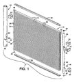
- a condenser generally designated 20 and a receiver, generally designated 22 mounted thereon in substantial abutting relation therewith.
- Tha condenser includes tubular, elongated, vertically oriented headers 24.
- Each header 24 on its side facing the other includes a plurality of tube slots 26 which are aligned with the tube slots 26 in the opposite header.
- a plurality of multiport flattened tubes 28 extend between the headers 24 and have their ends 30 received in sealed relation in corresponding ones of the slots 26.
- the components will be made of aluminum and are bonded together as by brazing.
- Serpentine fins 34 shown only schematically in the figures, extend between adjacent ones of the tubes 28 and, at the sides of the condenser 20, side plates 36.
- tubular headers 24 are sealed as by end plugs 40 which are typically brazed in place.
- the embodiment illustrated is intended to be a two pass condenser and to this end, near its lower end, includes a double slot 42 which receives an imperforate partition or baffle 44.
- the slot 42 and baffle 44 are formed generally in the fashion shown in Figs. 1-6 of commonly assigned United States Letters Patent No. 4,936,381 issued on June 26, 1990 to Alley, the entire disclosure of which is herein incorporated by reference.
- the opposite header 24 includes a similar slot 46 which receives a baffle 48 which is also generally the same as the baffle 44.
- the slots 42 and 46 are at the same location on their respective headers.
- the rightmost header 24 includes an inlet opening 50 to which an inlet fixture 52 is brazed.
- the fixture 52 serves as the point of connection of the condenser into the system and it will be seen that the same is above the baffle 44.
- the rightmost header 24 includes a second opening 54 which in turn receives an outlet fixture 56 which serves as the outlet from the receiver/condenser to the system.
- a mounting fixture 58 may also be brazed to the rightmost header 24.
- a similar fixture 60 may be brazed to the leftmost header 24.
- the receiver 22 is cylindrical and of generally the same length as the headers 24. It is of a larger diameter so as to provide sufficient volume to store the necessary amount of refrigerant as the system requires.
- the receiver 22 As its upper end, the receiver 22 is closed by a threaded cap 62.
- the cap 62 is thus removable and serves as a means whereby, after assembly of the receiver/condenser, a filter and/or a conventional drying material may be introduced into the receiver 22.
- the receiver 22 Near its lower end, the receiver 22 includes an upper refrigerant inlet 64 and a lower refrigerant outlet 66. As illustrated in Fig. 1, the upper inlet 64 and lower outlet 66 are in the form of nipples which may be sealingly received in aligned openings in the leftmost header 24. The arrangement is such that the upper inlet 64 will be above the partition 48 while the lower outlet 66 will be below the partition 48.
- refrigerant may enter through the fixture 52 and be distributed by the header 24 to the tube ends 30 that are above the partition 44 to flow to the leftmost header. Once the refrigerant enters the leftmost header 24, it may exit the same via the upper inlet 64 to the receiver 22. After the mixture of liquid and vapor phase refrigerant is separated within the receiver 22, liquid refrigerant may exit the receiver 22 via the lower outlet to ultimately be returned to the rightmost header 24 via those tubes 28 that are located below the partitions 44 and 48. During this pass, the liquid will be subcooled as desired and ultimately will be returned to the system via the fitting 56.
- the invention is not limited to any specific number of passes although it will always be employed in a condenser having at least two passes.
- the same includes a baffle receiving slot 70 for purposes to be seen.
- FIG. 5 A cylindrical tube defining the receiver 22 is shown at 72, albeit somewhat schematically and its longitudinal axis is designated 74.
- the inlet 64 is canted at an acute angle a with respect to the longitudinal axis 74.
- the inlet 64 is canted upwardly with respect to the axis 74.
- the inlet 64 may be alternatively or additively canted to one side of the longitudinal axis 64 by an angle ⁇ .
- this configuration causes the generation of a vortex of the incoming mixed phase refrigerant.
- the vortex is much the same as that found in a cyclone separator with the higher density liquid refrigerant being centrifugally flung against the interior wall of the receiver 22 to drain under the influence of gravity toward the lower outlet 66.
- the lesser density vaporous refrigerant remains in the receiver 22 until it condenses as a result of heat exchange though the receiver wall or as a result of contact with incoming liquid refrigerant that may be partially subcooled.
- Fig. 7 illustrates one form of a nipple that may be used in making one or both of the upper inlet 64 and lower outlet 66. Specifically, the same is no more than a short section of tube 80 with a peripheral rib 82 about its center. The rib 82 prevents either end of the tube 80 from extending too far into either the leftmost header 24 or the receiver 22.
- flange 84 As an alternative to the use of the tube, conventional T-drilling may be employed as illustrated in Fig. 8 to form a flange 84 extending outwardly from the header 24 to peripherally embrace a somewhat smaller flange 86 in the wall of the receiver 22.
- the flanges 84 and 86 are united and sealed during the brazing operation.
- Fig. 9 illustrates still another form of means by which the receiver 22 may be mounted on the condenser 20.
- a short section of tube 90 is employed and the same is provided with a generally central, peripheral rib 92 having the same function as the rib 82.
- an upturned lip or projection 95 is provided on that end 94 of the tube 90 that is to enter the receiver 22.
- the lip 95 may be made to direct incoming mixed refrigerant at the angle ⁇ or at the angle ⁇ , or both.
- the same may simply be skewed somewhat to provide either or both of the angles ⁇ and ⁇ by appropriately directioning the bores in the receiver 22 and the header 24 in which the same is received.
- Fig. 10 shows still another form of a means by which the receiver 22 may be mounted on the condenser 20.
- a saddle-like mounting block 96 is employed and the same includes first and second semicylindrical recesses 97 and 98.
- the recess 97 is of the same diameter as the outside diameter of the header 24 while the recess 98 is of the same diameter as the outside diameter of the receiver 22.
- Interconnecting recesses 98 and 97 is a bore 99.
- the tube 80 may done away with entirely with the ends of the bore 99 respectively aligned with the openings in the receiver 22 and the header 24 that are normally occupied by the tube 80. When the assembly is brazed together, braze metal will provide a seal around the ends of the bore 99 to make the junction fluid tight.
- Fig. 11 shows still another form of a means by which the receiver 22 may be mounted on the condenser.
- a saddle like mounting block 100 is employed and again, the same has oppositely directed recesses 101 and 102 which are semicylindrical and which are dimensioned just as the recesses 97 and 98.
- a bore 103 connects the recesses 101 and 102 just as the bore 99.
- a short length of tube 104 is inserted in the end of the bore 103 opening to the recess 102.
- the tube 104 is sized so as to enter the opening in the receiver 22 that would otherwise be occupied by the tube 80.
- the bore 99 is generally formed to intersect the longitudinal axis 74 of the receiver 22 at mutually perpendicular right angles, that may or may not be true of the bore 103.
- the bore 103 may be angled such that the tube 104 will enter the receiver 22 at an angle canted with respect to the longitudinal axis 74, the angle being either the angle a (Fig. 5) or the angle ⁇ (Fig. 6) or both to provide a desired vortex action as explained previously.
- a slot 70 is provided in the receiver 22.
- the slot 70 is a double slot much like that shown in the previously identified Alley patent and is intended to receive a baffle configured generally in the form illustrated by Alley.
- Fig. 12 illustrates a preferred form of the baffle and the same is seen to include a generally circular plate 106 with opposed, L-shaped notches 108 in its opposite sides.
- the baffle disclosed by Alley spaces the notches 108 a distance approximately equal to the inside diameter of the tube, in the baffle illustrated in Fig. 12, the long sides 110 of the notches 108 are spaced a distance less than the internal diameter of the receiver 22 so as to leave a pair of elongated openings 112 between the inner tube wall 114 of the receiver 22 and the long sides 110.
- the openings 112 serve as drain holes whereby liquid refrigerant may drain from that part of the receiver 24 above the baffle 106 toward the lower outlet 66 while the main body of the baffle plate 106 serves to isolate any turbulence occurring in the vicinity of the upper inlet 64 from the liquid adjacent the lower outlet 66.
- Fig. 13 illustrates another form of the baffle as being made of a generally circular plate 115 having two L-shaped notches 11 6 cut in the sides thereof for the purposes mentioned by Alley.
- the plate 115 is provided with a plurality of elongated slots 117 near its periphery.
- the slots 117 are arcuate. Just as in the Fig. 12 embodiment, they serve as drain holes whereby liquid refrigerant may drain from that part of the receiver 24 above the baffle 11 5 toward the lower outlet 66 while the main body of the baffle plate 115 serves to isolate any turbulence occurring in the vicinity of the upper inlet 64 from the liquid adjacent the lower outlet 66.
- Fig. 14 illustrates another form of a baffle which again includes a generally circular plate 118 provided with L-shaped cutouts 119 in opposite sides for the same purpose as disclosed by Alley.
- a generally central, circular aperture 120 is provided to serve the same functions as the slots 117.
- a plate 121 is employed and is provided with L-shaped notches 122 like those illustrated at 116 and 119.
- a tab 124 is displaced from the body of the plate 121 to leave an opening 126.
- the opening 126 serves as a drain hole much like the slots 117 or the aperture 120.
- the tab 124 may be oriented to be in the path of the incoming stream, that is, in the discharge path of, for example, the opening defined by the flanges 84,86 or the end of the tube 80 within the receiver to provide a desired deflection of the incoming mixed refrigerant stream at the angles ⁇ or ⁇ or both.
- Fig. 16 the tube 80 is employed as the upper inlet 64 and as can be seen, is canted in the manner mentioned in connection with Figs. 5 and 6.
- the vortex of the incoming refrigerant is illustrated by an upwardly spiraling arrow 130 which illustrates the path taken by the liquid refrigerant.
- Arrows 132 and dots 134 illustrate the path taken by the gaseous refrigerant.
- the baffle 100 acts to effectively segregate any turbulence as a result of the incoming stream or that may be generated by movement of the receiver 22, as when in a vehicle, from the lower outlet 66.
- the baffle 100 may be omitted while in others, the baffle 100 may be retained and the canting of the upper inlet 64 omitted.
- Fig. 17 Still another advantage of the construction of the invention is illustrated in Fig. 17. It will be appreciated that by appropriately locating the holes or openings for the connection of the receiver 22 to the header 24, the receiver 22 may be located in any of a plurality of positions spaced as many as 180° about the header 24 as illustrated by the positions shown at 22, 22' or 22". Thus, depending upon the available space at a given installation, the position of the receiver with respect to the body of the condenser may be varied substantially to accommodate special spatial requirements.
Landscapes
- Engineering & Computer Science (AREA)
- Physics & Mathematics (AREA)
- Thermal Sciences (AREA)
- Mechanical Engineering (AREA)
- General Engineering & Computer Science (AREA)
- Air-Conditioning For Vehicles (AREA)
- Heat-Exchange Devices With Radiators And Conduit Assemblies (AREA)
- Cooling Or The Like Of Semiconductors Or Solid State Devices (AREA)
Applications Claiming Priority (2)
| Application Number | Priority Date | Filing Date | Title |
|---|---|---|---|
| US20210 | 1998-02-06 | ||
| US09/020,210 US5934102A (en) | 1998-02-06 | 1998-02-06 | Integral receiver/condenser for a refrigerant |
Publications (2)
| Publication Number | Publication Date |
|---|---|
| EP0936423A2 true EP0936423A2 (de) | 1999-08-18 |
| EP0936423A3 EP0936423A3 (de) | 2000-04-05 |
Family
ID=21797331
Family Applications (1)
| Application Number | Title | Priority Date | Filing Date |
|---|---|---|---|
| EP99300851A Withdrawn EP0936423A3 (de) | 1998-02-06 | 1999-02-04 | Verflüssiger mit integriertem Sammler für Kühlmittel |
Country Status (12)
| Country | Link |
|---|---|
| US (1) | US5934102A (de) |
| EP (1) | EP0936423A3 (de) |
| JP (1) | JPH11270928A (de) |
| KR (1) | KR19990072444A (de) |
| CN (1) | CN1154819C (de) |
| AR (2) | AR014541A1 (de) |
| AU (1) | AU741643B2 (de) |
| BR (1) | BR9907624A (de) |
| CA (1) | CA2261251A1 (de) |
| MY (1) | MY126432A (de) |
| TW (1) | TW484004B (de) |
| ZA (1) | ZA99892B (de) |
Cited By (9)
| Publication number | Priority date | Publication date | Assignee | Title |
|---|---|---|---|---|
| EP1310748A3 (de) * | 2001-11-08 | 2004-01-02 | Behr GmbH & Co. | Wärmetauscher |
| WO2004025196A1 (de) * | 2002-08-31 | 2004-03-25 | Behr Gmbh & Co. | Kältemittelkondensator, insbesondere für kratfahrzeug-klimaanlagen |
| WO2004025195A1 (de) * | 2002-08-31 | 2004-03-25 | Behr Gmbh & Co. | Sammler für ein kältemittel, wärmetauscher, kältemittelkreislauf und verfahren zur herstellung eines sammlers |
| EP1426712A1 (de) * | 2002-11-22 | 2004-06-09 | Mituhiro Kanao | Kühlgerät mit Wirbelverflüssiger |
| EP1584875A1 (de) * | 2004-04-08 | 2005-10-12 | Delphi Technologies, Inc. | Verflüssiger mit integriertem Trocknersammler und Verfahren zu dessen Herstellung |
| FR2887619A1 (fr) * | 2005-06-28 | 2006-12-29 | Valeo Systemes Thermiques | Echangeur de chaleur muni d'un reservoir et procede de fabrication d'un tel echangeur |
| EP1916488A1 (de) * | 2006-10-27 | 2008-04-30 | Behr France Hambach S.A.R.L. | Wärmeübertrager, insbesondere Kondensator |
| DE102011080673A1 (de) * | 2011-08-09 | 2013-02-14 | Behr Gmbh & Co. Kg | Kältemittelkondensatorbaugruppe |
| EP3062042A1 (de) | 2015-02-27 | 2016-08-31 | MAHLE International GmbH | Fluidsammler |
Families Citing this family (24)
| Publication number | Priority date | Publication date | Assignee | Title |
|---|---|---|---|---|
| JP2000227265A (ja) * | 1999-02-03 | 2000-08-15 | Denso Corp | 受液器一体型冷媒凝縮器 |
| JP4147709B2 (ja) * | 1999-03-05 | 2008-09-10 | 株式会社デンソー | 冷媒凝縮器 |
| JP4041634B2 (ja) * | 1999-03-30 | 2008-01-30 | カルソニックカンセイ株式会社 | 凝縮器 |
| US6125652A (en) * | 1999-08-27 | 2000-10-03 | Ardco, Inc. | Apparatus for minimizing refrigerant usage |
| FR2799821B1 (fr) * | 1999-09-28 | 2002-03-29 | Valeo Thermique Moteur Sa | Condenseur comprenant un reservoir fixe de maniere amovible et etanche sur une embase |
| US6223556B1 (en) * | 1999-11-24 | 2001-05-01 | Modine Manufacturing Company | Integrated parallel flow condenser receiver assembly |
| JP2002263055A (ja) * | 2001-03-12 | 2002-09-17 | Olympus Optical Co Ltd | 内視鏡先端フード |
| KR100441086B1 (ko) * | 2001-08-02 | 2004-07-19 | 엘지전자 주식회사 | 펌프다운을 위한 용기가 구비된 공기 조화기 |
| US6793121B2 (en) * | 2002-03-12 | 2004-09-21 | Newfield Technology Corporation | Clasp having a flange to couple a heat exchanger to a device in a cooling system |
| US6622517B1 (en) | 2002-06-25 | 2003-09-23 | Visteon Global Technologies, Inc. | Condenser assembly having readily varied volumetrics |
| FR2845747B1 (fr) * | 2002-10-15 | 2005-08-19 | Advanced Automation | Dispositif de transmission et application a un dispositif de dosage |
| US6694773B1 (en) * | 2003-01-29 | 2004-02-24 | Calsonickansei North America, Inc. | Condenser system with nondetachably coupled receiver |
| US6981389B2 (en) | 2003-12-12 | 2006-01-03 | Calsonickansei North America, Inc. | Receiver and service cartridge for a condenser system |
| US7003978B2 (en) | 2003-12-12 | 2006-02-28 | Calsonickansei North America, Inc. | Service cartridge for a receiver in a condenser system |
| US7093461B2 (en) * | 2004-03-16 | 2006-08-22 | Hutchinson Fts, Inc. | Receiver-dryer for improving refrigeration cycle efficiency |
| PL1831619T3 (pl) * | 2004-12-24 | 2018-11-30 | Arçelik Anonim Sirketi | Urządzenie chłodzące |
| US20070251256A1 (en) * | 2006-03-20 | 2007-11-01 | Pham Hung M | Flash tank design and control for heat pumps |
| KR20100021194A (ko) * | 2008-08-14 | 2010-02-24 | 기아자동차주식회사 | 공조기용 냉매 여과장치 |
| US9581397B2 (en) * | 2011-12-29 | 2017-02-28 | Mahle International Gmbh | Heat exchanger assembly having a distributor tube retainer tab |
| KR101462176B1 (ko) * | 2013-07-16 | 2014-11-21 | 삼성전자주식회사 | 열교환기 |
| DE112015004953T5 (de) | 2014-10-31 | 2017-08-24 | Modine Manufacturing Company | Kühlmodul und clausius-rankine-prozess- abwärmerückgewinnungssystem |
| DE102016001607A1 (de) | 2015-05-01 | 2016-11-03 | Modine Manufacturing Company | Flüssigkeit-zu-Kältemittel-Wärmetauscher und Verfahren zum betrieb desselben |
| CN109931727A (zh) | 2017-12-18 | 2019-06-25 | 杭州三花研究院有限公司 | 一种集液器以及具有该集液器的换热装置 |
| CN116164557B (zh) * | 2023-03-02 | 2024-08-02 | 江苏凯乐汽车部件科技有限公司 | 一种汽车散热器及其制造工艺 |
Citations (1)
| Publication number | Priority date | Publication date | Assignee | Title |
|---|---|---|---|---|
| US5546761A (en) | 1994-02-16 | 1996-08-20 | Nippondenso Co., Ltd. | Receiver-integrated refrigerant condenser |
Family Cites Families (31)
| Publication number | Priority date | Publication date | Assignee | Title |
|---|---|---|---|---|
| US4019337A (en) * | 1974-10-23 | 1977-04-26 | Zearfoss Jr Elmer W | Refrigeration apparatus and method |
| US4651540A (en) * | 1986-03-21 | 1987-03-24 | Tecumseh Products Company | Suction accumulator including an entrance baffle |
| JPH0540308Y2 (de) * | 1987-02-06 | 1993-10-13 | ||
| US4936381A (en) * | 1988-12-27 | 1990-06-26 | Modine Manufacturing Company | Baffle for tubular header |
| JPH0740943Y2 (ja) * | 1989-02-03 | 1995-09-20 | サンデン株式会社 | 受液部内蔵型凝縮器 |
| US4972683A (en) * | 1989-09-01 | 1990-11-27 | Blackstone Corporation | Condenser with receiver/subcooler |
| JP3081941B2 (ja) * | 1990-08-23 | 2000-08-28 | 株式会社ゼクセル | レシーバタンク一体型コンデンサ |
| US5224358A (en) * | 1990-10-04 | 1993-07-06 | Nippondenso Co., Ltd. | Refrigerating apparatus and modulator |
| JP3044395B2 (ja) * | 1990-12-28 | 2000-05-22 | 株式会社ゼクセル | レシーバドライヤ一体型コンデンサ |
| US5201195A (en) * | 1992-04-27 | 1993-04-13 | General Motors Corporation | Bi-flow receiver/dehydrator for refrigeration system |
| US5233842A (en) * | 1992-07-01 | 1993-08-10 | Thermo King Corporation | Accumulator for refrigeration system |
| US5289697A (en) * | 1992-10-28 | 1994-03-01 | Eaton Corporation | Refrigerant receiver/drier |
| JP3301169B2 (ja) * | 1992-11-06 | 2002-07-15 | 株式会社デンソー | 冷凍装置 |
| DE4245046C8 (de) * | 1992-11-18 | 2008-08-21 | Behr Gmbh & Co. Kg | Kondensator für eine Klimaanlage eines Fahrzeuges |
| JPH06236006A (ja) * | 1993-02-10 | 1994-08-23 | Fuji Photo Film Co Ltd | ハロゲン化銀カラー写真感光材料 |
| DE4319293C2 (de) * | 1993-06-10 | 1998-08-27 | Behr Gmbh & Co | Kondensator für eine Klimaanlage |
| FR2707742B1 (fr) * | 1993-07-15 | 1995-10-06 | Behr Gmbh & Co | Condenseur d'une installation de climatisation d'un véhicule. |
| FR2709344B1 (fr) * | 1993-08-27 | 1995-10-13 | Valeo Thermique Moteur Sa | Condenseur pour installation de climatisation de véhicule automobile. |
| US5426956A (en) * | 1993-11-04 | 1995-06-27 | Phillippe; Gary E. | Refrigerant system efficiency amplifying apparatus |
| JP3355844B2 (ja) * | 1994-02-16 | 2002-12-09 | 株式会社デンソー | 受液器一体型冷媒凝縮器 |
| US5582027A (en) * | 1994-03-29 | 1996-12-10 | Nippondenso Co., Ltd. | Modulator integrated type refrigerant condenser |
| JP3243924B2 (ja) * | 1994-04-01 | 2002-01-07 | 株式会社デンソー | 冷媒凝縮器 |
| JPH07332806A (ja) * | 1994-04-12 | 1995-12-22 | Nippondenso Co Ltd | 冷凍装置 |
| US5435149A (en) * | 1994-04-28 | 1995-07-25 | Frigoscandia Equipment Aktiebolag | Refrigeration system |
| DE4421834A1 (de) * | 1994-06-22 | 1996-01-04 | Behr Gmbh & Co | Einsatz für einen Kondensator einer Klimaanlage eines Fahrzeuges |
| JP3561957B2 (ja) * | 1994-07-22 | 2004-09-08 | 株式会社デンソー | 受液器一体型冷媒凝縮器 |
| JP3371627B2 (ja) * | 1995-07-20 | 2003-01-27 | 株式会社デンソー | 車両用熱交換装置 |
| JPH09145199A (ja) * | 1995-11-22 | 1997-06-06 | Calsonic Corp | リキッドタンクを備えたコンデンサ |
| FR2749647B1 (fr) * | 1996-06-05 | 1998-08-07 | Valeo Thermique Moteur Sa | Condenseur a reservoir separe pour installation de climatisation, notamment de vehicule automobile |
| JPH102692A (ja) * | 1996-06-14 | 1998-01-06 | Zexel Corp | 熱交換器のブラケット構造 |
| JPH10122705A (ja) * | 1996-10-14 | 1998-05-15 | Calsonic Corp | リキッドタンク付コンデンサ |
-
1998
- 1998-02-06 US US09/020,210 patent/US5934102A/en not_active Expired - Fee Related
-
1999
- 1999-02-04 ZA ZA9900892A patent/ZA99892B/xx unknown
- 1999-02-04 EP EP99300851A patent/EP0936423A3/de not_active Withdrawn
- 1999-02-05 MY MYPI99000400A patent/MY126432A/en unknown
- 1999-02-05 CA CA002261251A patent/CA2261251A1/en not_active Abandoned
- 1999-02-05 KR KR1019990003916A patent/KR19990072444A/ko not_active Application Discontinuation
- 1999-02-05 AR ARP990100485A patent/AR014541A1/es active IP Right Grant
- 1999-02-05 CN CNB991056264A patent/CN1154819C/zh not_active Expired - Fee Related
- 1999-02-05 BR BR9907624-1A patent/BR9907624A/pt active Search and Examination
- 1999-02-08 JP JP11029826A patent/JPH11270928A/ja active Pending
- 1999-02-08 AU AU16355/99A patent/AU741643B2/en not_active Ceased
- 1999-02-10 TW TW088101833A patent/TW484004B/zh not_active IP Right Cessation
- 1999-11-24 AR ARP990105986A patent/AR043079A2/es unknown
Patent Citations (1)
| Publication number | Priority date | Publication date | Assignee | Title |
|---|---|---|---|---|
| US5546761A (en) | 1994-02-16 | 1996-08-20 | Nippondenso Co., Ltd. | Receiver-integrated refrigerant condenser |
Cited By (13)
| Publication number | Priority date | Publication date | Assignee | Title |
|---|---|---|---|---|
| EP1310748A3 (de) * | 2001-11-08 | 2004-01-02 | Behr GmbH & Co. | Wärmetauscher |
| US7334429B2 (en) | 2002-08-31 | 2008-02-26 | Behr Gmbh & Co. Kg | Refrigerant condenser for motor vehicle air-conditioning systems |
| WO2004025196A1 (de) * | 2002-08-31 | 2004-03-25 | Behr Gmbh & Co. | Kältemittelkondensator, insbesondere für kratfahrzeug-klimaanlagen |
| WO2004025195A1 (de) * | 2002-08-31 | 2004-03-25 | Behr Gmbh & Co. | Sammler für ein kältemittel, wärmetauscher, kältemittelkreislauf und verfahren zur herstellung eines sammlers |
| US7428825B2 (en) | 2002-08-31 | 2008-09-30 | Behr Gmbh & Co. Kg | Manifold for cooling agent, heat exchanger, cooling agent closed circuit and method for producing a manifold |
| EP1426712A1 (de) * | 2002-11-22 | 2004-06-09 | Mituhiro Kanao | Kühlgerät mit Wirbelverflüssiger |
| US7131293B2 (en) | 2004-04-08 | 2006-11-07 | Delphi Technologies, Inc. | Dryer integrated condenser of a refrigerating system and a method of assembling the same |
| EP1584875A1 (de) * | 2004-04-08 | 2005-10-12 | Delphi Technologies, Inc. | Verflüssiger mit integriertem Trocknersammler und Verfahren zu dessen Herstellung |
| FR2887619A1 (fr) * | 2005-06-28 | 2006-12-29 | Valeo Systemes Thermiques | Echangeur de chaleur muni d'un reservoir et procede de fabrication d'un tel echangeur |
| EP1916488A1 (de) * | 2006-10-27 | 2008-04-30 | Behr France Hambach S.A.R.L. | Wärmeübertrager, insbesondere Kondensator |
| DE102011080673A1 (de) * | 2011-08-09 | 2013-02-14 | Behr Gmbh & Co. Kg | Kältemittelkondensatorbaugruppe |
| DE102011080673B4 (de) | 2011-08-09 | 2024-01-11 | Mahle International Gmbh | Kältemittelkondensatorbaugruppe |
| EP3062042A1 (de) | 2015-02-27 | 2016-08-31 | MAHLE International GmbH | Fluidsammler |
Also Published As
| Publication number | Publication date |
|---|---|
| KR19990072444A (ko) | 1999-09-27 |
| CN1232160A (zh) | 1999-10-20 |
| JPH11270928A (ja) | 1999-10-05 |
| CN1154819C (zh) | 2004-06-23 |
| BR9907624A (pt) | 2000-10-17 |
| ZA99892B (en) | 1999-08-05 |
| EP0936423A3 (de) | 2000-04-05 |
| AU741643B2 (en) | 2001-12-06 |
| AR043079A2 (es) | 2005-07-20 |
| US5934102A (en) | 1999-08-10 |
| AU1635599A (en) | 1999-08-26 |
| TW484004B (en) | 2002-04-21 |
| AR014541A1 (es) | 2001-02-28 |
| CA2261251A1 (en) | 1999-08-06 |
| MY126432A (en) | 2006-09-29 |
Similar Documents
| Publication | Publication Date | Title |
|---|---|---|
| US5934102A (en) | Integral receiver/condenser for a refrigerant | |
| US6223556B1 (en) | Integrated parallel flow condenser receiver assembly | |
| US5875650A (en) | Refrigerant condenser including super-cooling portion | |
| US5592830A (en) | Refrigerant condenser with integral receiver | |
| US5088294A (en) | Condenser with a built-in receiver | |
| US7089760B2 (en) | Air-conditioner | |
| US6260379B1 (en) | Condenser with integral receiver dryer | |
| EP1310749A1 (de) | Sammelbehälter eines kältekreislaufes mit einem mit sammelbehälter versehenem wärmetauscher und verflüssigungseinheit eines kältekreislaufes | |
| US6698235B2 (en) | Refrigerant cycle system having discharge function of gas refrigerant in receiver | |
| US6494059B2 (en) | Receiver tank for use in refrigeration cycle, heat exchanger with said receiver tank, and condensing apparatus for use in refrigeration cycle | |
| JPH06137695A (ja) | 冷凍サイクル | |
| JPH10132425A (ja) | 受液器一体型冷媒凝縮器 | |
| US6341647B1 (en) | Separator-integrated condenser for vehicle air conditioner | |
| US6360560B1 (en) | Condenser with integral receiver dryer | |
| JP3617083B2 (ja) | 受液器一体型冷媒凝縮器 | |
| US20020059806A1 (en) | Refrigeration cycle apparatus | |
| US6318116B1 (en) | Plastic internal accumulator-dehydrator baffle | |
| MXPA99001344A (en) | Condenser / integral receiver for a refrigerator | |
| US6684662B2 (en) | Refrigeration system, and condenser for use in decompressing-tube system | |
| EP1831619B1 (de) | Kühlvorrichtung | |
| US6971251B2 (en) | Integrated condenser/receiver | |
| JP4335428B2 (ja) | アキュムレータ及び冷凍サイクル装置 | |
| JPH0875311A (ja) | 冷凍装置 | |
| JP2001099525A (ja) | 受液器および冷凍サイクル装置 | |
| JP2003161538A (ja) | 冷凍サイクル装置および凝縮器 |
Legal Events
| Date | Code | Title | Description |
|---|---|---|---|
| PUAI | Public reference made under article 153(3) epc to a published international application that has entered the european phase |
Free format text: ORIGINAL CODE: 0009012 |
|
| AK | Designated contracting states |
Kind code of ref document: A2 Designated state(s): AT DE ES FR GB IT NL SE |
|
| AX | Request for extension of the european patent |
Free format text: AL;LT;LV;MK;RO;SI |
|
| PUAL | Search report despatched |
Free format text: ORIGINAL CODE: 0009013 |
|
| AK | Designated contracting states |
Kind code of ref document: A3 Designated state(s): AT BE CH CY DE DK ES FI FR GB GR IE IT LI LU MC NL PT SE |
|
| AX | Request for extension of the european patent |
Free format text: AL;LT;LV;MK;RO;SI |
|
| 17P | Request for examination filed |
Effective date: 20000925 |
|
| AKX | Designation fees paid |
Free format text: AT DE ES FR GB IT NL SE |
|
| 17Q | First examination report despatched |
Effective date: 20020313 |
|
| 17Q | First examination report despatched |
Effective date: 20020313 |
|
| STAA | Information on the status of an ep patent application or granted ep patent |
Free format text: STATUS: THE APPLICATION IS DEEMED TO BE WITHDRAWN |
|
| 18D | Application deemed to be withdrawn |
Effective date: 20071005 |