EP0931697B1 - Leuchte mit Rückstrahler für Fahrzeuge - Google Patents
Leuchte mit Rückstrahler für Fahrzeuge Download PDFInfo
- Publication number
- EP0931697B1 EP0931697B1 EP99101193A EP99101193A EP0931697B1 EP 0931697 B1 EP0931697 B1 EP 0931697B1 EP 99101193 A EP99101193 A EP 99101193A EP 99101193 A EP99101193 A EP 99101193A EP 0931697 B1 EP0931697 B1 EP 0931697B1
- Authority
- EP
- European Patent Office
- Prior art keywords
- reflex reflector
- lighting fixture
- housing
- ornamental plate
- outer lens
- Prior art date
- Legal status (The legal status is an assumption and is not a legal conclusion. Google has not performed a legal analysis and makes no representation as to the accuracy of the status listed.)
- Expired - Lifetime
Links
Images

Classifications
-
- B—PERFORMING OPERATIONS; TRANSPORTING
- B60—VEHICLES IN GENERAL
- B60Q—ARRANGEMENT OF SIGNALLING OR LIGHTING DEVICES, THE MOUNTING OR SUPPORTING THEREOF OR CIRCUITS THEREFOR, FOR VEHICLES IN GENERAL
- B60Q1/00—Arrangement of optical signalling or lighting devices, the mounting or supporting thereof or circuits therefor
- B60Q1/26—Arrangement of optical signalling or lighting devices, the mounting or supporting thereof or circuits therefor the devices being primarily intended to indicate the vehicle, or parts thereof, or to give signals, to other traffic
- B60Q1/28—Arrangement of optical signalling or lighting devices, the mounting or supporting thereof or circuits therefor the devices being primarily intended to indicate the vehicle, or parts thereof, or to give signals, to other traffic for indicating front of vehicle
-
- B—PERFORMING OPERATIONS; TRANSPORTING
- B60—VEHICLES IN GENERAL
- B60Q—ARRANGEMENT OF SIGNALLING OR LIGHTING DEVICES, THE MOUNTING OR SUPPORTING THEREOF OR CIRCUITS THEREFOR, FOR VEHICLES IN GENERAL
- B60Q1/00—Arrangement of optical signalling or lighting devices, the mounting or supporting thereof or circuits therefor
- B60Q1/26—Arrangement of optical signalling or lighting devices, the mounting or supporting thereof or circuits therefor the devices being primarily intended to indicate the vehicle, or parts thereof, or to give signals, to other traffic
-
- F—MECHANICAL ENGINEERING; LIGHTING; HEATING; WEAPONS; BLASTING
- F21—LIGHTING
- F21S—NON-PORTABLE LIGHTING DEVICES; SYSTEMS THEREOF; VEHICLE LIGHTING DEVICES SPECIALLY ADAPTED FOR VEHICLE EXTERIORS
- F21S43/00—Signalling devices specially adapted for vehicle exteriors, e.g. brake lamps, direction indicator lights or reversing lights
- F21S43/30—Signalling devices specially adapted for vehicle exteriors, e.g. brake lamps, direction indicator lights or reversing lights characterised by reflectors
Definitions
- This invention relates to a lighting fixture for vehicles, and more particularly to a lighting fixture of this kind, which has a light body equipped with a reflex reflector for reflecting light irradiated from an oncoming vehicle to the same vehicle.
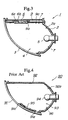
- a reflex reflector 95 Mounted on a rear surface (internal surface) side of the outer lens 91 at a suitable location thereof is a reflex reflector 95 that is formed as a separate member.
- the reflex reflector is connected to the outer lens 91 via a joint portion 91a thereof in one body by means such as ultrasonic welding.
- the reflex reflector 95 is formed, e.g. of a transparent amber resin member.
- the area of the outer lens 91 on which the reflex reflector 95 is mounted has no lens cut so that the function of the reflex reflector 95 is not damaged.
- reference numeral 96 designates a vacuum deposition film formed of aluminum or the like, for imparting a function of reflecting light to the reflecting mirror 92a.
- the reflecting mirror 92a is formed by a composite reflecting surface such that a desired light distribution characteristic of the lighting fixture is obtainable by the reflecting mirror 92 per se. Therefore, the outer lens 91 is made almost plain or transparent without having a lens cut.
- the reflex reflector 95 is mounted on the outer lens 91 in one body, an effective area of the outer lens 91 is reduced by the area of the reflex reflector 95. As a result, the formation of the light distribution characteristic, e.g. as a front turn signal, which is the essential function of the lighting fixture 90, can be rendered difficult.
- a lighting fixture equipped with a reflex reflector, for a vehicle including a transparent outer lens, a housing, a light source, and the reflex reflector, wherein the reflex reflector is provided in an internal surface of the housing at a location at which incident light can be reflected through the outer lens in a predetermined direction, such that a surface of the reflex reflector and the internal surface of the housing are arranged on the same plane.
- the housing is formed of a transparent amber resin member and integrally formed with the reflex reflector, and the housing is subjected to an opaque process except for a region corresponding to the reflex reflector.
- the ornamental plate is formed of a transparent amber resin member and integrally formed with the reflex reflector, and wherein the ornamental plate is subjected to an opaque process except for a region corresponding to the reflex reflector.
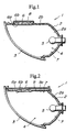
- the RR 6 is integrally molded with the housing 2 at the suitable location thereof, and therefore degraded appearance of the light body 4 caused by forming a separate RR on the plain outer lens 3 by ultrasonic welding can be prevented. Further, when the RR 6 is integrally molded with the housing 2, the internal surface 2b of the housing 2 and the surface 6a of the RR 6 are arranged on the same plane, which prevents optical paths from the light source 5 and the reflecting mirror 2a from being interrupted.
- the ornamental plate 9 is integrally formed with the ornamental plate 9 as described above, the ornamental plate 9 is mounted in the interior of the light body 4, and therefore the reflecting cut surface 6b of the RR 6 is also present within the light body 4. As a result, the reflecting cut surface 6b is free from dust, which dispenses with the rear cover 8 employed in the first embodiment.
- the ornamental plate 9 has an RR-fitting opening 9b formed therein, and is formed of an opaque member separately from the RR 6.
- the RR 6 separately formed of a transparent member is mounted in the RR-fitting opening 9b from a rear side of the ornamental plate 9 by suitable means such as bonding or fitting, and the ornamental plate 9 united with the RR 6 in one body is mounted in the housing 2.
- the surface 6a of the RR 6 and the internal surface 9a of the ornamental plate 9 are arranged on almost the same plane.
- a reflex reflector is mounted on an internal surface of a housing at a location at which incident light can be reflected in a predetermined direction through an outer lens, such that the reflex reflector and the internal surface of the housing are arranged on the same plane.
- the reflex reflector is arranged on an internal surface of an ornamental plate provided along the housing at the same location as mentioned above, such that the reflex reflector and the internal surface of the ornamental plate are arranged on the same plane.
Landscapes
- Engineering & Computer Science (AREA)
- Mechanical Engineering (AREA)
- General Engineering & Computer Science (AREA)
- Non-Portable Lighting Devices Or Systems Thereof (AREA)
- Lighting Device Outwards From Vehicle And Optical Signal (AREA)
Claims (8)
- Mit einem Rückstrahlreflektor (6) ausgestatteter Beleuchtungskörper für ein Fahrzeug, einschließend eine durchsichtige äußere Streuscheibe (3), ein Gehäuse (2), eine Lichtquelle (5) und den Rückstrahlreflektor (6), dadurch gekennzeichnet, dass der Rückstrahlreflektor (6) in einer inneren Oberfläche (2b) des Gehäuses (2) an einer Stelle vorgesehen ist, an der einfallendes Licht durch die äußere Streuscheibe (3) hindurch in eine vorbestimmte Richtung reflektiert werden kann, und zwar so, dass eine Oberfläche (6a; 9a) des Rückstrahlreflektors (6) und die innere Oberfläche (2b) des Gehäuses (2) auf derselben Ebene angeordnet sind.
- Beleuchtungskörper nach Anspruch 1, bei dem das Gehäuse (2) von einem durchsichtigen bernsteinfarbenen Harzelement gebildet wird und als Einheit mit dem Rückstrahlreflektor (6) ausgebildet ist, und bei dem das Gehäuse (2) mit Ausnahme eines dem Rückstrahlreflektor (6) entsprechenden Bereichs (6a) einem Opakisierungsprozess unterzogen worden ist.
- Beleuchtungskörper nach Anspruch 1, bei dem der Rückstrahlreflektor (6) getrennt vom Gehäuse (2) gebildet worden ist.
- Beleuchtungskörper nach Anspruch 1, bei dem eine äußere Oberfläche (6b) des Rückstrahlreflektors (6) mit einem Abdeckelement (8) abgedeckt ist.
- Beleuchtungskörper nach Anspruch 1, weiter umfassend eine in einem Inneren des Gehäuses (2) und entlang des Gehäuses (2) vorgesehene Ornamentplatte (9).
- Beleuchtungskörper nach Anspruch 5, bei dem die Ornamentplatte (9) von einem durchsichtigen bernsteinfarbenen Harzelement gebildet wird und als Einheit mit dem Rückstrahlreflektor (6) ausgebildet ist, und bei dem die Ornamentplatte (9) mit Ausnahme eines dem Rückstrahlreflektor (6) entsprechenden Bereichs einem Opakisierungsprozess unterzogen worden ist.
- Beleuchtungskörper nach Anspruch 5, bei dem der Rückstrahlreflektor (6) getrennt von der Ornamentplatte (9) gebildet worden ist.
- Beleuchtungskörper nach Anspruch 5, bei dem die Ornamentplatte (9) eine darin ausgebildete Befestigungsöffnung (9b) aufweist, wobei der Rückstrahlreflektor (6) mit der Ornamentplatte (9) zu einem Körper vereinigt wird, indem er in der Befestigungsöffnung (9b) montiert wird.
Applications Claiming Priority (2)
| Application Number | Priority Date | Filing Date | Title |
|---|---|---|---|
| JP01148498A JP3337125B2 (ja) | 1998-01-23 | 1998-01-23 | リフレックスリフレクタ付車両用灯具 |
| JP1148498 | 1998-01-23 |
Publications (3)
| Publication Number | Publication Date |
|---|---|
| EP0931697A2 EP0931697A2 (de) | 1999-07-28 |
| EP0931697A3 EP0931697A3 (de) | 2000-09-13 |
| EP0931697B1 true EP0931697B1 (de) | 2004-03-24 |
Family
ID=11779337
Family Applications (1)
| Application Number | Title | Priority Date | Filing Date |
|---|---|---|---|
| EP99101193A Expired - Lifetime EP0931697B1 (de) | 1998-01-23 | 1999-01-22 | Leuchte mit Rückstrahler für Fahrzeuge |
Country Status (4)
| Country | Link |
|---|---|
| US (1) | US6089736A (de) |
| EP (1) | EP0931697B1 (de) |
| JP (1) | JP3337125B2 (de) |
| DE (1) | DE69915716T2 (de) |
Families Citing this family (10)
| Publication number | Priority date | Publication date | Assignee | Title |
|---|---|---|---|---|
| DE19946850A1 (de) * | 1999-09-30 | 2001-04-05 | Hella Kg Hueck & Co | Lichttechnische Einrichtung für Fahrzeuge |
| JP3957963B2 (ja) * | 2000-10-10 | 2007-08-15 | 株式会社小糸製作所 | 車輌用灯具 |
| DE10246945B4 (de) * | 2002-10-08 | 2007-07-19 | Hella Kgaa Hueck & Co. | Fahrzeugleuchte mit Rückstrahlerelement |
| JP2010170891A (ja) * | 2009-01-23 | 2010-08-05 | Stanley Electric Co Ltd | 車両用信号灯具 |
| US8840289B2 (en) * | 2010-04-14 | 2014-09-23 | Toyota Motor Engineering & Manufacturing North America, Inc. | Headlamp light pipe and side marker integration |
| USD670416S1 (en) | 2010-08-23 | 2012-11-06 | Kaper Ii, Inc. | LED light reflector for a vehicle |
| FR2990906B1 (fr) * | 2012-05-25 | 2015-02-27 | Renault Sa | Dispositif de feu de vehicule automobile |
| JP5698291B2 (ja) * | 2013-03-22 | 2015-04-08 | 株式会社小糸製作所 | 車両用灯具 |
| US10648635B1 (en) * | 2018-10-29 | 2020-05-12 | Nissan North America, Inc. | Headlamp structure |
| JP7359076B2 (ja) * | 2020-04-30 | 2023-10-11 | 市光工業株式会社 | 車両用樹脂部品 |
Family Cites Families (9)
| Publication number | Priority date | Publication date | Assignee | Title |
|---|---|---|---|---|
| DE2214161C3 (de) * | 1972-03-23 | 1979-11-08 | Robert Bosch Gmbh, 7000 Stuttgart | Befestigungsanordnung für Blinkleuchten von Kraftfahrzeugen |
| US4912606A (en) * | 1987-10-28 | 1990-03-27 | Koito Manufacturing Co., Ltd. | Vehicle lamp device |
| US5448454A (en) * | 1992-11-30 | 1995-09-05 | Ichikoh Industries, Ltd. | Vehicle lamp device |
| JP2878111B2 (ja) * | 1994-03-09 | 1999-04-05 | 株式会社小糸製作所 | 車両用灯具 |
| JP2787415B2 (ja) * | 1994-03-28 | 1998-08-20 | 株式会社小糸製作所 | 車輌用標識灯 |
| JP3051302B2 (ja) * | 1994-06-08 | 2000-06-12 | 株式会社小糸製作所 | 車両用灯具における係合部材の固定構造 |
| JPH0822707A (ja) * | 1994-07-07 | 1996-01-23 | Koito Mfg Co Ltd | 車両用灯具 |
| JPH08138415A (ja) * | 1994-11-15 | 1996-05-31 | Ichikoh Ind Ltd | 車両用灯具 |
| JPH0924767A (ja) * | 1995-07-11 | 1997-01-28 | Ichikoh Ind Ltd | サイドマーカランプ機能を兼用した車両用灯具 |
-
1998
- 1998-01-23 JP JP01148498A patent/JP3337125B2/ja not_active Expired - Fee Related
-
1999
- 1999-01-22 EP EP99101193A patent/EP0931697B1/de not_active Expired - Lifetime
- 1999-01-22 US US09/235,685 patent/US6089736A/en not_active Expired - Lifetime
- 1999-01-22 DE DE69915716T patent/DE69915716T2/de not_active Expired - Fee Related
Also Published As
| Publication number | Publication date |
|---|---|
| US6089736A (en) | 2000-07-18 |
| EP0931697A2 (de) | 1999-07-28 |
| EP0931697A3 (de) | 2000-09-13 |
| JPH11213710A (ja) | 1999-08-06 |
| JP3337125B2 (ja) | 2002-10-21 |
| DE69915716D1 (de) | 2004-04-29 |
| DE69915716T2 (de) | 2005-02-24 |
Similar Documents
| Publication | Publication Date | Title |
|---|---|---|
| US6107916A (en) | Signal lamp for vehicles | |
| JP2787415B2 (ja) | 車輌用標識灯 | |
| JP2981713B2 (ja) | 車輌用灯具 | |
| EP1442930B1 (de) | Fahrzeugaussenspiegel mit Leuchte | |
| US5373423A (en) | Light for motor vehicle | |
| EP0931697B1 (de) | Leuchte mit Rückstrahler für Fahrzeuge | |
| US6402356B2 (en) | Vehicle lamp | |
| JPH10321015A (ja) | 車輌用灯具 | |
| US7036968B2 (en) | Vehicular lamp with cover including cylindrical lens step portion | |
| GB2242014A (en) | Vehicular signal lamp | |
| JPH0737990Y2 (ja) | 車輌用灯具 | |
| JP2579622Y2 (ja) | 車輌用灯具 | |
| EP0849523A2 (de) | Fahrzeuglampe | |
| JP3740264B2 (ja) | 車輌用灯具 | |
| JPH0612563Y2 (ja) | 車両用灯具 | |
| JP2003257216A (ja) | 車両の外装ランプ | |
| JP2000011726A (ja) | 面発光ランプ装置 | |
| JP2000285722A (ja) | 車両用ランプ構造 | |
| JPH0119284Y2 (de) | ||
| JPH09185908A (ja) | 車両用信号灯具 | |
| JPS5951401A (ja) | 車両用灯体 | |
| JP2558805Y2 (ja) | ポジション付ヘッドランプ | |
| JP3430381B2 (ja) | 補助確認ミラー装置 | |
| JPH0733288Y2 (ja) | 車輌用灯具 | |
| JP2548794Y2 (ja) | サイドターンシグナルランプ |
Legal Events
| Date | Code | Title | Description |
|---|---|---|---|
| PUAI | Public reference made under article 153(3) epc to a published international application that has entered the european phase |
Free format text: ORIGINAL CODE: 0009012 |
|
| AK | Designated contracting states |
Kind code of ref document: A2 Designated state(s): DE FR GB |
|
| AX | Request for extension of the european patent |
Free format text: AL;LT;LV;MK;RO;SI |
|
| PUAL | Search report despatched |
Free format text: ORIGINAL CODE: 0009013 |
|
| AK | Designated contracting states |
Kind code of ref document: A3 Designated state(s): AT BE CH CY DE DK ES FI FR GB GR IE IT LI LU MC NL PT SE |
|
| AX | Request for extension of the european patent |
Free format text: AL;LT;LV;MK;RO;SI |
|
| 17P | Request for examination filed |
Effective date: 20001014 |
|
| AKX | Designation fees paid |
Free format text: DE FR GB |
|
| 17Q | First examination report despatched |
Effective date: 20030120 |
|
| GRAP | Despatch of communication of intention to grant a patent |
Free format text: ORIGINAL CODE: EPIDOSNIGR1 |
|
| GRAS | Grant fee paid |
Free format text: ORIGINAL CODE: EPIDOSNIGR3 |
|
| GRAA | (expected) grant |
Free format text: ORIGINAL CODE: 0009210 |
|
| AK | Designated contracting states |
Kind code of ref document: B1 Designated state(s): DE FR GB |
|
| REG | Reference to a national code |
Ref country code: GB Ref legal event code: FG4D |
|
| REF | Corresponds to: |
Ref document number: 69915716 Country of ref document: DE Date of ref document: 20040429 Kind code of ref document: P |
|
| ET | Fr: translation filed | ||
| PG25 | Lapsed in a contracting state [announced via postgrant information from national office to epo] |
Ref country code: GB Free format text: LAPSE BECAUSE OF NON-PAYMENT OF DUE FEES Effective date: 20050122 |
|
| PLBE | No opposition filed within time limit |
Free format text: ORIGINAL CODE: 0009261 |
|
| STAA | Information on the status of an ep patent application or granted ep patent |
Free format text: STATUS: NO OPPOSITION FILED WITHIN TIME LIMIT |
|
| 26N | No opposition filed |
Effective date: 20041228 |
|
| PG25 | Lapsed in a contracting state [announced via postgrant information from national office to epo] |
Ref country code: DE Free format text: LAPSE BECAUSE OF NON-PAYMENT OF DUE FEES Effective date: 20050802 |
|
| GBPC | Gb: european patent ceased through non-payment of renewal fee |
Effective date: 20050122 |
|
| PG25 | Lapsed in a contracting state [announced via postgrant information from national office to epo] |
Ref country code: FR Free format text: LAPSE BECAUSE OF NON-PAYMENT OF DUE FEES Effective date: 20050930 |
|
| REG | Reference to a national code |
Ref country code: FR Ref legal event code: ST |