EP0928643A2 - Cage de laminoir pour le laminage de fils - Google Patents
Cage de laminoir pour le laminage de fils Download PDFInfo
- Publication number
- EP0928643A2 EP0928643A2 EP98124842A EP98124842A EP0928643A2 EP 0928643 A2 EP0928643 A2 EP 0928643A2 EP 98124842 A EP98124842 A EP 98124842A EP 98124842 A EP98124842 A EP 98124842A EP 0928643 A2 EP0928643 A2 EP 0928643A2
- Authority
- EP
- European Patent Office
- Prior art keywords
- hydraulic cylinder
- shaft
- hydraulic
- roll stand
- chock
- Prior art date
- Legal status (The legal status is an assumption and is not a legal conclusion. Google has not performed a legal analysis and makes no representation as to the accuracy of the status listed.)
- Granted
Links
Images

Classifications
-
- B—PERFORMING OPERATIONS; TRANSPORTING
- B21—MECHANICAL METAL-WORKING WITHOUT ESSENTIALLY REMOVING MATERIAL; PUNCHING METAL
- B21B—ROLLING OF METAL
- B21B13/00—Metal-rolling stands, i.e. an assembly composed of a stand frame, rolls, and accessories
- B21B13/005—Cantilevered roll stands
-
- B—PERFORMING OPERATIONS; TRANSPORTING
- B21—MECHANICAL METAL-WORKING WITHOUT ESSENTIALLY REMOVING MATERIAL; PUNCHING METAL
- B21B—ROLLING OF METAL
- B21B31/00—Rolling stand structures; Mounting, adjusting, or interchanging rolls, roll mountings, or stand frames
- B21B31/16—Adjusting or positioning rolls
- B21B31/20—Adjusting or positioning rolls by moving rolls perpendicularly to roll axis
- B21B31/32—Adjusting or positioning rolls by moving rolls perpendicularly to roll axis by liquid pressure, e.g. hydromechanical adjusting
-
- B—PERFORMING OPERATIONS; TRANSPORTING
- B21—MECHANICAL METAL-WORKING WITHOUT ESSENTIALLY REMOVING MATERIAL; PUNCHING METAL
- B21B—ROLLING OF METAL
- B21B31/00—Rolling stand structures; Mounting, adjusting, or interchanging rolls, roll mountings, or stand frames
- B21B31/16—Adjusting or positioning rolls
- B21B31/20—Adjusting or positioning rolls by moving rolls perpendicularly to roll axis
- B21B31/22—Adjusting or positioning rolls by moving rolls perpendicularly to roll axis mechanically, e.g. by thrust blocks, inserts for removal
- B21B31/26—Adjusting eccentrically-mounted roll bearings
Definitions
- the present invention relates to a roll stand for rolling Wire, with a scaffold frame and at least one chock with a roller-side shaft bearing and a counter shaft bearing, wherein in the shaft bearings a roller support shaft with a shaft axis is mounted, which protrudes beyond the roller-side shaft bearing, so that a roller disc can be attached to the roller support shaft, wherein the roller support shaft with respect to an adjusting unit a further roller support shaft mounted in the roll stand in one Setting direction is adjustable.
- Roll stands of this type are known.
- the task of the present The invention consists in further developing such a rolling stand that in a simple, reliable and inexpensive way exact adjustment of the roller shafts carried out relative to each other can be.
- the roll stand has a hydraulic hydraulic cylinder unit with a hydraulic cylinder and a Has hydraulic piston, the hydraulic cylinder with the Scaffold frame and the hydraulic piston connected to the chock is, so that the roller support shaft by means of the hydraulic jack cylinder unit is employable.
- the hydraulic piston is detachably connected to the chock, is a simple disassembly of the hydraulic hydraulic cylinder unit and / or the chock possible.
- the detachable connection of the hydraulic piston with the chock is structurally particularly simple if the hydraulic piston at least has a fitting bore with a threaded bore of the chock aligns a fitting screw for the Fitting hole is screwed in, which protrudes above the hydraulic piston, and on the dowel screw protruding above the hydraulic piston End of a nut is unscrewed.
- the guide of the roller support shaft by the hydraulic piston is especially accurate when the hydraulic piston is on the chock facing side of the hydraulic cylinder unit, preferably also on the side of the hydraulic cylinder unit facing away from the chock, in a piston bearing, especially a plain bearing, is led.
- a turning of the chock by a parallel to the direction of attack Axis is particularly safely avoided if the chock in the Area of the roller-side shaft bearing transverse to the shaft axis and is mounted free of play transversely to the direction of attack.
- the roll stand has a hydraulic cylinder unit with has a hydraulic cylinder and a hydraulic piston
- the Compensation hydraulic cylinder unit near the counter bearing is arranged and the hydraulic cylinder with the scaffold frame and the hydraulic piston is connected to the chock is open a particularly simple way of tilting the roller disc the roller shaft can be avoided.
- the cost of the roll stand can be reduced if the Compensation hydraulic cylinder unit smaller than the hydraulic hydraulic cylinder unit is trained.
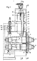
- a roll stand for rolling wire has a frame 1, into which a one-piece chock 2 is installed.
- the chock 2 has a roller-side shaft bearing 3 and a counter shaft bearing 4.
- a roller support shaft 5 is supported with a shaft axis 6.
- the Roller support shaft 5 protrudes beyond the roller-side shaft bearing 3, so that on the roller support shaft 5 a roller disk 7 from the outside is applicable.
- the scaffold frame 1 has two further shaft bearings 8, in which a further roller support shaft 9 is mounted.
- the other too Roller support shaft 9 projects at least on one side over its shaft bearing 8 addition, so that a further roller disc 10 can be applied to it is.
- the roller disks 7, 10 together form a roll gap for a wire to be rolled.
- the roller support shaft 5 is in relation to the further roller support shaft 9 adjustable.
- the roll stand has a hydraulic hydraulic cylinder unit 11 with a hydraulic cylinder 12 and a hydraulic piston 13 on.
- the hydraulic cylinder 12 is with the scaffold frame 1 connected.
- the hydraulic cylinder 12 formed by the scaffold frame 1 and an upper cylinder part 1 '.
- the hydraulic piston 13 is connected to the chock 2. Consequently can by moving the hydraulic piston 13 within the hydraulic cylinder 12 along an adjustment direction 14 the roller support shaft 5 with respect to the further roller supporting shaft 9.
- the hydraulic jack unit 11 is both pressure and position controlled. Thus, not only due to the position control a predetermined roll gap can be approached exactly. Due to the pressure control, the spring deflection can also be compensated of the roll stand when the rolling forces are applied to the Wire can be compensated.
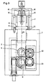
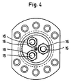
- the hydraulic piston 13 three fitting holes.
- the chock 2 accordingly has three Threaded holes.
- the fitting holes and the threaded holes are in pairs with each other.
- the fitting screws 15 protrude clearly the hydraulic piston 13 out.
- On the protruding ends of the Dowel screws are unscrewed 16 nuts. This is on simple manner of the hydraulic piston 13 releasably with the chock 2 connected.
- the hydraulic piston 13 with the Installation piece 2 connected via three dowel screws 15. But it could a different number of fitting screws 15 can be used. Even a single fitting screw 15 can be sufficient. It is crucial that the hydraulic piston 13 is connected to the chock 2 in such a way that both compressive and tensile forces can be transferred to the chock 2 are.
- the scaffold frame 1 has slide bearings 17 in which the hydraulic piston 13 is performed.
- a plain bearing 17 can be seen on the the chock 2 side of the hydraulic jack unit 11 and a bearing 17 on that facing away from the chock 2 Side of the hydraulic cylinder unit 11 arranged.
- the starting hydraulic cylinder unit 11 is in the vicinity of the roller side Shaft bearing 3 arranged.
- the roll stand is now in the Principle already operational.
- the nip between the roller disks 7, 10 can, however, be adjusted better if the roll stand additionally a hydraulic cylinder unit 18 with a Hydraulic cylinder 19 and a hydraulic piston 20.
- the balancing hydraulic cylinder unit in this case is close to the Counter-shaft bearing 4 arranged.
- the hydraulic cylinder 19 Just like the hydraulic hydraulic cylinder unit 11 is here also the hydraulic cylinder 19 the scaffold frame 1 and the hydraulic piston 20 with the chock 2 connected. Because the balancing hydraulic cylinder unit 18 is less Forces must apply as the hydraulic jack unit 11, can the compensating hydraulic cylinder unit 18 be made smaller be than the starting hydraulic cylinder unit 11. Otherwise Construction, fastening and operation of the hydraulic cylinder unit 18 completely analogous to the hydraulic jack unit 11 be.
- the roller support shafts have 5, 9 between their shaft bearings 3, 4, 8 toothed drums 21.
- the Toothed drum 21 of the roller support shaft 3 meshes directly with a drive pinion 22.
- the drive pinion 22 also meshes with a - not self-propelled - intermediate pinion 23, which in turn combs with the toothed drum 21 of the further roller support shaft 9.
- the further roll supporting shaft is 9 rigidly arranged in the framework 1. It is also sufficient, since the roller shaft 5 is adjustable and it only on the relative position of the roller support shafts 5, 9 arrives at each other. In principle, however, the further roller supporting shaft 9 could also be in one Chock be stored similar to chock 2. In this case the further roller support shaft 9 would of course also be adjustable. There would then be an almost completely symmetrical structure of the Rolling stand.
Landscapes
- Engineering & Computer Science (AREA)
- Mechanical Engineering (AREA)
- Metal Rolling (AREA)
- Reduction Rolling/Reduction Stand/Operation Of Reduction Machine (AREA)
- Rolls And Other Rotary Bodies (AREA)
Applications Claiming Priority (2)
| Application Number | Priority Date | Filing Date | Title |
|---|---|---|---|
| DE19800201A DE19800201A1 (de) | 1998-01-07 | 1998-01-07 | Walzgerüst zum Walzen von Draht |
| DE19800201 | 1998-01-07 |
Publications (3)
| Publication Number | Publication Date |
|---|---|
| EP0928643A2 true EP0928643A2 (fr) | 1999-07-14 |
| EP0928643A3 EP0928643A3 (fr) | 2001-09-26 |
| EP0928643B1 EP0928643B1 (fr) | 2004-08-04 |
Family
ID=7854031
Family Applications (1)
| Application Number | Title | Priority Date | Filing Date |
|---|---|---|---|
| EP98124842A Expired - Lifetime EP0928643B1 (fr) | 1998-01-07 | 1998-12-30 | Cage de laminoir pour le laminage de fils |
Country Status (5)
| Country | Link |
|---|---|
| US (1) | US6035687A (fr) |
| EP (1) | EP0928643B1 (fr) |
| JP (1) | JPH11254011A (fr) |
| AT (1) | ATE272456T1 (fr) |
| DE (2) | DE19800201A1 (fr) |
Cited By (2)
| Publication number | Priority date | Publication date | Assignee | Title |
|---|---|---|---|---|
| DE202018100912U1 (de) | 2018-02-19 | 2019-05-23 | Hpl-Neugnadenfelder Maschinenfabrik Gmbh | Walzgerüst zum Walzen von Draht |
| DE102018103646A1 (de) | 2018-02-19 | 2019-08-22 | Hpl-Neugnadenfelder Maschinenfabrik Gmbh | Walzgerüst und Verfahren zum Walzen von Draht |
Families Citing this family (4)
| Publication number | Priority date | Publication date | Assignee | Title |
|---|---|---|---|---|
| DE102009050710B4 (de) | 2009-10-26 | 2016-08-04 | Sms Group Gmbh | Drahtwalzgerüst mit Einzelantrieb |
| CN103406360B (zh) * | 2013-09-03 | 2016-05-25 | 中冶赛迪工程技术股份有限公司 | 单独传动轧机 |
| CN110421011B (zh) * | 2019-08-16 | 2024-07-05 | 中冶南方工程技术有限公司 | 用于18辊轧机侧支承装置的标定装置及标定方法 |
| CN112845607B (zh) * | 2021-02-04 | 2023-03-28 | 太原理工大学 | 一种超大直径比异步轧机以及板材轧制方法 |
Family Cites Families (9)
| Publication number | Priority date | Publication date | Assignee | Title |
|---|---|---|---|---|
| FR1439920A (fr) * | 1965-02-26 | 1966-05-27 | Spidem Ste Nle | Cage pour laminage en continu de produits métallurgiques de faible largeur |
| US3559432A (en) * | 1968-05-29 | 1971-02-02 | Textron Inc | Roll gap gage control |
| US4413494A (en) * | 1981-02-13 | 1983-11-08 | Morgan Construction Company | Pinch roll system for vertical laying heads |
| JPS58100905A (ja) * | 1981-12-09 | 1983-06-15 | Furukawa Electric Co Ltd:The | 圧延機 |
| US4481800A (en) * | 1982-10-22 | 1984-11-13 | Kennecott Corporation | Cold rolling mill for metal strip |
| JPS6044107A (ja) * | 1983-08-19 | 1985-03-09 | Sakai Jukogyo Kk | 小型圧延機 |
| US5131250A (en) * | 1991-02-08 | 1992-07-21 | The National Machinery Company | Flat die thread roller |
| DE19644351A1 (de) * | 1996-10-25 | 1998-04-30 | Schloemann Siemag Ag | Walzgerüst mit einem Paar zweiseitig gelagerter Walzentragwellen |
| DE19650580A1 (de) * | 1996-12-06 | 1998-06-10 | Schloemann Siemag Ag | Walzgerüst-Exzenterlagerhülsen für Walzentragwellen |
-
1998
- 1998-01-07 DE DE19800201A patent/DE19800201A1/de not_active Withdrawn
- 1998-12-24 JP JP10367775A patent/JPH11254011A/ja not_active Withdrawn
- 1998-12-30 AT AT98124842T patent/ATE272456T1/de not_active IP Right Cessation
- 1998-12-30 EP EP98124842A patent/EP0928643B1/fr not_active Expired - Lifetime
- 1998-12-30 DE DE59811752T patent/DE59811752D1/de not_active Expired - Fee Related
-
1999
- 1999-01-06 US US09/226,821 patent/US6035687A/en not_active Expired - Fee Related
Cited By (4)
| Publication number | Priority date | Publication date | Assignee | Title |
|---|---|---|---|---|
| DE202018100912U1 (de) | 2018-02-19 | 2019-05-23 | Hpl-Neugnadenfelder Maschinenfabrik Gmbh | Walzgerüst zum Walzen von Draht |
| DE102019104212A1 (de) | 2018-02-19 | 2019-08-22 | hpl - Neugnadenfelder Maschinenfabrik GmbH | Walzgerüst und Verfahren zum Walzen von Draht |
| DE102018103646A1 (de) | 2018-02-19 | 2019-08-22 | Hpl-Neugnadenfelder Maschinenfabrik Gmbh | Walzgerüst und Verfahren zum Walzen von Draht |
| DE102018103646B4 (de) | 2018-02-19 | 2020-01-09 | Hpl-Neugnadenfelder Maschinenfabrik Gmbh | Walzgerüst und Verfahren zum Walzen von Draht |
Also Published As
| Publication number | Publication date |
|---|---|
| ATE272456T1 (de) | 2004-08-15 |
| JPH11254011A (ja) | 1999-09-21 |
| US6035687A (en) | 2000-03-14 |
| EP0928643B1 (fr) | 2004-08-04 |
| DE19800201A1 (de) | 1999-07-15 |
| DE59811752D1 (de) | 2004-09-09 |
| EP0928643A3 (fr) | 2001-09-26 |
Similar Documents
| Publication | Publication Date | Title |
|---|---|---|
| DE1527713A1 (de) | Mehrwalzengeruest | |
| DE19715523A1 (de) | Planheitsmeßrolle | |
| EP0928643B1 (fr) | Cage de laminoir pour le laminage de fils | |
| DE2320518B2 (de) | Kalander | |
| DE1558220C3 (de) | Lagerung von Walzen für die Formänderung eines aus einer Stranggießkokille kommenden metallischen Stranges | |
| DE957930C (de) | Mehrgerustige insbesondere kontinuierliche Walzenstraße | |
| DE69608937T2 (de) | Richtmaschine mit parallelem zylinder | |
| EP0118812A2 (fr) | Cage de laminoir à plusieurs cylindres | |
| EP0595765A1 (fr) | Presse plieuse | |
| DE2740221A1 (de) | Stuetzfuehrung in einer stranggiessanlage | |
| EP0433819B1 (fr) | Détermination de la caractéristique de cédage d'une cage ébaucheuse et finisseuse | |
| AT390392B (de) | Walzwerk, insbesondere kaltwalzwerk | |
| DE2150323B2 (de) | Walzgerüst mit Axialverstellung mindestens einer Walze | |
| DE69916212T2 (de) | Walzenpositionsregelung in Vielwalzengerüsten | |
| DE3113753A1 (de) | Dreiwalzenbiegemaschine | |
| EP0485915A1 (fr) | Cage de laminoir à cylindres de travail avec appuis latéraux | |
| DE3404505C2 (de) | Längenausgleich zwischen zwei Seilen in einem Seiltrieb | |
| EP3706933B1 (fr) | Segment de guidage de barre et installation de coulée continue | |
| AT390574B (de) | Walzwerk, insbesondere kaltwalzwerk | |
| DE1752968B2 (de) | Vorgespanntes Walzgerüst mit Walzen-Rückbiegeeinrichtungen | |
| DE329331C (de) | Doppelseitig wirkendes Tuerband mit unter Federwirkung stehendem Schliessbolzen | |
| DE3403388C2 (de) | Stützvorrichtung für einen mehreckigen Gußstrang einer Stranggußanlage | |
| DE1452026C (de) | Walzanlage | |
| DE1427942C3 (de) | Walzenhalterung für starre Walzenlager | |
| DE1105318B (de) | Deckel fuer eine Karde grosser Arbeitsbreite |
Legal Events
| Date | Code | Title | Description |
|---|---|---|---|
| PUAI | Public reference made under article 153(3) epc to a published international application that has entered the european phase |
Free format text: ORIGINAL CODE: 0009012 |
|
| 17P | Request for examination filed |
Effective date: 19990119 |
|
| AK | Designated contracting states |
Kind code of ref document: A2 Designated state(s): AT BE CH CY DE DK ES FI FR GB GR IE IT LI LU MC NL PT SE Kind code of ref document: A2 Designated state(s): AT DE GB IT |
|
| AX | Request for extension of the european patent |
Free format text: AL;LT;LV;MK;RO;SI |
|
| RAP1 | Party data changed (applicant data changed or rights of an application transferred) |
Owner name: SMS DEMAG AG |
|
| PUAL | Search report despatched |
Free format text: ORIGINAL CODE: 0009013 |
|
| AK | Designated contracting states |
Kind code of ref document: A3 Designated state(s): AT BE CH CY DE DK ES FI FR GB GR IE IT LI LU MC NL PT SE |
|
| AX | Request for extension of the european patent |
Free format text: AL;LT;LV;MK;RO;SI |
|
| AKX | Designation fees paid |
Free format text: AT DE GB IT |
|
| 17Q | First examination report despatched |
Effective date: 20030612 |
|
| GRAP | Despatch of communication of intention to grant a patent |
Free format text: ORIGINAL CODE: EPIDOSNIGR1 |
|
| GRAS | Grant fee paid |
Free format text: ORIGINAL CODE: EPIDOSNIGR3 |
|
| GRAA | (expected) grant |
Free format text: ORIGINAL CODE: 0009210 |
|
| AK | Designated contracting states |
Kind code of ref document: B1 Designated state(s): AT DE GB IT |
|
| REG | Reference to a national code |
Ref country code: GB Ref legal event code: FG4D Free format text: NOT ENGLISH |
|
| REF | Corresponds to: |
Ref document number: 59811752 Country of ref document: DE Date of ref document: 20040909 Kind code of ref document: P |
|
| GBT | Gb: translation of ep patent filed (gb section 77(6)(a)/1977) |
Effective date: 20041130 |
|
| PLBE | No opposition filed within time limit |
Free format text: ORIGINAL CODE: 0009261 |
|
| STAA | Information on the status of an ep patent application or granted ep patent |
Free format text: STATUS: NO OPPOSITION FILED WITHIN TIME LIMIT |
|
| 26N | No opposition filed |
Effective date: 20050506 |
|
| PGFP | Annual fee paid to national office [announced via postgrant information from national office to epo] |
Ref country code: AT Payment date: 20061213 Year of fee payment: 9 |
|
| PGFP | Annual fee paid to national office [announced via postgrant information from national office to epo] |
Ref country code: DE Payment date: 20061218 Year of fee payment: 9 |
|
| PGFP | Annual fee paid to national office [announced via postgrant information from national office to epo] |
Ref country code: GB Payment date: 20061221 Year of fee payment: 9 |
|
| PGFP | Annual fee paid to national office [announced via postgrant information from national office to epo] |
Ref country code: IT Payment date: 20061231 Year of fee payment: 9 |
|
| GBPC | Gb: european patent ceased through non-payment of renewal fee |
Effective date: 20071230 |
|
| PG25 | Lapsed in a contracting state [announced via postgrant information from national office to epo] |
Ref country code: AT Free format text: LAPSE BECAUSE OF NON-PAYMENT OF DUE FEES Effective date: 20071230 |
|
| PG25 | Lapsed in a contracting state [announced via postgrant information from national office to epo] |
Ref country code: DE Free format text: LAPSE BECAUSE OF NON-PAYMENT OF DUE FEES Effective date: 20080701 |
|
| PG25 | Lapsed in a contracting state [announced via postgrant information from national office to epo] |
Ref country code: GB Free format text: LAPSE BECAUSE OF NON-PAYMENT OF DUE FEES Effective date: 20071230 |
|
| PG25 | Lapsed in a contracting state [announced via postgrant information from national office to epo] |
Ref country code: IT Free format text: LAPSE BECAUSE OF NON-PAYMENT OF DUE FEES Effective date: 20071230 |