EP0926696B1 - Verfahren zum herstellen eines Bilderzeugungsgerätes - Google Patents
Verfahren zum herstellen eines Bilderzeugungsgerätes Download PDFInfo
- Publication number
- EP0926696B1 EP0926696B1 EP98310745A EP98310745A EP0926696B1 EP 0926696 B1 EP0926696 B1 EP 0926696B1 EP 98310745 A EP98310745 A EP 98310745A EP 98310745 A EP98310745 A EP 98310745A EP 0926696 B1 EP0926696 B1 EP 0926696B1
- Authority
- EP
- European Patent Office
- Prior art keywords
- electron emission
- electron
- rear plate
- image forming
- thin film
- Prior art date
- Legal status (The legal status is an assumption and is not a legal conclusion. Google has not performed a legal analysis and makes no representation as to the accuracy of the status listed.)
- Expired - Lifetime
Links
- 238000000034 method Methods 0.000 title claims description 51
- 239000010409 thin film Substances 0.000 claims description 63
- 150000001875 compounds Chemical class 0.000 claims description 57
- 238000001354 calcination Methods 0.000 claims description 38
- 239000010408 film Substances 0.000 claims description 31
- 239000007789 gas Substances 0.000 claims description 23
- 238000004519 manufacturing process Methods 0.000 claims description 20
- 238000007789 sealing Methods 0.000 claims description 18
- 230000009467 reduction Effects 0.000 claims description 4
- 239000000758 substrate Substances 0.000 description 52
- 239000011521 glass Substances 0.000 description 37
- 230000008569 process Effects 0.000 description 31
- 125000006850 spacer group Chemical group 0.000 description 25
- 239000011159 matrix material Substances 0.000 description 20
- 229910052751 metal Inorganic materials 0.000 description 20
- 239000002184 metal Substances 0.000 description 20
- 238000010894 electron beam technology Methods 0.000 description 19
- 239000010419 fine particle Substances 0.000 description 19
- OKTJSMMVPCPJKN-UHFFFAOYSA-N Carbon Chemical compound [C] OKTJSMMVPCPJKN-UHFFFAOYSA-N 0.000 description 16
- 239000000126 substance Substances 0.000 description 16
- 239000011882 ultra-fine particle Substances 0.000 description 14
- 239000002245 particle Substances 0.000 description 13
- 239000010410 layer Substances 0.000 description 12
- 239000011230 binding agent Substances 0.000 description 11
- 239000012298 atmosphere Substances 0.000 description 10
- 229910052799 carbon Inorganic materials 0.000 description 10
- 239000000203 mixture Substances 0.000 description 10
- 230000001360 synchronised effect Effects 0.000 description 10
- CSCPPACGZOOCGX-UHFFFAOYSA-N Acetone Chemical compound CC(C)=O CSCPPACGZOOCGX-UHFFFAOYSA-N 0.000 description 9
- 230000006870 function Effects 0.000 description 9
- 230000002829 reductive effect Effects 0.000 description 9
- 230000004044 response Effects 0.000 description 9
- XOLBLPGZBRYERU-UHFFFAOYSA-N tin dioxide Chemical compound O=[Sn]=O XOLBLPGZBRYERU-UHFFFAOYSA-N 0.000 description 9
- 230000004913 activation Effects 0.000 description 8
- 239000000463 material Substances 0.000 description 8
- VYPSYNLAJGMNEJ-UHFFFAOYSA-N Silicium dioxide Chemical compound O=[Si]=O VYPSYNLAJGMNEJ-UHFFFAOYSA-N 0.000 description 7
- 239000003575 carbonaceous material Substances 0.000 description 7
- 235000019557 luminance Nutrition 0.000 description 7
- 239000000843 powder Substances 0.000 description 7
- 239000002904 solvent Substances 0.000 description 7
- 238000001771 vacuum deposition Methods 0.000 description 7
- 229910002804 graphite Inorganic materials 0.000 description 6
- 239000010439 graphite Substances 0.000 description 6
- 239000011229 interlayer Substances 0.000 description 6
- 238000000926 separation method Methods 0.000 description 6
- 238000004544 sputter deposition Methods 0.000 description 6
- 239000004020 conductor Substances 0.000 description 5
- 239000013078 crystal Substances 0.000 description 5
- 238000007599 discharging Methods 0.000 description 5
- 238000007639 printing Methods 0.000 description 5
- LFQSCWFLJHTTHZ-UHFFFAOYSA-N Ethanol Chemical compound CCO LFQSCWFLJHTTHZ-UHFFFAOYSA-N 0.000 description 4
- ISWSIDIOOBJBQZ-UHFFFAOYSA-N Phenol Chemical compound OC1=CC=CC=C1 ISWSIDIOOBJBQZ-UHFFFAOYSA-N 0.000 description 4
- WUOACPNHFRMFPN-UHFFFAOYSA-N alpha-terpineol Chemical compound CC1=CCC(C(C)(C)O)CC1 WUOACPNHFRMFPN-UHFFFAOYSA-N 0.000 description 4
- 230000015572 biosynthetic process Effects 0.000 description 4
- SQIFACVGCPWBQZ-UHFFFAOYSA-N delta-terpineol Natural products CC(C)(O)C1CCC(=C)CC1 SQIFACVGCPWBQZ-UHFFFAOYSA-N 0.000 description 4
- 239000010931 gold Substances 0.000 description 4
- 238000010438 heat treatment Methods 0.000 description 4
- 125000002524 organometallic group Chemical group 0.000 description 4
- YJVFFLUZDVXJQI-UHFFFAOYSA-L palladium(ii) acetate Chemical compound [Pd+2].CC([O-])=O.CC([O-])=O YJVFFLUZDVXJQI-UHFFFAOYSA-L 0.000 description 4
- 238000000197 pyrolysis Methods 0.000 description 4
- 229940116411 terpineol Drugs 0.000 description 4
- ZWEHNKRNPOVVGH-UHFFFAOYSA-N 2-Butanone Chemical compound CCC(C)=O ZWEHNKRNPOVVGH-UHFFFAOYSA-N 0.000 description 3
- GSDQYSSLIKJJOG-UHFFFAOYSA-N 4-chloro-2-(3-chloroanilino)benzoic acid Chemical compound OC(=O)C1=CC=C(Cl)C=C1NC1=CC=CC(Cl)=C1 GSDQYSSLIKJJOG-UHFFFAOYSA-N 0.000 description 3
- QTBSBXVTEAMEQO-UHFFFAOYSA-N Acetic acid Chemical compound CC(O)=O QTBSBXVTEAMEQO-UHFFFAOYSA-N 0.000 description 3
- UHOVQNZJYSORNB-UHFFFAOYSA-N Benzene Chemical compound C1=CC=CC=C1 UHOVQNZJYSORNB-UHFFFAOYSA-N 0.000 description 3
- 108010083687 Ion Pumps Proteins 0.000 description 3
- OKKJLVBELUTLKV-UHFFFAOYSA-N Methanol Chemical compound OC OKKJLVBELUTLKV-UHFFFAOYSA-N 0.000 description 3
- 239000000020 Nitrocellulose Substances 0.000 description 3
- YXFVVABEGXRONW-UHFFFAOYSA-N Toluene Chemical compound CC1=CC=CC=C1 YXFVVABEGXRONW-UHFFFAOYSA-N 0.000 description 3
- 229910052782 aluminium Inorganic materials 0.000 description 3
- 229910003481 amorphous carbon Inorganic materials 0.000 description 3
- 230000008859 change Effects 0.000 description 3
- 229910052681 coesite Inorganic materials 0.000 description 3
- 229910052906 cristobalite Inorganic materials 0.000 description 3
- 230000006378 damage Effects 0.000 description 3
- 238000010586 diagram Methods 0.000 description 3
- -1 e.g. Substances 0.000 description 3
- 238000010304 firing Methods 0.000 description 3
- 239000005357 flat glass Substances 0.000 description 3
- 229910052737 gold Inorganic materials 0.000 description 3
- 150000002739 metals Chemical class 0.000 description 3
- 229920001220 nitrocellulos Polymers 0.000 description 3
- 229910052763 palladium Inorganic materials 0.000 description 3
- KDLHZDBZIXYQEI-UHFFFAOYSA-N palladium Substances [Pd] KDLHZDBZIXYQEI-UHFFFAOYSA-N 0.000 description 3
- 229920000205 poly(isobutyl methacrylate) Polymers 0.000 description 3
- 238000007650 screen-printing Methods 0.000 description 3
- 239000000377 silicon dioxide Substances 0.000 description 3
- 238000001179 sorption measurement Methods 0.000 description 3
- 230000000087 stabilizing effect Effects 0.000 description 3
- 229910052682 stishovite Inorganic materials 0.000 description 3
- 229910052905 tridymite Inorganic materials 0.000 description 3
- QUSNBJAOOMFDIB-UHFFFAOYSA-N Ethylamine Chemical compound CCN QUSNBJAOOMFDIB-UHFFFAOYSA-N 0.000 description 2
- BAVYZALUXZFZLV-UHFFFAOYSA-N Methylamine Chemical compound NC BAVYZALUXZFZLV-UHFFFAOYSA-N 0.000 description 2
- 229910002674 PdO Inorganic materials 0.000 description 2
- ATUOYWHBWRKTHZ-UHFFFAOYSA-N Propane Chemical compound CCC ATUOYWHBWRKTHZ-UHFFFAOYSA-N 0.000 description 2
- 230000001133 acceleration Effects 0.000 description 2
- XAGFODPZIPBFFR-UHFFFAOYSA-N aluminium Chemical compound [Al] XAGFODPZIPBFFR-UHFFFAOYSA-N 0.000 description 2
- 238000006243 chemical reaction Methods 0.000 description 2
- 239000003795 chemical substances by application Substances 0.000 description 2
- 229910052804 chromium Inorganic materials 0.000 description 2
- 238000000576 coating method Methods 0.000 description 2
- 239000002131 composite material Substances 0.000 description 2
- 229910052802 copper Inorganic materials 0.000 description 2
- 230000003247 decreasing effect Effects 0.000 description 2
- 238000000151 deposition Methods 0.000 description 2
- 238000011161 development Methods 0.000 description 2
- XBDQKXXYIPTUBI-UHFFFAOYSA-N dimethylselenoniopropionate Natural products CCC(O)=O XBDQKXXYIPTUBI-UHFFFAOYSA-N 0.000 description 2
- 238000005516 engineering process Methods 0.000 description 2
- 238000001704 evaporation Methods 0.000 description 2
- 230000008020 evaporation Effects 0.000 description 2
- 238000009499 grossing Methods 0.000 description 2
- PJXISJQVUVHSOJ-UHFFFAOYSA-N indium(III) oxide Inorganic materials [O-2].[O-2].[O-2].[In+3].[In+3] PJXISJQVUVHSOJ-UHFFFAOYSA-N 0.000 description 2
- 238000005259 measurement Methods 0.000 description 2
- VNWKTOKETHGBQD-UHFFFAOYSA-N methane Chemical compound C VNWKTOKETHGBQD-UHFFFAOYSA-N 0.000 description 2
- BDAGIHXWWSANSR-UHFFFAOYSA-N methanoic acid Natural products OC=O BDAGIHXWWSANSR-UHFFFAOYSA-N 0.000 description 2
- 230000004048 modification Effects 0.000 description 2
- 238000012986 modification Methods 0.000 description 2
- 239000011368 organic material Substances 0.000 description 2
- 150000002941 palladium compounds Chemical class 0.000 description 2
- 229910052697 platinum Inorganic materials 0.000 description 2
- WOCIAKWEIIZHES-UHFFFAOYSA-N ruthenium(iv) oxide Chemical compound O=[Ru]=O WOCIAKWEIIZHES-UHFFFAOYSA-N 0.000 description 2
- 239000004065 semiconductor Substances 0.000 description 2
- 229910052719 titanium Inorganic materials 0.000 description 2
- 229910052721 tungsten Inorganic materials 0.000 description 2
- XLYOFNOQVPJJNP-UHFFFAOYSA-N water Chemical compound O XLYOFNOQVPJJNP-UHFFFAOYSA-N 0.000 description 2
- OSWFIVFLDKOXQC-UHFFFAOYSA-N 4-(3-methoxyphenyl)aniline Chemical compound COC1=CC=CC(C=2C=CC(N)=CC=2)=C1 OSWFIVFLDKOXQC-UHFFFAOYSA-N 0.000 description 1
- OTMSDBZUPAUEDD-UHFFFAOYSA-N Ethane Chemical compound CC OTMSDBZUPAUEDD-UHFFFAOYSA-N 0.000 description 1
- VGGSQFUCUMXWEO-UHFFFAOYSA-N Ethene Chemical compound C=C VGGSQFUCUMXWEO-UHFFFAOYSA-N 0.000 description 1
- 239000001856 Ethyl cellulose Substances 0.000 description 1
- ZZSNKZQZMQGXPY-UHFFFAOYSA-N Ethyl cellulose Chemical compound CCOCC1OC(OC)C(OCC)C(OCC)C1OC1C(O)C(O)C(OC)C(CO)O1 ZZSNKZQZMQGXPY-UHFFFAOYSA-N 0.000 description 1
- 239000005977 Ethylene Substances 0.000 description 1
- 229910003862 HfB2 Inorganic materials 0.000 description 1
- DGAQECJNVWCQMB-PUAWFVPOSA-M Ilexoside XXIX Chemical compound C[C@@H]1CC[C@@]2(CC[C@@]3(C(=CC[C@H]4[C@]3(CC[C@@H]5[C@@]4(CC[C@@H](C5(C)C)OS(=O)(=O)[O-])C)C)[C@@H]2[C@]1(C)O)C)C(=O)O[C@H]6[C@@H]([C@H]([C@@H]([C@H](O6)CO)O)O)O.[Na+] DGAQECJNVWCQMB-PUAWFVPOSA-M 0.000 description 1
- 102000006391 Ion Pumps Human genes 0.000 description 1
- 229910025794 LaB6 Inorganic materials 0.000 description 1
- ZOKXTWBITQBERF-UHFFFAOYSA-N Molybdenum Chemical compound [Mo] ZOKXTWBITQBERF-UHFFFAOYSA-N 0.000 description 1
- ATJFFYVFTNAWJD-UHFFFAOYSA-N Tin Chemical compound [Sn] ATJFFYVFTNAWJD-UHFFFAOYSA-N 0.000 description 1
- 229910007948 ZrB2 Inorganic materials 0.000 description 1
- IKHGUXGNUITLKF-XPULMUKRSA-N acetaldehyde Chemical compound [14CH]([14CH3])=O IKHGUXGNUITLKF-XPULMUKRSA-N 0.000 description 1
- 235000011054 acetic acid Nutrition 0.000 description 1
- 239000005456 alcohol based solvent Substances 0.000 description 1
- 150000001298 alcohols Chemical class 0.000 description 1
- 150000001299 aldehydes Chemical class 0.000 description 1
- 150000001335 aliphatic alkanes Chemical class 0.000 description 1
- 150000001338 aliphatic hydrocarbons Chemical class 0.000 description 1
- 150000001336 alkenes Chemical class 0.000 description 1
- 150000001345 alkine derivatives Chemical class 0.000 description 1
- 239000000956 alloy Substances 0.000 description 1
- 229910045601 alloy Inorganic materials 0.000 description 1
- 239000004411 aluminium Substances 0.000 description 1
- PNEYBMLMFCGWSK-UHFFFAOYSA-N aluminium oxide Inorganic materials [O-2].[O-2].[O-2].[Al+3].[Al+3] PNEYBMLMFCGWSK-UHFFFAOYSA-N 0.000 description 1
- 150000001412 amines Chemical class 0.000 description 1
- 230000003321 amplification Effects 0.000 description 1
- 229940072049 amyl acetate Drugs 0.000 description 1
- PGMYKACGEOXYJE-UHFFFAOYSA-N anhydrous amyl acetate Natural products CCCCCOC(C)=O PGMYKACGEOXYJE-UHFFFAOYSA-N 0.000 description 1
- ADCOVFLJGNWWNZ-UHFFFAOYSA-N antimony trioxide Inorganic materials O=[Sb]O[Sb]=O ADCOVFLJGNWWNZ-UHFFFAOYSA-N 0.000 description 1
- 229910052788 barium Inorganic materials 0.000 description 1
- DSAJWYNOEDNPEQ-UHFFFAOYSA-N barium atom Chemical compound [Ba] DSAJWYNOEDNPEQ-UHFFFAOYSA-N 0.000 description 1
- VWZIXVXBCBBRGP-UHFFFAOYSA-N boron;zirconium Chemical compound B#[Zr]#B VWZIXVXBCBBRGP-UHFFFAOYSA-N 0.000 description 1
- 150000001735 carboxylic acids Chemical class 0.000 description 1
- 239000000919 ceramic Substances 0.000 description 1
- 238000005229 chemical vapour deposition Methods 0.000 description 1
- 239000003086 colorant Substances 0.000 description 1
- 230000008021 deposition Effects 0.000 description 1
- 239000003599 detergent Substances 0.000 description 1
- 238000007598 dipping method Methods 0.000 description 1
- 239000006185 dispersion Substances 0.000 description 1
- 238000001035 drying Methods 0.000 description 1
- 230000000694 effects Effects 0.000 description 1
- 238000010292 electrical insulation Methods 0.000 description 1
- 239000007772 electrode material Substances 0.000 description 1
- 238000005530 etching Methods 0.000 description 1
- 239000004210 ether based solvent Substances 0.000 description 1
- 229920001249 ethyl cellulose Polymers 0.000 description 1
- 235000019325 ethyl cellulose Nutrition 0.000 description 1
- 239000000945 filler Substances 0.000 description 1
- 235000019253 formic acid Nutrition 0.000 description 1
- ZZUFCTLCJUWOSV-UHFFFAOYSA-N furosemide Chemical compound C1=C(Cl)C(S(=O)(=O)N)=CC(C(O)=O)=C1NCC1=CC=CO1 ZZUFCTLCJUWOSV-UHFFFAOYSA-N 0.000 description 1
- PCHJSUWPFVWCPO-UHFFFAOYSA-N gold Chemical compound [Au] PCHJSUWPFVWCPO-UHFFFAOYSA-N 0.000 description 1
- MNWFXJYAOYHMED-UHFFFAOYSA-M heptanoate Chemical compound CCCCCCC([O-])=O MNWFXJYAOYHMED-UHFFFAOYSA-M 0.000 description 1
- 239000012535 impurity Substances 0.000 description 1
- 229910052738 indium Inorganic materials 0.000 description 1
- 239000011810 insulating material Substances 0.000 description 1
- 150000002500 ions Chemical class 0.000 description 1
- 229910052742 iron Inorganic materials 0.000 description 1
- 150000002576 ketones Chemical class 0.000 description 1
- 229910052745 lead Inorganic materials 0.000 description 1
- 239000004973 liquid crystal related substance Substances 0.000 description 1
- 238000004020 luminiscence type Methods 0.000 description 1
- 150000001247 metal acetylides Chemical class 0.000 description 1
- 229910044991 metal oxide Inorganic materials 0.000 description 1
- 150000004706 metal oxides Chemical class 0.000 description 1
- WSFSSNUMVMOOMR-NJFSPNSNSA-N methanone Chemical compound O=[14CH2] WSFSSNUMVMOOMR-NJFSPNSNSA-N 0.000 description 1
- 239000013081 microcrystal Substances 0.000 description 1
- 238000002156 mixing Methods 0.000 description 1
- 229910052750 molybdenum Inorganic materials 0.000 description 1
- 239000011733 molybdenum Substances 0.000 description 1
- 229940028444 muse Drugs 0.000 description 1
- 229910052759 nickel Inorganic materials 0.000 description 1
- 150000004767 nitrides Chemical class 0.000 description 1
- 238000003199 nucleic acid amplification method Methods 0.000 description 1
- 230000003287 optical effect Effects 0.000 description 1
- 150000007524 organic acids Chemical class 0.000 description 1
- 235000005985 organic acids Nutrition 0.000 description 1
- 239000003960 organic solvent Substances 0.000 description 1
- 150000002902 organometallic compounds Chemical class 0.000 description 1
- 230000000704 physical effect Effects 0.000 description 1
- 229910000492 polonium monoxide Inorganic materials 0.000 description 1
- 229910021420 polycrystalline silicon Inorganic materials 0.000 description 1
- 229920005591 polysilicon Polymers 0.000 description 1
- 238000001556 precipitation Methods 0.000 description 1
- 239000001294 propane Substances 0.000 description 1
- 235000019260 propionic acid Nutrition 0.000 description 1
- QQONPFPTGQHPMA-UHFFFAOYSA-N propylene Natural products CC=C QQONPFPTGQHPMA-UHFFFAOYSA-N 0.000 description 1
- 125000004805 propylene group Chemical group [H]C([H])([H])C([H])([*:1])C([H])([H])[*:2] 0.000 description 1
- GMVPRGQOIOIIMI-DWKJAMRDSA-N prostaglandin E1 Chemical compound CCCCC[C@H](O)\C=C\[C@H]1[C@H](O)CC(=O)[C@@H]1CCCCCCC(O)=O GMVPRGQOIOIIMI-DWKJAMRDSA-N 0.000 description 1
- 239000008213 purified water Substances 0.000 description 1
- IUVKMZGDUIUOCP-BTNSXGMBSA-N quinbolone Chemical compound O([C@H]1CC[C@H]2[C@H]3[C@@H]([C@]4(C=CC(=O)C=C4CC3)C)CC[C@@]21C)C1=CCCC1 IUVKMZGDUIUOCP-BTNSXGMBSA-N 0.000 description 1
- 230000003014 reinforcing effect Effects 0.000 description 1
- 238000011160 research Methods 0.000 description 1
- 229930195734 saturated hydrocarbon Natural products 0.000 description 1
- 229910052710 silicon Inorganic materials 0.000 description 1
- 229910052709 silver Inorganic materials 0.000 description 1
- 239000004332 silver Substances 0.000 description 1
- 238000007581 slurry coating method Methods 0.000 description 1
- 229910052708 sodium Inorganic materials 0.000 description 1
- 239000011734 sodium Substances 0.000 description 1
- 239000007787 solid Substances 0.000 description 1
- 238000009987 spinning Methods 0.000 description 1
- 230000002269 spontaneous effect Effects 0.000 description 1
- 238000005507 spraying Methods 0.000 description 1
- 150000003460 sulfonic acids Chemical class 0.000 description 1
- 230000001629 suppression Effects 0.000 description 1
- YEAUATLBSVJFOY-UHFFFAOYSA-N tetraantimony hexaoxide Chemical compound O1[Sb](O2)O[Sb]3O[Sb]1O[Sb]2O3 YEAUATLBSVJFOY-UHFFFAOYSA-N 0.000 description 1
- 238000002834 transmittance Methods 0.000 description 1
- 229930195735 unsaturated hydrocarbon Natural products 0.000 description 1
- 229910052725 zinc Inorganic materials 0.000 description 1
Images









Classifications
-
- H—ELECTRICITY
- H01—ELECTRIC ELEMENTS
- H01J—ELECTRIC DISCHARGE TUBES OR DISCHARGE LAMPS
- H01J9/00—Apparatus or processes specially adapted for the manufacture, installation, removal, maintenance of electric discharge tubes, discharge lamps, or parts thereof; Recovery of material from discharge tubes or lamps
- H01J9/24—Manufacture or joining of vessels, leading-in conductors or bases
- H01J9/26—Sealing together parts of vessels
- H01J9/261—Sealing together parts of vessels the vessel being for a flat panel display
Definitions
- the present invention relates to a method of making an image forming apparatus provided with an electron emission device.
- thermion emission devices are classified into two types, that is, thermion emission devices and cold-cathode electron emission devices. Further, the cold-cathode electron emission devices are classified into field emission types (hereinafter referred to as FE types), metal-insulating layer-metal types (hereinafter referred as MIM. types), and surface conductive types.
- FE types field emission types
- MIM. types metal-insulating layer-metal types
- surface conductive types surface conductive types
- FE types are disclosed by, for example, W. P. Dyke & W. W. Dolan, “Field Emission” (Advance in Electron Physics, 8, 89 (1956)) and C. A. Spindt, "Physical Properties of thin-film field emission cathodes with molybdenum cones” (J. Appl. Phys., 47, 5248 (1976)).
- MIM types are disclosed by, for example, C. A. Mead, “Operation of Tunnel-Emission Devices” (J. Appl. Phys., 32, 646 (1961)).
- Surface conductive type electron emission devices are disclosed by, for example, M. I. Elinson (Radio Eng. Electron Phys., 10, 1290 (1965)).
- the reported surface conductive type electron emission devices are composed of a SnO 2 thin film as disclosed by Elinson, an Au thin film (G. Dittmer: “Thin Solid Films", 9, 317 (1972)), an In 2 O 3 /SnO 2 thin film (M. Hartwell and C. G. Fonstad: "IEEE Trans. ED Conf.”, 519 (1975)), and a carbon thin film (Hisashi Araki, et al., Shinku (Vacuum), 26(1), 22 (1983)).
- conductive thin films have generally been subjected to energizing treatment (called “energizing forming") prior to electron emission to form an electron-emitting section.
- energizing forming a DC voltage or a significantly slowly increasing voltage of, for example, 1 V/min is applied between the two ends of the conductive thin film to cause local destruction, deformation or modification of the conductive thin film, and thus to cause formation of an electron-emitting section having high electrical resistance.
- the electron-emitting section cracks form in a part of the conductive thin film, and electrons are emitted near the cracks.
- a surface conductive type electron emission device after the energizing forming treatment emits electrons through the electron-emitting section when a voltage is applied to the conductive thin film to cause a current to flow in the device.
- the surface conductive type electron emission device has a simplified configuration and can be readily formed, many devices can be arranged in a large area.
- Various applications such as a charged beam source and a display device, have been studied to utilize such advantages.
- surface conductive type electron emission devices are arranged in a matrix having many lines and rows, and devices in the same line are connected to each other at these ends with a lead line (called a common line).
- a lead line called a common line.
- planar display devices using liquid crystals have become widespread in place of cathode ray tubes (CRTs); however, those not having spontaneous luminescence inevitably require backlight sources.
- spontaneously luminescent display devices Accordingly, development of spontaneously luminescent display devices has been eagerly awaited.
- a typical example of the spontaneously luminescent display device has an electron source comprising an array of many surface conductive type electron emission devices and a fluorescent substance emitting visible light from electrons emerging from the electron source, as disclosed in U.S. Pat. No. 5,066,883.
- an image forming apparatus using cold-cathode electron emission devices is produced by assembling a rear plate with an electron source composed of an array of cold-cathode electron emission devices, a face plate with a fluorescent substance for emitting visible light, a supporting frame provided outside the display region for maintaining a gap between the rear plate and the face plate, and an evacuation tube.
- spacers may be used in the display region so as to maintain the gap between the face plate and the rear plate.
- a frit compound may be used for adhesion of the rear and face plates to the supporting frame and spacers.
- Japanese Patent Laid-Open No. 8-138554 discloses adhesion with a frit compound of the face and rear plates to the spacers which are disposed in the display region of an image forming apparatus provided with a surface conductive type electron emission device in order to hold atmospheric pressure. This patent also discloses that when the frit compound is not applied onto the rear plate provided with electron emission devices, electron emitting characteristics are less affected by the solvent and the binder in the frit compound during calcination of the frit compound.
- the inventors have sought a solution to the problems of manufacturing an image forming apparatus having sufficiently high luminance, with reduced change in luminance, and having a relatively large area.
- the inventors have further sought a solution to the problems of manufacturing such an image forming apparatus provided with electron emission devices having superior electron emitting characteristics, such as a large emitting current, and having a reduced change in electron emitting characteristics such as a stable electron current.
- a method of producing an image forming apparatus comprised of a face plate provided with an image forming element and a rear plate provided with electron emission devices, which face plate and rear plate are sealed enclosing the electron-emission devices, according to the present invention, is of the type described in European Patent Application EP-A-0686990, comprised of: an application step of applying a frit compound to a predetermined area of the rear plate, a calcination treatment step performed by applying heat to decompose the frit compound, in which step reduction gases are evolved and expelled; and steps of assembling and sealing the rear plate to the face plate provided with an image forming element.
- the method of producing an image forming apparatus is characterised in that the calcination treatment step of applying heat to decompose the frit compound is performed either before, or simultaneously with, a step of producing a conductive thin film on the rear plate, subsequently applying an energising forming treatment to the conductive thin film to form the electron emission devices, and the steps of assembling and sealing are performed using a face plate also having a predetermined area of applied frit compound that has been pre-treated by calcination.
- a method of preparing a rear plate for assembly in manufacturing an image forming apparatus comprised of a face plate provided with an image forming element and the rear plate which, in the image forming apparatus as manufactured, is provided with electron emission devices
- which method includes: an application step of applying a frit compound to a predetermined area of the rear plate, a calcination step performed by applying heat to decompose said frit compound, in which reduction gases are evolved and expelled, and a producing step of producing a conductive thin film on said rear plate, which film is for forming the electron emission devices, and which producing step is performed simultaneously with, or after, the calcination step.
- the basic configurations of surface conductive type electron emission devices hereinbelow of the kind that can be provided in the image forming apparatus are classified into a horizontal type and a vertical type.
- FIGs. 1A and 1B are a schematic plan view and a schematic cross-sectional view, respectively, of a horizontal surface conductive type electron emission device
- the electron emission device comprises a substrate 1, electrodes 2 and 3 opposing each other, a conductive thin film 4, and an electron emitting section 5.
- the substrate 1 may be composed of quartz glass, a purified glass with a reduced content of impurities such as sodium components, a blue flat glass, a glass substrate comprising a blue flat glass and a SiO 2 layer deposited thereon by a sputtering process or the like, a ceramic such as alumina, or a Si substrate.
- the opposing electrodes 2 and 3 may be composed of a general conductive or semiconductive material.
- materials include metals and alloys thereof, e.g., Ni, Cr, Au, Mo, W, Pt, Ti, Al, Cu, and Pd; printed conductors comprising metals and metal oxides, e.g., Pd, Au, RuO 2 , and Pd-Ag, printed on substrates such as glass; transparent conductors such as In 2 O 3 -SnO 2 ; and semiconductors such as polysilicon.
- the distance L between the electrodes 2 and 3, the length of the electrodes 2 and 3, and the shape of the conductive thin film 4 can be determined in consideration of the state of application of the device.
- the distance L between the electrodes 2 and 3 is in a range of several hundreds nm (thousands of Angstroms) to several hundreds of micrometers, and preferably several micrometers to several tens of micrometers in view of the voltage applied to these electrodes 2 and 3.
- the length W of the electrodes 2 and 3 is in a range of several micrometers to several hundreds of micrometers in view of the resistance of the electrodes 2 and 3 and electron emitting characteristics.
- the thickness d of the electrodes 2 and 3 is in a rage of several tenths nm (hundreds of Angstroms) to several micrometers.
- the conductive thin film 4 is preferably composed of a fine-particle thin film containing fine particles having superior electron emitting characteristics.
- the thickness of the conductive thin film 4 may be determined in consideration of step coverage with respect to the electrodes 2 and 3, the resistance of the electrodes 2 and 3, and the forming conditions will be described below.
- the thickness is preferably in a range of several tenths nm (Angstroms) to several hundreds nm (thousands of Angstroms), and more preferably 1 to 50 nm (10 Angstroms to 500 Angstroms).
- the sheet resistance Rs of the electrodes 2 and 3 is in a range of 10 2 to 10 7 ⁇ .
- Energizing treatment will be described in the specification as an example of the forming treatment. Of course, other forming methods may be used in the present invention. For example, cracks may be formed in the film to achieve high resistance.
- Examples of materials for the conductive thin film 4 include metals, e.g., Pd, Pt, Ru, Ag, Au, Ti, In, Cu, Cr, Fe, Zn, Sh, Ta, W, and Pb; oxides, e.g., PdO, SnO 2 , In 2 O 3 , PoO, and Sb 2 O 3 ; borides, e.g., HfB 2 , ZrB 2 , LaB 6 , CeB 6 , YB 4 , and GdB 4 ; carbides, e.g., TiC, ZrC, HfC, TaC, SiC, and WC; nitrides, e.g., TiN, ZrN, and HfN; semiconductors, e.g., Si and Ge: and carbonaceous substances.
- metals e.g., Pd, Pt, Ru, Ag, Au, Ti, In, Cu, Cr, Fe, Zn, Sh, Ta, W, and Pb
- Fine-particle film means a film containing a plurality of fine particles. These fine particles may have fine textures; that is, fine particles are separately dispersed in the film or agglomerated to form islands.
- the size of the fine particles is in a range of several tenths nm (Angstroms) to several hundreds nm (thousands of Angstroms), and preferably 1 to 20 nm (10 Angstroms to 200 Angstroms).
- fine particle frequently appearing in the present invention, Particles having small diameters are called fine particles and particles having smaller diameters than the fine particles are called "ultrafine particles”. Particles having smaller diameters than the ultrafine particles and comprising several hundreds of atoms are called “clusters". There is no strict boundary between these particles and the clusters, and thus such classification depends on aspects of properties.
- the "fine particles” in the present invention include both “fine particles” and “ultrafine particles”.
- the "ultrafine particle” in the present invention means an agglomerate composed of many atoms or molecules, and has a lower limit of the particle size in a range of several tenths nm (Angstroms) to approximately 1 nm (10 Angstroms) and an upper limit in a range of several micrometers.
- Electron emitting section 5 has highly resistant cracks formed in a part of the conductive thin film 4.
- the electron emitting section 5 may contain conductive fine particles having a particle size in a range of several tenths nm (Angstroms) to several tens nm (hundreds of Angstroms) in the interior. In such a case, the conductive fine particles may occupy a part of or the entirety of the conductive thin film 4.
- the electron emitting section 5 and its vicinity in the conductive thin film 4 may contain carbon and/or a carbonaceous material.
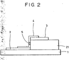
- FIG. 2 is a schematic view of a vertical surface conductive type electron emission device in accordance with the present invention. Parts having the same functions as in Figure 1 are referred to with the same numerals.
- the device has a step section 21 which is composed of an insulating material such as SiO 2 and is formed by a vacuum deposition process, a printing process, or a sputtering process, in addition to electrodes 2 and 3, a conductive thin film 4, and an electron emitting section 5, these parts being composed of the same materials as those in the above-described horizontal surface conductive type electron emission device.
- the thickness of the step section 21 corresponds to the interval L between the electrodes 2 and 3 in the horizontal surface conductive type electron emission device and lies in a range of several hundreds nm (thousands of Angstroms) to several tens of micrometers, and preferably several tens nm (hundreds of Angstroms) to several micrometers in consideration of the method for making the step section 21 and the voltage applied between the electrodes 2 and 3.
- the conductive thin film 4 is deposited on the electrodes 2 and 3.
- the electron emitting section 5 is formed on the step section 21 in Fig. 2, the shape and position of the step section 21 depend on the forming conditions.
- the surface conductive type electron emission device may be produced by various methods.
- Figs 3A to 3C are schematic views showing one of the methods. Parts having the same functions as in Figure 1 are referred to with the same numerals.
- a substrate 1 is thoroughly cleaned with a detergent, purified water or an organic solvent.
- An electrode material is deposited thereon by a vacuum deposition process or a sputtering process, and then patterned to form external electrode 6 by a photolithographic process.
- an organometallic solution is applied onto the substrate 1 provided with the electrodes 2 and 3 to form an organometallic thin film.
- the organometallic solution contains an organometallic compound primarily composed of a metal used for the formation of the conductive thin film 4.
- the organometallic thin film is burned and then patterned by a lift-off or etching process to form a conductive thin film 4.
- the conductive thin film 4 may also be formed by a vacuum deposition process, a sputtering process, a chemical vapor deposition process, a dispersion coating process, a dipping process or a spinning process.
- the substrate is subjected to a forming step by energizing treatment.
- a current is conducted between the conductive thin film 4 through an electrical power source (not shown in the drawing) to form an electron emitting section 5 having a modified structure in the conductive thin film 4. That is, the conductive thin film 4 has a locally destructed, deformed or modified section as a result of the energizing forming treatment.
- This section functions as an electron emitting section 5.
- Figs. 4A and 4B are graphs of waveforms of pulse voltages applied in the energizing forming treatment.
- pulse voltages are preferable.
- pulses having a constant voltage are continuously applied
- Fig. 4B pulses having gradually increasing voltages are continuously applied.
- T1 represents the pulse width
- T2 represent the pulse interval.
- the pulse width T1 lies in a range of 1 microsecond to 10 milliseconds
- the pulse interval T2 lies in a range of 10 microseconds to 100 milliseconds.
- the height of the triangular waves or the peak voltage in the energizing forming treatment is determined depending on type of the surface conductive type electron emission device.
- the pulses are generally applied for several seconds to several tens of minutes under such conditions. Any other pulse waves, for example, rectangular waves, other than triangular waves, also may be used.
- the height of the triangular waves is increased by, for example, 0.1 V for each pulse.
- the energizing forming treatment is performed before the conductive thin film 4 has a predetermined resistance.
- the resistance is measured as follows. A low voltage not causing local destruction or deformation is applied to the conductive thin film 4 during a pause time between the pulses, that is, the pulse interval T2 and the conducted current is measured. For example, a voltage of approximately 0.1 volts is applied to detect the current in the conductive thin film 4. When the resistance reaches 1 M ⁇ or more, the energizing forming treatment is completed.
- the device after the forming treatment is preferably subjected to an activation step.
- the device current If and the emission current Ie significantly change during the activation step.
- pulses are repeatedly applied in an organic gas atmosphere as in the energizing forming treatment.
- the organic gas atmosphere is formed by introducing an organic gas into the vacuum which is achieved using an ion pump.
- suitable organic gas materials include aliphatic hydrocarbons, such as alkanes, alkenes, and alkynes; alcohols; aldehydes; ketones; amines; and organic acids, such as phenol, carboxylic acids, and sulfonic acids.
- aliphatic hydrocarbons such as alkanes, alkenes, and alkynes
- alcohols such as alcohols; aldehydes; ketones; amines
- organic acids such as phenol, carboxylic acids, and sulfonic acids.
- saturated hydrocarbons represented by C n H 2n+2 e.g., methane, ethane, and propane
- unsaturated hydrocarbons represented by C n H 2n , i.e..
- ethylene and propylene ethylene and propylene; and other compounds, i.e., benzene, toluene, methanol, ethanol, formaldehyde, acetaldehyde, acetone, methyl ethyl ketone, methylamine, ethylamine, phenol, formic acid, acetic acid, and propionic acid.
- benzene, toluene methanol, ethanol, formaldehyde, acetaldehyde, acetone, methyl ethyl ketone, methylamine, ethylamine, phenol, formic acid, acetic acid, and propionic acid.
- Carbon and/or a carbonaceous material derived from the atmospheric organic material are deposited on the device during the activation step, and cause significant changes in the device current If and the emission current Ie.
- the activation step is completed when the device current If and the emission current Ie reach predetermined values.
- the pulse width, the pulse interval, and the pulse height are appropriately determined.
- carbon and/or a carbonaceous material includes, for example graphites, such as highly orientated pyrolytic graphite (HOPG) and pyrolytic graphite (PG) or graphitizing carbon (GC); and amorphous carbon.
- the HOPG has a crystal structure composed of substantially complete graphite
- the PG has a slightly disordered crystal structure having a crystal grain size of approximately 20 nm (200 Angstroms)
- the GC has a considerably disordered crystal structure having a crystal grain size of approximately 2mm (20 Angstroms).
- the amorphous carbon includes mixtures of amorphous carbon and microcrystal graphite.
- the thickness of the carbon and/or the carbonaceous material is preferably 50 nm (500 Angstroms) or less, and more preferably 30 nm (300 Angstroms) or less.
- the electron emission device is preferably subjected to a stabilizing step.
- the organic material in the vacuum chamber is evacuated.
- An oil-free evacuation unit is preferably used for evacuating the vacuum chamber, since oil affects characteristics of the device. Examples of such evacuation units include sorption pumps and ion pumps.
- the partial pressure of the organic component in the vacuum chamber be 1.7 x 10 -6 Pa (1.3 x 10 -8 Torr) or less, and more preferably 1 x 10 -8 Pa (1 x 10 -10 Torr) or less, so that the carbon and/or carbonaceous material do not further deposit in this step.
- the vacuum chamber be heated during the evacuation step so that organic molecules adsorbed in the inner wall of the vacuum chamber and in the electron emission device are easily removed and evacuated. Heating is preferably performed at a temperature of 80 to 200°C for 5 hours or more. The heating conditions, however, may be changed without restriction depending on the size and shape of the vacuum chamber and the configuration of the electron emission device.
- the pressure in the vacuum chamber must be decreased as much as possible, and is preferably 1-4 x 10 -5 Pa (1-3 x 10 -7 Torr) or less, and more preferably 1 x 10 -6 Pa (1 x 10 -8 Torr) or less.
- the atmosphere in the stabilizing step be maintained in a driving mode of the electron emission device. Sufficiently stable characteristics, however, can be achieved as long as the organic components are sufficiently removed even when the degree of the vacuum is slightly decreased. As a result, the device current If and the emission current Ie can be stabilized.
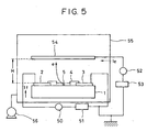
- Fig. 5 is a schematic view of a vacuum unit that also functions as a measuring unit. Parts having the same functions as in Fig. 1 are referred to with the same numerals.
- the vacuum unit has a vacuum chamber 55 and a vacuum pump 56. An electron emission device is placed into the vacuum chamber 55.
- the vacuum unit further has an electrical power source for applying a device voltage Vf to the electron emission device, and an ammeter 50 for detecting a device current If flowing in a conductive thin film 4 between electrodes 2 and 3, and an anode 54 for collecting an emission current Ie from the electron emitting section 5.
- a voltage is applied to the anode 54 through a high-voltage electrical power source 53.
- An ammeter 52 detects the emission current Ie from the electron,emitting section 5. Measurement is performed, for example, at a voltage of the anode of 1 kV to 10 kV, and a distance H between the anode and the electron emission device of 2 to 8 mm.
- the vacuum chamber 55 is provided with a vacuum. indicator (not show in the drawing) and required instruments for the measurement.
- the vacuum pump 55 has a gas inlet section (not shown in the drawing) to control the atmosphere in the vacuum chamber.
- the vacuum unit can be heated to 200°C by a heater (not shown in the drawing).
- the vacuum unit- is capable of performing the steps from the energizing forming treatment.
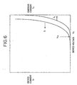
- Fig. 6 is a schematic graph showing the relationship between the emission current Ie or device current If and the device voltage Vf that are measured by the vacuum unit. Since the discharging voltage Ie is significantly smaller than the device voltage If, these voltages are expressed by arbitrary units in Fig. 6. Linear scales express the vertical line and the horizontal axis. As shown in Fig. 6, the surface conductive type electron emission device has the following three characteristics regarding the emission current Ie.
- electron emitting characteristics can be readily controlled in response to the input signal. Such characteristics permit the application of the device in various fields, for example, an electron source and an image forming apparatus including an array of a plurality of electron emission devices.
- Fig. 6 shows a monotone increase in the device current If with respect to the device voltage Vr (hereinafter referred to as an MI characteristic).
- Some devices have a voltage-controlled negative resistance characteristic (hereinafter referred to as a VCNR characteristic), although this is not shown in the drawings.
- the characteristics of the device can be determined by controlling the above-mentioned steps.
- an electron source and an image forming apparatus can be produced by arranging a plurality of surface conductive type electron emission devices.
- the electron emission devices can have various types of arrangements. For example, in a ladder arrangement, many lines of electron emission devices are arranged in the line direction, and control electrodes or grids for controlling electrons from these electron emission devices are disposed on the electron emission devices in a direction perpendicular to the line (or the row direction). In a simple matrix arrangement, electron emission devices are arranged in a matrix in the X and Y directions, one of the electrodes of each electron emission device is connected to a common lead in the X direction, and the other electrode of each electron emission device is connected to a common lead in the Y direction.
- the surface conductive type electron emission device has the above-mentioned three characteristics. That is, electrons discharged from the surface conductive type electron emission device can be controlled by the height and width of the pulse voltage for a voltage higher than the threshold voltage, whereas electrons are not substantially discharged at a voltage lower than the threshold voltage.
- a pulse voltage applied to each device can control electrons discharged from the device.
- X-axis lead lines 72 including DX1, DX2, ⁇ , DXm are composed of a conductive material such as a metal and are formed on an electron source substrate 71 by a vacuum deposition, printing, or sputtering process. The material, thickness, and width of the lead lines can be appropriately determined depending on the purpose.
- Y-axis lead lines 73 including DY1, DY2, ⁇ , DYn are also formed as in the X-axis lead lines 72.
- the X-axis lead lines 72 are electrically isolated from the Y-axis lead lines 73 by an insulating interlayer (not shown in the drawing) provided therebetween.
- the insulating interlayer is composed of, for example, SiO 2 , and formed by a vacuum deposition, printing, or sputtering process on a part or the entirety of the electron source substrate 71.
- the material and process for and the shape and thickness of the insulating interlayer are determined such that the insulating interlayer has durability to a potential difference between the X-axis lead lines 72 and the Y-axis lead lines 73.
- One end of each X-axis lead line 72 and one end of each Y-axis lead line 73 are extracted as external terminals.
- Each of surface conductive type electron emission devices 74 in a matrix (mxn) are connected to the corresponding X-axis lead line 72 and the corresponding Y-axis lead line 73 through a pair of electrodes (not shown in the drawing) provided on the two ends of the surface conductive type electron emission device and a connecting line 75 composed of a conductive metal or the like.
- the surface conductive type electron emission device 74 may be of a horizontal type or a vertical type.
- These lines 72, 73, and 74 and the electrodes may be composed of partially or substantially the same conductive material, or of different conductive materials.
- the X-axis lead lines 72 are connected to a scanning signal application means (not shown in the drawing).
- the scanning signal-application means apply scanning signals for selecting lines of the surface conductive type electron emission devices 74 arranged in the X direction.
- the Y-axis lead lines 73 are connected to a modulation signal application means (not shown in the drawing).
- the modulation signal application means apply modulation signals to the rows of the surface conductive type electron emission devices 74 arranged in the Y direction in response to the input signals.
- a driving voltage applied to each electron emission device corresponds to a differential potential between the scanning signal and the modulation signal applied to the device.
- a simple matrix wiring system can independently drive individual electron emission devices.
- An image forming apparatus using an electron source having a simple matrix arrangement will be described with reference to Figs. 8A, 8B, 9A, 9B, and 10.
- Fig. 8A is a schematic isometric view of a display panel of an image forming apparatus
- Fig. 8B is a cross-sectional view taken along line IX-IX of Fig. 8A.
- numeral 81 represents an electron source substrate as a rear plate provided with a matrix of surface conductive type electron emission devices 74 as shown in Fig. 1
- numerals 72 and 73 represent an X-axis lead line and a Y-axis lead line, respectively, connected to a pair of electrodes in each electron emission device.
- Numeral 86 represents a face plate in which a fluorescent film 84 and a metal back layer 85 are formed on the inner face of a glass substrate 83.
- Numeral 82 represents a frame which is connected to the rear plate 81 and the face plate 86.
- Numeral 89 represents a spacer provided in the display region for reinforcing the strength of the electron source substrate 81. The number and shape of the spacer 89 may be appropriately determined.
- the rear plate 81, the face plate 86, the frame 82, the spacer 89, and other units such as an exhaust pipe are connected with frit glass 80 and 90.
- the rear plate 81 functions as the electron source substrate, an electron source substrate may be provided in addition to the rear plate 81.
- the spacer 89 in the display region may be omitted, if the package has sufficient strength.
- the frit compound is composed of frit glass and a vehicle.
- the frit glass is powdered and is composed of a main component, such as PbO, PbO-B 2 O 3 , or PbO-ZnO-B 2 O 3 , and a filler, such as SnO 2 .
- the frit glass may be a crystalline frit glass or a composite mixture of a crystalline frit glass and an amorphous frit glass.
- the vehicle is composed of at least one component.
- Components which can disperse frit glass and can maintain the shape of the frit glass until the softening point are called binders (organic binders).
- binders include nitrocellulose, ethyl cellulose, and polyisobutyl methacrylate.
- the vehicle may contain a solvent for dispersing the frit glass and dissolving the binder. Examples of such solvents include amyl acetate, terpineol, and other volatile alcohol and ether solvents.
- the frit compound may be applied with a dispenser or by a spraying or printing process.
- the second step components other than the frit glass are removed from the frit compound applied.
- This step is called a calcination step.
- the calcination step is performed at a temperature which is lower than the softening point of the frit glass and higher than the pyrolytic temperature of the vehicle or binder.
- a drying step may be incorporated prior to the calcination step for removing selectively or partially the solvent.
- the third step is a sealing step in which the relevant units are connected to each other with the frit glass.
- the sealing temperature is determined so that the frit glass has sufficient flowability required for the connection.
- the relevant units are positioned and then connected in the sealing step.
- the calcination step and the sealing step may be performed simultaneously.
- the second or calcination step is performed so that the conductive thin film of the electron source substrate is not exposed to evolved gas.
- the frit Compound will be applied, followed by calcinations, to the units connected to the electron source substrate, such as the face plate, the frame, and the spacer, in place of the electron source substrate, in some cases.
- the frit compound When the frit compound is applied onto the electron source substrate in the first step, the conductive thin film is produced after the second step.
- Figs. 9A and 9B are schematic views of fluorescent films.
- a monochrome fluorescent film may comprise only a fluorescent substance 92.
- a coloured fluorescent film may comprise conductive black stripes 91 (in Fig. 9A) or a conductive black matrix 91 (in Fig. 9B) and fluorescent substances 92 depending on the arrangement of the fluorescent substances.
- the black stripe or matrix prevents mixing between adjacent fluorescent substances 92 corresponding to three primary colours and suppression of the contrast due to reflection of external light by the fluorescent film.
- the material for the black stripe or matrix contains graphite as a main component or a component having low light transmittance and reflection.
- the monochrome or colour fluorescent substance may be applied onto a glass substrate 83 to form a fluorescent film 84 by a precipitation or printing process.
- a metal back layer 85 is generally provided on the inner face of the fluorescent film 84.
- the metal back layer 85 as a mirror reflects light emitted from the fluorescent substance towards the face plate 86 and thus improves luminance.
- the metal back layer 85 functions as an electrode for applying an electron beam acceleration voltage and protects the fluorescent substance from damage due to collision of negative ions occurring in the package.
- the metal back layer 85 is generally formed by depositing aluminium by a vacuum deposition process onto the inner surface of the fluorescent film 84 after smoothing treatment (generally called "filming") of the inner surface.
- the face plate 86 may be provided with a transparent electrode (not shown in the drawing) at the outer face of the fluorescent film 84 in order to enhance conductivity of the fluorescent film 84.
- the image forming apparatus shown in Figs. 8A and 8B is produced as follows.
- the package comprising the face plate 86, the rear plate 81, and the frame 82 is heated and evacuated by an oil-free evacuation system, such as an ion pump or a sorption pump, through an evacuation pipe (not shown in the drawings) attached to the package to an atmosphere with a vacuum pressure of 10 -5 Pa (10 -7 Torr) substantially not containing organic substances.
- the package is then sealed, and is subjected to getter treatment, if necessary.
- a getter (not shown in the drawings) provided at a given position in the package is heated immediately before or after the sealing of the package to deposit a film by evaporation.
- the getter is generally composed of barium, and the film has adsorption effects so that the package is maintained at a vacuum pressure in a range of 1 x 10 -3 to 1 x 10 -5 Pa (1x10 -5 to 1x10 -7 Torr). Steps subsequent to the forming treatment of the surface conductive type electron emission devices can be appropriately provided.
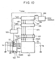
- Fig. 10 is a block diagram of a driving circuit for a television display on the basis of NTSC signals having a display panel including an electron source having a simple matrix arrangement.
- the circuit diagram comprises an image display panel 101. a scanning circuit 102, a control circuit 103, a shift register 1014, a line memory 105, a synchronous separation circuit 106, a modulation signal generator 107, and DC voltage sources Vx and Va.
- the display panel 101 is connected to an external electrical circuit through terminals Dox1 to Doxm and Doy1 to Doyn and a high voltage terminal Hv.
- Scanning signals are applied to the terminals Dox1 to Doxm for driving the electron source provided in the display panel, that is, for driving each line (including N devices) sequentially of a matrix (MxN) of surface conductive type electron emission devices.
- Modulation signals are applied to the terminals Doy1 to Doyn for controlling the intensity of the electron beam output from each electron emission device.
- a DC voltage of, for example, 10 kV is applied to the high-voltage terminal Hv through the DC voltage source Va.
- the DC voltage corresponds to an acceleration voltage that accelerates the electron beams emitted from the surface conductive type electron emission devices to a level capable of exciting the fluorescent substance.
- the scanning circuit 102 has M switching elements S1 to Sm therein, as shown schematically in the drawing. Each switching element selects either an output voltage from the DC voltage source Vx or a ground level (0 volts), and is connected to each of the terminals Dx1 to Dxm in the display panel 201.
- the switching elements S1 to Sm operates based on the control signals Tscan output from the control circuit 103.
- Each switching element comprises, for example, an FET.
- the DC voltage source Vx outputs a constant voltage so that the driving voltage applied to the unscanned devices, on the basis of the characteristics of the surface conductive type electron emission device, is lower than the threshold voltage of electron emission.
- the control circuit 103 controls matching of individual units so that a desired display is achieved based on image signals from the exterior.
- the control circuit 103 generates control signals Tscan, Tsft, and Tmry in response to synchronous signals Tsync sent from the synchronous separation circuit 106.
- the synchronous separation circuit 106 separates the NTSC television signals from the exterior into synchronous signal components and luminance signal components, and comprises a typical frequency separation circuit (filter).
- the synchronous signal components include vertical synchronous signals and horizontal synchronous signals, and are represented by "Tsync".
- the luminance signal components are represented by "DATA signal”.
- the DATA signals enter the shift resister 104.
- the shift resister 104 serial/parallel-converts the DATA signals input in time series corresponding to each line of the image, and operates in response to the control signal Tsft from the control circuit 103.
- the control signal Tsft functions as a shift clock for the shift register 104.
- the serial/parallel-converted data corresponding to one line of the image is output as a N parallel signals Idl to Idn from the shift register 204 to drive N electron emission devices.
- the line memory 105 temporally stores N data Ida to Idn corresponding to one line of the image under the control of the control signal Tmry sent from the control circuit 103.
- the stored data is output as I'dl to K'dn to the modulation signal-generator 107.
- the modulation signal generator 107 produces output signals for driving the surface conductive type electron emission devices in response to the image data I'dl to I'dn, the output signals are applied to the surface conductive type electron emission devices in the display panel 201 through the terminals Doyl to Doyn.
- the electron emission device has the following fundamental characteristics with respect to the emission current Ie. Electron emission occurs when a voltage larger than the threshold voltage Vth is applied to the device, and the emission current, that is, the intensity of the electron beams, varies with at voltages higher than the threshold voltage Vth. Electron emission does not occur at an applied voltage lower than the threshold voltage Vth.
- the intensity of the emitted electron beams is controlled by the pulse height Vm.
- the total amount of the electron beams is also controlled by the pulse width Pw.
- Examples of modulation systems for the electron emission devices in response to the input signals include a voltage modulation system and a pulse width modulation system.
- the voltage modulation system uses a modulation signal generator 107 including a voltage modulation circuit that modulates the height of the voltage pulse having a predetermined length in response to the input data.
- the pulse width modulation system uses a modulation signal generator 107 including a pulse width modulation circuit that modulates the width of the voltage pulse having a predetermined height in response to the input data.
- the shift register 104 and the line memory 105 may be of digital signal types or analog signal types, as long as serial/parallel conversion of the image signals is performed within a predetermined time.
- the output signal DATA from the synchronous separation circuit 106 must be digitized using an A/D converter provided at the output section of the synchronous separation circuit 106.
- the circuit in the modulation signal generator 107 is different between the digital signals and analog signals from the line memory 105. For example, in a voltage modulation system by digital signals, the modulation signal generator 107 has a D/A conversion circuit and an amplification circuit, if necessary.
- the modulation signal generator 107 has a high-speed oscillator, a counter for counting the wave number output from the oscillator, and a comparator for comparing the output value from the counter with the output value from the memory.
- the modulation signal generator 107 may have an amplifier for voltage-amplifying the pulse width modulated signals from the comparator up to a driving voltage of the surface conductive type electron emission device.
- the modulation signal generator 107 has an operational amplifier, and a level shift circuit, if necessary.
- the modulation signal generator 107 has a voltage-controlled oscillator (VCO), and an amplifier, if necessary, for voltage-amplifying the pulse width modulated signals up to a driving voltage of the surface conductive type electron emission device.
- VCO voltage-controlled oscillator
- each electron emission device emits electron beams in response to the voltage applied to the device through the external terminals Dox1 to Doxm and Doy1 to Doyn.
- the electron beams are accelerated by a high voltage applied to the metal back layer 85 or a transparent electrode (not shown in the drawing) through the high-voltage terminal Hv.
- the accelerated electron beams collide with the fluorescent film 84 to form a fluorescent image.
- the input signal may be of a PAL system, a SECAM system, or a high-definition TV system, such as a MUSE system, having a larger number of scanning lines.
- Fig. 11 is a schematic view of a ladder type electron source.
- the electron source includes an electron source substrate 110, and electron emission devices 111 arranged on the electron source substrate 110.
- common lead lines Dx1 to Dx10 connected to the electron emission devices 110.
- the electron emission devices 110 are arranged in series in the horizontal (X-axis) direction to form a plurality of device lines (five in the drawing).
- the electron source comprises a plurality of horizontal device lines. Each device line independently drives by a driving voltage applied to the two common lead lines connected to the device line.
- a voltage higher than the threshold voltage for electron emission is applied to lines that permit emission of electron beams, whereas a voltage lower than the threshold voltage is applied to the other lines that do not permit emission of electron beams.
- lead lines Dx2 to Dx9 disposed between the device lines for example, lead lines Dx2 and Dx3 may be replaced with a common lead line.
- Fig. 12 is a schematic view of a panel of an image forming apparatus provided with the ladder type electron source, wherein numeral 120 represents grid electrodes, and numeral 121 represents openings which allow transit of electrons. Parts having the same functions as in Figure 11 are referred to with the same numerals, and a detailed description thereof with reference to drawings has been omitted.
- the image forming apparatus shown in Figs. 12 is fundamentally different from the simple matrix image forming apparatus shown in Fig. 8 in that the former has the grid electrodes 120 between the electron source substrate 110 and the face plate 86.
- the grid electrodes 120 modulates the electron beams emitted from the surface conductive type electron emission devices.
- Each grid electrode 120 has circular openings 121.
- the number of the openings 121 is equal to the number of devices. Electron beams pass through the openings 121 towards stripe electrodes provided perpendicular to the ladder type device lines.
- the shape and position of the grids are not limited to those shown in Fig. 12.
- the grids may comprise a mesh having many openings or passages.
- the grids may be arranged at the peripheries of, or in the vicinity of, the surface conductive type electron emission devices.
- the outside terminals are connected to a control circuit (not shown in the drawing).
- each device line is driven or scanned in series while a series of modulation signals corresponding to one line of image are synchronously applied to the corresponding grid electrode rows.
- the fluorescent substance is irradiated with the emitted electron beams to cause fluorescence with various luminances corresponding to one line of image.
- the image forming apparatus can be applied to display devices for television broadcasting, television conferencing, and computer systems, and to optical printers provided with photosensitive drums.
- Example 1 as a background example, will be described first with reference to Figs. 1A, 1B, 3A to 3C, 8A, 8B and 13A to 13C.
- frit compound is not applied onto the rear plate (electron source substrate).
- an electron source substrate 81 provided with a matrix of surface conductive type electron emission devices 74 was produced in the following steps 1 to 5.
- Step 1) With reference to Figs. 1A and 1B, a blue plate glass substrate 1 was cleaned.
- Step 2 A plurality of electrode groups each including a pair of electrodes 2 and 3 were formed on the glass substrate 1 by a thick-film screen printing process to form a matrix of the electrode groups.
- the used thick-film paste is an MOD paste (DU-2120 made by Noritake Co., Ltd.) and contains gold as a metal component.
- the substrate was dried at 100°C for 20 minutes, and then fired at 580° C for approximately 8 minutes.
- the thickness of the electrodes after firing was 0.3 ⁇ m.
- the distance between the electrodes 2 and 3 was 50 ⁇ m.
- Step 3 With reference now to Fig. 8A, Y-axis lead lines 73 were formed on the substrate 81 (corresponding to the substrate 1 in Figs. 1A and 1B) by a thick-film screen printing process using a paste NP-4028A made by Noritake Co., Ltd., containing silver as a metal component.
- the substrate 81 was fired under the same conditions as in the step 2.
- Each Y-axis lead line 73 was connected to the electrodes 2 (Figs. 1A and 1B) in the corresponding row.
- Step 4) An insulating interlayer (not shown in the drawing) was formed between the Y-axis lead liens 73 and X-axis lead lines 72 that will be formed in the subsequent step 5 by a thick-film screen printing process using a paste containing a mixture of PbO as a primary component and a glass binder under the same firing conditions as in the step 2.
- the insulating interlayer secures electrical insulation between the lead line 73 and the lead line 72.
- Step 5 The X-axis lead lines 72 were formed by the same procedure as in the Y-axis lead lines 73. Each X-axis lead line 72 was connected to the electrodes 3 (Figs. 1A and 1B) in the corresponding line.
- a conductive thin film 4 was formed over each pair of electrodes 2 and 3 in the following step 6.
- Step 6 An organic palladium compound (CCP4230 made by Okuno Chemical Industries Co., Ltd.) was sprayed onto the substrate through a mask having 300- ⁇ m square patterns. The substrate was fired at 350°C for 1 hour to form a PdO conductive thin film 4 over the electrodes 2 and 3.
- the conductive thin film 4 had a thickness of 15 nm, was composed of fine particles having a particle size of approximately 7 nm, and had a sheet resistance of 5 ⁇ 10 4 ⁇ /sheet.
- An electron emitting section was formed in the conductive thin film 4 in the following steps 7 to 9.
- Step 7) With reference to Fig. 8A, the substrate was placed into a glass container, and the X-axis lead lines Dx1 to Dxm and the Y-axis lead lines Dyl to Dym were connected to external terminals (not shown in the drawing).
- the glass container was thoroughly evacuated using a vacuum pump to a high degree of vacuum.
- a predetermined sequence of triangular pulse voltages was applied to each pair of electrodes through the external terminals so that the conductive thin film 4 disposed over the electrodes was subjected to forming treatment.
- the pulse voltages were gradually increased as shown in Fig. 48.
- An electron emitting section 5 was thereby formed in the centre of the conductive thin film 4.
- Step 8) The substrate provided with the electron emitting sections 5 was subjected to activation treatment. Acetone was introduced into the vacuum glass container until the pressure became approximately 1x10 -3 Pa (1x10 -5 Torr) while each device was driven for one hour. Carbon was deposited on each device and thus the device current If and the emission current Ie increased.
- Step 9) The glass chamber was evacuated to a vacuum pressure of approximately 1x10 -4 Pa (1x10 -6 Torr) and then heated to 150°C for one hour to stabilize the electron emitting sections 5 without further deposition of carbon.
- the electron source substrate 81 as shown in Fig. 8A was thereby formed.
- the glass container was released to atmospheric pressure to remove the substrate.
- a face plate 86 in Fig. 8A was produced as follows. Black stripes composed of graphite as a main component were formed on a glass substrate 83, colour fluorescent substances were applied onto spaces between the stripes by a slurry coating process to form a fluorescent film. The inner surface of the fluorescent film was subjected to smoothing (generally called filming), and then aluminum was deposited on the smoothed surface by a vacuum deposition process to form a metal back layer 86.
- a transparent electrode (not shown in the drawing) may be provided on the outer surface to enhance the conductivity of the fluorescent film; however, it was not formed in this example since the metal back layer 85 had sufficiently high conductivity.
- an image forming apparatus was produced using the electron source substrate 81 and the face plate 86 provided with the fluorescent film 84 and the metal back layer 85 as follows.
- the electron source substrate 81 was used as a rear plate.
- the height of the frame 82 was 4 mm.
- a frit compound 131 was applied at positions for placing a spacer 89 and a frame 82 on the face plate 86.
- Crystalline frit glass powder LS-7105 made by Nippon Sheet Glass Co., Ltd. was used as the frit compound.
- Polyisobutyl methacrylate as a binder and terpineol as a solvent were mixed with the frit glass powder so as to impart a desired viscosity to.the glass powder paste.
- the frit compound 131 was applied using a discharging unit provided with a dispenser so that the nearest distance between the frame 82 and the electron emission devices 74 on the electron source substrate 81 was 30 nm and the distance between the spacer 89 and the electron emission device 74 was 1 mm.
- the face plate 86 with the spacer 89 and the frame 82, and the rear plate 81 were exactly aligned so that each color fluorescent substance and the corresponding electron emission device lie at the same position.
- the frit glass was fired at a temperature higher than the calcination temperature, that is, 450°C for 20 minutes in the atmosphere to securely seal the connections, as shown in Fig. 13C.
- the resulting package comprising the face plate 86, the flame 82, and the rear plate 81 was evacuated by a vacuum chamber through an exhaust pipe (not shown in the drawing).
- the exhaust pipe was sealed and then the package was subjected to getter treatment to maintain a high vacuum.
- scanning signals and modulation signals from a signal generator were applied to the resulting image forming apparatus through external terminals Dxl to Dxm, Dyl to Dym, respectively, and the emitted electron beams were accelerated by a high voltage of 4 kV applied to the metal back layer through the high-voltage terminal Hv.
- the accelerated electron beams collided with the fluorescent film 84 to form a fluorescent image.
- This image forming apparatus has a small depth because the thickness of the display panel provided with an electron beam source of surface conductive type electron emission devices can be readily achieved.
- the display panel with a large area and high luminance has a large view angle. Accordingly, the image forming apparatus can display images with the feeling of being at a live performance and high visibility.
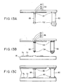
- an image forming apparatus as shown in Figs. 15A to 15C was formed as follows, wherein the production of the rear plate and face plate, the composition and heating temperature of the frit glass were the same as in Example 1.
- the frit compound. 131 and 132 were applied onto both the rear plate 81 and the face plate 86, as shown in Fig. 15A, and then subjected to calcination, as shown in Fig. 15B.
- the frame 82 and the spacer 89 were placed at the positions 131 and 132 of the frit compound (Fig. 15B), and then the face plate 81, the spacer 89, the frame 82, and the rear plate 81 were fixed as in Example 1 (Fig. 15C).
- Example 1 and Referential Example 1 the vehicle in the frit compound is decomposed to evolve gas.
- the temperature of gas evolution and the type and volume of the evolved gas depend on the composition and amount of the vehicle and the atmosphere.
- gas due to evaporation and/or pyrolysis of terpineol as the solvent was evolved at a temperature up to 200°C
- gas due to pyrolysis of polyisobutyl methacrylate as the binder was evolved at 200 to 380°C.
- the main components of the gas were reductive gas, such as H 2 , and COH 4 , and other gas, such as H 2 O and CO 2 .
- Fig. 14 is a flow chart of the production steps in Example 1
- Fig. 16 is a flow chart of the production steps in Referential Example 1.
- Example 1 the frit compound is applied to the face plate, the frame and the spacer, followed by calcination: hence the rear plate provided with the electron source is not subjected to application and calcination of the frit compound.
- the elements of the electron emission device do not come into contact with the reductive gas formed during the calcination.
- Referential Example 1 the frit compound is applied to the rear and face plates, hence the elements of the electron emission device inevitably comes into contact with the reductive gas formed during the calcination at a high temperature.
- the electron emission devices in the image forming apparatus produced in Example 1 have superior characteristics to the devices in Referential Example 1, as follows.
- the device current If per device at a driving voltage of 18 V is approximately 1 mA for Example 1 or 0.15 mA for Referential Example 1, the emission current Ie per device is approximately 0.8 ⁇ A for Example 1 or 0.005 ⁇ A for Referential Example 1.
- Example 2 another background example, a conductive thin film 4 was first formed, a sealing step was performed, and then an electron emitting section 5 was formed in the conductive thin film 4.
- the frit compound was applied onto the rear plate as in Example 1.
- the frit compound used was a mixture of crystalline glass powder, amorphous glass powder, and nitrocellulose as a binder.
- Fig. 17 is a flow chart of production steps in Example 2.
- An electron source substrate provided with conductive thin films 4 in a matrix, each being formed over a pair of electrodes was produced by steps 1 to 6 in Example 1.
- No electron emitting section 5 was, however, formed in the conductive thin film 4 in this stage.
- An image forming apparatus was assembled using the electron source substrate without an electron emitting section 5 as a rear plate 81 and the face plate 86.
- the frit compound 131 was applied at positions for placing the spacer 89 and the frame 82 on the face plate 86.
- the frit compound was composite frit glass powder LS-3081 made by Nippon Plate Glass Co., Ltd. The powder was mixed with a nitrocellulose binder and a terpineol solvent to achieve a desired viscosity of the frit compound.
- the frit compound was applied using a discharging unit with a dispenser.
- the spacer 89 and the frame 82 were aligned and then connected to the face plate 86.
- the frit compound was applied onto the other ends of the spacer 89 and the frame 82, and then these were subjected to calcination at a temperature of 380°C for 10 minutes in the atmosphere.
- the face plate 86 and the rear plate 81 were exactly aligned, and then the frit compound was fired at a temperature higher than the calcination temperature, that is, 410°C for 10 minutes in the atmosphere to seal the connection of the frit compound.
- An electron emitting section 5 was formed in the conductive thin film 4 as follows. A package comprising the face plate 86, the frame 82, and the rear plate 81 was thoroughly evacuated by a vacuum pump through an exhaust pipe (not shown in the drawing), and then a voltage was applied to a pair of electrodes of each device through external terminals Dxol to Doxm and Dyol to Dyon so that the conductive thin film 4 disposed over the electrodes was subjected to the forming treatment as in Example 1. The electron emitting section 5 was thereby formed in the conductive thin film 4.
- Acetone was Introduced into the package so that the pressure became approximately 1 x 10 -3 Pa (1x10 -5 Torr) and then each device was driven for one hour to deposit carbon on the device.
- the activation treatment resulted in increases in the device current If and the emission current.
- the package was evacuated to a high degree of vacuum of approximately 1 x 10 -4 Pa (1x10 -6 Torr) and heated to 150°C for one hour to stabilize the device.
- the electron emission device 74 was thereby produced.
- the exhaust pipe (not shown in the drawing) was sealed and then the package was subjected to getter treatment to maintain a high vacuum.
- Example 2 the frit compound is applied to the face plate 86, the frame 82 and the spacer 89, followed by calcination; hence the rear plate 81 provided with the electron source is not subjected to application and calcination of the frit compound.
- the elements of the electron emission device do not come into contact with the reductive gas formed during the calcination.
- the electron emission devices in the image forming apparatus produced in Example 1 have superior characteristics, such as a high emission current Ie, regardless of the type and the frit compound, and the composition of the vehicle. The device, therefore, can display significantly uniform, stable images.
- Fig. 18 is a flow chart of production steps in Referential Example 2, in which the frit compound is also applied to the rear plate and subjected to calcination as in Referential Example 1, after the formation of the conductive thin film 4 in the electron emission device as in Example 2.
- the composition of the frit compound and the heating temperature are the same as those in Example 2.
- the frit compound is applied to the rear and face plates, hence the elements of the electron emission device inevitably comes into contact with the reductive gas formed during the calcination at a high temperature.
- the image forming apparatus in Example 2 has a higher emission current Ie than that in Referential Example 2.
- the frit compound may be applied to these two ends of the frame and the spacer, without application onto the face plate.
- Example 3 is a Specific Example of a method of manufacturing an image forming apparatus that is in accordance with the present invention.
- Fig. 19 is a flow chart of production steps in Example 3.
- the production steps were modified from those in Examples 1 and 2. That is, the process in Example 3 includes a step of applying the frit compound on the rear plate.
- the composition of the frit compound, the conditions for application, calcination, and sealing were the same as those in Example 1.
- An electron source substrate provided with a matrix of paired electrodes connected to X- and Y-axis lead lines 72 and 73 was produced as in steps 1 to 5, and used as a rear plate 81.
- the frit agent 132 was applied at predetermined positions to provide the spacer 89 and the frame 82 on the rear plate 81. Also, the frit agent 132 was applied at predetermined positions to provide the spacer 89 and the frame 82 on the face plate 86. Both the rear plate 81 and the face plate were subjected to calcination under the conditions as in Example 1.
- a conductive thin film 4 was formed over each pair of electrodes according to step 6 in Example 3.
- the rear plate 81, the face plate 86, the frame 82, and the spacer 89 were aligned and then bonded to each other by sealing.
- An electron emitting section 5 was formed in each conductive thin film 4 as in Example 2, was subjected to activation treatment.
- the package comprising the face plate, the frame, and the rear plate was thoroughly evacuated and sealed to form an image forming apparatus.
- Example 3 the order of the sealing and the formation of the electron emitting section is changeable.
- Example 3 the conductive thin film 4 and the electron emitting section 5 do not come into contact with the reductive gas.
- the image forming apparatus has electron emission devices with superior electron discharging characteristics, such as a large emission current Ie.
- Example 4 is a Specific Example of another method of manufacturing an image forming apparatus that is -in accordance with the present invention.
- Fig. 20 is a flow chart of a production process in Example 4.
- the production steps were modified from those in Examples 1 and 2.
- the process in Example 4 includes a step of applying the frit compound on the rear plate.
- the composition of the frit compound, the conditions for application, calcination, and sealing were the same as those in Example 1.
- palladium acetate was used instead of the organic palladium compound in Example 1.
- An electron source substrate provided with a matrix of electron emission devices was produced by the steps 1 to 6 in Example 1.
- Example 4 The firing of palladium acetate and calcination of the frit compound were simultaneously performed in Example 4. Palladium acetate was applied over each pair of electrodes, and then the frit compound was applied onto predetermined positions of the electron source substrate. The electron source substrate was heated to form a conductive thin film 4 by pyrolysis of palladium acetate and to achieve calcination of the frit compound. The frit compound was also applied to predetermined positions on the face plate and then subjected to calcination. The electron source substrate, the face plate, the frame, and the spacer were exactly aligned and then bonded to each other by sealing. An electron emission section was formed on the conductive thin film 4 and activated as in Example 2. The package comprising the electron source substrate, the face plate and the frame was thoroughly evacuated and then sealed. The electron emitting section may be formed after the bonding of the package members.
- Electron emission devices of the image forming apparatus in Example 4 had superior electron discharging characteristics, such as a large emission current Ie.
Landscapes
- Engineering & Computer Science (AREA)
- Manufacturing & Machinery (AREA)
- Cathode-Ray Tubes And Fluorescent Screens For Display (AREA)
Claims (5)
- Verfahren zur Anfertigung.eines Bilderzeugungsgeräts, das sich aus einer mit einem Bilderzeugungselement (84) versehenen Frontplatte (86) und einer mit Elektronenemissionseinheiten (74) versehenen Rückplatte (81) zusammensetzt und bei dem Frontplatte und Rückplatte die Elektronenemissionseinheiten umschließend abgedichtet (82) sind, wobei das Verfahren Folgendes beinhaltet:einen Aufbringungsschritt, bei dem auf eine vorbestimmte Fläche einer Rückplatte (81) eine Frittenmasse (132) aufgebracht wird;einen Kalzinierungsbehandlungsschritt, der unter Aufbringung von Wärme erfolgt, um die Frittenmasse zu zersetzen, und in dem sich Reduktionsgase entwickeln und ausgestoßen werden; undSchritte, bei denen die Rückplatte (81) an der mit einem Bilderzeugungselement (84) versehenen Frontplatte (86) montiert und abgedichtet wird,dadurch gekennzeichnet, dass
der Kalzinierungsbehandlungsschritt des Aufbringens von Wärme zum Zersetzen der Frittenmasse (132) entweder vor oder gleichzeitig mit einem Schritt erfolgt, bei dem auf der Rückplatte ein leitender Dünnfilm (4) erzeugt wird, wobei der leitende Dünnfilm (4) anschließend einer Erregungsformierbehandlung unterzogen wird, um die Elektronenemissionseinheiten (74) auszubilden; und
die Schritte des Montierens und Abdichtens erfolgen, indem für die Frontplatte (86) eine Frontplatte verwendet wird, die ebenfalls eine vorbestimmte Fläche darauf aufgebrachter Frittenmasse hat, die durch Kalzinierung vorbehandelt worden ist. - Verfahren nach Anspruch 1, bei dem die Erregungsformierbehandlung vor dem Schritt des Abdichtens der Rückplatte an der Frontplatte erfolgt.
- Verfahren nach Anspruch 1, bei dem die Erregungsformierbehandlung nach dem Schritt des Abdichtens der Rückplatte an der Frontplatte erfolgt.
- Verfahren zur Herstellung einer Rückplatte (81) zum Einbau bei der Fertigung eines Bilderzeugungsgeräts, das sich aus einer mit einem Bilderzeugungselement versehenen Frontplatte (86) und der Rückplatte (81) zusammensetzt, die in dem gemäß einem der Ansprüche 1-3 angefertigten Bilderzeugungsgerät mit Elektronenemissionseinheiten (74) versehen ist, und bei dem Frontplatte und Rückplatte die Elektronenemissionseinheiten umschließend abgedichtet (82) sind, wobei das Verfahren Folgendes beinhaltet:einen Aufbringungsschritt, bei dem auf eine vorbestimmte Fläche der Rückplatte (81) eine Frittenmasse aufgebracht wird;einen Kalzinierungsschritt, der unter Aufbringung von Wärme erfolgt, um die Frittenmasse zu zersetzen, und in dem sich Reduktionsgase entwickeln und ausgestoßen werden; undeinem Erzeugungsschritt, bei dem auf der Rückplatte ein leitender Dünnfilm erzeugt wird, der zum Ausbilden der Elektronenemissionseinheiten (74) dient, wobei der Erzeugungsschritt gleichzeitig mit oder nach dem Kalzinierungsschritt erfolgt.
- Verfahren, wie es in Anspruch 4 definiert ist, zur Herstellung einer Rückplatte (81) zum Einbau, wobei der leitende Dünnfilm einer Erregungsformierbehandlung unterzogen wird, um die Elektronenemissionseinheiten (74) auszubilden.
Applications Claiming Priority (2)
| Application Number | Priority Date | Filing Date | Title |
|---|---|---|---|
| JP36081497 | 1997-12-26 | ||
| JP36081497 | 1997-12-26 |
Publications (2)
| Publication Number | Publication Date |
|---|---|
| EP0926696A1 EP0926696A1 (de) | 1999-06-30 |
| EP0926696B1 true EP0926696B1 (de) | 2006-12-13 |
Family
ID=18471040
Family Applications (1)
| Application Number | Title | Priority Date | Filing Date |
|---|---|---|---|
| EP98310745A Expired - Lifetime EP0926696B1 (de) | 1997-12-26 | 1998-12-24 | Verfahren zum herstellen eines Bilderzeugungsgerätes |
Country Status (3)
| Country | Link |
|---|---|
| US (1) | US6309272B1 (de) |
| EP (1) | EP0926696B1 (de) |
| DE (1) | DE69836618T2 (de) |
Families Citing this family (11)
| Publication number | Priority date | Publication date | Assignee | Title |
|---|---|---|---|---|
| DE69919242T2 (de) * | 1998-02-12 | 2005-08-11 | Canon K.K. | Verfahren zur Herstellung eines elektronenemittierenden Elementes, Elektronenquelle und Bilderzeugungsgerätes |
| JP3754883B2 (ja) * | 2000-03-23 | 2006-03-15 | キヤノン株式会社 | 画像表示装置の製造法 |
| TW509960B (en) * | 2000-04-04 | 2002-11-11 | Matsushita Electric Industrial Co Ltd | Highly productive method of producing plasma display panel |
| AU2001276946A1 (en) * | 2000-09-05 | 2002-03-22 | Motorola, Inc. | Method of manufacturing a field emission device |
| JP2002245941A (ja) * | 2001-02-13 | 2002-08-30 | Nec Corp | プラズマディスプレイパネルの製造方法 |
| JP3667301B2 (ja) * | 2001-06-15 | 2005-07-06 | キヤノン株式会社 | 真空容器および該真空容器を用いた画像形成装置の製造方法 |
| JP3984946B2 (ja) * | 2002-12-06 | 2007-10-03 | キヤノン株式会社 | 画像表示装置の製造方法 |
| US20050162713A1 (en) * | 2004-01-27 | 2005-07-28 | Samsung Electronics Co., Ltd. | Image-forming apparatus having a pause function and method thereof |
| JP2005255845A (ja) * | 2004-03-11 | 2005-09-22 | Toshiba Corp | マンガン付活ケイ酸亜鉛蛍光体及びこれを用いた画像表示装置 |
| KR100958480B1 (ko) * | 2005-09-29 | 2010-05-17 | 파나소닉 주식회사 | 유기 el 디스플레이 및 그 제조 방법 |
| US9576868B2 (en) * | 2012-07-30 | 2017-02-21 | General Electric Company | Semiconductor device and method for reduced bias temperature instability (BTI) in silicon carbide devices |
Family Cites Families (10)
| Publication number | Priority date | Publication date | Assignee | Title |
|---|---|---|---|---|
| US4427479A (en) * | 1980-08-29 | 1984-01-24 | David Glaser | Flat-panel display and method of manufacture |
| EP0299461B1 (de) | 1987-07-15 | 1995-05-10 | Canon Kabushiki Kaisha | Elektronenemittierende Vorrichtung |
| JPS6431332A (en) | 1987-07-28 | 1989-02-01 | Canon Kk | Electron beam generating apparatus and its driving method |
| JPH0790449B2 (ja) | 1988-04-07 | 1995-10-04 | 株式会社ダイフク | 加工設備 |
| JP2610160B2 (ja) | 1988-05-10 | 1997-05-14 | キヤノン株式会社 | 画像表示装置 |
| US5505647A (en) * | 1993-02-01 | 1996-04-09 | Canon Kabushiki Kaisha | Method of manufacturing image-forming apparatus |
| JP3222357B2 (ja) | 1994-06-09 | 2001-10-29 | キヤノン株式会社 | 画像形成装置及びその製造方法 |
| US5587622A (en) * | 1994-07-12 | 1996-12-24 | Fallon Luminous Products | Low pressure gas discharge lamps with low profile sealing cover plate |
| JPH08138554A (ja) | 1994-11-09 | 1996-05-31 | Canon Inc | 平板型画像表示装置の製造方法 |
| US5820435A (en) * | 1996-12-12 | 1998-10-13 | Candescent Technologies Corporation | Gap jumping to seal structure including tacking of structure |
-
1998
- 1998-12-17 US US09/213,859 patent/US6309272B1/en not_active Expired - Lifetime
- 1998-12-24 EP EP98310745A patent/EP0926696B1/de not_active Expired - Lifetime
- 1998-12-24 DE DE69836618T patent/DE69836618T2/de not_active Expired - Fee Related
Also Published As
| Publication number | Publication date |
|---|---|
| DE69836618T2 (de) | 2007-09-27 |
| US6309272B1 (en) | 2001-10-30 |
| DE69836618D1 (de) | 2007-01-25 |
| EP0926696A1 (de) | 1999-06-30 |
Similar Documents
| Publication | Publication Date | Title |
|---|---|---|
| EP0836213B1 (de) | Bilderzeugungsgerät | |
| US6309272B1 (en) | Method of making an image forming apparatus | |
| JP3217949B2 (ja) | 電子放出素子、電子源、表示素子及び画像形成装置の製造方法 | |
| JP3423519B2 (ja) | 画像形成装置 | |
| JP3559689B2 (ja) | 電子放出素子、電子源、画像形成装置及びそれらの製造方法 | |
| JP3296549B2 (ja) | インクジェット噴射装置及びそれに用いるインクジェットインク | |
| JPH09245697A (ja) | 画像表示装置および該装置の製造方法 | |
| JP3294487B2 (ja) | 電子放出素子の製造方法、並びにそれを用いた電子源、表示パネルおよび画像形成装置の製造方法 | |
| JP3402891B2 (ja) | 電子源および表示パネル | |
| JP3416376B2 (ja) | 表面伝導型電子放出素子の製造方法並びにそれを用いた電子源基板および画像形成装置の製造方法 | |
| JP3472033B2 (ja) | 電子源基板の製造方法および画像形成装置の製造方法 | |
| JP3524278B2 (ja) | 画像形成装置 | |
| JP3582761B2 (ja) | 電子放出部形成用有機金属化合物、並びに電子放出素子、電子源および画像形成装置の製造方法 | |
| JPH11250804A (ja) | 画像形成装置の製造方法 | |
| JP3428806B2 (ja) | 電子放出素子、電子源基板、および画像形成装置の製造方法 | |
| JPH09106760A (ja) | 電子放出素子、電子源、表示素子及び画像形成装置の製造方法 | |
| JPH11329221A (ja) | ペースト状物質の塗布方法及び前記塗布方法を用いた画像表示装置 | |
| JP3423527B2 (ja) | 電子放出素子、電子源基板、電子源、表示パネル、および画像形成装置の製造方法 | |
| JP3548431B2 (ja) | 電子源、該電子源を用いた画像形成装置 | |
| JP3587335B2 (ja) | 電子放出素子形成用有機金属化合物、並びに電子放出素子および画像形成装置の製造方法 | |
| JP2000082384A (ja) | 電子放出素子、電子源及び画像形成装置並びに電子放出素子の製造方法 | |
| JP3217946B2 (ja) | 電子放出部形成用材料並びに該材料を用いた電子放出素子、電子源、表示素子及び画像形成装置の製造方法 | |
| JPH11191369A (ja) | 電子放出素子および画像形成装置の製造方法 | |
| JPH09330652A (ja) | 電子放出素子の製造方法ならびに電子放出素子および画像形成装置 | |
| JP2000231875A (ja) | 電子源の製造方法及び装置 |
Legal Events
| Date | Code | Title | Description |
|---|---|---|---|
| PUAI | Public reference made under article 153(3) epc to a published international application that has entered the european phase |
Free format text: ORIGINAL CODE: 0009012 |
|
| AK | Designated contracting states |
Kind code of ref document: A1 Designated state(s): DE FR GB |
|
| AX | Request for extension of the european patent |
Free format text: AL;LT;LV;MK;RO;SI |
|
| 17P | Request for examination filed |
Effective date: 19991115 |
|
| AKX | Designation fees paid |
Free format text: DE FR GB |
|
| 17Q | First examination report despatched |
Effective date: 20020820 |
|
| GRAP | Despatch of communication of intention to grant a patent |
Free format text: ORIGINAL CODE: EPIDOSNIGR1 |
|
| GRAS | Grant fee paid |
Free format text: ORIGINAL CODE: EPIDOSNIGR3 |
|
| GRAA | (expected) grant |
Free format text: ORIGINAL CODE: 0009210 |
|
| AK | Designated contracting states |
Kind code of ref document: B1 Designated state(s): DE FR GB |
|
| REG | Reference to a national code |
Ref country code: GB Ref legal event code: FG4D |
|
| REF | Corresponds to: |
Ref document number: 69836618 Country of ref document: DE Date of ref document: 20070125 Kind code of ref document: P |
|
| ET | Fr: translation filed | ||
| PLBE | No opposition filed within time limit |
Free format text: ORIGINAL CODE: 0009261 |
|
| STAA | Information on the status of an ep patent application or granted ep patent |
Free format text: STATUS: NO OPPOSITION FILED WITHIN TIME LIMIT |
|
| 26N | No opposition filed |
Effective date: 20070914 |
|
| PGFP | Annual fee paid to national office [announced via postgrant information from national office to epo] |
Ref country code: DE Payment date: 20081231 Year of fee payment: 11 |
|
| PGFP | Annual fee paid to national office [announced via postgrant information from national office to epo] |
Ref country code: GB Payment date: 20081224 Year of fee payment: 11 |
|
| PGFP | Annual fee paid to national office [announced via postgrant information from national office to epo] |
Ref country code: FR Payment date: 20081222 Year of fee payment: 11 |
|
| GBPC | Gb: european patent ceased through non-payment of renewal fee |
Effective date: 20091224 |
|
| REG | Reference to a national code |
Ref country code: FR Ref legal event code: ST Effective date: 20100831 |
|
| PG25 | Lapsed in a contracting state [announced via postgrant information from national office to epo] |
Ref country code: FR Free format text: LAPSE BECAUSE OF NON-PAYMENT OF DUE FEES Effective date: 20091231 |
|
| PG25 | Lapsed in a contracting state [announced via postgrant information from national office to epo] |
Ref country code: DE Free format text: LAPSE BECAUSE OF NON-PAYMENT OF DUE FEES Effective date: 20100701 |
|
| PG25 | Lapsed in a contracting state [announced via postgrant information from national office to epo] |
Ref country code: GB Free format text: LAPSE BECAUSE OF NON-PAYMENT OF DUE FEES Effective date: 20091224 |