EP0926055A2 - Véhicule de transport pliable - Google Patents
Véhicule de transport pliable Download PDFInfo
- Publication number
- EP0926055A2 EP0926055A2 EP98123888A EP98123888A EP0926055A2 EP 0926055 A2 EP0926055 A2 EP 0926055A2 EP 98123888 A EP98123888 A EP 98123888A EP 98123888 A EP98123888 A EP 98123888A EP 0926055 A2 EP0926055 A2 EP 0926055A2
- Authority
- EP
- European Patent Office
- Prior art keywords
- plate
- steering
- vehicle according
- steering device
- bearing
- Prior art date
- Legal status (The legal status is an assumption and is not a legal conclusion. Google has not performed a legal analysis and makes no representation as to the accuracy of the status listed.)
- Withdrawn
Links
Images


Classifications
-
- B—PERFORMING OPERATIONS; TRANSPORTING
- B62—LAND VEHICLES FOR TRAVELLING OTHERWISE THAN ON RAILS
- B62K—CYCLES; CYCLE FRAMES; CYCLE STEERING DEVICES; RIDER-OPERATED TERMINAL CONTROLS SPECIALLY ADAPTED FOR CYCLES; CYCLE AXLE SUSPENSIONS; CYCLE SIDE-CARS, FORECARS, OR THE LIKE
- B62K3/00—Bicycles
- B62K3/002—Bicycles without a seat, i.e. the rider operating the vehicle in a standing position, e.g. non-motorized scooters; non-motorized scooters with skis or runners
-
- B—PERFORMING OPERATIONS; TRANSPORTING
- B62—LAND VEHICLES FOR TRAVELLING OTHERWISE THAN ON RAILS
- B62K—CYCLES; CYCLE FRAMES; CYCLE STEERING DEVICES; RIDER-OPERATED TERMINAL CONTROLS SPECIALLY ADAPTED FOR CYCLES; CYCLE AXLE SUSPENSIONS; CYCLE SIDE-CARS, FORECARS, OR THE LIKE
- B62K15/00—Collapsible or foldable cycles
- B62K15/006—Collapsible or foldable cycles the frame being foldable
Definitions
- the invention relates to a foldable transport vehicle according to the preamble of claim 1.
- Foldable vehicles of this type are particularly in the inner city area due to the possibility of carrying the vehicle when folded or to be dragged into buildings or public transport or in To accommodate storage space of a motor vehicle, a considerable advantage. Little one and manoeuvrable vehicles of this type can also be used advantageously in large areas Companies or facilities such as airports.
- a steering column is typically used in such foldable transport vehicles guided in a steering head, which also mechanical means for Folding the steering device against a step plate with a usually non-steerable rear wheel.
- Such transport vehicles are, for example known from G 84 01 058.4 U1 or DE 94 03 582 U1.
- One out the arrangement known from WO 95/34461 A1 provides one with struts and stiffeners significantly more complex steering device in which the steerability of the front wheel by storing extensions of the front wheel axle in Guide slots of extensions of the tread plate is realized.
- the object of the present invention is a foldable transport vehicle indicate that with little mechanical effort an uncomplicated enables and safe operation in the driving state and in the merged Condition of a small pack size and easy handling offers.
- the steering plate used according to the invention allows easy attachment both the front wheel and the steering device on appropriate holding means and at the same time offers thanks to the large diameter of the bearing ring a stable mounting of the steering arrangement in all driving situations.
- the low position of the bearing level enables positioning close to the wheel axis a folding device for the steering device, from which a particularly inexpensive Pack size results.
- the steering device is firmly connected to the steering plate, so that there is direct steering.
- Under the tread plate is a front wheel arrangement understood and supporting part of the vehicle connecting rear wheel arrangement, which is not necessarily the shape of a flat or flat one Has plate, but in particular also has stiffeners and also as Lightweight lattice structure or the like. Can be carried out.
- a step plate also serves as a step surface for the transport of loads as a loading area.
- the bearing preferably comprises a ball bearing with between the bearing surfaces running bearing balls, but can also be equipped with bearing rollers or be designed as a plain bearing.
- the bearing surface of the steering plate is doing so under the bearing surface of the tread plate.
- the steering plate can be in one piece be executed, but can also be composed of several components be.
- the tread plate shows a section within the storage area, which is preferably is circular.
- securing means are advantageously provided on the tread plate, which are connected to the steering plate by the cutout of the tread plate and reach over the edge of the cutout of the tread plate.
- Wheel suspensions in rotatable plates are known per se, for example from US 1,853,738, FR 705 063 or DE 889 407, but no folding of the vehicle is provided or is possible.
- the steering engages, for example via a chain drive, on a ring in the storage area.
- the steering plate against displacements parallel to the plane to hold and / or guide the bearing ring.
- a circular cylindrical guide ring be connected to the steering plate and through the cutout of the tread plate protrude through.
- the outer diameter of the guide ring is slightly smaller than the inside diameter of the circular cutout of the tread plate.
- the guide ring and the locking ring together also provide protection against the penetration of dirt into the bearing arrangement.
- the steering plate is advantageously designed as a flat plate, which a Has recess through which the front wheel protrudes.
- the holding devices for the folding steering device advantageously point for the folding movement in the direction of the driving position Stop elements on which the steering device for driving is determined, especially using quick release fasteners.
- the lateral distance of the second holding means for the steering device from the steering axis is preferably greater than the corresponding distance first holding means so that the steering device on the holding means on the Steering plate is stably supported and the lever arm for the transmission of the Steering forces on the steering plate is large.
- the steering plate can also be a support for one to be provided on the front wheel Have brake, in particular a so-called V-brake. Is preferred a brake assembly, in particular a drum brake assembly on the Rear wheel arrangement provided.
- a brake assembly in particular a drum brake assembly on the Rear wheel arrangement provided.
- the trailing rollers are preferably behind the The front edge of the step plate is set back so that the folded one Vehicle runs on the one hand in an oblique pull position on the rollers and on the other hand, parked in the upright position of the tread on the front edge can be without the trailing rollers touching the base.
- the Front edge of the tread plate can advantageously be made with an elastic material in the form of a rubber strip, plastic lip or the like. To be provided Risk of damage to objects or when the vehicle is parked to reduce the footprint.
- the vehicle can be provided with a motor drive, which is preferably via a Friction roller on a tire tread or preferably over a gear, Belt or chain drive engages a wheel assembly.
- a motor module that can be attached as an additional device in the area of the driven wheel arranged.
- the arrangement of the motor drive is constructive particularly easy on the rear wheel arrangement.
- Through the Wheel suspension on the steering plate is advantageously also an arrangement a motor drive on the steering plate possible, which in a corresponding Acts on the front wheel.
- the arrangement of the motor drive at the front wheel arrangement is favorable for the weight distribution sluggish transport of the folded vehicle.
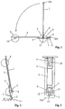
- Vehicle essentially consists of a tread plate 3, a rear wheel arrangement 4, a steerable front wheel arrangement 2 on a steering plate 7, which is supported against the tread plate via a bearing arrangement 5, one Steering device 1 and a trailing roller arrangement 6.
- the tread plate 3 serves as a supporting part for connecting the rear wheel assembly to the front wheel assembly and forms a step surface for the transport of people, for the transport of loads a loading area.
- the tread plate 3 is over the front wheel arrangement extends and has a cutout 9 through which the Project steering device 1 and / or parts of the steering plate and front wheel assembly.
- a rear wheel arrangement 4 um a generally rigid and not steered rear axle 10 rotatably mounted.
- the rear wheel assembly typically consists of one or two wheels.
- the tread plate 3 is stiffened with measures familiar to the person skilled in the art, that they take the weight of a user into account even when shaken is able to carry while driving.
- the step plate is in sketched example drawn as a flat plate, but in reality not on one limited such embodiment.
- the plate can also be in Form of a deflection-resistant lattice structure to be executed have a step surface for a user or a load on their upper side.
- the steering plate 7 is opposed by means of an annular ball bearing arrangement 5 the tread plate is supported.
- the diameter of the ball bearing arrangement 5 is larger than the diameter of the cutout 9 in the tread plate and smaller than that Diameter of the steering plate 7.
- the level of the bearing ring is in the sketch Example horizontal, but can be used to achieve special driving and steering characteristics also be slightly inclined towards the horizontal.
- the steering axis 13, around which the steering plate 7 can be rotated via the bearing arrangement 5 is then in the aligned essentially vertically.
- the steering plate 7 carries holding means for suspension a front wheel assembly 2, which is usually by a single Wheel is formed, and second holding means for hinged attachment of a steering device 1. With 8 is the fulcrum for that indicated by the curved arrow Folding movement of the steering device 1 denotes.
- the level of the bearing ring 5 is so deep that it cuts the front wheel 2. Through the deep Bearing level can also be the pivot point 8 for the folding movement of the steering device 1 be placed low, so that when folded an extremely small pack size of the vehicle, in particular perpendicular to the Step plate 3 results. Such a small pack size is shown in the sketch in FIG. 2 evident.
- Trailing roller arrangement 6 In the area of the front edge 3 / A of the tread plate 3 there is a bottom Trailing roller arrangement 6 from preferably two in the direction of travel transverse to each other spaced towing rollers provided. These drag rollers allow a transport of the folded as shown in Fig. 2 Vehicle in a pulling manner in the inclined position of the tread plate 3 of the vehicle.
- the drag rollers 6 are behind the front edge 3 / A Step plate 3 reset so that when the step plate 3 is in the vertical position The vehicle stands on the front edge of the tread plate and the drag rollers 6 are lifted off the ground. This ensures a secure leaning of the folded vehicle ensures space-saving vertical alignment.
- the grip part 1 / A of the steering device 1 projects beyond the rear wheel arrangement, so that especially for the pulling Transport of the vehicle is given a good grip position.
- the steering device can be locked in the folded position with the step plate.
- the Steering device in a composition of several tubes several Handle positions. Additional grip positions can be provided on the tread plate 3 be.
- the top view of the vehicle in the folded state according to FIG. 3 shows the pack size in the folded dimensions in the transverse dimensions Status.
- Some details of the steering arrangement can also be seen with the rotatable steering plate 7, which has a recess 11, through which the front wheel 2 protrudes.
- the cutout 9 in the tread plate 3 is preferably circular.
- the front wheel axle is designated by 12 in FIG. 3.
- FIGS 4 and 5 show some details of a preferred embodiment the bearing arrangement and the rotatable steering plate.
- the steering plate 7, which in the sketched example is designed as a flat plate, points on its underside first holding means 15 in the form of protruding downwards perpendicular to the steering plate Bearing plates with dropouts 14 open at the bottom for receiving the front wheel axle 12.
- the holding plates 15 molded together with the plate, for example, with this screwed or welded, by bending plate parts from the plate level or generated in a manner known per se to the person skilled in the art become.
- the steering plate 7 carries second holding means for attachment the steering device.
- These second holding means are, for example, two parallel, approximately triangular or trapezoidal guide plates, which each receive a tube of the steering device 1 between them.
- the second holding elements each also contain a stop element that in outlined example case as arranged between the guide plates 16, 17 Stop plate 23 is executed.
- the folding movement between the driving position and the transport position takes place in the sketched Example by a perpendicular to the guide plates 16, 17 through the space between these extending bolts 18, which in one Elongated hole of the respective tube of the steering device runs.
- the bolts 20 of the quick-action fastener slide into one Groove of the stop plate 23 and the other the lower end of the tube Steering device in a recess 22 in the steering plate.
- the bearing arrangement is in a particularly simple case as a ball bearing arrangement with a plurality of in a spacer ring relative to each other positioned bearing balls executed, the balls without specially trained Ball tracks on flat surfaces of steering plate 7 and step plate 3 be able to walk. Details of such a preferred embodiment of the bearing arrangements are described later. Of course there are A variety of known from the prior art bearing arrangements for Storage of the steering plate 7 with respect to the tread plate 3 is conceivable.
- the steering plate 7 can still move in the plane of the annular bearing arrangements by separate Guide means are guided.
- Guide means for example a circular cylindrical guide ring 28, which in a Circular groove of the steering plate 7 lies and in the circular cutout 9 of the tread plate protrudes.
- the outer diameter of the guide ring is slight smaller than the inner diameter of the circular cutout 9 of the tread plate.
- Guide rollers can be provided, which along the inner edge of the recess 9 arranged and connected to the steering plate 7 and around vertically axes running to the bearing level are rotatable.
- securing elements can be provided which are connected to the the steering plate are connected and over the edge of the cutout 9 of the tread plate to grab.
- this is a level and parallel to that Bearing level retaining ring 27 is provided, which in turn has an annular groove for the guide ring 28.
- the outer edge of the snap ring 27 protrudes beyond the edge of section 9.
- the locking ring 27 is distributed over a plurality of fasteners distributed over the inner circumference of the locking ring 29 connected to the steering plate 7 and thus ensures easy and reliable way of lifting the tread plate from the steering plate.
- FIGS. 6 and 7 show an alternative embodiment of the erection to FIGS. 4, 5 and locking the steering device outlined.
- the quick-release fastener is for fastening when erected slidable in the longitudinal direction of the tube of the steering device and moves by means of this displaceability into a recess in the stop plate on.
- the downward-facing pipe end of the steering device preferably engages again in a recess 122 of the steering plate, this recess 127 to the front shows an extension 222 through which the pipe end the steering device is pivoted.
- Other versions of the foldability the steering device and its attachment are conceivable.
- the pivot axis for the folding movement of the steering device is preferably still under the top edge of the steered wheel, so the dimensions of the folded vehicle not or not significantly the swivel mechanism are determined.
- FIG. 8 shows an advantageous embodiment of a locking ring 27 of the type shown in Fig. 4.
- the locking ring is essentially circular and has a concentric to the outer and inner circumference Ring groove 26, which is provided for receiving the guide ring 28.
- In the immediate vicinity of this annular groove 26 are several holes 29 / A for fasteners 29 (Fig. 4) is provided.
- the inner ring edge Stabilization of the ring material can be provided at these points.
- Figures 9 to 11 show details of an advantageous embodiment of a Bearing arrangement with a plurality of balls guided on a ring.
- the Ball guide consists of a spacer ring with inserted in this Centering lamellas.
- 9 is the spacer ring 30, which on the Ring circumference distributes a plurality of openings or bores 31 as Recordings for bearing balls and slots 32 between the openings Includes centering plates.
- the openings 31 are preferred regularly, i.e. offset by the same angular segments dW, distributed on the spacer ring.
- the diameter of the openings 31 is slightly larger than the diameter of the bearing balls to be used.
- the angle dS over which a slot 32 extends is advantageously 0.3 to 0.6 times, preferably 0.5 times the angular segment dW, with which the ring structure is repeated.
- dW is the same 20 ° and dS equal to 10 °. If the values for dW are significantly larger, several can be used separate slots between 2 ball receptacles can be provided with accordingly reduced angle dS.
- Centering lamellae are inserted into the slots, which preferably consist of one flat and flat material are removed and elastically deformable are. Due to the forced bend when inserted into the slots there is an elastically tensioned, self-retaining position of the slats in the Slits.
- Fig. 11 shows a composite bearing arrangement, from which also an advantageous shape of the centering lamella is evident.
- the steering plate 7 and the tread plate 3 are in the area of the bearing arrangements through the bearing balls 5 held at a distance that is determined by the ball diameter and possibly existing ball tracks is defined.
- the distance between the tarpaulin surfaces is the same the diameter of the bearing balls.
- the bearing balls are in the breakthroughs 31 of the spacer ring 30 performed in a defined mutual position.
- centering plates 34 are used, which on a Side, for example as in the sketched case between spacer ring 30 and tread plate 3 sections projecting beyond the slot width in both directions 35 have.
- the protruding sections are used for insertion of the slats and during storage as stops for the slats in the slots of the spacer ring.
- the height of the centering slats is slightly less than the diameter of the bearing balls.
- the amount of the overhang Section 35 is dimensioned so that the centering lamellae on both Sides of the spacer ring in the direction perpendicular to the plane of the spacer ring survive by approximately the same dimensions and thus at least approximately the spacer ring hold in the middle between the ball treads. For example, at a ball thickness of 4.7 mm and a thickness of the spacer ring of 1.5 mm Height of the centering lamella to 4.5 mm and the height of the protruding sections 35 selected to 1.5 mm.
- the centering plates are preferably in Adjacent slots of the spacer ring are inserted from the alternating side.
- the invention is not restricted to the exemplary embodiments described, but in various ways within the framework of professional skill changeable.
Applications Claiming Priority (2)
| Application Number | Priority Date | Filing Date | Title |
|---|---|---|---|
| DE1997157867 DE19757867A1 (de) | 1997-12-24 | 1997-12-24 | Klappbares Transportfahrzeug |
| DE19757867 | 1997-12-24 |
Publications (2)
| Publication Number | Publication Date |
|---|---|
| EP0926055A2 true EP0926055A2 (fr) | 1999-06-30 |
| EP0926055A3 EP0926055A3 (fr) | 2000-11-29 |
Family
ID=7853382
Family Applications (1)
| Application Number | Title | Priority Date | Filing Date |
|---|---|---|---|
| EP98123888A Withdrawn EP0926055A3 (fr) | 1997-12-24 | 1998-12-16 | Véhicule de transport pliable |
Country Status (2)
| Country | Link |
|---|---|
| EP (1) | EP0926055A3 (fr) |
| DE (1) | DE19757867A1 (fr) |
Cited By (9)
| Publication number | Priority date | Publication date | Assignee | Title |
|---|---|---|---|---|
| WO2001087696A1 (fr) * | 2000-05-17 | 2001-11-22 | Manfred Dellemann | Trottinette |
| GB2368324A (en) * | 2000-10-28 | 2002-05-01 | Damain Mason | Scooter provided with means to enhance manoeuverability thereof |
| KR20030013562A (ko) * | 2001-08-08 | 2003-02-15 | 김종선 | 휴대용 미니스쿠터 |
| KR100424778B1 (ko) * | 2001-02-06 | 2004-03-30 | 주식회사 휴모봇 | 주행용 보드 |
| FR2870506A1 (fr) * | 2004-05-24 | 2005-11-25 | Francis Rene Victor Bellan | Transformation d'un cycle urbain en un chariot a deux roues tractable manuellement permettant d'acceder aux transports en commun et a l'interieur des batiments |
| ITRM20090265A1 (it) * | 2009-05-25 | 2010-11-26 | Sergio Dardanelli | Monopattino elettrico pieghevole dotato di mezzi di trasporto a rotelle. |
| WO2012072893A1 (fr) * | 2010-12-02 | 2012-06-07 | Jacques Benarrouch | Trottinette triptyque pliante a roues escamotables |
| JP2014533620A (ja) * | 2011-11-18 | 2014-12-15 | ベナルッチ,ジャック | 収納可能な車輪を有する3部構成の折り畳みスクーター |
| CN114364601A (zh) * | 2019-09-06 | 2022-04-15 | 伦普希个人出行有限公司 | 装配有基于鲍登电缆的转向传动系统的车辆,用于滑板车的冲击吸收器和这样配置的滑板车 |
Citations (6)
| Publication number | Priority date | Publication date | Assignee | Title |
|---|---|---|---|---|
| FR705063A (fr) | 1930-10-25 | 1931-06-01 | Nouveau dispositif de direction pour véhicules | |
| US1853738A (en) | 1930-01-25 | 1932-04-12 | Dodgem Corp | Steering wheel drive mechanism for amusement cars |
| DE889407C (de) | 1951-08-12 | 1953-09-10 | Georg Murr | Lenkung eines Dreirad-Kleinautos mit Vorderrad-Antrieb |
| DE8401058U1 (de) | 1984-01-16 | 1984-04-26 | Grzan, Peter, 4282 Velen | Fussroller |
| DE9403582U1 (de) | 1994-03-03 | 1995-06-29 | Puky Fahrzeugfab Gmbh | Roller |
| WO1995034461A1 (fr) | 1994-05-16 | 1995-12-21 | Carlo Cianchetti | Trottinette repliable |
Family Cites Families (7)
| Publication number | Priority date | Publication date | Assignee | Title |
|---|---|---|---|---|
| DE526580C (de) * | 1931-06-08 | Paul Fuess | Laengskugellager | |
| US1326034A (en) * | 1919-12-23 | de martino | ||
| DE249432C (fr) * | ||||
| DE3008164A1 (de) * | 1980-03-04 | 1981-10-01 | Industriewerk Schaeffler Ohg, 8522 Herzogenaurach | Axialkugellager |
| GB2116495A (en) * | 1982-03-08 | 1983-09-28 | Takeshi Imai | Individual transportation vehicle |
| US4821832A (en) * | 1987-07-09 | 1989-04-18 | Patmont Steven J | Motor scooter having a foldable handle and friction drive |
| DE4440765A1 (de) * | 1994-11-15 | 1996-05-23 | Helmut Dipl Ing Wulf | Einklappbares zweiachsiges Fahrzeug |
-
1997
- 1997-12-24 DE DE1997157867 patent/DE19757867A1/de not_active Withdrawn
-
1998
- 1998-12-16 EP EP98123888A patent/EP0926055A3/fr not_active Withdrawn
Patent Citations (6)
| Publication number | Priority date | Publication date | Assignee | Title |
|---|---|---|---|---|
| US1853738A (en) | 1930-01-25 | 1932-04-12 | Dodgem Corp | Steering wheel drive mechanism for amusement cars |
| FR705063A (fr) | 1930-10-25 | 1931-06-01 | Nouveau dispositif de direction pour véhicules | |
| DE889407C (de) | 1951-08-12 | 1953-09-10 | Georg Murr | Lenkung eines Dreirad-Kleinautos mit Vorderrad-Antrieb |
| DE8401058U1 (de) | 1984-01-16 | 1984-04-26 | Grzan, Peter, 4282 Velen | Fussroller |
| DE9403582U1 (de) | 1994-03-03 | 1995-06-29 | Puky Fahrzeugfab Gmbh | Roller |
| WO1995034461A1 (fr) | 1994-05-16 | 1995-12-21 | Carlo Cianchetti | Trottinette repliable |
Cited By (11)
| Publication number | Priority date | Publication date | Assignee | Title |
|---|---|---|---|---|
| WO2001087696A1 (fr) * | 2000-05-17 | 2001-11-22 | Manfred Dellemann | Trottinette |
| GB2368324A (en) * | 2000-10-28 | 2002-05-01 | Damain Mason | Scooter provided with means to enhance manoeuverability thereof |
| KR100424778B1 (ko) * | 2001-02-06 | 2004-03-30 | 주식회사 휴모봇 | 주행용 보드 |
| KR20030013562A (ko) * | 2001-08-08 | 2003-02-15 | 김종선 | 휴대용 미니스쿠터 |
| FR2870506A1 (fr) * | 2004-05-24 | 2005-11-25 | Francis Rene Victor Bellan | Transformation d'un cycle urbain en un chariot a deux roues tractable manuellement permettant d'acceder aux transports en commun et a l'interieur des batiments |
| ITRM20090265A1 (it) * | 2009-05-25 | 2010-11-26 | Sergio Dardanelli | Monopattino elettrico pieghevole dotato di mezzi di trasporto a rotelle. |
| WO2012072893A1 (fr) * | 2010-12-02 | 2012-06-07 | Jacques Benarrouch | Trottinette triptyque pliante a roues escamotables |
| FR2968266A1 (fr) * | 2010-12-02 | 2012-06-08 | Jacques Benarrouch | Trottinette triptyque pliante a roues escamotables |
| CN104024098A (zh) * | 2010-12-02 | 2014-09-03 | 雅克·贝纳鲁什 | 具有可伸缩的轮子的三件式的折叠滑板车 |
| JP2014533620A (ja) * | 2011-11-18 | 2014-12-15 | ベナルッチ,ジャック | 収納可能な車輪を有する3部構成の折り畳みスクーター |
| CN114364601A (zh) * | 2019-09-06 | 2022-04-15 | 伦普希个人出行有限公司 | 装配有基于鲍登电缆的转向传动系统的车辆,用于滑板车的冲击吸收器和这样配置的滑板车 |
Also Published As
| Publication number | Publication date |
|---|---|
| DE19757867A1 (de) | 1999-07-01 |
| EP0926055A3 (fr) | 2000-11-29 |
Similar Documents
| Publication | Publication Date | Title |
|---|---|---|
| EP2205474B1 (fr) | Système de transport comportant notamment des palettes mobiles | |
| DE60303842T2 (de) | Klappbares Fahrrad | |
| EP3103712B1 (fr) | Scooter pliable | |
| DE2443516A1 (de) | Fahrrad, insbesondere klappfahrrad | |
| EP0955224A2 (fr) | Chariot escamotable | |
| EP0926055A2 (fr) | Véhicule de transport pliable | |
| WO2010013082A1 (fr) | Palette avec mécanisme de roulement mobile | |
| DE102018117293B4 (de) | Faltbarer Bollerwagen mit Sicherheitsbremsfunktion | |
| EP3943365A2 (fr) | Châssis pour un chariot et chariot | |
| DE102009017925A1 (de) | Fahrradanhänger mit verlängerbarer Ladefläche | |
| DE3519960C2 (fr) | ||
| DE102017108123B4 (de) | Fahrradanhänger und Vorrichtung für einen Fahrradanhänger | |
| DE202020104896U1 (de) | Transportvorrichtung | |
| DE202009005772U1 (de) | Fahrradanhänger mit verlängerbarer Ladefläche | |
| DE202019002514U1 (de) | Mehrspuriges Gefährt zur Beförderung von Lasten | |
| WO2019224111A1 (fr) | Véhicule à module de conduite et module de chargement | |
| DE202006014205U1 (de) | Rollerähnliches zusammenlegbares Sportgerät "Mini"-Tretroller | |
| EP3401119A1 (fr) | Véhicule de chargement des charges | |
| DE19700645C2 (de) | Sackkarren zum Transportieren von Lasten | |
| DE102022124205B3 (de) | Zusammenfaltbares Fahrzeug sowie System aus einem derartigen Fahrzeug und einer Tasche | |
| DE2930934C2 (de) | Parkvorrichtung für Kraftfahrzeuge | |
| DE202017100729U1 (de) | Zusammenklappbarer Transportwagen mit Transportkiste sowie zusammenlegbare Transportkiste für einen Transportwagen | |
| DE102008042994B4 (de) | Transportvorrichtung für Ballspieltor, Ballspieltor mit Transportvorrichtung und Verfahren zum Anbringen einer Transportvorrichtung an ein Ballspieltor | |
| DE102008060060A1 (de) | Transportvorrichtung für einen Patienten | |
| DE102007011701A1 (de) | Verfahrbare Transportvorrichtung und Anordnung mit zwei solchen Transportvorrichtungen |
Legal Events
| Date | Code | Title | Description |
|---|---|---|---|
| PUAI | Public reference made under article 153(3) epc to a published international application that has entered the european phase |
Free format text: ORIGINAL CODE: 0009012 |
|
| AK | Designated contracting states |
Kind code of ref document: A2 Designated state(s): AT BE CH CY DE DK ES FI FR GB GR IE IT LI LU MC NL PT SE |
|
| AX | Request for extension of the european patent |
Free format text: AL;LT;LV;MK;RO;SI |
|
| RIC1 | Information provided on ipc code assigned before grant |
Free format text: 7B 62K 3/00 A, 7B 62K 15/00 B, 7B 62K 21/00 B |
|
| PUAL | Search report despatched |
Free format text: ORIGINAL CODE: 0009013 |
|
| AK | Designated contracting states |
Kind code of ref document: A3 Designated state(s): AT BE CH CY DE DK ES FI FR GB GR IE IT LI LU MC NL PT SE |
|
| AX | Request for extension of the european patent |
Free format text: AL;LT;LV;MK;RO;SI |
|
| AKX | Designation fees paid | ||
| REG | Reference to a national code |
Ref country code: DE Ref legal event code: 8566 |
|
| STAA | Information on the status of an ep patent application or granted ep patent |
Free format text: STATUS: THE APPLICATION IS DEEMED TO BE WITHDRAWN |
|
| 18D | Application deemed to be withdrawn |
Effective date: 20010702 |