EP0926055A2 - Foldable transport vehicle - Google Patents
Foldable transport vehicle Download PDFInfo
- Publication number
- EP0926055A2 EP0926055A2 EP98123888A EP98123888A EP0926055A2 EP 0926055 A2 EP0926055 A2 EP 0926055A2 EP 98123888 A EP98123888 A EP 98123888A EP 98123888 A EP98123888 A EP 98123888A EP 0926055 A2 EP0926055 A2 EP 0926055A2
- Authority
- EP
- European Patent Office
- Prior art keywords
- plate
- steering
- vehicle according
- steering device
- bearing
- Prior art date
- Legal status (The legal status is an assumption and is not a legal conclusion. Google has not performed a legal analysis and makes no representation as to the accuracy of the status listed.)
- Withdrawn
Links
Images


Classifications
-
- B—PERFORMING OPERATIONS; TRANSPORTING
- B62—LAND VEHICLES FOR TRAVELLING OTHERWISE THAN ON RAILS
- B62K—CYCLES; CYCLE FRAMES; CYCLE STEERING DEVICES; RIDER-OPERATED TERMINAL CONTROLS SPECIALLY ADAPTED FOR CYCLES; CYCLE AXLE SUSPENSIONS; CYCLE SIDE-CARS, FORECARS, OR THE LIKE
- B62K3/00—Bicycles
- B62K3/002—Bicycles without a seat, i.e. the rider operating the vehicle in a standing position, e.g. non-motorized scooters; non-motorized scooters with skis or runners
-
- B—PERFORMING OPERATIONS; TRANSPORTING
- B62—LAND VEHICLES FOR TRAVELLING OTHERWISE THAN ON RAILS
- B62K—CYCLES; CYCLE FRAMES; CYCLE STEERING DEVICES; RIDER-OPERATED TERMINAL CONTROLS SPECIALLY ADAPTED FOR CYCLES; CYCLE AXLE SUSPENSIONS; CYCLE SIDE-CARS, FORECARS, OR THE LIKE
- B62K15/00—Collapsible or foldable cycles
- B62K15/006—Collapsible or foldable cycles the frame being foldable
Definitions
- the invention relates to a foldable transport vehicle according to the preamble of claim 1.
- Foldable vehicles of this type are particularly in the inner city area due to the possibility of carrying the vehicle when folded or to be dragged into buildings or public transport or in To accommodate storage space of a motor vehicle, a considerable advantage. Little one and manoeuvrable vehicles of this type can also be used advantageously in large areas Companies or facilities such as airports.
- a steering column is typically used in such foldable transport vehicles guided in a steering head, which also mechanical means for Folding the steering device against a step plate with a usually non-steerable rear wheel.
- Such transport vehicles are, for example known from G 84 01 058.4 U1 or DE 94 03 582 U1.
- One out the arrangement known from WO 95/34461 A1 provides one with struts and stiffeners significantly more complex steering device in which the steerability of the front wheel by storing extensions of the front wheel axle in Guide slots of extensions of the tread plate is realized.
- the object of the present invention is a foldable transport vehicle indicate that with little mechanical effort an uncomplicated enables and safe operation in the driving state and in the merged Condition of a small pack size and easy handling offers.
- the steering plate used according to the invention allows easy attachment both the front wheel and the steering device on appropriate holding means and at the same time offers thanks to the large diameter of the bearing ring a stable mounting of the steering arrangement in all driving situations.
- the low position of the bearing level enables positioning close to the wheel axis a folding device for the steering device, from which a particularly inexpensive Pack size results.
- the steering device is firmly connected to the steering plate, so that there is direct steering.
- Under the tread plate is a front wheel arrangement understood and supporting part of the vehicle connecting rear wheel arrangement, which is not necessarily the shape of a flat or flat one Has plate, but in particular also has stiffeners and also as Lightweight lattice structure or the like. Can be carried out.
- a step plate also serves as a step surface for the transport of loads as a loading area.
- the bearing preferably comprises a ball bearing with between the bearing surfaces running bearing balls, but can also be equipped with bearing rollers or be designed as a plain bearing.
- the bearing surface of the steering plate is doing so under the bearing surface of the tread plate.
- the steering plate can be in one piece be executed, but can also be composed of several components be.
- the tread plate shows a section within the storage area, which is preferably is circular.
- securing means are advantageously provided on the tread plate, which are connected to the steering plate by the cutout of the tread plate and reach over the edge of the cutout of the tread plate.
- Wheel suspensions in rotatable plates are known per se, for example from US 1,853,738, FR 705 063 or DE 889 407, but no folding of the vehicle is provided or is possible.
- the steering engages, for example via a chain drive, on a ring in the storage area.
- the steering plate against displacements parallel to the plane to hold and / or guide the bearing ring.
- a circular cylindrical guide ring be connected to the steering plate and through the cutout of the tread plate protrude through.
- the outer diameter of the guide ring is slightly smaller than the inside diameter of the circular cutout of the tread plate.
- the guide ring and the locking ring together also provide protection against the penetration of dirt into the bearing arrangement.
- the steering plate is advantageously designed as a flat plate, which a Has recess through which the front wheel protrudes.
- the holding devices for the folding steering device advantageously point for the folding movement in the direction of the driving position Stop elements on which the steering device for driving is determined, especially using quick release fasteners.
- the lateral distance of the second holding means for the steering device from the steering axis is preferably greater than the corresponding distance first holding means so that the steering device on the holding means on the Steering plate is stably supported and the lever arm for the transmission of the Steering forces on the steering plate is large.
- the steering plate can also be a support for one to be provided on the front wheel Have brake, in particular a so-called V-brake. Is preferred a brake assembly, in particular a drum brake assembly on the Rear wheel arrangement provided.
- a brake assembly in particular a drum brake assembly on the Rear wheel arrangement provided.
- the trailing rollers are preferably behind the The front edge of the step plate is set back so that the folded one Vehicle runs on the one hand in an oblique pull position on the rollers and on the other hand, parked in the upright position of the tread on the front edge can be without the trailing rollers touching the base.
- the Front edge of the tread plate can advantageously be made with an elastic material in the form of a rubber strip, plastic lip or the like. To be provided Risk of damage to objects or when the vehicle is parked to reduce the footprint.
- the vehicle can be provided with a motor drive, which is preferably via a Friction roller on a tire tread or preferably over a gear, Belt or chain drive engages a wheel assembly.
- a motor module that can be attached as an additional device in the area of the driven wheel arranged.
- the arrangement of the motor drive is constructive particularly easy on the rear wheel arrangement.
- Through the Wheel suspension on the steering plate is advantageously also an arrangement a motor drive on the steering plate possible, which in a corresponding Acts on the front wheel.
- the arrangement of the motor drive at the front wheel arrangement is favorable for the weight distribution sluggish transport of the folded vehicle.
- Vehicle essentially consists of a tread plate 3, a rear wheel arrangement 4, a steerable front wheel arrangement 2 on a steering plate 7, which is supported against the tread plate via a bearing arrangement 5, one Steering device 1 and a trailing roller arrangement 6.
- the tread plate 3 serves as a supporting part for connecting the rear wheel assembly to the front wheel assembly and forms a step surface for the transport of people, for the transport of loads a loading area.
- the tread plate 3 is over the front wheel arrangement extends and has a cutout 9 through which the Project steering device 1 and / or parts of the steering plate and front wheel assembly.
- a rear wheel arrangement 4 um a generally rigid and not steered rear axle 10 rotatably mounted.
- the rear wheel assembly typically consists of one or two wheels.
- the tread plate 3 is stiffened with measures familiar to the person skilled in the art, that they take the weight of a user into account even when shaken is able to carry while driving.
- the step plate is in sketched example drawn as a flat plate, but in reality not on one limited such embodiment.
- the plate can also be in Form of a deflection-resistant lattice structure to be executed have a step surface for a user or a load on their upper side.
- the steering plate 7 is opposed by means of an annular ball bearing arrangement 5 the tread plate is supported.
- the diameter of the ball bearing arrangement 5 is larger than the diameter of the cutout 9 in the tread plate and smaller than that Diameter of the steering plate 7.
- the level of the bearing ring is in the sketch Example horizontal, but can be used to achieve special driving and steering characteristics also be slightly inclined towards the horizontal.
- the steering axis 13, around which the steering plate 7 can be rotated via the bearing arrangement 5 is then in the aligned essentially vertically.
- the steering plate 7 carries holding means for suspension a front wheel assembly 2, which is usually by a single Wheel is formed, and second holding means for hinged attachment of a steering device 1. With 8 is the fulcrum for that indicated by the curved arrow Folding movement of the steering device 1 denotes.
- the level of the bearing ring 5 is so deep that it cuts the front wheel 2. Through the deep Bearing level can also be the pivot point 8 for the folding movement of the steering device 1 be placed low, so that when folded an extremely small pack size of the vehicle, in particular perpendicular to the Step plate 3 results. Such a small pack size is shown in the sketch in FIG. 2 evident.
- Trailing roller arrangement 6 In the area of the front edge 3 / A of the tread plate 3 there is a bottom Trailing roller arrangement 6 from preferably two in the direction of travel transverse to each other spaced towing rollers provided. These drag rollers allow a transport of the folded as shown in Fig. 2 Vehicle in a pulling manner in the inclined position of the tread plate 3 of the vehicle.
- the drag rollers 6 are behind the front edge 3 / A Step plate 3 reset so that when the step plate 3 is in the vertical position The vehicle stands on the front edge of the tread plate and the drag rollers 6 are lifted off the ground. This ensures a secure leaning of the folded vehicle ensures space-saving vertical alignment.
- the grip part 1 / A of the steering device 1 projects beyond the rear wheel arrangement, so that especially for the pulling Transport of the vehicle is given a good grip position.
- the steering device can be locked in the folded position with the step plate.
- the Steering device in a composition of several tubes several Handle positions. Additional grip positions can be provided on the tread plate 3 be.
- the top view of the vehicle in the folded state according to FIG. 3 shows the pack size in the folded dimensions in the transverse dimensions Status.
- Some details of the steering arrangement can also be seen with the rotatable steering plate 7, which has a recess 11, through which the front wheel 2 protrudes.
- the cutout 9 in the tread plate 3 is preferably circular.
- the front wheel axle is designated by 12 in FIG. 3.
- FIGS 4 and 5 show some details of a preferred embodiment the bearing arrangement and the rotatable steering plate.
- the steering plate 7, which in the sketched example is designed as a flat plate, points on its underside first holding means 15 in the form of protruding downwards perpendicular to the steering plate Bearing plates with dropouts 14 open at the bottom for receiving the front wheel axle 12.
- the holding plates 15 molded together with the plate, for example, with this screwed or welded, by bending plate parts from the plate level or generated in a manner known per se to the person skilled in the art become.
- the steering plate 7 carries second holding means for attachment the steering device.
- These second holding means are, for example, two parallel, approximately triangular or trapezoidal guide plates, which each receive a tube of the steering device 1 between them.
- the second holding elements each also contain a stop element that in outlined example case as arranged between the guide plates 16, 17 Stop plate 23 is executed.
- the folding movement between the driving position and the transport position takes place in the sketched Example by a perpendicular to the guide plates 16, 17 through the space between these extending bolts 18, which in one Elongated hole of the respective tube of the steering device runs.
- the bolts 20 of the quick-action fastener slide into one Groove of the stop plate 23 and the other the lower end of the tube Steering device in a recess 22 in the steering plate.
- the bearing arrangement is in a particularly simple case as a ball bearing arrangement with a plurality of in a spacer ring relative to each other positioned bearing balls executed, the balls without specially trained Ball tracks on flat surfaces of steering plate 7 and step plate 3 be able to walk. Details of such a preferred embodiment of the bearing arrangements are described later. Of course there are A variety of known from the prior art bearing arrangements for Storage of the steering plate 7 with respect to the tread plate 3 is conceivable.
- the steering plate 7 can still move in the plane of the annular bearing arrangements by separate Guide means are guided.
- Guide means for example a circular cylindrical guide ring 28, which in a Circular groove of the steering plate 7 lies and in the circular cutout 9 of the tread plate protrudes.
- the outer diameter of the guide ring is slight smaller than the inner diameter of the circular cutout 9 of the tread plate.
- Guide rollers can be provided, which along the inner edge of the recess 9 arranged and connected to the steering plate 7 and around vertically axes running to the bearing level are rotatable.
- securing elements can be provided which are connected to the the steering plate are connected and over the edge of the cutout 9 of the tread plate to grab.
- this is a level and parallel to that Bearing level retaining ring 27 is provided, which in turn has an annular groove for the guide ring 28.
- the outer edge of the snap ring 27 protrudes beyond the edge of section 9.
- the locking ring 27 is distributed over a plurality of fasteners distributed over the inner circumference of the locking ring 29 connected to the steering plate 7 and thus ensures easy and reliable way of lifting the tread plate from the steering plate.
- FIGS. 6 and 7 show an alternative embodiment of the erection to FIGS. 4, 5 and locking the steering device outlined.
- the quick-release fastener is for fastening when erected slidable in the longitudinal direction of the tube of the steering device and moves by means of this displaceability into a recess in the stop plate on.
- the downward-facing pipe end of the steering device preferably engages again in a recess 122 of the steering plate, this recess 127 to the front shows an extension 222 through which the pipe end the steering device is pivoted.
- Other versions of the foldability the steering device and its attachment are conceivable.
- the pivot axis for the folding movement of the steering device is preferably still under the top edge of the steered wheel, so the dimensions of the folded vehicle not or not significantly the swivel mechanism are determined.
- FIG. 8 shows an advantageous embodiment of a locking ring 27 of the type shown in Fig. 4.
- the locking ring is essentially circular and has a concentric to the outer and inner circumference Ring groove 26, which is provided for receiving the guide ring 28.
- In the immediate vicinity of this annular groove 26 are several holes 29 / A for fasteners 29 (Fig. 4) is provided.
- the inner ring edge Stabilization of the ring material can be provided at these points.
- Figures 9 to 11 show details of an advantageous embodiment of a Bearing arrangement with a plurality of balls guided on a ring.
- the Ball guide consists of a spacer ring with inserted in this Centering lamellas.
- 9 is the spacer ring 30, which on the Ring circumference distributes a plurality of openings or bores 31 as Recordings for bearing balls and slots 32 between the openings Includes centering plates.
- the openings 31 are preferred regularly, i.e. offset by the same angular segments dW, distributed on the spacer ring.
- the diameter of the openings 31 is slightly larger than the diameter of the bearing balls to be used.
- the angle dS over which a slot 32 extends is advantageously 0.3 to 0.6 times, preferably 0.5 times the angular segment dW, with which the ring structure is repeated.
- dW is the same 20 ° and dS equal to 10 °. If the values for dW are significantly larger, several can be used separate slots between 2 ball receptacles can be provided with accordingly reduced angle dS.
- Centering lamellae are inserted into the slots, which preferably consist of one flat and flat material are removed and elastically deformable are. Due to the forced bend when inserted into the slots there is an elastically tensioned, self-retaining position of the slats in the Slits.
- Fig. 11 shows a composite bearing arrangement, from which also an advantageous shape of the centering lamella is evident.
- the steering plate 7 and the tread plate 3 are in the area of the bearing arrangements through the bearing balls 5 held at a distance that is determined by the ball diameter and possibly existing ball tracks is defined.
- the distance between the tarpaulin surfaces is the same the diameter of the bearing balls.
- the bearing balls are in the breakthroughs 31 of the spacer ring 30 performed in a defined mutual position.
- centering plates 34 are used, which on a Side, for example as in the sketched case between spacer ring 30 and tread plate 3 sections projecting beyond the slot width in both directions 35 have.
- the protruding sections are used for insertion of the slats and during storage as stops for the slats in the slots of the spacer ring.
- the height of the centering slats is slightly less than the diameter of the bearing balls.
- the amount of the overhang Section 35 is dimensioned so that the centering lamellae on both Sides of the spacer ring in the direction perpendicular to the plane of the spacer ring survive by approximately the same dimensions and thus at least approximately the spacer ring hold in the middle between the ball treads. For example, at a ball thickness of 4.7 mm and a thickness of the spacer ring of 1.5 mm Height of the centering lamella to 4.5 mm and the height of the protruding sections 35 selected to 1.5 mm.
- the centering plates are preferably in Adjacent slots of the spacer ring are inserted from the alternating side.
- the invention is not restricted to the exemplary embodiments described, but in various ways within the framework of professional skill changeable.
Abstract
Description
Die Erfindung betrifft ein klappbares Transportfahrzeug nach dem Oberbegriff
des Patentanspruchs 1.The invention relates to a foldable transport vehicle according to the preamble
of
Klappbare Fahrzeuge dieser Art sind insbesondere im innerstädtischen Bereich durch die Möglichkeit, das Fahrzeug in zusammengeklapptem Zustand tragend oder ziehend in Gebäude oder öffentliche Verkehrsmittel mitzunehmen oder im Stauraum eines Kraftfahrzeugs unterzubringen, von erheblichem Vorteil. Kleine und wendige Fahrzeuge solcher Art sind auch vorteilhaft einsetzbar in großräumigen Betrieben oder Einrichtungen wie Flughäfen.Foldable vehicles of this type are particularly in the inner city area due to the possibility of carrying the vehicle when folded or to be dragged into buildings or public transport or in To accommodate storage space of a motor vehicle, a considerable advantage. Little one and manoeuvrable vehicles of this type can also be used advantageously in large areas Companies or facilities such as airports.
Typischerweise ist bei derartigen klappbaren Transportfahrzeugen eine Lenksäule in einem Lenkkopf geführt, der zugleich auch mechanische Mittel zum Klappen der Lenkvorrichtung gegenüber einer Trittplatte mit einem üblicherweise nicht lenkbaren Hinterrad trägt. Solche Transportfahrzeuge sind beispielsweise bekannt aus G 84 01 058.4 U1 oder DE 94 03 582 U1. Eine aus der WO 95/34461 A1 bekannte Anordnung sieht eine mit Streben und Versteifungen deutlich aufwendigere Lenkvorrichtung vor, bei welcher die Lenkbarkeit des Vorderrades durch Lagerung von Verlängerungen der Vorderradachse in Führungsschlitzen von Verlängerungen der Trittplatte realisiert ist.A steering column is typically used in such foldable transport vehicles guided in a steering head, which also mechanical means for Folding the steering device against a step plate with a usually non-steerable rear wheel. Such transport vehicles are, for example known from G 84 01 058.4 U1 or DE 94 03 582 U1. One out the arrangement known from WO 95/34461 A1 provides one with struts and stiffeners significantly more complex steering device in which the steerability of the front wheel by storing extensions of the front wheel axle in Guide slots of extensions of the tread plate is realized.
Der vorliegenden Erfindung liegt die Aufgabe zugrunde, ein klappbares Transportfahrzeug anzugeben, daß bei geringem mechanischem Aufwand einen unkomplizierten und sicheren Betrieb im Fahrzustand ermöglicht und im zusammengelegten Zustand ein geringes Packmaß und eine gute Handhabbarkeit bietet.The object of the present invention is a foldable transport vehicle indicate that with little mechanical effort an uncomplicated enables and safe operation in the driving state and in the merged Condition of a small pack size and easy handling offers.
Die Erfindung ist im Patentanspruch 1 beschrieben. Die Unteransprüche enthalten
vorteilhafte Ausgestaltungen und Weiterbildungen der Erfindung.The invention is described in
Die erfindungsgemäß eingesetzte Lenkplatte erlaubt eine einfache Befestigung sowohl des Vorderrads als auch der Lenkvorrichtung an entsprechenden Haltemitteln und bietet dabei gleichzeitig durch den großen Durchmesser des Lagerrings eine in allen Fahrsituationen stabile Lagerung der Lenkanordnung. Die tiefe Lage der Lagerebene ermöglicht eine radachsnahe Positionierung einer Klappvorrichtung für die Lenkvorrichtung, woraus ein besonders günstiges Packmaß resultiert. Hinsichtlich der lenkenden Bewegung des Vorderrads in Fahrstellung ist die Lenkvorrichtung fest mit der Lenkplatte verbunden, so daß eine Direktlenkung gegeben ist. Unter Trittplatte sei ein Vorderradanordnung und Hinterradanordnung verbindender tragender Teil des Fahrzeugs verstanden, der nicht notwendigerweise die Form einer flachen oder ebenen Platte hat, sondern insbesondere auch Versteifungen aufweist und auch als Leichtbau-Gitterkonstruktion oder dgl. ausgeführt sein kann. Für den Personentransport dient eine solche Trittplatte zugleich als Trittfläche, für den Lastentransport als Ladefläche.The steering plate used according to the invention allows easy attachment both the front wheel and the steering device on appropriate holding means and at the same time offers thanks to the large diameter of the bearing ring a stable mounting of the steering arrangement in all driving situations. The low position of the bearing level enables positioning close to the wheel axis a folding device for the steering device, from which a particularly inexpensive Pack size results. Regarding the steering movement of the front wheel in the driving position, the steering device is firmly connected to the steering plate, so that there is direct steering. Under the tread plate is a front wheel arrangement understood and supporting part of the vehicle connecting rear wheel arrangement, which is not necessarily the shape of a flat or flat one Has plate, but in particular also has stiffeners and also as Lightweight lattice structure or the like. Can be carried out. For passenger transportation such a step plate also serves as a step surface for the transport of loads as a loading area.
Für die drehbare Lagerung der Lenkplatte gegenüber der Trittplatte weisen beide genannten Platten einander zugewandte ringförmige Lagerflächen auf. Die Lagerung umfaßt vorzugsweise ein Kugellager mit zwischen den Lagerflächen laufenden Lagerkugeln, kann jedoch auch mit Lagerrollen ausgestattet oder als Gleitlager ausgeführt sein. Die Lagerlauffläche der Lenkplatte liegt dabei unter der Lagerlauffläche der Trittplatte. Die Lenkplatte kann einstückig ausgeführt sein, kann jedoch auch aus mehreren Bauteilen zusammengesetzt sein.For the rotatable mounting of the steering plate opposite the step plate both mentioned plates on mutually facing annular bearing surfaces. The bearing preferably comprises a ball bearing with between the bearing surfaces running bearing balls, but can also be equipped with bearing rollers or be designed as a plain bearing. The bearing surface of the steering plate is doing so under the bearing surface of the tread plate. The steering plate can be in one piece be executed, but can also be composed of several components be.
Die Trittplatte zeigt innerhalb des Lagerbereichs einen Ausschnitt, der vorzugsweise kreisförmig ist. Zur Sicherung der Lenkplatte in ihrer Position bezüglich der Trittplatte sind vorteilhafterweise Sicherungsmittel vorgesehen, welche durch den Ausschnitt der Trittplatte mit der Lenkplatte verbunden sind und über den Rand des Ausschnitts der Trittplatte greifen. Diese Sicherungsmittel sind vorteilhafterweise als flacher, zu der Lagerebene paralleler Sicherungsring ausgeführt.The tread plate shows a section within the storage area, which is preferably is circular. To secure the steering plate in position with respect securing means are advantageously provided on the tread plate, which are connected to the steering plate by the cutout of the tread plate and reach over the edge of the cutout of the tread plate. These safeguards are advantageously as a flat, parallel to the bearing plane locking ring executed.
Radaufhängungen in drehbaren Platten, deren Drehlagerebene das Vorderrad schneidet sind an sich bekannt, beispielsweise aus US 1,853,738, FR 705 063 oder DE 889 407, wobei aber kein Zusammenklappen des Fahrzeugs vorgesehen oder möglich ist. Die Lenkung greift, beispielsweise über einen Kettentrieb, an einem Ring im Lagerbereich an. Demgegenüber zeigt das erfindungsgemäße Fahrzeug mit der Direktlenkung ein für den Benutzer eines Leichtfahrzeugs, der auf der Trittplatte steht, vertrautes und dadurch vorteilhaftes Lenk- und Fahrverhalten.Wheel suspensions in rotatable plates, the pivot level of which is the front wheel cuts are known per se, for example from US 1,853,738, FR 705 063 or DE 889 407, but no folding of the vehicle is provided or is possible. The steering engages, for example via a chain drive, on a ring in the storage area. In contrast, shows the invention Vehicle with direct steering on for the user of a light vehicle, who stands on the step plate, familiar and therefore advantageous steering and Driving behavior.
Je nach Art der Ausführung der Lageranordnung kann es noch zweckmäßig oder erforderlich sein, die Lenkplatte gegen Verschiebungen parallel zur Ebene des Lagerrings zu halten und/oder zu führen. Hierfür kann beispielsweise in einer mechanisch einfachen Ausführungsform ein kreiszylindrischer Führungsring mit der Lenkplatte verbunden sein und durch den Ausschnitt der Trittplatte hindurchragen. Der Außendurchmesser des Führungsrings ist geringfügig kleiner als der Innendurchmesser des kreisförmigen Ausschnitts der Trittplatte. Führungsring und Sicherungsring bilden zusammen auch einen Schutz gegen das Eindringen vom Schmutz in die Lageranordnung. Alternativ oder zusätzlich dazu können auch mehrere in den Ausschnitt der Trittplatte ragende, und parallel zur Lenkachse drehbare und am Innenrand des Ausschnitts der Trittplatte anliegende Rollen als Führungselemente mit der Lenkplatte verbunden sein.Depending on the type of design of the bearing arrangement, it can still be useful or may be required, the steering plate against displacements parallel to the plane to hold and / or guide the bearing ring. For example, in a mechanically simple embodiment, a circular cylindrical guide ring be connected to the steering plate and through the cutout of the tread plate protrude through. The outer diameter of the guide ring is slightly smaller than the inside diameter of the circular cutout of the tread plate. The guide ring and the locking ring together also provide protection against the penetration of dirt into the bearing arrangement. Alternatively or additionally In addition, several can protrude into the cutout of the tread plate, and parallel rotatable to the steering axis and on the inner edge of the cutout of the step plate adjacent roles as guide elements to be connected to the steering plate.
Die Lenkplatte ist vorteilhafterweise als ebene Platte ausgeführt, welche eine Aussparung aufweist, durch welche das Vorderrad hindurchragt. Vorzugsweise sind erste Haltemittel für die Aufhängung des Vorderrades in der Art von nach unten abstehenden Platten mit Ausfallenden zur Aufnahme einer Vorderradachse und durch den Ausschnitt in der Trittplatte nach oben weisende zweite Haltemittel zur klappbaren Befestigung einer Lenkvorrichtung auf der Lenkplatte vorgesehen. Die Halteeinrichtungen für die klappbare Lenkvorrichtung weisen vorteilhafterweise für die Klappbewegung in Richtung der Fahrstellung Anschlagelemente auf, an welchen die Lenkvorrichtung für den Fahrbetrieb festgelegt wird, insbesondere unter Verwendung von Schnellspannverschlüssen. Der seitliche Abstand der zweiten Haltemitteln für die Lenkvorrichtung von der Lenkachse ist vorzugsweise größer als der entsprechende Abstand der ersten Haltemittel, so daß die Lenkvorrichtung über die Haltemittel auf der Lenkplatte stabil abgestützt ist und der Hebelarm für die Übertragung der Lenkkräfte auf die Lenkplatte groß ist.The steering plate is advantageously designed as a flat plate, which a Has recess through which the front wheel protrudes. Preferably are first holding devices for the suspension of the front wheel in the manner of after plates protruding below with dropouts to accommodate a front wheel axle and through the cutout in the tread plate the second one pointing upwards Holding means for the foldable fastening of a steering device on the steering plate intended. The holding devices for the folding steering device advantageously point for the folding movement in the direction of the driving position Stop elements on which the steering device for driving is determined, especially using quick release fasteners. The lateral distance of the second holding means for the steering device from the steering axis is preferably greater than the corresponding distance first holding means so that the steering device on the holding means on the Steering plate is stably supported and the lever arm for the transmission of the Steering forces on the steering plate is large.
Die Lenkplatte kann auch eine Abstützung für eine am Vorderrad vorzusehende Bremse, insbesondere eine sogenannte V-Bremse aufweisen. Bevorzugt ist eine Bremsanordnung insbesondere eine Trommelbremsanordnung an der Hinterradanordnung vorgesehen. Durch im Bereich der Vorderkante der Trittplatte angeordnete Schlepprollen kann das Fahrzeug in zusammengeklapptem Zustand auch gezogen werden. Die Schlepprollen sind vorzugsweise hinter die Vorderkante der Trittplatte zurückgesetzt, so daR das zusammengeklappte Fahrzeug zum einen in einer schrägen Ziehposition auf den Rollen läuft und zum anderen in aufrechter Position der Trittfläche auf der Vorderkante abgestellt werden kann, ohne daß die Schlepprollen die Standfläche berühren. Die Vorderkante der Trittplatte kann vorteilhafterweise mit einem elastischen Material in Form einer Gummileiste, Kunststofflippe oder dgl. versehen sein, um die Gefahr von Beschädigungen an Gegenständen oder bei aufgestelltem Fahrzeug an der Stellfläche zu verringern.The steering plate can also be a support for one to be provided on the front wheel Have brake, in particular a so-called V-brake. Is preferred a brake assembly, in particular a drum brake assembly on the Rear wheel arrangement provided. Through in the area of the front edge of the step plate arranged trailing rollers can the vehicle in folded Condition also be drawn. The trailing rollers are preferably behind the The front edge of the step plate is set back so that the folded one Vehicle runs on the one hand in an oblique pull position on the rollers and on the other hand, parked in the upright position of the tread on the front edge can be without the trailing rollers touching the base. The Front edge of the tread plate can advantageously be made with an elastic material in the form of a rubber strip, plastic lip or the like. To be provided Risk of damage to objects or when the vehicle is parked to reduce the footprint.
Für die Überbrückung größerer Distanzen, insbesondere bei Einsatz des Fahrzeugs im Freizeitbereich, oder für den Transport von Lasten, kann das Fahrzeug mit einem motorischen Antrieb versehen sein, der vorzugsweise über eine Reibrolle auf einer Reifenlauffläche oder vorzugsweise über einen Zahnrad-, Riemen- oder Kettenantrieb an einer Radanordnung angreift. Hierzu wird vorzugsweise ein als Zusatzgerät anbaubares Motormodul lösbar im Bereich des angetriebenen Rades angeordnet. Die Anordnung des Motorantriebs ist konstruktiv besonders einfach an der Hinterradanordnung möglich. Durch die Radaufhängung an der Lenkplatte ist vorteilhatterweise auch eine Anordnung eines motorischen Antriebs auf der Lenkplatte möglich, welcher in entsprechender Weise auf das Vorderrad wirkt. Die Anordnung des Motorantriebs bei der Vorderradanordnung ist wegen der Gewichtsverteilung günstig für den schleppenden Transport des zusammengeklappten Fahrzeugs.For bridging larger distances, especially when using the vehicle in the leisure area, or for the transport of loads, the vehicle can be provided with a motor drive, which is preferably via a Friction roller on a tire tread or preferably over a gear, Belt or chain drive engages a wheel assembly. This is preferred a motor module that can be attached as an additional device in the area of the driven wheel arranged. The arrangement of the motor drive is constructive particularly easy on the rear wheel arrangement. Through the Wheel suspension on the steering plate is advantageously also an arrangement a motor drive on the steering plate possible, which in a corresponding Acts on the front wheel. The arrangement of the motor drive at the front wheel arrangement is favorable for the weight distribution sluggish transport of the folded vehicle.
Die Erfindung ist nachfolgend anhand von bevorzugten Ausführungsbeispielen und unter Bezugnahme auf die Abbildungen noch eingehend veranschaulicht. Dabei zeigt:
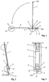
- Fig. 1
- eine schematisch vereinfachte Skizze eines erfindungsgemäßen Fahrzeugs in Seitenansicht
- Fig. 2
- das Fahrzeug nach Fig. 1 zusammengeklappt in Ziehstellung
- Fig. 3
- das Fahrzeug nach Fig. 1 zusammengeklappt in Draufsicht auf die Trittplatte
- Fig. 4
- die Lenkplatte mit Einzelheiten
- Fig. 5
- eine Draufsicht auf die Lenkplatte nach Fig. 4
- Fig. 6, 7
- eine alternative Ausführung zu Fig. 4 und 5
- Fig. 8
- einen Haltering für die Lenkplatte
- Fig. 9
- einen Distanzring für die Lageranordnung
- Fig. 10
- einen vergrößerten Ausschnitt aus Fig. 9
- Fig. 11
- einen Ausschnitt der Lageranordnung
- Fig. 1
- a schematically simplified sketch of a vehicle according to the invention in side view
- Fig. 2
- the vehicle of FIG. 1 folded in the pull position
- Fig. 3
- the vehicle of FIG. 1 folded in plan view of the tread plate
- Fig. 4
- the steering plate with details
- Fig. 5
- 4 shows a plan view of the steering plate according to FIG. 4
- 6, 7
- an alternative embodiment to FIGS. 4 and 5
- Fig. 8
- a retaining ring for the steering plate
- Fig. 9
- a spacer ring for the bearing assembly
- Fig. 10
- FIG. 9 shows an enlarged detail from FIG. 9
- Fig. 11
- a section of the bearing arrangement
Das in Fig. 1 in stark vereinfachter Darstellung skizzierte erfindungsgemäße
Fahrzeug besteht im wesentlichen aus einer Trittplatte 3, einer Hinterradanordnung
4, einer lenkbaren Vorderradanordnung 2 auf einer Lenkplatte 7,
die über eine Lageranordnung 5 gegen die Trittplatte abgestützt ist, einer
Lenkvorrichtung 1 sowie einer Schlepprollenanordnung 6. Die Trittplatte 3 dient
als tragendes Teil zur Verbindung der Hinterradanordnung mit der Vorderradanordnung
und bildet für den Personentransport eine Trittfläche, für den Lastentransport
eine Ladefläche. Die Trittplatte 3 ist über die Vorderradanordnung
hinaus verlängert und weist einen Ausschnitt 9 auf, durch welche die
Lenkvorrichtung 1 und/oder Teile der Lenkplatte und Vorderradanordnung hindurchragen.
Im hinteren Teil der Trittplatte ist eine Hinterradanordnung 4 um
eine im Regelfall starre und nicht gelenkte Hinterachse 10 drehbar gelagert.
Die Hinterradanordnung besteht typischerweise aus einem oder zwei Rädern.
Die Trittplatte 3 ist mit dem Fachmann geläufigen Maßnahmen soweit versteift,
daß sie das Gewicht eines Benutzers auch unter Berücksichtigung von Erschütterungen
im Fahrbetrieb zu tragen im Stande ist. Die Trittplatte ist im
skizzierten Beispiel als ebene Platte gezeichnet, im Realfall aber nicht auf eine
solche Ausführungsform beschränkt. Insbesondere kann die Platte auch in
Form einer durchbiegungssteifen Gitterkonstruktion ausgeführt sein und an
ihrer Oberseite eine Trittfläche für einen Benutzer oder eine Last aufweisen. The sketched in Fig. 1 in a highly simplified representation according to the invention
Vehicle essentially consists of a
Die Lenkplatte 7 ist mittels einer ringförmigen Kugellageranordnung 5 gegen
die Trittplatte abgestützt. Der Durchmesser der Kugellageranordnung 5 ist größer
als der Durchmesser des Ausschnitts 9 in der Trittplatte und kleiner als der
Durchmesser der Lenkplatte 7. Die Ebene des Lagerrings ist im skizzierten
Beispielsfall horizontal, kann aber zur Erzielung besonderer Fahr- und Lenkeigenschaften
auch gegen die Horizontale leicht geneigt sein. Die Lenkachse 13,
um welche die Lenkplatte 7 über die Lageranordnung 5 drehbar ist, ist dann im
wesentlichen vertikal ausgerichtet. Die Lenkplatte 7 trägt Haltemittel zur Aufhängung
einer Vorderradanordnung 2, welche im Regelfall durch ein einzelnes
Rad gebildet ist, und zweite Haltemittel zur klappbaren Befestigung einer Lenkvorrichtung
1. Mit 8 ist der Drehpunkt für die durch den gebogenen Pfeil angedeutete
Klappbewegung der Lenkvorrichtung 1 bezeichnet. Die Ebene des Lagerrings
5 liegt so tief, daß sie das Vorderrad 2 schneidet. Durch die tiefliegende
Lagerebene kann auch der Drehpunkt 8 für die Klappbewegung der Lenkvorrichtung
1 tief gelegt werden, so daß sich in zusammengeklapptem Zustand
ein äußerst geringes Packmaß des Fahrzeugs insbesondere senkrecht zu der
Trittplatte 3 ergibt. Ein solches geringes Packmaß ist aus der Skizze der Fig. 2
ersichtlich.The
Im Bereich der Vorderkante 3/A der Trittplatte 3 ist zur Unterseite hin eine
Schlepprollenanordnung 6 aus vorzugsweise zwei in Fahrtrichtung quer zueinander
beabstandet angeordneten Schlepprollen vorgesehen. Diese Schlepprollen
ermöglichen wie aus Fig. 2 ersichtlich einen Transport des zusammengeklappten
Fahrzeugs in ziehender Weise in schräger Stellung der Trittplatte 3
des Fahrzeugs. Die Schlepprollen 6 sind dabei hinter die Vorderkante 3/A der
Trittplatte 3 zurückgesetzt, so daß bei senkrechter Stellung der Trittplatte 3 das
Fahrzeug auf der Vorderkante der Trittplatte aufsteht und die Schlepprollen 6
vom Boden abgehoben sind. Dadurch ist ein sicherer anlehnender Stand des
zusammengeklappten Fahrzeugs in platzsparender vertikaler Ausrichtung gewährleistet.In the area of the
In zusammengeklappter Stellung ragt der Griffteil 1/A der Lenkvorrichtung 1
über die Hinterradanordnung hinaus, so daß insbesondere für den ziehenden
Transport des Fahrzeugs eine gute Griffposition gegeben ist. Die Lenkvorrichtung
ist in der zusammengeklappten Stellung mit der Trittplatte arretierbar. Für
den tragenden Transport des zusammengeklappten Fahrzeugs bietet die
Lenkvorrichtung in einer Zusammensetzung von mehreren Rohren mehrere
Griffpositionen. Weitere Griffpositionen können an der Trittplatte 3 vorgesehen
sein.In the folded position, the
Die Draufsicht auf das Fahrzeug in zusammengeklapptem Zustand nach Fig. 3
zeigt das auch in den Querabmessungen günstige Packmaß in zusammengeklapptem
Zustand. Ferner ersichtlich werden einige Einzelheiten der Lenkanordnung
mit der drehbaren Lenkplatte 7, die eine Aussparung 11 aufweist,
durch welche das Vorderrad 2 hindurchragt. Der Ausschnitt 9 in der Trittplatte 3
ist vorzugsweise kreisförmig. Die Vorderradachse ist in Fig. 3 mit 12 bezeichnet.The top view of the vehicle in the folded state according to FIG. 3
shows the pack size in the folded dimensions in the transverse dimensions
Status. Some details of the steering arrangement can also be seen
with the
Die Figuren 4 und 5 zeigen einige Details einer bevorzugten Ausführungsform
der Lageranordnung und der drehbaren Lenkplatte. Die Lenkplatte 7, die in
dem skizzierten Beispiel als ebene Platte ausgeführt ist, weist an ihrer Unterseite
erste Haltemittel 15 in Form von senkrecht zur Lenkplatte nach unten abstehenden
Lagerplatten mit nach unten offenen Ausfallenden 14 zur Aufnahme
der Vorderradachse 12 auf. Je nach Material der Lenkplatte 7 können die Halteplatten
15 beispielsweise zusammen mit der Platte ausgeformt, mit dieser
verschraubt oder verschweißt, durch Umbiegen von Plattenteilen aus der Plattenebene
oder in anderer, dem Fachmann in an sich bekannter Weise erzeugt
werden.Figures 4 and 5 show some details of a preferred embodiment
the bearing arrangement and the rotatable steering plate. The
An ihrer Oberseite trägt die Lenkplatte 7 zweite Haltemittel für die Befestigung
der Lenkvorrichtung. Diese zweiten Haltemittel sind beispielsweise als zwei
parallele, ungefähr dreieck- oder trapezförmige Führungsplatten ausgeführt,
welche zwischen sich jeweils ein Rohr der Lenkvorrichtung 1 aufnehmen. Die
zweiten Halteelemente enthalten ferner jeweils ein Anschlagelement, daß im
skizzierten Beispielsfall als zwischen den Führungsplatten 16, 17 angeordnete
Anschlagplatte 23 ausgeführt ist. Bei der Klappbewegung der Lenkvorrichtung
von der Transportstellung in die Fahrstellung schlagen die Rohre der Lenkvorrichtung
an die Anschlagplatten an und werden über Befestigungseinrichtungen
insbesondere über mit den Rohren der Lenkvorrichtung verbundene
Schnellspannverschlüsse 21 an den Anschlagplatten festgelegt. Die Klappbewegung
zwischen der Fahrstellung und der Transportstellung erfolgt im skizzierten
Beispielsfall um einen senkrecht zu den Führungsplatten 16, 17 durch
den Zwischenraum zwischen diesen verlaufenden Bolzen 18, welcher in einem
Langloch des jeweiligen Rohres der Lenkvorrichtung läuft. Beim Aufstellen der
Lenkvorrichtung von der Transportstellung in die Fahrstellung schlägt die
Lenkvorrichtung an dem Anschlagplatte 23 an und wird in dieser Anschlagposition
unter Führung des Bolzens in dem Langloch 19 nach unten geführt. Dabei
rutschen zum einen der Bolzen 20 des Schnellspannverschlusses in eine
Nut der Anschlagplatte 23 und zum anderen das untere Ende des Rohres der
Lenkvorrichtung in eine Aussparung 22 in der Lenkplatte. Durch Betätigen des
Schnellspannverschlusses wird die Lenkvorrichtung in dieser nach unten verschobenen
Position festgelegt. Durch das Eingreifen des Rohrendes in die
Aussparung 22 der Lenkplatte ergibt sich für die Festlegung der Lenkvorrichtung
in den Halteelementen der Lenkplatte ein vergrößerter Hebelarm. Der
seitliche Abstand der zweiten Halteelemente 16, 17 von der Lenkachse 13 ist
größer als der entsprechende Abstand der ersten Halteelemente 15. Die Platten
der Ausführung der zweiten Halteelemente wie in Fig. 4 skizziert sind gemäß
der Darstellung der Fig. 5 bis dicht an den Rand des kreisförmigen Ausschnitts
9 in der Trittplatte gelegt. Hierdurch lassen sich gute Hebelverhältnisse
für die Stabilisierung der Lenkvorrichtung und die Übertragung von Lenkkräften
erzielen. Eine günstige Kraftverteilung ergibt sich auch durch den großen
Durchmesser der Lageranordnung 5, insbesondere auch gegenüber Roll- oder
Nickbewegungen des Fahrzeugs oder der Lenkvorrichtung.At its top, the
Die Lageranordnung ist in einem besonders einfachen Fall als eine Kugellageranordnung
mit einer Mehrzahl von in einem Distanzring relativ zueinander
positionierten Lagerkugeln ausgeführt, wobei die Kugeln ohne besonders ausgebildete
Kugelbahnen auf planen Flächen von Lenkplatte 7 und Trittplatte 3
laufen können. Einzelheiten einer solchen bevorzugten Ausbildung der Lageranordnungen
sind später noch beschrieben. Selbstverständlich sind eine
Vielzahl von aus dem Stand der Technik bekannten Lageranordnungen für die
Lagerung der Lenkplatte 7 gegenüber der Trittplatte 3 denkbar.The bearing arrangement is in a particularly simple case as a ball bearing arrangement
with a plurality of in a spacer ring relative to each other
positioned bearing balls executed, the balls without specially trained
Ball tracks on flat surfaces of
Soweit zweckmäßig oder erforderlich kann die Lenkplatte 7 noch in ihrer Beweglichkeit
in der Ebene der ringförmigen Lageranordnungen durch gesonderte
Führungsmittel geführt werden. Die Skizze nach Fig. 4 sieht hierzu beispielsweise
einen kreiszylindrischen Führungsring 28 vor, welcher in einer
Kreisnut der Lenkplatte 7 liegt und in den kreisförmigen Ausschnitt 9 der Trittplatte
hineinragt. Der Außendurchmesser des Führungsrings ist geringfügig
kleiner als der Innendurchmesser des kreisförmigen Ausschnitts 9 der Trittplatte.
Alternativ oder zusätzlich zu dem Führungsring 28 können auch mehrere
Führungsrollen vorgesehen sein, welche entlang des Innenrandes der Aussparung
9 angeordnet und mit der Lenkplatte 7 verbunden und um senkrecht
zur Lagerebene verlaufende Achsen drehbar sind. As far as expedient or necessary, the
Um ein Lösen der Lagerung der Lenkplatte an der Trittplatte 3 bei Anheben der
Trittplatte zu vermeiden, können Sicherungselemente vorgesehen sein, die mit
der Lenkplatte verbunden sind und über den Rand des Ausschnitts 9 der Trittplatte
greifen. Hierzu ist im Beispiel der Fig. 4 ein ebener und parallel zu der
Lagerebene verlaufender Sicherungsring 27 vorgesehen, welcher wiederum
eine Ringnut für den Führungsring 28 aufweist. Der äußere Rand des Sicherungsrings
27 ragt über den Rand des Ausschnitts 9 hinaus. Der Sicherungsring
27 ist über mehrere am inneren Umfang des Sicherungsrings verteilte Befestigungselemente
29 mit der Lenkplatte 7 verbunden und sichert so auf einfache
und zuverlässige Weise ein Abheben der Trittplatte von der Lenkplatte.To release the mounting of the steering plate on the
Die im skizzierten Beispiel der Fig. 4 in Verbindung mit der Lenkplatte eingetragenen
Führungs- und Sicherungselemente 27, 28, 29 können in äquivalenter
Weise mit der Trittplatte 3 verbunden sein, nach unten weisen und am äußeren
Rand der Lenkplatte 7 einwirken.Those entered in the sketched example of FIG. 4 in connection with the steering plate
Guide and securing
In Figuren 4 und 5 ist noch als vorteilhaftes Schutzelement an der Vorderkante
der Trittplatte 3 eine Stoßleiste 25 aus elastischem Material angeordnet. Eine
solche Stoßleiste kann die Gefahr von Beschädigungen durch das Fahrzeug
an Gegenständen oder an Untergründen verringern.In Figures 4 and 5 is still an advantageous protective element on the front edge
the tread plate 3 a
In Fig. 6 und Fig. 7 ist eine zu Fig. 4, 5 alternative Ausführung der Aufrichtung
und Arrettierung der Lenkvorrichtung skizziert. Hierbei ist die Lenkvorrichtung
ohne zusätzliche vertikale Verschiebemöglichkeit um den Bolzen 18 drehbar
gelagert. Zur Befestigung im aufgerichteten Zustand ist der Schnellspannverschluß
in Längsrichtung des Rohres der Lenkvorrichtung verschiebbar und
rückt mittels dieser Verschiebbarkeit in eine Aussparung der Anschlagplatte
ein. Das nach unten weisende Rohrende der Lenkvorrichtung greift vorzugsweise
wieder in eine Aussparung 122 der Lenkplatte ein, wobei diese Aussparung
127 nach vorne eine Verlängerung 222 zeigt, durch welche das Rohrende
der Lenkvorrichtung geschwenkt wird. Andere Ausführungen der Klappbarkeit
der Lenkvorrichtung und deren Befestigung sind denkbar.FIGS. 6 and 7 show an alternative embodiment of the erection to FIGS. 4, 5
and locking the steering device outlined. Here is the steering device
rotatable about the
Die Schwenkachse für die Klappbewegung der Lenkvorrichtung liegt vorzugsweise noch unter der Oberkante des gelenkten Rades, so daß die Abmessungen des zusammengeklappten Fahrzeugs nicht oder nicht wesentlich durch den Schwenkmechanismus bestimmt sind.The pivot axis for the folding movement of the steering device is preferably still under the top edge of the steered wheel, so the dimensions of the folded vehicle not or not significantly the swivel mechanism are determined.
Die Fig. 8 zeigt eine vorteilhafte Ausführungsform eines Sicherungsrings 27
der in Fig. 4 eingezeichneten Art. Der Sicherungsring ist im wesentlichen
kreisförmig und weist eine zum äußeren und inneren Umfang konzentrische
Ringnut 26 auf, welche zur Aufnahme des Führungsringes 28 vorgesehen ist.
In unmittelbarer Nähe dieser Ringnut 26 sind mehrere Bohrungen 29/A für Befestigungselemente
29 (Fig. 4) vorgesehen. Im Bereich der Bohrungen für die
Befestigungselemente können Ausbuchtungen des inneren Ringrandes zur
Stabilisierung des Ringmaterials an diesen Stellen vorgesehen sein.8 shows an advantageous embodiment of a locking
Die Figuren 9 bis 11 zeigen Einzelheiten einer vorteilhaften Ausführungen einer
Lageranordnung mit einer Mehrzahl auf einem Ring geführter Kugeln. Die
Kugelführung besteht dabei aus einem Distanzring mit in diesen eingesetzten
Zentrierlamellen. In Fig. 9 skizziert ist der Distanzring 30, welcher auf dem
Ringumfang verteilt eine Mehrzahl von Durchbrüchen oder Bohrungen 31 als
Aufnahmen für Lagerkugeln sowie zwischen den Durchbrüchen Schlitze 32 zur
Aufnahme von Zentrierlamellen aufweist. Die Durchbrüche 31 sind vorzugsweise
regelmäßig, d.h. um gleiche Winkelsegmente dW gegeneinander versetzt,
auf dem Distanzring verteilt angeordnet. Der Durchmesser der Durchbrüche 31
ist geringfügig größer als der Durchmesser der einzusetztenden Lagerkugeln. Figures 9 to 11 show details of an advantageous embodiment of a
Bearing arrangement with a plurality of balls guided on a ring. The
Ball guide consists of a spacer ring with inserted in this
Centering lamellas. 9 is the
Der Winkel dS über welchen sich ein Schlitz 32 erstreckt, beträgt vorteilhafterweise
das 0,3- bis 0,6-fache, vorzugsweise das 0,5-fache des Winkelsegments
dW, mit welchem sich die Ringstruktur wiederholt. Beispielsweise ist dW gleich
20° und dS gleich 10°. Bei deutlich größeren Werten für dW können auch mehrere
getrennte Schlitze zwischen 2 Kugelaufnahmen vorgesehen sein mit entsprechend
reduziertem Winkel dS.The angle dS over which a
In die Schlitze werden Zentrierlamellen eingesteckt, die vorzugsweise aus einem flachen und ebenen Material entnommen sind und elastisch verformbar sind. Durch die beim Einstecken in die Schlitze erzwungene Biegung ergibt sich eine elastisch verspannte, selbsthaltende Lage der Lamellen in den Schlitzen.Centering lamellae are inserted into the slots, which preferably consist of one flat and flat material are removed and elastically deformable are. Due to the forced bend when inserted into the slots there is an elastically tensioned, self-retaining position of the slats in the Slits.
Die Fig. 11 zeigt eine zusammengesetzte Lageranordnung, aus welcher auch
eine vorteilhafte Form der Zentrierlamellen ersichtlich wird. Die Lenkplatte 7
und die Trittplatte 3 sind im Bereich der Lageranordnungen durch die Lagerkugen
5 in einem Abstand gehalten, der durch die Kugeldurchmesser und evtl.
vorhandene Kugelbahnen definiert ist. Für den Fall, daß die Lagerkugeln direkt
auf Planenflächen der Platten laufen, ist der Abstand der Planenflächen gleich
dem Durchmesser der Lagerkugeln. Die Lagerkugeln sind in den Durchbrüchen
31 des Distanzrings 30 in definierter gegenseitiger Lage geführt. In die Schlitze
32 des Distanzrings 30 sind Zentrierlamellen 34 eingesetzt, welche auf einer
Seite, beispielsweise wie im skizzierten Fall zwischen Distanzring 30 und Trittplatte
3 nach beiden Richtungen über die Schlitzbreite überstehende Abschnitte
35 aufweisen. Diese überstehenden Abschnitte dienen beim Einstecken
der Lamellen und während des Lagerbetriebs als Anschläge für die Lamellen
in den Schlitzen des Distanzrings. Die Höhe der Zentrierlamellen ist
geringfügig geringer als der Durchmesser der Lagerkugeln. Die Höhe der überstehenden
Abschnitte 35 ist so bemessen, daß die Zentrierlamellen auf beiden
Seiten des Distanzrings in Richtung senkrecht zu der Ebene des Distanzrings
um etwa gleiche Maße überstehen und somit den Distanzring zumindest annähernd
in der Mitte zwischen den Kugellaufflächen halten. Beispielsweise ist bei
einer Kugeldicke von 4,7 mm und einer Dicke des Distanzrings von 1,5 mm die
Höhe der Zentrierlamellen zu 4,5 mm und die Höhe der überstehenden Abschnitte
35 zu 1,5 mm gewählt. Vorzugsweise werden die Zentrierlamellen in
benachbarten Schlitzen des Distanzrings jeweils von wechselnder Seite eingesteckt.Fig. 11 shows a composite bearing arrangement, from which also
an advantageous shape of the centering lamella is evident. The
Der vorstehend beschriebene Aufbau einer Kugelführung für ein Kugellager mit einem flachen Distanzring und in Schlitze eingesteckten Zentrierlamellen ist über den vorliegenden Anwendungsbereich hinaus allgemein vorteilhaft einsetzbar, insbesondere bei ringförmigen Lageranordnungen mit gegenüber dem Kugeldurchmesser großem Ringdurchmesser und nur dünner Kugelbestückung.The structure of a ball guide for a ball bearing described above a flat spacer ring and centering slats inserted in slots can be used generally advantageously beyond the present field of application, especially with annular bearing arrangements with compared to Ball diameter large ring diameter and only thin ball assembly.
Die Erfindung ist nicht auf die beschriebenen Ausführungsbeispiele beschränkt, sondern im Rahmen fachmännischen Könnens in mancherlei Weise abwandelbar.The invention is not restricted to the exemplary embodiments described, but in various ways within the framework of professional skill changeable.
Claims (11)
Applications Claiming Priority (2)
| Application Number | Priority Date | Filing Date | Title |
|---|---|---|---|
| DE1997157867 DE19757867A1 (en) | 1997-12-24 | 1997-12-24 | Foldable transport vehicle |
| DE19757867 | 1997-12-24 |
Publications (2)
| Publication Number | Publication Date |
|---|---|
| EP0926055A2 true EP0926055A2 (en) | 1999-06-30 |
| EP0926055A3 EP0926055A3 (en) | 2000-11-29 |
Family
ID=7853382
Family Applications (1)
| Application Number | Title | Priority Date | Filing Date |
|---|---|---|---|
| EP98123888A Withdrawn EP0926055A3 (en) | 1997-12-24 | 1998-12-16 | Foldable transport vehicle |
Country Status (2)
| Country | Link |
|---|---|
| EP (1) | EP0926055A3 (en) |
| DE (1) | DE19757867A1 (en) |
Cited By (9)
| Publication number | Priority date | Publication date | Assignee | Title |
|---|---|---|---|---|
| WO2001087696A1 (en) * | 2000-05-17 | 2001-11-22 | Manfred Dellemann | Scooter |
| GB2368324A (en) * | 2000-10-28 | 2002-05-01 | Damain Mason | Scooter provided with means to enhance manoeuverability thereof |
| KR20030013562A (en) * | 2001-08-08 | 2003-02-15 | 김종선 | Portable mini scooter |
| KR100424778B1 (en) * | 2001-02-06 | 2004-03-30 | 주식회사 휴모봇 | Kick board |
| FR2870506A1 (en) * | 2004-05-24 | 2005-11-25 | Francis Rene Victor Bellan | Scooter transformation device, has hinge pin permitting to fold rear section against front section so as to lower two small wheels serving as truck wheels that contacts ground, and stand that maintains truck in vertical position at rest |
| ITRM20090265A1 (en) * | 2009-05-25 | 2010-11-26 | Sergio Dardanelli | FOLDABLE ELECTRIC SCREW EQUIPPED WITH MEANS OF WHEEL TRANSPORT. |
| WO2012072893A1 (en) * | 2010-12-02 | 2012-06-07 | Jacques Benarrouch | Three-part foldable scooter having retractable wheels |
| JP2014533620A (en) * | 2011-11-18 | 2014-12-15 | ベナルッチ,ジャック | 3-part folding scooter with retractable wheels |
| CN114364601A (en) * | 2019-09-06 | 2022-04-15 | 伦普希个人出行有限公司 | Vehicle equipped with a bowden cable-based steering transmission, shock absorber for a scooter and scooter so configured |
Citations (6)
| Publication number | Priority date | Publication date | Assignee | Title |
|---|---|---|---|---|
| FR705063A (en) | 1930-10-25 | 1931-06-01 | New steering system for vehicles | |
| US1853738A (en) | 1930-01-25 | 1932-04-12 | Dodgem Corp | Steering wheel drive mechanism for amusement cars |
| DE889407C (en) | 1951-08-12 | 1953-09-10 | Georg Murr | Steering of a small three-wheeled car with front-wheel drive |
| DE8401058U1 (en) | 1984-01-16 | 1984-04-26 | Grzan, Peter, 4282 Velen | FOOT SCOOTER |
| DE9403582U1 (en) | 1994-03-03 | 1995-06-29 | Puky Fahrzeugfab Gmbh | Scooter |
| WO1995034461A1 (en) | 1994-05-16 | 1995-12-21 | Carlo Cianchetti | A collapsible scooter |
Family Cites Families (7)
| Publication number | Priority date | Publication date | Assignee | Title |
|---|---|---|---|---|
| DE249432C (en) * | ||||
| DE526580C (en) * | 1931-06-08 | Paul Fuess | Longitudinal ball bearings | |
| US1326034A (en) * | 1919-12-23 | de martino | ||
| DE3008164A1 (en) * | 1980-03-04 | 1981-10-01 | Industriewerk Schaeffler Ohg, 8522 Herzogenaurach | Thrust ball bearing with ball rings - has rings with protrusions between successive balls to hold them apart |
| GB2116495A (en) * | 1982-03-08 | 1983-09-28 | Takeshi Imai | Individual transportation vehicle |
| US4821832A (en) * | 1987-07-09 | 1989-04-18 | Patmont Steven J | Motor scooter having a foldable handle and friction drive |
| DE4440765A1 (en) * | 1994-11-15 | 1996-05-23 | Helmut Dipl Ing Wulf | Two or more=wheeled vehicle with drive and load sections |
-
1997
- 1997-12-24 DE DE1997157867 patent/DE19757867A1/en not_active Withdrawn
-
1998
- 1998-12-16 EP EP98123888A patent/EP0926055A3/en not_active Withdrawn
Patent Citations (6)
| Publication number | Priority date | Publication date | Assignee | Title |
|---|---|---|---|---|
| US1853738A (en) | 1930-01-25 | 1932-04-12 | Dodgem Corp | Steering wheel drive mechanism for amusement cars |
| FR705063A (en) | 1930-10-25 | 1931-06-01 | New steering system for vehicles | |
| DE889407C (en) | 1951-08-12 | 1953-09-10 | Georg Murr | Steering of a small three-wheeled car with front-wheel drive |
| DE8401058U1 (en) | 1984-01-16 | 1984-04-26 | Grzan, Peter, 4282 Velen | FOOT SCOOTER |
| DE9403582U1 (en) | 1994-03-03 | 1995-06-29 | Puky Fahrzeugfab Gmbh | Scooter |
| WO1995034461A1 (en) | 1994-05-16 | 1995-12-21 | Carlo Cianchetti | A collapsible scooter |
Cited By (11)
| Publication number | Priority date | Publication date | Assignee | Title |
|---|---|---|---|---|
| WO2001087696A1 (en) * | 2000-05-17 | 2001-11-22 | Manfred Dellemann | Scooter |
| GB2368324A (en) * | 2000-10-28 | 2002-05-01 | Damain Mason | Scooter provided with means to enhance manoeuverability thereof |
| KR100424778B1 (en) * | 2001-02-06 | 2004-03-30 | 주식회사 휴모봇 | Kick board |
| KR20030013562A (en) * | 2001-08-08 | 2003-02-15 | 김종선 | Portable mini scooter |
| FR2870506A1 (en) * | 2004-05-24 | 2005-11-25 | Francis Rene Victor Bellan | Scooter transformation device, has hinge pin permitting to fold rear section against front section so as to lower two small wheels serving as truck wheels that contacts ground, and stand that maintains truck in vertical position at rest |
| ITRM20090265A1 (en) * | 2009-05-25 | 2010-11-26 | Sergio Dardanelli | FOLDABLE ELECTRIC SCREW EQUIPPED WITH MEANS OF WHEEL TRANSPORT. |
| WO2012072893A1 (en) * | 2010-12-02 | 2012-06-07 | Jacques Benarrouch | Three-part foldable scooter having retractable wheels |
| FR2968266A1 (en) * | 2010-12-02 | 2012-06-08 | Jacques Benarrouch | FOLDING TRIPTYQUE TROTTINETTE WITH REMOVABLE WHEELS |
| CN104024098A (en) * | 2010-12-02 | 2014-09-03 | 雅克·贝纳鲁什 | Three-part foldable scooter having retractable wheels |
| JP2014533620A (en) * | 2011-11-18 | 2014-12-15 | ベナルッチ,ジャック | 3-part folding scooter with retractable wheels |
| CN114364601A (en) * | 2019-09-06 | 2022-04-15 | 伦普希个人出行有限公司 | Vehicle equipped with a bowden cable-based steering transmission, shock absorber for a scooter and scooter so configured |
Also Published As
| Publication number | Publication date |
|---|---|
| DE19757867A1 (en) | 1999-07-01 |
| EP0926055A3 (en) | 2000-11-29 |
Similar Documents
| Publication | Publication Date | Title |
|---|---|---|
| EP2205474B1 (en) | Transport system, in particular having movable pallets | |
| DE60303842T2 (en) | Folding bicycle | |
| EP3103712B1 (en) | Foldable scooter | |
| DE2443516A1 (en) | BICYCLE, IN PARTICULAR FOLDING BICYCLE | |
| EP0955224A2 (en) | Collapsible trolley | |
| EP0926055A2 (en) | Foldable transport vehicle | |
| WO2010013082A1 (en) | Pallet with movable chassis | |
| EP3943365A2 (en) | Running gear for a trolley and trolley | |
| DE102009017925A1 (en) | Bicycle trailer, has continuous rope, and slidably removable frame fastened at longitudinal trains of rope by two attachment handles that are mutually diagonal in proximity to opposite lying edges of bearing surfaces | |
| DE3519960C2 (en) | ||
| DE102018117293B4 (en) | Foldable handcart with safety brake function | |
| DE102017108123B4 (en) | Bicycle trailer and device for a bicycle trailer | |
| DE202020104896U1 (en) | Transport device | |
| DE202009005772U1 (en) | Bicycle trailer with extendable cargo area | |
| DE202019002514U1 (en) | Multi-lane vehicle for carrying loads | |
| WO2019224111A1 (en) | Vehicle with a driving module and a load module | |
| DE202006014205U1 (en) | Collapsible mini roller scooter for pedestrian movement has extending steering assembly lockable in useful position and folding down to adjoin side of step board in non-use position | |
| EP3401119A1 (en) | Vehicle for containing loads | |
| DE19700645C2 (en) | Hand trucks for the transportation of loads | |
| DE102022124205B3 (en) | Foldable vehicle and system comprising such a vehicle and a bag | |
| DE2930934C2 (en) | Parking device for motor vehicles | |
| DE202017100729U1 (en) | Collapsible transport trolley with transport crate and collapsible transport crate for a transport trolley | |
| DE102008042994B4 (en) | Transport device for ball game goal, ball game goal with transport device and method for attaching a transport device to a ball game goal | |
| DE102008060060A1 (en) | Transport device for patient, has frame and legs with rollers arranged on frame in pivoted manner, and locking device, and coupler is pivotably supported on one of legs on end side in pivot joint | |
| DE102007011701A1 (en) | Mobile transport device, particularly hubroller, for lifting cargo for e.g. refrigerator, sever or circuit shelf, has vertical guiding frame and horizontal hub support that is moved longitudinal to guiding frame for cargo |
Legal Events
| Date | Code | Title | Description |
|---|---|---|---|
| PUAI | Public reference made under article 153(3) epc to a published international application that has entered the european phase |
Free format text: ORIGINAL CODE: 0009012 |
|
| AK | Designated contracting states |
Kind code of ref document: A2 Designated state(s): AT BE CH CY DE DK ES FI FR GB GR IE IT LI LU MC NL PT SE |
|
| AX | Request for extension of the european patent |
Free format text: AL;LT;LV;MK;RO;SI |
|
| RIC1 | Information provided on ipc code assigned before grant |
Free format text: 7B 62K 3/00 A, 7B 62K 15/00 B, 7B 62K 21/00 B |
|
| PUAL | Search report despatched |
Free format text: ORIGINAL CODE: 0009013 |
|
| AK | Designated contracting states |
Kind code of ref document: A3 Designated state(s): AT BE CH CY DE DK ES FI FR GB GR IE IT LI LU MC NL PT SE |
|
| AX | Request for extension of the european patent |
Free format text: AL;LT;LV;MK;RO;SI |
|
| AKX | Designation fees paid | ||
| REG | Reference to a national code |
Ref country code: DE Ref legal event code: 8566 |
|
| STAA | Information on the status of an ep patent application or granted ep patent |
Free format text: STATUS: THE APPLICATION IS DEEMED TO BE WITHDRAWN |
|
| 18D | Application deemed to be withdrawn |
Effective date: 20010702 |