EP3401119A1 - Véhicule de chargement des charges - Google Patents
Véhicule de chargement des charges Download PDFInfo
- Publication number
- EP3401119A1 EP3401119A1 EP18171038.5A EP18171038A EP3401119A1 EP 3401119 A1 EP3401119 A1 EP 3401119A1 EP 18171038 A EP18171038 A EP 18171038A EP 3401119 A1 EP3401119 A1 EP 3401119A1
- Authority
- EP
- European Patent Office
- Prior art keywords
- rolling elements
- vehicle
- leg
- supporting rolling
- frame
- Prior art date
- Legal status (The legal status is an assumption and is not a legal conclusion. Google has not performed a legal analysis and makes no representation as to the accuracy of the status listed.)
- Granted
Links
- 238000005096 rolling process Methods 0.000 claims abstract description 142
- 230000005484 gravity Effects 0.000 claims description 9
- 230000004913 activation Effects 0.000 claims description 3
- 239000000725 suspension Substances 0.000 description 6
- 235000004443 Ricinus communis Nutrition 0.000 description 2
- 230000005540 biological transmission Effects 0.000 description 2
- 238000004804 winding Methods 0.000 description 2
- 241001136792 Alle Species 0.000 description 1
- 240000000528 Ricinus communis Species 0.000 description 1
- 229910000831 Steel Inorganic materials 0.000 description 1
- 230000001133 acceleration Effects 0.000 description 1
- 230000006978 adaptation Effects 0.000 description 1
- 238000010009 beating Methods 0.000 description 1
- 230000001419 dependent effect Effects 0.000 description 1
- 238000005516 engineering process Methods 0.000 description 1
- 239000012530 fluid Substances 0.000 description 1
- 238000011089 mechanical engineering Methods 0.000 description 1
- 239000002184 metal Substances 0.000 description 1
- 239000007787 solid Substances 0.000 description 1
- 230000003068 static effect Effects 0.000 description 1
- 239000010959 steel Substances 0.000 description 1
Images


Classifications
-
- B—PERFORMING OPERATIONS; TRANSPORTING
- B60—VEHICLES IN GENERAL
- B60B—VEHICLE WHEELS; CASTORS; AXLES FOR WHEELS OR CASTORS; INCREASING WHEEL ADHESION
- B60B19/00—Wheels not otherwise provided for or having characteristics specified in one of the subgroups of this group
- B60B19/14—Ball-type wheels
-
- B—PERFORMING OPERATIONS; TRANSPORTING
- B60—VEHICLES IN GENERAL
- B60B—VEHICLE WHEELS; CASTORS; AXLES FOR WHEELS OR CASTORS; INCREASING WHEEL ADHESION
- B60B19/00—Wheels not otherwise provided for or having characteristics specified in one of the subgroups of this group
- B60B19/003—Multidirectional wheels
-
- B—PERFORMING OPERATIONS; TRANSPORTING
- B60—VEHICLES IN GENERAL
- B60B—VEHICLE WHEELS; CASTORS; AXLES FOR WHEELS OR CASTORS; INCREASING WHEEL ADHESION
- B60B33/00—Castors in general; Anti-clogging castors
- B60B33/04—Castors in general; Anti-clogging castors adjustable, e.g. in height; linearly shifting castors
- B60B33/06—Castors in general; Anti-clogging castors adjustable, e.g. in height; linearly shifting castors mounted retractably
-
- B—PERFORMING OPERATIONS; TRANSPORTING
- B62—LAND VEHICLES FOR TRAVELLING OTHERWISE THAN ON RAILS
- B62B—HAND-PROPELLED VEHICLES, e.g. HAND CARTS OR PERAMBULATORS; SLEDGES
- B62B3/00—Hand carts having more than one axis carrying transport wheels; Steering devices therefor; Equipment therefor
- B62B3/04—Hand carts having more than one axis carrying transport wheels; Steering devices therefor; Equipment therefor involving means for grappling or securing in place objects to be carried; Loading or unloading equipment
- B62B3/06—Hand carts having more than one axis carrying transport wheels; Steering devices therefor; Equipment therefor involving means for grappling or securing in place objects to be carried; Loading or unloading equipment for simply clearing the load from the ground
- B62B3/0612—Hand carts having more than one axis carrying transport wheels; Steering devices therefor; Equipment therefor involving means for grappling or securing in place objects to be carried; Loading or unloading equipment for simply clearing the load from the ground power operated
-
- B—PERFORMING OPERATIONS; TRANSPORTING
- B62—LAND VEHICLES FOR TRAVELLING OTHERWISE THAN ON RAILS
- B62D—MOTOR VEHICLES; TRAILERS
- B62D37/00—Stabilising vehicle bodies without controlling suspension arrangements
-
- B—PERFORMING OPERATIONS; TRANSPORTING
- B62—LAND VEHICLES FOR TRAVELLING OTHERWISE THAN ON RAILS
- B62D—MOTOR VEHICLES; TRAILERS
- B62D61/00—Motor vehicles or trailers, characterised by the arrangement or number of wheels, not otherwise provided for, e.g. four wheels in diamond pattern
- B62D61/02—Motor vehicles or trailers, characterised by the arrangement or number of wheels, not otherwise provided for, e.g. four wheels in diamond pattern with two road wheels in tandem on the longitudinal centre line of the vehicle
- B62D61/04—Motor vehicles or trailers, characterised by the arrangement or number of wheels, not otherwise provided for, e.g. four wheels in diamond pattern with two road wheels in tandem on the longitudinal centre line of the vehicle with two other wheels which are coaxial
-
- B—PERFORMING OPERATIONS; TRANSPORTING
- B62—LAND VEHICLES FOR TRAVELLING OTHERWISE THAN ON RAILS
- B62D—MOTOR VEHICLES; TRAILERS
- B62D61/00—Motor vehicles or trailers, characterised by the arrangement or number of wheels, not otherwise provided for, e.g. four wheels in diamond pattern
- B62D61/10—Motor vehicles or trailers, characterised by the arrangement or number of wheels, not otherwise provided for, e.g. four wheels in diamond pattern with more than four wheels
Definitions
- the invention is in the field of mechanical engineering and can be used advantageously in particular in the field of vehicle technology. It can be used, for example, in logistics in driverless transport systems, but also generally in vehicles used for transporting goods, with particular advantages when it comes to steerable and maneuverable vehicles in a small space.
- Vehicles with four or more wheels often have high stability, but in principle the support situation is statically overdetermined, which is usually compensated by the suspension of wheels or rollers. However, this results in a simultaneous distribution of weight on the wheels, so that either all wheels must be driven and braked or for the transmission of braking and driving forces, if this happens only over part of the wheels, no optimal traction, d. H. no maximum weight load of the drive / brake wheels can be achieved.
- the present invention is based on the background of the prior art, the task of optimizing a vehicle for receiving loads with respect to the number and arrangement of the rolling elements.
- the invention relates to a vehicle for receiving loads with at least one load receiving device, which is supported on a frame, with at least one drive motor and at least four frame-carrying rolling elements in the form of at least two supporting rolling elements and two supporting rolling elements, wherein two of the supporting rolling elements are arranged side by side in the direction of travel of the vehicle, of which at least one, in particular two, are drivable by a drive motor and wherein in the straight-ahead direction, which corresponds to the longitudinal direction of the vehicle, in front of and behind the supporting rolling elements in each case at least a support roller element is arranged.
- a solution of the problem is achieved in that at least one connecting leg is pivotally attached to the frame at least one pivot bearing, on which a rotation bearing device with a mounted therein Supporting rolling element is attached, and that the load receiving device is supported on the one hand on the connecting leg between the pivot bearing and the rotation bearing device and on the other hand on the / the connecting leg (s) opposite side of the supporting rolling elements, wherein the connecting leg is formed as a connecting leg of a trapezoidal rocker, connecting a first leg and a second leg, wherein the trapezoidal rocker is secured to the first leg on the frame, wherein at least one rotation bearing means of one of the support rolling elements is fixed to a second leg of the trapezoidal rocker, which is opposite to the first leg, and wherein the Load receiving device on which the first and the second leg hingedly connecting connecting leg is supported in particular between the first and the second leg.
- the pivot bearing has a horizontal pivot axis, so that the connecting leg is pivotable in a vertical plane perpendicular to the road surface on which the vehicle is movable. It can also be provided a plurality of individually pivotally mounted connecting leg, on each of which support rolling elements are rotatably mounted.
- the connecting legs can each also be part of a trapezoidal arrangement, as will be explained in more detail below.
- the load-receiving device is in each case movably supported on the connecting legs in a further pivot bearing in order to take into account the mobility of the connecting leg (s) relative to the frame.
- a connecting line between the rotary bearings is defined, so that, starting from this connecting line, two sides on this side and beyond the connecting line, d. H. on both sides of the carrying rolling elements, are defined.
- connecting leg (s) and the supporting rolling elements connected thereto are located on a first side of this connecting line, which may be identical to a common axis of rotation of the supporting rolling elements, then lie on the second side of the connecting line, which is opposite the first side, one or more further supporting rolling elements whose Rotary bearing devices are rigidly connected to the frame.
- the center of gravity of the loaded or unloaded load-receiving device is advantageously above the connecting line, and one or more supporting elements of the load-receiving device are supported on the frame on the side of the connecting line opposite the connecting leg (s).
- the / the connecting leg (s) may be formed as rods, rods or straight or curved metal strips.
- first leg and the second leg are arranged in the direction of travel of the vehicle at a distance one behind the other, which is smaller than twice the diameter of the support member mounted on the second leg, in particular smaller than its simple diameter.
- the first and second legs may be disposed parallel to each other and vertical to a road surface on which the vehicle is moving.
- the vehicle may be, for example, a self-navigating and / or automatically controlled and / or driverless vehicle. This has a navigation device and / or a guide device for guiding the vehicle to prepared lanes.
- the supporting rolling elements are arranged side by side, and at least one of them is drivable, so that the two supporting rolling elements define at least one drive axle.
- a brake may be provided which acts on at least one of the supporting rolling elements, in particular on both supporting rolling elements.
- the connecting line between the two supporting rolling elements is advantageously provided below the center of gravity of the load-receiving device, wherein in determining the center of gravity, a uniform loading is required.
- a common axis of rotation of the supporting rolling elements can be arranged directly below the center of gravity of the uniformly loaded load-receiving device or below the center of gravity of the vehicle.
- At least one support roller element is provided both in front of and behind the connecting line between the supporting rolling elements.
- one or more wheels are sprung to provide ground contact of all wheels under various static and dynamic load conditions, and also on uneven road surfaces.
- the problem that arises is that on the one hand a sufficiently long travel of the rolling elements must be ensured so that a permanent ground contact can be guaranteed, and on the other hand, the stiffness of the suspension should be designed so that no pitching or vibration of the vehicle during the ride occur.
- one of the supporting rolling elements is fastened to the frame of the vehicle by means of a trapezoidal rocker.
- a trapezoidal rocker This results in that even with a change in load a straight or at least with respect to the angle of inclination unchanged position of the supporting rolling element and its fastening device is maintained.
- a beating / rotation of the roller is avoided in a load change.
- This also allows a movement of the supporting rolling element in the vertical direction, without the load receiving device follows this movement in full, that is, the load bearing device moves only minimally with a suitable choice of leverage.
- An advantageous embodiment of the invention is that the center of gravity of the vehicle in the rest position on a horizontal surface in the longitudinal direction of the vehicle on the trapezoidal rocker or the / the connecting leg (s) opposite side of the supporting rolling elements.
- the support roller element which is attached to the trapezoidal rocker, thus carries only a very small part of the vehicle weight, except for dynamic exceptions, regardless of whether this is loaded or not.
- the majority of the weight lies on the axle / common axle or the axles of the supporting rolling elements, which also serve for the drive and the transmission of the braking deceleration.
- the load-receiving device and the frame and the connecting leg or all articulated parts of the vehicle can be connected together without a spring element.
- the forces between these parts are then determined solely by the laws of leverage and dynamics.
- the chassis of the vehicle can thus be completely unsprung.
- the trapezoidal rocker is sprung in that between at least two of the legs of the trapezoidal rocker, a spring element is arranged.
- the points on the trapezoidal rocker, d. H. on at least two different legs of the trapezoidal rocker, to which the spring element is attached, can be selected such that the lever ratios and the strength and spring constant of the spring are designed to spring the vehicle along a sufficient spring travel.
- a resilient connecting element between a connecting leg and the frame of the vehicle may be provided.
- a further advantageous embodiment of the invention can provide that the load-receiving device is supported on the connecting leg between the first and the second leg of the trapezoidal rocker at a region which is closer to the first leg than the second leg or the pivot bearing closer than the rotation bearing device of the / supported on the connecting leg supporting rolling elements.
- the supporting rolling elements are advantageously designed as wheels, in particular as solid rubber wheels or as air-filled or filled with a fluid other than air wheels. However, they can in principle also be designed as mounted ball elements.
- each of the supporting rolling elements can be driven by means of a respective drive motor.
- the vehicle can be steered by a suitable coordinated control of the drive motors.
- By detecting the rotation angle of the supporting rolling elements both the distance traveled by the vehicle and its orientation can be determined or determined.
- the vehicle can be rotated immediately in place about a vertical axis, with a minimum space for such a rotational movement of the vehicle is taken.
- a particularly advantageous arrangement is given by a central arrangement of the supporting rolling elements in the longitudinal direction of the vehicle.
- the acceleration and deceleration of the vehicle is achieved by simultaneous drive of both drive motors in an optimal manner.
- the weight distribution between the supporting rolling elements and a supporting rolling element may be such that at least two thirds of the vehicle weight rest on the supporting rolling elements, while at most one third of the vehicle weight rests on a supporting rolling element.
- the supporting rolling elements can be particularly light, for example as ball-rollers or omnidirectional rollers, which have advantages over steering-block castors.
- a common control device for coordinated activation of the at least two drive motors of the supporting rolling elements for steering the vehicle.
- the control may, as mentioned above, be odometric, i. H. by determining the rotational angle of the driven wheels / supporting rolling elements.
- the drive motors are designed as rotary encoders, for example in the form of electric stepper motors. Thus, the rotation angle of the drive wheels can be detected directly on the motors.
- a further advantageous embodiment of the invention can provide that drive motors are designed as brushless electric motors.
- Such electric motors have a high efficiency with high torque. They are also very flexible controllable, in particular by the control in the form of pulse width modulated signals.
- each of the supporting rolling elements and / or each of the drive motors has a sensor device for detecting a rotation angle.
- the rotational angles of the supporting rolling elements are detected by separate sensors, for example Hall sensors.
- Rotation angles can also be realized on the drive motor by a sensor in the form of a device for measuring the electromagnetic reaction of the stator winding of the motor.
- a further advantageous embodiment of the invention can provide that the supporting rolling elements are designed as wheels or rotatably mounted balls.
- the design of the supporting rolling elements as mounted balls before the embodiment as steerable rollers has the advantage that in the directional change of the vehicle steerable rollers each require the pivoting of the support wheel, which on the one hand generates resistance to movement and on the other hand increases the minimum turning radius of the vehicle in many cases becomes.
- the use of steerable wheels in the form of wheels is also advantageous because of their high mechanical strength in many cases.
- a further advantageous embodiment provides a vehicle with two arranged in the direction of travel in front of the supporting rolling elements supporting rolling elements and two in the direction of travel behind the supporting rolling elements supporting rolling elements, at least two, in particular all four supporting rolling elements on each one pivotally
- the connecting leg mounted on the frame are mounted and wherein the load-receiving direction is respectively supported on the connecting legs.
- a drivable adjusting device is provided, which allows the lifting of the load receiving device relative to the / supporting roll element (s).
- the chassis is yielding and follows the bumps.
- the load-bearing device maintains its height regardless of the load. Uneven floors can be compensated by the described passive elements.
- FIG. 1 shows a vehicle 1 with a load receiving device 2 in the form of a box which is supported on a frame 3. Of two supporting rolling elements 4, 5, which carry the frame 3, is in FIG. 1 one shown. Moreover, in FIG. 1 a support roller element 6 is shown.
- FIG. 2 is in the bottom view of the frame 3, which may for example consist of a steel sheet, completely recognizable.
- the two supporting rolling elements 4, 5 are shown, each of which is connected to a drive motor 8, 9.
- the carrying rolling elements 4, 5 are designed as wheels in the form of tires and mounted coaxially with each other, so that they jointly define a drive axle.
- the support roller element 6 is fixedly attached to the frame 3 in the form of a wheel.
- the support roller element 6 lies on a first side of the support roller elements 4, 5, while on the opposite side at the opposite end of the support roller element 6 of the frame 3, a further support roller element 7, also in the form of a wheel, is arranged ,
- the support roller element 7 is not struck directly on the frame 3, but connected to this by means of a trapezoidal rocker.
- the supporting and supporting rolling elements 4, 5, 6, 7 are arranged diamond-shaped (at the corners of a rhombus) when viewed from the underside of the vehicle.
- FIG. 3 is a side view of the vehicle is shown, in which both the load-receiving device 2 and the frame 3, the support roller elements 6, 7 and one of the supporting rolling elements 5 can be seen.
- FIG. 4 shows a view of the vehicle from the bottom, wherein the frame 3, the support rollers 6, 7 and the support rollers 4, 5 are shown.
- FIG. 5 is the vehicle in a longitudinal section along the line AA the FIG. 4 represented, whereby the suspension of the supporting rolling element 7 is visible on the frame 3 in the form of a trapezoidal rocker.
- the trapezoidal swingarm is in FIG. 6 shown enlarged.
- FIG. 6 shows that a first leg 10 of the trapezoidal rocker is fixed to the frame 3 in the region of an end face of the vehicle.
- the opposite second leg 11 of the trapezoidal rocker is fixedly connected to the wheel 7, which forms a supporting rolling element of the vehicle.
- an upper, first connecting leg 12 and a lower, second connecting leg 13 are provided on the trapezoidal rocker, wherein each of the connecting legs 12, 13 connects two ends of the legs 10, 11 to each other in an articulated manner. This results in that the second leg 11 exclusively in the direction of arrow 14, ie perpendicular to the road surface, is displaceable.
- the first and second legs and the connecting legs form a parallelogram, wherein the connecting legs, each measured between the joints, may be shorter than the triple, double or single length of the first and second leg. It can also be provided that the connecting leg or the first connecting leg is shorter than twice or simply the diameter of the supporting rolling element, whose bearing is attached to the connecting leg or to the parallelogram.
- the supporting rolling element 7 is displaceable in the vertical direction and can thus be pressed against the road surface, so that the vehicle with all four rolling elements touches the road surface. In this case, the entire chassis of the vehicle can be unsprung and free of spring elements, since the leverage of the various legs ensure a pressure of all roles in the ground.
- the load-receiving device is seen in the direction of travel before and behind the connecting line between the supporting rolling elements each supported in a pivot joint so that the support can adapt to load changes.
- At least one of the support points, in particular the pivot joint, which is arranged directly on the frame, may be horizontally displaceable for adaptation to a loading situation.
- FIG. 7 a vehicle according to the invention is shown in a slightly modified embodiment, wherein FIG. 7 in the view with FIG. 1 is comparable.
- the difference of the vehicles of FIGS. 1 and 7 is that the vehicle according to FIG. 7 at its front end a support roller element 6 ' in the form of a rotatably mounted ball, whereby the vehicle on the support roller member 6 'in each direction is rollable.
- both support rolling elements 6 ', 7' are formed at the two front ends of the vehicle as ball elements.
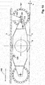
- FIG. 9 the support roller elements 6 ', 7' are seen in a side view, and in FIG. 10 in a view of the underside of the vehicle.
- FIG. 11 shows that the support roller element 7 'as well as the support roller element 7 of the first vehicle version by means of a trapezoidal rocker is attached to the frame 3.
- FIG. 12 shows in enlarged form the connection of the supporting rolling element 7 'with the frame, wherein the trapezoidal rocker is covered by a panel.
- the suspension of the supporting rolling element 7 'on the frame is designed as well as the suspension of the supporting rolling element 7 to the frame 3 according to the FIG. 6 ,
- the inventive design of the vehicle makes it possible to store the largest possible proportion of the total weight of the vehicle on the supporting rolling elements 4, 5, while a small proportion of the weight on the support roller element 6, 6 'can store.
- the further supporting rolling element 7, 7 'can be designed and arranged such that in the rest position it absorbs practically no portion of the weight of the vehicle and / or the load and is pressed against the roadway surface only by means of the trapezoidal rocker.
- FIG. 13 shows a representation in which the leverage ratios of the mutually movable parts are made clear schematically.
- the vehicle in the FIGS. 13 and 14 is shown, has two supporting rolling elements 4, 5 in the form of individually driven wheels, whose bearings are connected by an imaginary connecting line 108.
- the center of gravity of the vehicle is ideally above the connecting line 108.
- Connecting line 108 are two supporting rolling elements 6 ", 6 '" in the form of wheels whose rotary bearings are fixedly connected to the frame 3.
- the connecting legs 112, 113 are articulated in a respective pivot bearing 100 to the frame and pivotable in a vertical plane. At the connecting legs 112, 113, the rotation bearing devices 101 of the wheels 107, 107 'are fixed. Along the connecting legs 112, 113 101 supporting elements 105 are supported between the pivot bearings 100 and the rotation bearing devices, which are connected to the load receiving device 2. On the support elements 105 opposite side of the connecting line 108 further, connected to the load-receiving device supporting elements 104 are supported directly on the frame 3.
- Each of the rollers 6 ", 6 '", 107, 107' can be replaced by another support roller element, for example a ball rotatable in a rotation bearing device, wherein the attachment or articulation of the support roller elements to the frame 3 remains unchanged.
- FIG. 14 are the support points at which the load-bearing device 2 is supported by means of the support members 104, 105 on the frame 3, indicated by the arrows 110, 111, 115, 116.
- FIG. 15 a vehicle is shown with a frame 3 and a load-bearing device 2 in the form of a loading surface 2, which is supported on the pivot joint 120 on the frame and by means of the support member 105 on the connecting leg 112.
- the connecting leg is pivotally mounted on the pivot joint 100.
- the wheel 107 is rotatably mounted on the connecting leg 112.
- the support member 105 is movably supported on the connecting leg 112 in the middle between the bearing of the wheel 107 and the pivot joint 100.
- the compensated by the pivotable wheel 107 height difference in the road surface 106 is designated by "x".
- FIG. 16 shows a vehicle with a load receiving device 2, which is supported on a frame 3.
- the supporting rolling elements 4, 5 are designed as wheels with a common drive axle, but separate drive motors.
- the front in the direction of travel 109 supporting rolling elements are mounted as rotatably mounted roller balls 121, 122 directly to the frame 3.
- the supporting rolling elements 123, 124 are mounted as rolling balls on the connecting lever 112 '. This is articulated in the pivot joint 100 'on the frame 3.
- the support member 105' is supported, which carries the load bearing 2.
- the support member 105 'and the connecting lever 112' are bow-shaped semicircular formed as bent sheets, and all articulation and support points are provided for each of the support rollers 123, 124 double.
- FIG. 17 shows a vehicle in which a lifting device is provided for lifting the load receiving device.
- the lifting of the load-receiving device takes place by pivoting the arm on which the support roller element is arranged, in the sense of the double arrow.
- FIG. 18 shows a raised position of the load receiving device after the arm on which the support roller member is mounted, has been pivoted to the axis of the support rollers. This can be z. B. by a traction drive, such as the winding of a pull rope, done.
Applications Claiming Priority (1)
| Application Number | Priority Date | Filing Date | Title |
|---|---|---|---|
| DE102017207748.4A DE102017207748A1 (de) | 2017-05-08 | 2017-05-08 | Fahrzeug zur Aufnahme von Lasten |
Publications (2)
| Publication Number | Publication Date |
|---|---|
| EP3401119A1 true EP3401119A1 (fr) | 2018-11-14 |
| EP3401119B1 EP3401119B1 (fr) | 2020-08-05 |
Family
ID=62148121
Family Applications (1)
| Application Number | Title | Priority Date | Filing Date |
|---|---|---|---|
| EP18171038.5A Active EP3401119B1 (fr) | 2017-05-08 | 2018-05-07 | Véhicule de chargement des charges |
Country Status (3)
| Country | Link |
|---|---|
| EP (1) | EP3401119B1 (fr) |
| DE (1) | DE102017207748A1 (fr) |
| ES (1) | ES2823156T3 (fr) |
Families Citing this family (1)
| Publication number | Priority date | Publication date | Assignee | Title |
|---|---|---|---|---|
| CN109676622B (zh) * | 2019-01-17 | 2021-04-09 | 商丘师范学院 | 社区矫正机器人 |
Citations (5)
| Publication number | Priority date | Publication date | Assignee | Title |
|---|---|---|---|---|
| US4359116A (en) * | 1980-01-21 | 1982-11-16 | Standard Manufacturing Company, Incorporated | Ground pressure reducing undercarriage unit |
| US4515235A (en) * | 1982-05-25 | 1985-05-07 | Shinko Electric Co., Ltd. | Driverless guided vehicle |
| JPH0492786A (ja) * | 1990-08-09 | 1992-03-25 | Nissan Motor Co Ltd | 無人台車の走行装置 |
| WO2002046031A1 (fr) * | 2000-12-04 | 2002-06-13 | Allard Eric J | Vehicule de transport multidirectionnel telecommande |
| DE102007002242A1 (de) * | 2007-01-10 | 2008-07-17 | Sew-Eurodrive Gmbh & Co. Kg | System, insbesondere fahrerloses Transportfahrzeug |
Family Cites Families (3)
| Publication number | Priority date | Publication date | Assignee | Title |
|---|---|---|---|---|
| EP0740542B1 (fr) * | 1994-11-18 | 2005-02-02 | Degonda-Rehab S.A. | Siege roulant pour le transport ou l'assistance au deplacement d'au moins un utilisateur, notamment d'une personne handicapee |
| JP4681016B2 (ja) * | 2008-03-10 | 2011-05-11 | 株式会社豊田中央研究所 | 倒立振子型車輪移動体 |
| DE202016106329U1 (de) * | 2016-11-11 | 2016-12-15 | Mk-Lietz Maschinen & Apparatebau | Transportwagen |
-
2017
- 2017-05-08 DE DE102017207748.4A patent/DE102017207748A1/de not_active Ceased
-
2018
- 2018-05-07 EP EP18171038.5A patent/EP3401119B1/fr active Active
- 2018-05-07 ES ES18171038T patent/ES2823156T3/es active Active
Patent Citations (5)
| Publication number | Priority date | Publication date | Assignee | Title |
|---|---|---|---|---|
| US4359116A (en) * | 1980-01-21 | 1982-11-16 | Standard Manufacturing Company, Incorporated | Ground pressure reducing undercarriage unit |
| US4515235A (en) * | 1982-05-25 | 1985-05-07 | Shinko Electric Co., Ltd. | Driverless guided vehicle |
| JPH0492786A (ja) * | 1990-08-09 | 1992-03-25 | Nissan Motor Co Ltd | 無人台車の走行装置 |
| WO2002046031A1 (fr) * | 2000-12-04 | 2002-06-13 | Allard Eric J | Vehicule de transport multidirectionnel telecommande |
| DE102007002242A1 (de) * | 2007-01-10 | 2008-07-17 | Sew-Eurodrive Gmbh & Co. Kg | System, insbesondere fahrerloses Transportfahrzeug |
Also Published As
| Publication number | Publication date |
|---|---|
| ES2823156T3 (es) | 2021-05-06 |
| DE102017207748A1 (de) | 2018-11-08 |
| EP3401119B1 (fr) | 2020-08-05 |
Similar Documents
| Publication | Publication Date | Title |
|---|---|---|
| WO2018137981A1 (fr) | Chariot de manutention motorisé amélioré | |
| DE60215316T2 (de) | Freifliegender antrieb für fahrzeug | |
| DE102010017709A1 (de) | Transportwagen | |
| WO2011154533A1 (fr) | Mécanisme de roulement à courroie et essieu de mécanisme de roulement présentant des mécanismes de roulement à courroie | |
| DE102018107226A1 (de) | Transportwagen | |
| EP3426593B1 (fr) | Véhicule de transport sans conducteur | |
| DE202016008844U1 (de) | "AFW"-Fahrzeugaufhängung (Varianten) | |
| DE102006042119A1 (de) | Lastenroller | |
| EP3296249A1 (fr) | Machine de travail articulée | |
| DE2263568C2 (de) | Förderanlage mit Transportbehältern | |
| DE10309621A1 (de) | Motorgetriebenes, handgeführtes Transportfahrzeug mit intuitiver Haltegriffsteuerung | |
| EP3401119B1 (fr) | Véhicule de chargement des charges | |
| DE3049198C2 (fr) | ||
| EP0678443B1 (fr) | Train de roulement, notamment pour machines de travail mobiles et véhicules | |
| DE202006020569U1 (de) | Stabilitätssystem für ein Industriefahrzeug | |
| DE202016106329U1 (de) | Transportwagen | |
| EP3689709A1 (fr) | Plateforme de conduite | |
| EP2660130A1 (fr) | Véhicule à deux voies doté de chenilles | |
| DE4342944A1 (de) | Flurförderzeug | |
| DE10354548B4 (de) | Fahrzeug für den Einsatz in unwegsamem Gelände | |
| DE102013000724B4 (de) | Geländegängiger Rollstuhl | |
| DE60010595T2 (de) | Untergestell für Fahrzeug und Rollstuhl ausgestattet mit solchen Untergestell | |
| DE102019109936A1 (de) | Frontgetriebenes Fahrzeug, insbesondere in Art eines Scooters | |
| DE19626119A1 (de) | Rangierwagenheber | |
| DE2437476A1 (de) | Gelaendegaengiges fahrzeug |
Legal Events
| Date | Code | Title | Description |
|---|---|---|---|
| PUAI | Public reference made under article 153(3) epc to a published international application that has entered the european phase |
Free format text: ORIGINAL CODE: 0009012 |
|
| STAA | Information on the status of an ep patent application or granted ep patent |
Free format text: STATUS: THE APPLICATION HAS BEEN PUBLISHED |
|
| AK | Designated contracting states |
Kind code of ref document: A1 Designated state(s): AL AT BE BG CH CY CZ DE DK EE ES FI FR GB GR HR HU IE IS IT LI LT LU LV MC MK MT NL NO PL PT RO RS SE SI SK SM TR |
|
| AX | Request for extension of the european patent |
Extension state: BA ME |
|
| STAA | Information on the status of an ep patent application or granted ep patent |
Free format text: STATUS: REQUEST FOR EXAMINATION WAS MADE |
|
| 17P | Request for examination filed |
Effective date: 20190510 |
|
| RBV | Designated contracting states (corrected) |
Designated state(s): AL AT BE BG CH CY CZ DE DK EE ES FI FR GB GR HR HU IE IS IT LI LT LU LV MC MK MT NL NO PL PT RO RS SE SI SK SM TR |
|
| GRAP | Despatch of communication of intention to grant a patent |
Free format text: ORIGINAL CODE: EPIDOSNIGR1 |
|
| STAA | Information on the status of an ep patent application or granted ep patent |
Free format text: STATUS: GRANT OF PATENT IS INTENDED |
|
| RIC1 | Information provided on ipc code assigned before grant |
Ipc: B62D 61/04 20060101ALI20200210BHEP Ipc: B62D 61/10 20060101ALI20200210BHEP Ipc: B60B 19/14 20060101AFI20200210BHEP Ipc: B62D 37/00 20060101ALI20200210BHEP Ipc: B62B 3/06 20060101ALI20200210BHEP Ipc: B60B 33/06 20060101ALI20200210BHEP Ipc: B60B 19/00 20060101ALI20200210BHEP |
|
| INTG | Intention to grant announced |
Effective date: 20200226 |
|
| GRAS | Grant fee paid |
Free format text: ORIGINAL CODE: EPIDOSNIGR3 |
|
| GRAA | (expected) grant |
Free format text: ORIGINAL CODE: 0009210 |
|
| STAA | Information on the status of an ep patent application or granted ep patent |
Free format text: STATUS: THE PATENT HAS BEEN GRANTED |
|
| AK | Designated contracting states |
Kind code of ref document: B1 Designated state(s): AL AT BE BG CH CY CZ DE DK EE ES FI FR GB GR HR HU IE IS IT LI LT LU LV MC MK MT NL NO PL PT RO RS SE SI SK SM TR |
|
| REG | Reference to a national code |
Ref country code: GB Ref legal event code: FG4D Free format text: NOT ENGLISH |
|
| REG | Reference to a national code |
Ref country code: CH Ref legal event code: EP |
|
| REG | Reference to a national code |
Ref country code: AT Ref legal event code: REF Ref document number: 1298198 Country of ref document: AT Kind code of ref document: T Effective date: 20200815 |
|
| REG | Reference to a national code |
Ref country code: DE Ref legal event code: R096 Ref document number: 502018002065 Country of ref document: DE |
|
| REG | Reference to a national code |
Ref country code: IE Ref legal event code: FG4D Free format text: LANGUAGE OF EP DOCUMENT: GERMAN |
|
| REG | Reference to a national code |
Ref country code: NL Ref legal event code: FP |
|
| REG | Reference to a national code |
Ref country code: LT Ref legal event code: MG4D |
|
| PG25 | Lapsed in a contracting state [announced via postgrant information from national office to epo] |
Ref country code: GR Free format text: LAPSE BECAUSE OF FAILURE TO SUBMIT A TRANSLATION OF THE DESCRIPTION OR TO PAY THE FEE WITHIN THE PRESCRIBED TIME-LIMIT Effective date: 20201106 Ref country code: BG Free format text: LAPSE BECAUSE OF FAILURE TO SUBMIT A TRANSLATION OF THE DESCRIPTION OR TO PAY THE FEE WITHIN THE PRESCRIBED TIME-LIMIT Effective date: 20201105 Ref country code: SE Free format text: LAPSE BECAUSE OF FAILURE TO SUBMIT A TRANSLATION OF THE DESCRIPTION OR TO PAY THE FEE WITHIN THE PRESCRIBED TIME-LIMIT Effective date: 20200805 Ref country code: HR Free format text: LAPSE BECAUSE OF FAILURE TO SUBMIT A TRANSLATION OF THE DESCRIPTION OR TO PAY THE FEE WITHIN THE PRESCRIBED TIME-LIMIT Effective date: 20200805 Ref country code: LT Free format text: LAPSE BECAUSE OF FAILURE TO SUBMIT A TRANSLATION OF THE DESCRIPTION OR TO PAY THE FEE WITHIN THE PRESCRIBED TIME-LIMIT Effective date: 20200805 Ref country code: PT Free format text: LAPSE BECAUSE OF FAILURE TO SUBMIT A TRANSLATION OF THE DESCRIPTION OR TO PAY THE FEE WITHIN THE PRESCRIBED TIME-LIMIT Effective date: 20201207 Ref country code: FI Free format text: LAPSE BECAUSE OF FAILURE TO SUBMIT A TRANSLATION OF THE DESCRIPTION OR TO PAY THE FEE WITHIN THE PRESCRIBED TIME-LIMIT Effective date: 20200805 Ref country code: NO Free format text: LAPSE BECAUSE OF FAILURE TO SUBMIT A TRANSLATION OF THE DESCRIPTION OR TO PAY THE FEE WITHIN THE PRESCRIBED TIME-LIMIT Effective date: 20201105 |
|
| PG25 | Lapsed in a contracting state [announced via postgrant information from national office to epo] |
Ref country code: PL Free format text: LAPSE BECAUSE OF FAILURE TO SUBMIT A TRANSLATION OF THE DESCRIPTION OR TO PAY THE FEE WITHIN THE PRESCRIBED TIME-LIMIT Effective date: 20200805 Ref country code: RS Free format text: LAPSE BECAUSE OF FAILURE TO SUBMIT A TRANSLATION OF THE DESCRIPTION OR TO PAY THE FEE WITHIN THE PRESCRIBED TIME-LIMIT Effective date: 20200805 Ref country code: LV Free format text: LAPSE BECAUSE OF FAILURE TO SUBMIT A TRANSLATION OF THE DESCRIPTION OR TO PAY THE FEE WITHIN THE PRESCRIBED TIME-LIMIT Effective date: 20200805 Ref country code: IS Free format text: LAPSE BECAUSE OF FAILURE TO SUBMIT A TRANSLATION OF THE DESCRIPTION OR TO PAY THE FEE WITHIN THE PRESCRIBED TIME-LIMIT Effective date: 20201205 |
|
| PG25 | Lapsed in a contracting state [announced via postgrant information from national office to epo] |
Ref country code: SM Free format text: LAPSE BECAUSE OF FAILURE TO SUBMIT A TRANSLATION OF THE DESCRIPTION OR TO PAY THE FEE WITHIN THE PRESCRIBED TIME-LIMIT Effective date: 20200805 Ref country code: EE Free format text: LAPSE BECAUSE OF FAILURE TO SUBMIT A TRANSLATION OF THE DESCRIPTION OR TO PAY THE FEE WITHIN THE PRESCRIBED TIME-LIMIT Effective date: 20200805 Ref country code: DK Free format text: LAPSE BECAUSE OF FAILURE TO SUBMIT A TRANSLATION OF THE DESCRIPTION OR TO PAY THE FEE WITHIN THE PRESCRIBED TIME-LIMIT Effective date: 20200805 Ref country code: CZ Free format text: LAPSE BECAUSE OF FAILURE TO SUBMIT A TRANSLATION OF THE DESCRIPTION OR TO PAY THE FEE WITHIN THE PRESCRIBED TIME-LIMIT Effective date: 20200805 Ref country code: RO Free format text: LAPSE BECAUSE OF FAILURE TO SUBMIT A TRANSLATION OF THE DESCRIPTION OR TO PAY THE FEE WITHIN THE PRESCRIBED TIME-LIMIT Effective date: 20200805 |
|
| REG | Reference to a national code |
Ref country code: ES Ref legal event code: FG2A Ref document number: 2823156 Country of ref document: ES Kind code of ref document: T3 Effective date: 20210506 |
|
| REG | Reference to a national code |
Ref country code: DE Ref legal event code: R097 Ref document number: 502018002065 Country of ref document: DE |
|
| PG25 | Lapsed in a contracting state [announced via postgrant information from national office to epo] |
Ref country code: AL Free format text: LAPSE BECAUSE OF FAILURE TO SUBMIT A TRANSLATION OF THE DESCRIPTION OR TO PAY THE FEE WITHIN THE PRESCRIBED TIME-LIMIT Effective date: 20200805 |
|
| PLBE | No opposition filed within time limit |
Free format text: ORIGINAL CODE: 0009261 |
|
| STAA | Information on the status of an ep patent application or granted ep patent |
Free format text: STATUS: NO OPPOSITION FILED WITHIN TIME LIMIT |
|
| PG25 | Lapsed in a contracting state [announced via postgrant information from national office to epo] |
Ref country code: SK Free format text: LAPSE BECAUSE OF FAILURE TO SUBMIT A TRANSLATION OF THE DESCRIPTION OR TO PAY THE FEE WITHIN THE PRESCRIBED TIME-LIMIT Effective date: 20200805 |
|
| 26N | No opposition filed |
Effective date: 20210507 |
|
| PG25 | Lapsed in a contracting state [announced via postgrant information from national office to epo] |
Ref country code: SI Free format text: LAPSE BECAUSE OF FAILURE TO SUBMIT A TRANSLATION OF THE DESCRIPTION OR TO PAY THE FEE WITHIN THE PRESCRIBED TIME-LIMIT Effective date: 20200805 |
|
| REG | Reference to a national code |
Ref country code: CH Ref legal event code: PL |
|
| PG25 | Lapsed in a contracting state [announced via postgrant information from national office to epo] |
Ref country code: CH Free format text: LAPSE BECAUSE OF NON-PAYMENT OF DUE FEES Effective date: 20210531 Ref country code: LU Free format text: LAPSE BECAUSE OF NON-PAYMENT OF DUE FEES Effective date: 20210507 Ref country code: MC Free format text: LAPSE BECAUSE OF FAILURE TO SUBMIT A TRANSLATION OF THE DESCRIPTION OR TO PAY THE FEE WITHIN THE PRESCRIBED TIME-LIMIT Effective date: 20200805 Ref country code: LI Free format text: LAPSE BECAUSE OF NON-PAYMENT OF DUE FEES Effective date: 20210531 |
|
| REG | Reference to a national code |
Ref country code: BE Ref legal event code: MM Effective date: 20210531 |
|
| PG25 | Lapsed in a contracting state [announced via postgrant information from national office to epo] |
Ref country code: IE Free format text: LAPSE BECAUSE OF NON-PAYMENT OF DUE FEES Effective date: 20210507 |
|
| PG25 | Lapsed in a contracting state [announced via postgrant information from national office to epo] |
Ref country code: BE Free format text: LAPSE BECAUSE OF NON-PAYMENT OF DUE FEES Effective date: 20210531 |
|
| GBPC | Gb: european patent ceased through non-payment of renewal fee |
Effective date: 20220507 |
|
| PG25 | Lapsed in a contracting state [announced via postgrant information from national office to epo] |
Ref country code: GB Free format text: LAPSE BECAUSE OF NON-PAYMENT OF DUE FEES Effective date: 20220507 |
|
| P01 | Opt-out of the competence of the unified patent court (upc) registered |
Effective date: 20230524 |
|
| PG25 | Lapsed in a contracting state [announced via postgrant information from national office to epo] |
Ref country code: CY Free format text: LAPSE BECAUSE OF FAILURE TO SUBMIT A TRANSLATION OF THE DESCRIPTION OR TO PAY THE FEE WITHIN THE PRESCRIBED TIME-LIMIT Effective date: 20200805 |
|
| PG25 | Lapsed in a contracting state [announced via postgrant information from national office to epo] |
Ref country code: HU Free format text: LAPSE BECAUSE OF FAILURE TO SUBMIT A TRANSLATION OF THE DESCRIPTION OR TO PAY THE FEE WITHIN THE PRESCRIBED TIME-LIMIT; INVALID AB INITIO Effective date: 20180507 |
|
| PGFP | Annual fee paid to national office [announced via postgrant information from national office to epo] |
Ref country code: NL Payment date: 20230519 Year of fee payment: 6 Ref country code: IT Payment date: 20230531 Year of fee payment: 6 Ref country code: FR Payment date: 20230517 Year of fee payment: 6 Ref country code: ES Payment date: 20230621 Year of fee payment: 6 Ref country code: DE Payment date: 20230519 Year of fee payment: 6 |
|
| PG25 | Lapsed in a contracting state [announced via postgrant information from national office to epo] |
Ref country code: MK Free format text: LAPSE BECAUSE OF FAILURE TO SUBMIT A TRANSLATION OF THE DESCRIPTION OR TO PAY THE FEE WITHIN THE PRESCRIBED TIME-LIMIT Effective date: 20200805 |