EP3689709A1 - Plateforme de conduite - Google Patents
Plateforme de conduite Download PDFInfo
- Publication number
- EP3689709A1 EP3689709A1 EP20000018.0A EP20000018A EP3689709A1 EP 3689709 A1 EP3689709 A1 EP 3689709A1 EP 20000018 A EP20000018 A EP 20000018A EP 3689709 A1 EP3689709 A1 EP 3689709A1
- Authority
- EP
- European Patent Office
- Prior art keywords
- wheel
- bogie
- drive
- units
- driving platform
- Prior art date
- Legal status (The legal status is an assumption and is not a legal conclusion. Google has not performed a legal analysis and makes no representation as to the accuracy of the status listed.)
- Withdrawn
Links
Images


Classifications
-
- B—PERFORMING OPERATIONS; TRANSPORTING
- B62—LAND VEHICLES FOR TRAVELLING OTHERWISE THAN ON RAILS
- B62D—MOTOR VEHICLES; TRAILERS
- B62D7/00—Steering linkage; Stub axles or their mountings
- B62D7/06—Steering linkage; Stub axles or their mountings for individually-pivoted wheels, e.g. on king-pins
- B62D7/14—Steering linkage; Stub axles or their mountings for individually-pivoted wheels, e.g. on king-pins the pivotal axes being situated in more than one plane transverse to the longitudinal centre line of the vehicle, e.g. all-wheel steering
- B62D7/15—Steering linkage; Stub axles or their mountings for individually-pivoted wheels, e.g. on king-pins the pivotal axes being situated in more than one plane transverse to the longitudinal centre line of the vehicle, e.g. all-wheel steering characterised by means varying the ratio between the steering angles of the steered wheels
- B62D7/1509—Steering linkage; Stub axles or their mountings for individually-pivoted wheels, e.g. on king-pins the pivotal axes being situated in more than one plane transverse to the longitudinal centre line of the vehicle, e.g. all-wheel steering characterised by means varying the ratio between the steering angles of the steered wheels with different steering modes, e.g. crab-steering, or steering specially adapted for reversing of the vehicle
-
- B—PERFORMING OPERATIONS; TRANSPORTING
- B62—LAND VEHICLES FOR TRAVELLING OTHERWISE THAN ON RAILS
- B62D—MOTOR VEHICLES; TRAILERS
- B62D61/00—Motor vehicles or trailers, characterised by the arrangement or number of wheels, not otherwise provided for, e.g. four wheels in diamond pattern
- B62D61/10—Motor vehicles or trailers, characterised by the arrangement or number of wheels, not otherwise provided for, e.g. four wheels in diamond pattern with more than four wheels
-
- B—PERFORMING OPERATIONS; TRANSPORTING
- B62—LAND VEHICLES FOR TRAVELLING OTHERWISE THAN ON RAILS
- B62D—MOTOR VEHICLES; TRAILERS
- B62D63/00—Motor vehicles or trailers not otherwise provided for
- B62D63/02—Motor vehicles
-
- B—PERFORMING OPERATIONS; TRANSPORTING
- B62—LAND VEHICLES FOR TRAVELLING OTHERWISE THAN ON RAILS
- B62D—MOTOR VEHICLES; TRAILERS
- B62D7/00—Steering linkage; Stub axles or their mountings
- B62D7/02—Steering linkage; Stub axles or their mountings for pivoted bogies
- B62D7/026—Steering linkage; Stub axles or their mountings for pivoted bogies characterised by comprising more than one bogie, e.g. situated in more than one plane transversal to the longitudinal centre line of the vehicle
-
- B—PERFORMING OPERATIONS; TRANSPORTING
- B62—LAND VEHICLES FOR TRAVELLING OTHERWISE THAN ON RAILS
- B62D—MOTOR VEHICLES; TRAILERS
- B62D11/00—Steering non-deflectable wheels; Steering endless tracks or the like
- B62D11/02—Steering non-deflectable wheels; Steering endless tracks or the like by differentially driving ground-engaging elements on opposite vehicle sides
- B62D11/04—Steering non-deflectable wheels; Steering endless tracks or the like by differentially driving ground-engaging elements on opposite vehicle sides by means of separate power sources
-
- B—PERFORMING OPERATIONS; TRANSPORTING
- B62—LAND VEHICLES FOR TRAVELLING OTHERWISE THAN ON RAILS
- B62D—MOTOR VEHICLES; TRAILERS
- B62D11/00—Steering non-deflectable wheels; Steering endless tracks or the like
- B62D11/20—Endless-track steering having pivoted bogie carrying track
Definitions
- the invention relates to a steered driving platform.
- the invention relates to a driving platform with a twin-wheel steering device for an all-wheel drive electric vehicle.
- a swivel axle steering system which is known in particular as a turntable steering system
- an entire axle including the two wheels arranged at its ends is pivoted about an axis of rotation.
- axle steering each wheel is guided by an axle stub and swiveled around a separate axis of rotation.
- the rotation about the axis of rotation is effected by means of a steering force, which is usually provided by a steering gear.
- the object of the invention is to show a driving platform which has good maneuverability in a small space, enables fast steering, takes up little space and is inexpensive to manufacture.
- the driving platform has a chassis, a plurality of double wheel units and a control unit.
- the chassis can be designed differently depending on the application.
- the double wheel units are arranged on the chassis.
- Each of the dual wheel units has a bogie, a first and a second wheel and a drive unit.
- the bogie is rotatably mounted about a vertical axis relative to a bogie.
- the bogie can preferably be designed as a turntable; however, it can also be designed in other designs.
- the bogie is rotatably mounted in a bogie bearing. In a particularly simple construction of the bogie bearing, a cylindrical bolt of the bogie is inserted into a hollow cylindrical opening of the bogie or vice versa. This enables the bogie to rotate about the vertical axis.
- the bogie is passively rotatable.
- the bogie is preferably designed to be shock-absorbent by means of a spring element.
- the first and the second wheel are rotatably mounted on the bogie about a common horizontal axis by means of a wheel holder.
- the wheel holder is designed so that the two wheels are preferably arranged in close proximity and with a parallel running direction.
- the wheel mounts can also be structurally connected.
- the wheel mounts can have a common axle body or two partial axles.
- the wheel holders are designed in such a way that they enable the wheels to rotate about the common horizontal axis.
- the simplest design of the bogie consists of a wheel fork, which holds the wheel mounts of the two wheels.
- the structural design can also take place in other types of axles and wheel receptacles which have the features described.
- the two wheels are independently rotatable in the wheel holder.
- the drive unit has a first wheel drive, a second wheel drive and a control unit.
- the first wheel drive is assigned to the first wheel and the second wheel drive to the second wheel, the wheel drives are preferably realized by an electric motor.
- each wheel drive is implemented, for example, by a hub motor.
- the small space requirement and efficient power transmission by a direct drive are particularly advantageous here.
- the wheel drive and the impeller are arranged at a distance from one another. The power is then transmitted via a gearbox. This design makes it possible, for example, to use a common motor for both wheel drives and to assign the torque transmission to the two wheels by means of a suitable gear.
- each of the two wheel drives is designed to separately apply a torque to the respectively assigned impeller.
- the speed of rotation of each impeller is set individually using the separate torque application.
- a large number of different operating states can thus be set in relation to the ratio of the rotary movements of the two impellers to one another.
- the torque can be applied both as a drive and as a brake.
- the control unit is connected to both wheel drives in such a way that a control signal can be transmitted. It is designed to implement the driving commands from the driver, the vehicle itself or another source by adapting the control signal.
- the control unit is designed to transmit a control signal to the wheel drives.
- the control signal can be transmitted separately to one wheel drive or to both drives together.
- the control signal brakes or accelerates each of the wheel drives individually and consequently causes a steering movement or straight travel movement of the bogie and thus of the vehicle.
- the control unit can be structurally connected to the bogie, but can also be arranged at another location, for example on a chassis.
- control units of the dual wheel units present in a plurality according to the invention are designed to control the dual wheel units in a coordinated manner.
- the control units can be interconnected, for example, via a data bus. It is also possible to design the control units as a uniform central control circuit. It is also possible to arrange the control units on the dual wheel units and to connect them in a star shape to a central control circuit. In any case, the control units are directly or indirectly data-connected to one another.
- control unit is able to detect the relative alignment of the bogie of the dual wheel unit.
- the control units of the dual wheel units are able to actuate the wheel drives of each double wheel unit independently of the wheel drives of the other double wheel units.
- these are designed to coordinate and drive all dual wheel units in a coordinated manner for a resulting driving movement.
- rectilinear movements can take place in any direction without changing the orientation of the driving platform per se, or rotational movements of the driving platform in any radius around imaginary points in the plane of movement be performed.
- Compound movements consisting of rotational and translational movement components are also possible.
- rotating around an imaginary point it can be outside or inside the surface of the chassis. For example, to go around a curve, the imaginary point is placed in the vertex of the curve.
- the imaginary point is placed by the control unit in the central vertical axis of the chassis. If the control unit now aligns all dual wheel units by actuating the two wheel drives differently so that their horizontal axes lie on the respective connecting line between the imaginary point and the vertical pivot point of the dual wheel unit, rotation occurs around the imaginary point when the wheels of the dual wheel units are driven.
- the speed of the impellers is in relation to the distance to the imaginary point, the speed increasing with greater distance.
- each dual wheel unit has its own interface, which is able to communicate with the control units of the other dual wheel units in order to coordinate a common travel movement. Communication can be wired or wireless.
- This design has the advantage over a single common central control circuit that each dual wheel unit forms a complete module. Such dual wheel modules can be mass-produced inexpensively. These dual wheel modules can be used to mobilize individual chassis with minimal effort. A single control unit can be more advantageous in the series production of finished travel platforms, since costs for several control units are avoided.
- the bogie is designed to rotate about the vertical axis relative to the bogie by means of a different rotational speed of the running wheels. Due to the parallel arrangement of the impellers, a torque about the axis of rotation of the impellers is caused by a different rotational speed. The torque is transferred from the impellers to the Transfer bogie and causes a torque about the vertical axis and causes rotation of the bogie about the vertical axis. The torque that rotates the bogie is thus generated between the bogie and the road, and not between the bogie and the bogie.
- the vertical axis is preferably arranged centrally between the two impellers. This enables steering operations in the smallest of spaces. A steering movement by counter-rotating wheels is also possible.
- the driving platform When operated as intended, the driving platform according to the invention enables the steering and driving movements described below.
- a different rotational speed of the wheels causes the bogie to rotate about the vertical axis.
- the bogie rotates in the direction of the slower rotating impeller.
- the horizontal axis of the impellers thus changes their position and the impellers corner.
- the rotation of the bogie of one or more double wheel units opposite the chassis is used to steer the driving platform. If the wheels turn at the same speed, the rotation of the bogie is stopped and the cornering is ended.
- the impellers once again drive straight ahead, the direction of the straight-ahead drive now existing deviating from that of the original straight-ahead drive as a result of the intermediate cornering.
- the cornering can be better controlled on the one hand by different rotational speeds of the impellers and on the other hand by different orientations of the bogies.
- the rotational alignment of the chassis can be kept constant during a journey or can be optimally adapted to the available space. This can be particularly advantageous in internal transport when entering narrow paths between rows of shelves.
- Reversing the direction of rotation of an impeller with respect to the direction of rotation of the other impeller enables the bogie to be rotated in the smallest space, preferably without changing the position of the vertical axis. The bogie then turns on the spot.
- Another advantage is that steering can be carried out when the vehicle is stationary. Furthermore, it is possible as an advantage to perform the steering movement particularly quickly, especially when stationary. It is also advantageous that the bogie perform a full circle rotation and any angular position can take opposite the chassis. This goes hand in hand with the fact that the rotation in both directions can also be continued for any angle of more than 360 degrees, and therefore, in particular when parking maneuvers for a change between a steering direction from left to right or vice versa, no previous return to a predetermined neutral position is required. In addition, if the wheel drives are designed appropriately, it is also possible, for example, to drive forwards even when the bogie is positioned rotated by 180 degrees by operating the impellers in the opposite direction of rotation.
- the driving platform according to the invention shows an all-wheel drive vehicle with all the associated advantages without additional measures.
- the drive units of the dual wheel units are designed as electric motors.
- the advantage of using electric motors is their good controllability and high efficiency.
- the control unit can be connected directly to the two wheel drives of a double wheel unit and then controls, for example, the operating current in relation to the applied voltage, the current strength, the direction of flow and the switching state by means of a control signal.
- the torque is directly dependent on the parameters of the operating current, which enables simple control.
- An electric motor wheel drive can be operated with a suitable design by simply switching the current flow in both directions.
- recuperation that is to say to design the electromotive drive unit in such a way that energy can be recovered during a braking operation in a reverse operation.
- the braking system can be partially or completely implemented with the drive unit.
- it can also be practically wear-free working brake device are provided, which also does not cause fine dust emissions caused by abrasion.
- the drive unit is preferably realized by using a hub motor for the first and the second wheel drive.
- the driving platform has at least three double wheel units. From a number of at least three double wheel units, the vertical axes of which are then arranged in a triangle, the driving platform automatically (with every orientation of the double wheel units) has a stable position and stable driving operation is readily possible.
- the driving platform has only two double wheel units, the control units being designed to prevent a position of the two double wheel units in which a respective axis of rotation of the wheels of both double wheel units are arranged on a straight line.
- a stable position of the driving platform is not possible since the driving platform can be tilted about the axis of rotation.
- the control units are designed so that they make this wheel position electronically impossible and are replaced by stable wheel positions and driving maneuvers. For example, a movement transverse to the alignment of the chassis can be replaced by a movement in the longitudinal direction of the chassis and a rotation about the vertical axis of the driving platform.
- the control units are able to replace the actual lateral movement with movement commands, which can also be variably adapted to the available space if a first maneuver does not lead to the desired end position.
- the wheels of one or both double wheel units are preferably at a relatively large distance in order to counteract a tilting of the driving platform.
- the distance between the running wheels is preferably at least half the width of the driving platform.
- the possible applications for the driving platform are very far-reaching, since various superstructures can be arranged on the top of the chassis.
- the driving platform can be trained, for example, for the transportation of people.
- the person to be transported is preferably seated in a passenger body, which is designed as a cabin, and is thus secured against the weather.
- the driving platform then transports the person manually or autonomously to the desired destination.
- the driving platform can preferably be designed in the dimensions of a Euro pallet in the dimensions of 1200 mm x 800 mm.
- the driving platform as the basis for a wheelchair for disabled people.
- the drive unit is designed to drive the wheels of a double wheel unit in the opposite direction to one another.
- the drive unit either has two electric motors which can be operated independently of one another in opposite directions and form the wheel drives, or it has at least one additional gear.
- Such a transmission allows the direction of rotation to be reversed by switching an arrangement of, for example, gear wheels.
- the advantage here is the ability to perform steering movements in the smallest of spaces.
- At least one dual wheel unit has a position sensor which is designed to detect an angular position of the bogie relative to the chassis.
- the position sensor is data-connected to the control unit and is also designed to provide information about the detected one Angular position, hereinafter referred to as angular position data, to be transmitted to the control unit.
- the control unit thus has the information about the angular position of the bogie relative to the chassis.
- the control unit thus knows whether straight-ahead driving or cornering is taking place.
- the radius of cornering is also known.
- the control unit can thus use the travel commands entered, for example a driver, to calculate the rotational speeds at which each of the two wheels must be rotated in order to carry out the desired steering and travel movement of the vehicle corresponding to the travel command.
- all dual-wheel units preferably have a position sensor, so that the position of the bogies of all double-wheel units with respect to one another can be precisely detected and evaluated.
- a distance between the wheels, measured from the center of their contact surfaces on a roadway does not exceed the diameter of the wheels.
- Another advantage of the invention results from the possible spatial proximity of the two impellers.
- the two wheels are thus arranged like twin wheels and can be regarded as a single wheel according to certain regulations.
- the distance between the wheels, measured from the center of their contact surfaces on a roadway particularly preferably does not exceed 460 mm.
- a vehicle with a driving platform according to the invention as a three-wheeled vehicle in the sense of certain regulations, in that two further actively driven dual wheel units are arranged on the chassis.
- a damping element is assigned to the bogie bearing at least one double wheel unit.
- the damping element is designed to dampen a rotational movement of the bogie about the vertical axis.
- the damping element prevents the bogie from suddenly turning around the vertical axis.
- the damping element counteracts any fluttering of the bogie.
- the damping element can be designed to be passive and opposes high angular velocities to a rotational movement of the bogie in the bogie bearing with a high resistance. Furthermore, the damping element can also be designed to be active, in that, for example on the basis of angular position data that a position sensor has recorded, the control unit detects sudden angular position changes that do not correspond to the angular positions that are compatible with the control commands of the control unit to the wheel drives. In this way, a command is issued by means of the control unit and the command activates a damping element which counteracts a further sudden change in the angular position.
- Figure 1 shows a functional representation of an embodiment in a view of the underside of the driving platform.
- a steering process of the driving platform is shown.
- the starting position before the steering process is shown in partial illustration a) and the final position after the steering operation is shown in partial illustration b).
- a dual wheel unit 13 is described below by way of example.
- the other double wheel units function in the same way.
- the bogie 1 of the respective double wheel unit (13) is connected here to the chassis 5 and the wheel holder 6.
- the chassis itself is not part of the device according to the invention.
- the bogie is designed as a wheel fork on a plate.
- the lower end of the wheel fork is connected to the wheel holder 6 and the plate is connected to the chassis 5.
- the connection between the cylindrical plate of the bogie 1 and the hollow cylindrical opening of the bogie 5 is movable and enables the bogie 1 to rotate about the vertical axis 11.
- the first 2 and second impeller 3 are mounted on a common horizontal axis 7 independently of one another and accommodated in the wheel receptacle 6.
- the drive unit 4 consists of the first 8 and the second wheel drive 9 and the control unit 10.
- the first wheel drive 8 is assigned to the first wheel 2 and the second wheel drive 9 is assigned to the second wheel 3.
- both impellers 2, 3 can be acted upon with a torque 12 independently of one another.
- the arrows indicate the direction of action of the torque 12 in the starting position (left).
- a steering movement is generated by the torques in that the bogie rotates about the vertical axis 11 into the end position (right).
- the control unit 10 is connected to the two wheel drives 8, 9 and regulates the engine control by means of a transmitted control signal. In this illustration, the control unit 10 generates control signals for two opposite torques 12.
- Part c) shows the electronically prevented position of the dual wheel units 13.1, 13.2.
- the cross is not part of the device but indicates that it is an impermissible position of the dual wheel units 13.1, 13.2.
- the control unit 10 is designed in such a way that it prevents this double wheel unit position from occurring and is replaced by alternative dual wheel unit positions during driving, by means of which the target position is reached by means of other movements.
- the control unit 10 is arranged in two decentralized units on the double wheel units 13.1, 13.2 and data-connected via a bus system, represented by a dashed line.
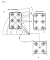
- FIG 2 A driving platform with a centrally formed control unit 10 and three dual wheel units 13 is shown. By using three double wheel units 13 arranged in a triangle, the driving platform stands and drives stably in any wheel position.
- the structure of the dual wheel units 13.1, 13.2, 13.3 differs from Figure 1 only in the structurally outsourced and centrally located control unit 10. This is connected to all wheel drives 8, 9 and thus controls all dual wheel units 13.
- Figure 3 shows a representation of cornering around a pivot point (partial illustration a)), a steering movement by 45 ° (partial illustration b)) and rotation about a pivot point (partial illustration c).
- the pivot point corresponds to the apex of the curve (partial illustration a)).
- the fulcrum is arranged in the center of the chassis 5 (partial illustration c)).
- the control unit aligns all dual wheel units 13 as shown by means of the wheel drives, so that their respective horizontal axes 7 lie on the connecting line between the pivot point and the vertical pivot point of the respective dual wheel unit. If the dual wheel units are driven by their wheels, the driving platform rotates around the pivot point.
- a parallel rotation of the double wheel units 13 can provide a change in the direction of travel, which is an exclusively translational movement without a rotational movement component.
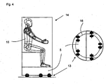
- Figure 4 represents the driving platform in an embodiment for the transport of people.
- a passenger body is placed and fastened on the driving position 5, which is driven by five double wheel units.
- the passenger body 14 encloses the passenger 15 and offers him the opportunity to assume a seated position.
- the chassis 5 is round and the five double wheel units 13 are arranged concentrically on a circular path 16 near the outer edge. This ensures optimal weight distribution and an extremely stable position of the driving platform.
- the driving platform is designed in the manner of an office chair and enables the user to move to different workplaces, for example, within an office.
Landscapes
- Engineering & Computer Science (AREA)
- Chemical & Material Sciences (AREA)
- Combustion & Propulsion (AREA)
- Transportation (AREA)
- Mechanical Engineering (AREA)
- Electric Propulsion And Braking For Vehicles (AREA)
Applications Claiming Priority (1)
| Application Number | Priority Date | Filing Date | Title |
|---|---|---|---|
| DE202019000469.6U DE202019000469U1 (de) | 2019-02-01 | 2019-02-01 | Fahrplattform |
Publications (1)
| Publication Number | Publication Date |
|---|---|
| EP3689709A1 true EP3689709A1 (fr) | 2020-08-05 |
Family
ID=70969954
Family Applications (1)
| Application Number | Title | Priority Date | Filing Date |
|---|---|---|---|
| EP20000018.0A Withdrawn EP3689709A1 (fr) | 2019-02-01 | 2020-01-15 | Plateforme de conduite |
Country Status (2)
| Country | Link |
|---|---|
| EP (1) | EP3689709A1 (fr) |
| DE (1) | DE202019000469U1 (fr) |
Cited By (1)
| Publication number | Priority date | Publication date | Assignee | Title |
|---|---|---|---|---|
| EP4001057A1 (fr) * | 2020-11-18 | 2022-05-25 | Shanghai Quicktron Intelligent Technology Co., Ltd | Procédé de commande pour véhicule, véhicule à guidage automatique et support d'informations lisible par ordinateur |
Families Citing this family (1)
| Publication number | Priority date | Publication date | Assignee | Title |
|---|---|---|---|---|
| DE202021001653U1 (de) | 2021-05-05 | 2022-09-05 | isel-automation GmbH & Co. KG | Lenkvorrichtung |
Citations (5)
| Publication number | Priority date | Publication date | Assignee | Title |
|---|---|---|---|---|
| GB2276854A (en) * | 1993-04-08 | 1994-10-12 | George Robert Kiss | Omnidirectional drive and steering unit. |
| DE102009058213A1 (de) * | 2009-12-15 | 2011-06-16 | Wft Fertigungstechnik Gmbh & Co. Kg | Antriebseinheit für ein Transportsystem sowie Transportsystem mit der Antriebseinheit |
| WO2012048750A1 (fr) * | 2010-10-14 | 2012-04-19 | Wft Fertigungstechnik Gmbh & Co. Kg | Ensemble d'entraînement pour système de transport, et système de transport doté de cet ensemble d'entraînement |
| DE202014000755U1 (de) * | 2014-01-30 | 2015-05-04 | Hit Hafen- Und Industrietechnik Gmbh | Schwerlastniederflurfahrzeug, und System mit einem oder mehreren dieser Fahrzeuge |
| DE102013019726A1 (de) * | 2013-11-27 | 2015-05-28 | Sew-Eurodrive Gmbh & Co Kg | Fahrzeug, insbesondere AGV oder FTS, mit Gestell und zumindest einer Lenkeinheit |
Family Cites Families (6)
| Publication number | Priority date | Publication date | Assignee | Title |
|---|---|---|---|---|
| DE2909667C2 (de) * | 1979-03-12 | 1985-02-14 | Jungheinrich Unternehmensverwaltung Kg, 2000 Hamburg | Elektrischer Antriebs-Steuerteil für lenkbare Fahrzeuge, insbesondere Hublader |
| DE29816515U1 (de) * | 1998-09-15 | 2000-01-27 | Tente Rollen Gmbh & Co | Rollbrett zur Lastenbewegung |
| DE10331773A1 (de) * | 2003-07-11 | 2005-02-10 | Siemens Ag | Lenkbares Trägerfahrzeug |
| DE102009047730A1 (de) * | 2009-12-09 | 2011-06-16 | Zf Friedrichshafen Ag | Lenkbare Antriebsanordnung für ein Flurförderfahrzeug |
| DE102013101561B4 (de) * | 2013-02-15 | 2020-02-13 | Götting KG | Fahrerloses Transportfahrzeug mit einem Sensor |
| DE202015103603U1 (de) * | 2015-07-09 | 2015-08-20 | Christian Gärtner | Transportfahrzeug für das Bewegen von Kameras, Beleuchtungselementen und Dekorations- oder Bühnenbauelementen |
-
2019
- 2019-02-01 DE DE202019000469.6U patent/DE202019000469U1/de active Active
-
2020
- 2020-01-15 EP EP20000018.0A patent/EP3689709A1/fr not_active Withdrawn
Patent Citations (5)
| Publication number | Priority date | Publication date | Assignee | Title |
|---|---|---|---|---|
| GB2276854A (en) * | 1993-04-08 | 1994-10-12 | George Robert Kiss | Omnidirectional drive and steering unit. |
| DE102009058213A1 (de) * | 2009-12-15 | 2011-06-16 | Wft Fertigungstechnik Gmbh & Co. Kg | Antriebseinheit für ein Transportsystem sowie Transportsystem mit der Antriebseinheit |
| WO2012048750A1 (fr) * | 2010-10-14 | 2012-04-19 | Wft Fertigungstechnik Gmbh & Co. Kg | Ensemble d'entraînement pour système de transport, et système de transport doté de cet ensemble d'entraînement |
| DE102013019726A1 (de) * | 2013-11-27 | 2015-05-28 | Sew-Eurodrive Gmbh & Co Kg | Fahrzeug, insbesondere AGV oder FTS, mit Gestell und zumindest einer Lenkeinheit |
| DE202014000755U1 (de) * | 2014-01-30 | 2015-05-04 | Hit Hafen- Und Industrietechnik Gmbh | Schwerlastniederflurfahrzeug, und System mit einem oder mehreren dieser Fahrzeuge |
Cited By (1)
| Publication number | Priority date | Publication date | Assignee | Title |
|---|---|---|---|---|
| EP4001057A1 (fr) * | 2020-11-18 | 2022-05-25 | Shanghai Quicktron Intelligent Technology Co., Ltd | Procédé de commande pour véhicule, véhicule à guidage automatique et support d'informations lisible par ordinateur |
Also Published As
| Publication number | Publication date |
|---|---|
| DE202019000469U1 (de) | 2020-05-15 |
Similar Documents
| Publication | Publication Date | Title |
|---|---|---|
| DE3005169C2 (fr) | ||
| DE112008003171B4 (de) | Fahrzeuglenkvorrichtung | |
| EP2627553B1 (fr) | Ensemble d'entraînement pour système de transport, et système de transport doté de cet ensemble d'entraînement | |
| DE3342355A1 (de) | Fahrzeugaufhaengung | |
| DE202019003072U1 (de) | Fahrplattform und modulare Fahreinheit | |
| DE2922983A1 (de) | Vorrichtung zum stabilisieren eines fahrzeugs | |
| EP3689709A1 (fr) | Plateforme de conduite | |
| DE1455868A1 (de) | Flurfoerderfahrzeug | |
| WO2007031044A1 (fr) | Vehicule destine a des personnes handicapees | |
| DE102017003528B4 (de) | Fahrzeug mit hoher Manövrierbarkeit und vier unabhängig voneinander antreibbaren Antriebsrädern | |
| WO2021190687A1 (fr) | Unité d'entraînement de véhicule et véhicule doté d'une unité d'entraînement de véhicule | |
| EP2560859B1 (fr) | Système mobile | |
| EP3110740B1 (fr) | Chariot de manutention avec essieu d'entraînement différentiel et direction à boggie | |
| EP3653469A1 (fr) | Dispositif de direction d'un véhicule | |
| AT524936B1 (de) | Plattform für mindestens vierrädrige Kraftfahrzeuge mit Elektroantrieb | |
| EP0011881B1 (fr) | Autobus à carrosserie articulée | |
| DE3839107A1 (de) | Lenkrollenanordnung fuer ein dreirad-fahrzeug | |
| DE102004013897B4 (de) | Portalhubstapler mit elektrischer Lenkung | |
| EP3401119B1 (fr) | Véhicule de chargement des charges | |
| DE10144372A1 (de) | Hubwagenfahrwerk | |
| DE102018130969A1 (de) | Antriebsanordnung für ein Fahrzeug und Fahrzeug mit der Antriebsanordnung | |
| WO2018162229A1 (fr) | Système de direction pour un véhicule et procédé de direction d'un véhicule | |
| DE102020123524B4 (de) | Radmodul für ein Kraftfahrzeug | |
| AT525085B1 (de) | Plattform für mindestens vierrädrige Kraftfahrzeuge mit Elektroantrieb | |
| DE102017001060A1 (de) | Modulsystem für Fahrzeuge |
Legal Events
| Date | Code | Title | Description |
|---|---|---|---|
| PUAI | Public reference made under article 153(3) epc to a published international application that has entered the european phase |
Free format text: ORIGINAL CODE: 0009012 |
|
| STAA | Information on the status of an ep patent application or granted ep patent |
Free format text: STATUS: THE APPLICATION HAS BEEN PUBLISHED |
|
| AK | Designated contracting states |
Kind code of ref document: A1 Designated state(s): AL AT BE BG CH CY CZ DE DK EE ES FI FR GB GR HR HU IE IS IT LI LT LU LV MC MK MT NL NO PL PT RO RS SE SI SK SM TR |
|
| AX | Request for extension of the european patent |
Extension state: BA ME |
|
| STAA | Information on the status of an ep patent application or granted ep patent |
Free format text: STATUS: REQUEST FOR EXAMINATION WAS MADE |
|
| 17P | Request for examination filed |
Effective date: 20210205 |
|
| RBV | Designated contracting states (corrected) |
Designated state(s): AL AT BE BG CH CY CZ DE DK EE ES FI FR GB GR HR HU IE IS IT LI LT LU LV MC MK MT NL NO PL PT RO RS SE SI SK SM TR |
|
| STAA | Information on the status of an ep patent application or granted ep patent |
Free format text: STATUS: THE APPLICATION IS DEEMED TO BE WITHDRAWN |
|
| 18D | Application deemed to be withdrawn |
Effective date: 20210206 |