EP0920627B1 - Magnetische trennung mit hilfe von externen und internen gradienten - Google Patents
Magnetische trennung mit hilfe von externen und internen gradienten Download PDFInfo
- Publication number
- EP0920627B1 EP0920627B1 EP97929766A EP97929766A EP0920627B1 EP 0920627 B1 EP0920627 B1 EP 0920627B1 EP 97929766 A EP97929766 A EP 97929766A EP 97929766 A EP97929766 A EP 97929766A EP 0920627 B1 EP0920627 B1 EP 0920627B1
- Authority
- EP
- European Patent Office
- Prior art keywords
- cells
- capture structure
- ferromagnetic
- magnetic
- vessel
- Prior art date
- Legal status (The legal status is an assumption and is not a legal conclusion. Google has not performed a legal analysis and makes no representation as to the accuracy of the status listed.)
- Expired - Lifetime
Links
Images


Classifications
-
- B—PERFORMING OPERATIONS; TRANSPORTING
- B03—SEPARATION OF SOLID MATERIALS USING LIQUIDS OR USING PNEUMATIC TABLES OR JIGS; MAGNETIC OR ELECTROSTATIC SEPARATION OF SOLID MATERIALS FROM SOLID MATERIALS OR FLUIDS; SEPARATION BY HIGH-VOLTAGE ELECTRIC FIELDS
- B03C—MAGNETIC OR ELECTROSTATIC SEPARATION OF SOLID MATERIALS FROM SOLID MATERIALS OR FLUIDS; SEPARATION BY HIGH-VOLTAGE ELECTRIC FIELDS
- B03C1/00—Magnetic separation
- B03C1/02—Magnetic separation acting directly on the substance being separated
- B03C1/025—High gradient magnetic separators
-
- B—PERFORMING OPERATIONS; TRANSPORTING
- B01—PHYSICAL OR CHEMICAL PROCESSES OR APPARATUS IN GENERAL
- B01L—CHEMICAL OR PHYSICAL LABORATORY APPARATUS FOR GENERAL USE
- B01L3/00—Containers or dishes for laboratory use, e.g. laboratory glassware; Droppers
- B01L3/50—Containers for the purpose of retaining a material to be analysed, e.g. test tubes
- B01L3/502—Containers for the purpose of retaining a material to be analysed, e.g. test tubes with fluid transport, e.g. in multi-compartment structures
-
- B—PERFORMING OPERATIONS; TRANSPORTING
- B03—SEPARATION OF SOLID MATERIALS USING LIQUIDS OR USING PNEUMATIC TABLES OR JIGS; MAGNETIC OR ELECTROSTATIC SEPARATION OF SOLID MATERIALS FROM SOLID MATERIALS OR FLUIDS; SEPARATION BY HIGH-VOLTAGE ELECTRIC FIELDS
- B03C—MAGNETIC OR ELECTROSTATIC SEPARATION OF SOLID MATERIALS FROM SOLID MATERIALS OR FLUIDS; SEPARATION BY HIGH-VOLTAGE ELECTRIC FIELDS
- B03C1/00—Magnetic separation
- B03C1/02—Magnetic separation acting directly on the substance being separated
- B03C1/025—High gradient magnetic separators
- B03C1/031—Component parts; Auxiliary operations
- B03C1/033—Component parts; Auxiliary operations characterised by the magnetic circuit
- B03C1/034—Component parts; Auxiliary operations characterised by the magnetic circuit characterised by the matrix elements
-
- B—PERFORMING OPERATIONS; TRANSPORTING
- B03—SEPARATION OF SOLID MATERIALS USING LIQUIDS OR USING PNEUMATIC TABLES OR JIGS; MAGNETIC OR ELECTROSTATIC SEPARATION OF SOLID MATERIALS FROM SOLID MATERIALS OR FLUIDS; SEPARATION BY HIGH-VOLTAGE ELECTRIC FIELDS
- B03C—MAGNETIC OR ELECTROSTATIC SEPARATION OF SOLID MATERIALS FROM SOLID MATERIALS OR FLUIDS; SEPARATION BY HIGH-VOLTAGE ELECTRIC FIELDS
- B03C1/00—Magnetic separation
- B03C1/02—Magnetic separation acting directly on the substance being separated
- B03C1/035—Open gradient magnetic separators, i.e. separators in which the gap is unobstructed, characterised by the configuration of the gap
-
- G—PHYSICS
- G01—MEASURING; TESTING
- G01N—INVESTIGATING OR ANALYSING MATERIALS BY DETERMINING THEIR CHEMICAL OR PHYSICAL PROPERTIES
- G01N27/00—Investigating or analysing materials by the use of electric, electrochemical, or magnetic means
- G01N27/72—Investigating or analysing materials by the use of electric, electrochemical, or magnetic means by investigating magnetic variables
- G01N27/74—Investigating or analysing materials by the use of electric, electrochemical, or magnetic means by investigating magnetic variables of fluids
- G01N27/745—Investigating or analysing materials by the use of electric, electrochemical, or magnetic means by investigating magnetic variables of fluids for detecting magnetic beads used in biochemical assays
-
- G—PHYSICS
- G01—MEASURING; TESTING
- G01N—INVESTIGATING OR ANALYSING MATERIALS BY DETERMINING THEIR CHEMICAL OR PHYSICAL PROPERTIES
- G01N33/00—Investigating or analysing materials by specific methods not covered by groups G01N1/00 - G01N31/00
- G01N33/48—Biological material, e.g. blood, urine; Haemocytometers
- G01N33/50—Chemical analysis of biological material, e.g. blood, urine; Testing involving biospecific ligand binding methods; Immunological testing
- G01N33/53—Immunoassay; Biospecific binding assay; Materials therefor
- G01N33/543—Immunoassay; Biospecific binding assay; Materials therefor with an insoluble carrier for immobilising immunochemicals
- G01N33/54313—Immunoassay; Biospecific binding assay; Materials therefor with an insoluble carrier for immobilising immunochemicals the carrier being characterised by its particulate form
- G01N33/54326—Magnetic particles
-
- G—PHYSICS
- G01—MEASURING; TESTING
- G01N—INVESTIGATING OR ANALYSING MATERIALS BY DETERMINING THEIR CHEMICAL OR PHYSICAL PROPERTIES
- G01N33/00—Investigating or analysing materials by specific methods not covered by groups G01N1/00 - G01N31/00
- G01N33/48—Biological material, e.g. blood, urine; Haemocytometers
- G01N33/50—Chemical analysis of biological material, e.g. blood, urine; Testing involving biospecific ligand binding methods; Immunological testing
- G01N33/53—Immunoassay; Biospecific binding assay; Materials therefor
- G01N33/543—Immunoassay; Biospecific binding assay; Materials therefor with an insoluble carrier for immobilising immunochemicals
- G01N33/54366—Apparatus specially adapted for solid-phase testing
-
- B—PERFORMING OPERATIONS; TRANSPORTING
- B01—PHYSICAL OR CHEMICAL PROCESSES OR APPARATUS IN GENERAL
- B01L—CHEMICAL OR PHYSICAL LABORATORY APPARATUS FOR GENERAL USE
- B01L2400/00—Moving or stopping fluids
- B01L2400/04—Moving fluids with specific forces or mechanical means
- B01L2400/0403—Moving fluids with specific forces or mechanical means specific forces
- B01L2400/043—Moving fluids with specific forces or mechanical means specific forces magnetic forces
-
- Y—GENERAL TAGGING OF NEW TECHNOLOGICAL DEVELOPMENTS; GENERAL TAGGING OF CROSS-SECTIONAL TECHNOLOGIES SPANNING OVER SEVERAL SECTIONS OF THE IPC; TECHNICAL SUBJECTS COVERED BY FORMER USPC CROSS-REFERENCE ART COLLECTIONS [XRACs] AND DIGESTS
- Y10—TECHNICAL SUBJECTS COVERED BY FORMER USPC
- Y10T—TECHNICAL SUBJECTS COVERED BY FORMER US CLASSIFICATION
- Y10T436/00—Chemistry: analytical and immunological testing
- Y10T436/10—Composition for standardization, calibration, simulation, stabilization, preparation or preservation; processes of use in preparation for chemical testing
- Y10T436/108331—Preservative, buffer, anticoagulant or diluent
-
- Y—GENERAL TAGGING OF NEW TECHNOLOGICAL DEVELOPMENTS; GENERAL TAGGING OF CROSS-SECTIONAL TECHNOLOGIES SPANNING OVER SEVERAL SECTIONS OF THE IPC; TECHNICAL SUBJECTS COVERED BY FORMER USPC CROSS-REFERENCE ART COLLECTIONS [XRACs] AND DIGESTS
- Y10—TECHNICAL SUBJECTS COVERED BY FORMER USPC
- Y10T—TECHNICAL SUBJECTS COVERED BY FORMER US CLASSIFICATION
- Y10T436/00—Chemistry: analytical and immunological testing
- Y10T436/25—Chemistry: analytical and immunological testing including sample preparation
- Y10T436/25375—Liberation or purification of sample or separation of material from a sample [e.g., filtering, centrifuging, etc.]
Definitions
- the present invention relates to apparatus and methods for separating, immobilizing, and quantifying biological substances from within a fluid medium. More particularly, the invention relates to conducting observations of biological substances by employing a high internal gradient magnetic capture structure formed within a vessel, in conjunction with an externally-applied force for transporting magnetically responsive material toward the capture structure. The present invention is also useful in conducting quantitative analysis and sample preparation in conjunction with automated cell enumeration techniques.
- Magnetic gradients employed in fluid separations are broadly divided into two categories. Internal magnetic gradients are formed by inducing a magnetization in a susceptible material placed in the interior of a separation vessel. External gradients are formed by an externally positioned magnetic circuit.
- Internal high gradient magnetic separators have been employed for nearly 50 years for removing weakly magnetic materials from slurries such as in the kaolin industry or for removing nanosized magnetic materials from solution.
- a separation vessel is positioned in a uniform magnetic vessel.
- a ferromagnetic structure is positioned within the vessel in order to distort the magnetic field and to generate an "internal" gradient in the field.
- magnetic grade stainless steel wool is packed in a column which is then placed in a uniform magnetic field which induces gradients on the steel wool as in U.S. Patent No. 3,676,337 to Kolm. Gradients as high as 200 kGauss/cm are easily achieved.
- the magnitude of the field gradient in the vicinity of a wire is inversely related to the wire diameter.
- the spatial extent of the high gradient region is proportionally related to the diameter of the wire.
- Table I below indicates the magnitude of a magnetic gradient as a function of distance R, from the center of a ferromagnetic wire for round wires of different diameters.
- the gradients are determined by Maxwell's equations, which produce equations I and II for the strength of the magnetic field about the wires and the gradient of the field.
- the equations give the magnitude of these quantities when the wire has an internal magnetization per unit volume of M. If the wires are composed of "soft" ferromagnetic materials, the magnetization depends on the value, B ext , of an externally applied field. For any value of M, even for a hard ferromagnetic material with constant, uniform magnetization, the dependence on the distance and wire diameter are as shown.
- the apparatus contains a rectangular chamber within a cylinder. One pair of opposing sides of the chamber are made of non-magnetic material, while the other sides are made of magnetic material.
- the flow chamber is packed with a magnetically responsive interstitial separation matrix of steel wool. The material to be separated is run through the chamber, which is positioned in a uniform magnetic field. During separation, the chamber is aligned in the magnetic field such that the magnetic sides of the chamber are parallel to the applied field lines, thus inducing high gradients about the interstitial matrix in the chamber.
- WO 94/11078 discloses a magnetic immobilization device in which magnetically-responsive entities are collected along a ferromagnetic capture structure positioned within the interior of a vessel, such as a suspended wire between the end walls of a chamber, or a wire or metallic wedge situated along a side wall of a chamber.
- magnetic entities are collected along the edge of the collecting wire or wedge in the interior of the chamber.
- External gradient magnetic separators are also known for collecting magnetically responsive particles. External devices are so-named because in such devices, a high gradient magnetic field is produced by a suitable configuration of magnets positioned external to the separation vessel, rather than by an internal magnetic structure.
- a standard bar magnet for example, produces a gradient because the magnetic field lines follow non-linear paths and "fan out" or bulge along respective paths from North to South.
- Typical gradients of about 0.1 to 1.5 kGauss/cm are produced by high quality laboratory magnets.
- These relatively low gradients can be increased by configuring a magnetic circuit to compress or expand the field line density. For example, a second bar magnet positioned in opposition to a first magnet causes repulsion between the two magnets.
- U.S. Patent No. 3,326,374 to Jones and U.S. Patent No. 3,608,718 to Aubrey describe typical external gradient separators. Dipole configured separators for preventing scale and lime build up in water systems are described in U.S. Patent No. 3,228,878 to Moody and U.S. Patent No. 4,946,590 to Herzog. Adjacent magnets of opposing polarity have been used in drum or rotor separators for the separation of ferrous and non-ferrous scrap, as described in U.S. Patent No. 4,869,811 to Wolanski et al. and U.S. Patent No. 4,069,145 to Sommer et al.
- superparamagnetic materials have in the last 20 years become the backbone of magnetic separations technology in a variety of healthcare and bioprocessing applications.
- Such materials ranging in size from 25 nm to 100 ⁇ m, have the property that they are only magnetic when placed in a magnetic field. Once the field is removed, they cease to be magnetic and can be redispersed into suspension.
- the basis for superparamagnetic behavior is that such materials contain magnetic cores smaller than 20-25 nm in diameter, which is estimated to be less than the size of a magnetic domain.
- a magnetic domain is the smallest volume for a permanent magnetic dipole to exist.
- Magnetically responsive particles can be formed about one or more such cores.
- the magnetic material of choice is magnetite, although other transition element oxides and mixtures thereof can be used.
- Magnetic particles of the type described above have been used for various applications, particularly in health care, e.g. immunoassay, cell separation and molecular biology.
- Particles ranging from 2 ⁇ m to 5 ⁇ m are available from Dynal. These particles are composed of spherical polymeric materials into which magnetic crystallites have been deposited. These particles because of their magnetite content and size, are readily separated in relatively low external gradients (0.5 to 2 kGauss/cm).
- Another similar class of materials are particles manufactured by Rhone Poulenc which typically are produced in the 0.75 ⁇ m range. Because of their size, they separate more slowly than the Dynal beads in equivalent gradients.
- Another class of material is available from Advanced Magnetics.
- These particles are basically clusters of magnetite crystals, about 1 ⁇ m in size, which are coated with amino polymer silane to which bioreceptors can be coupled. These highly magnetic materials are easily separated in gradients as low as 0.5 kGauss/cm. Due to their size, both the Advanced Magnetics and Rhone Poulenc materials remain suspended in solution for hours at a time.
- bioanalytical techniques involve identification and separation of target entities such as cells or microbes within a fluid medium such as bodily fluids, culture fluids or samples from the environment. It is also often desirable to maintain the target entity intact and/or viable upon separation in order to analyze, identify, or characterize the target entities. For example, to measure the absolute and relative number of cells in a specific subset of leukocytes in blood, a blood sample is drawn and incubated with a probe, for example a fluorescently labeled antibody specific for this subset. The sample is then diluted with a lysing buffer, optionally including a fixative solution, and the dilute sample is analyzed by flow cytometry. This procedure for analysis can be applied to many different antigens. However, the drawbacks to this procedure become apparent when large samples are required for relatively rare event analyses. In those situations, the time needed for the flow cytometer to analyze these samples becomes extremely long, making the analysis no longer feasible due to economic concerns.
- the current invention seeks to combine some of the benefits provided by the Cytodisk, including multiparameter measurement, indexing, and repeated measurement with new features which allow analysis of intact cells, which can be released for culturing or other re-use, including infusion back into a living organism.
- This invention relates to the immobilization of microscopic entities, including biological entities, such as cells which enables separation of such entities from a fluid medium, including whole blood, into a defined region in a collection chamber, such that analysis by automated means is possible.
- This invention also provides for the quantitative collection of magnetically labeled target entities, such that microliter quantities of sample can be used to detect target entities, including those entities which occur at low frequencies.
- a collection vessel in which ferromagnetic lines are supported by adhesion along a transparent wall.
- the lines have effective diameters of 0.1 ⁇ m to 30 ⁇ m, resulting in immobilization and alignment of magnetically labeled biological materials in an ordered array.
- human blood cells are aligned for automated analysis.
- target material is brought into range of the internal high gradient region by gravity.
- a single applied magnetic field serves dual purposes.
- the applied field comprises a first, external magnetic gradient which moves magnetically responsive particles to a region of a collection vessel.
- the applied field induces magnetization in a ferromagnetic collection structure, thereby adding a second, internal gradient which further acts upon the magnetically responsive particles to move them into defined region of the collection vessel for analysis.
- the vessel may be oriented such that the external gradient acts in opposition to, or in conjunction with, the influence of gravity upon the target material.
- the methods of the invention have utility in the separation of biological entities which include a wide variety of substances of biological origins including cells, both eukaryotic (e.g. leukocytes, erythrocytes, platelets, epithelial cells, mesenchymal cells, or fungi) and prokaryotic (e.g. bacteria, protozoa or mycoplasma), viruses, cell components, such as organelles, vesicles, endosomes, lysosomal packages or nuclei, as well as molecules (e.g. proteins) and macromolecules (e.g. nucleic acids - RNA and DNA).
- eukaryotic e.g. leukocytes, erythrocytes, platelets, epithelial cells, mesenchymal cells, or fungi
- prokaryotic e.g. bacteria, protozoa or mycoplasma
- viruses e.g. bacteria, protozoa or mycoplasma
- cell components such as organelles, ve
- the biological entities of interest may be present in at least samples or specimens of varying origins, including, biological fluids such as whole blood, serum, plasma, bone marrow, sputum, urine, cerebrospinal fluid, amniotic fluid or lavage fluids, as well as tissue homogenates, disaggregated tissue, or cell culture medium. They may also be present in material not having a clinical source, such as sludge, slurries, water (e.g. ground water or streams), food products or other sources.
- the method of the invention also has utility in the separation of various bacteria and parasites from fecal matter, urine, or other sources.
- probe refers to an antibody or other specific binding substance which contains or is adapted to include a detectable label.
- Detectable labels include fluorescent, chemiluminescent and radioactive compounds, as well as compounds which have distinct or recognizable lightscattering or other optical properties. Detectable labels also include those compounds which are only detectable upon binding to the characteristic determinant.
- ferromagnetic capture structure refers to a structure of ferromagnetic material which becomes magnetized in the presence of a magnetic field to attract magnetically responsive particles.
- the capture structure may be provided in the form of wires, thin strips, lithographically formed strips, or electroplated ferromagnetic material supported on or by a wall of a separation vessel.
- the ferromagnetic material may include iron, nickel, cobalt, alloys of the same, alloys of magnetic rare earth elements, or other paramagnetic materials.
- internal gradient refers to a magnetic gradient induced by the capture structure when it is placed in a magnetic field.
- external gradient refers to a magnetic gradient applied solely by a configuration of magnets or pole pieces, external to the separation vessel. Electromagnets can also be used to form magnetic fields useful in the invention.
- determinant is used here in a broad sense to denote that portion of the biological entity involved in and responsible for selective binding to a specific binding substance, the presence of which is required for selective binding to occur.
- characteristic determinant is used herein in reference to cells, for example, to signify an epitope (or group of epitopes) that serve to identify a particular cell type and distinguish it from other cell types.
- Cell-associated determinants include, for example, components of the cell membrane, such as membrane-bound proteins or glycoproteins, including cell surface antigens of either host or viral origin, histocompatibility antigens or membrane receptors.
- specific binding substance refers to any substance that selectively recognizes and interacts with the characteristic determinant on a biological entity of interest, to substantial exclusion of determinants present on biological entities that are not of interest.
- specific binding substances which may be used in affinity binding separations are antibodies, anti-haptens, lectins, peptides, peptide-nucleic acid conjugates, nucleic acids, Protein A, Protein G, concanavalin A, soybean agglutinin, hormones and growth factors.
- antibody includes immunoglobulins, monoclonal or polyclonal antibodies, immunoreactive immunoglobulin fragments, single chain antibodies, and peptides, oligonucleotides or any combination thereof which specifically recognize determinants with specificity similar to traditionally generated antibodies.
- magnetically responsive particles refers to magnetic particles of metallic or organo-metallic composition, optionally coated with polymer, preferably coated with a polymer of biological origin such as BSA.
- the particles may be linked with an antibody or other specific binding substance to allow them to bind to biological entities of interest.
- Appropriate magnetic material is manufactured by Dynal, Rhone Poulenc, Miltenyi Biotec, Cardinal Associates, Bangs Labs, Ferrofluidics, and Immunicon Corp.
- a biological entity-magnetic particle complex optionally bound to a fluorescent label or other detectable label.
- the preferred magnetic particles for use in carrying out this invention are particles that behave as true colloids. Such particles are characterized by their sub-micron particle size, which is generally less than about 200 nanometers (nm), and their stability to gravitational separation from solution for extended periods of time. Such small particles facilitate observation of the target entities via optical microscopy since the particles are significantly smaller than the wavelength range of light.
- Suitable materials are composed of a crystalline core of superparamagnetic material surrounded by molecules which may be physically absorbed or covalently attached to the magnetic core and which confer stabilizing colloidal properties. The size of the colloidal particles is sufficiently small that they do not contain a complete magnetic domain, and their Brownian energy exceeds their magnetic moment.
- colloidal magnetic particles are not readily separable from solution as such even with powerful electromagnets, but instead require a magnetic gradient to be generated within the test medium in which the particles are suspended in order to achieve separation of the discrete particles.
- Magnetic particles having the above-described properties can be prepared as described in U.S. Patent Nos. 4,795,698, 5,512,332 and 5,597,531.
- the vessel 10 comprises a pair of opposed parallel wall members 12 and 14 separated by perpendicular walls 16 defining an interior chamber.
- a ferromagnetic collection structure comprising a plurality of longitudinally extensive members is supported on and by an interior surface of the chamber.
- a nickel mesh 18 is positioned upon the interior surface of the wall 14 and held thereon by an adhesive.
- the mesh 18 is formed by electroplating techniques, so that there are no interwoven or overlapping intersections that would undesirably entrap non-target substances by capillary attraction. Suitable meshes include nickel grids used in electron microscopy and are sold by Polysciences, Inc. of Warrington, Pennsylvania (for example, catalog # 8424N).
- the mesh comprises a plurality of longitudinal members 18a joined to cross members 18b forming a grid for mechanical support. The separation between the longitudinal members 18a should be at least twice the diameter of the particles desired to be collected.
- the height of the longitudinal members 18a should be no greater than the average diameter of the target entities.
- the number of target entities that may be captured in the vessel 10 is equal to twice the total length of the longitudinal members 18a divided by the average diameter of the target particles.
- the ferromagnetic collection structure, and hence the chamber, can thus be sized to permit collection of substantially all of the target entities expected to be present in a sample of test fluid.
- a vessel 10 was constructed having longitudinal members 18a extending 150 mm along a region of the wall 14 measuring 5 mm by 3 mm.
- the longitudinal members 18a were 5 ⁇ m in height, 20 ⁇ m wide, and separated by 63 ⁇ m spaces.
- the supporting members 18b were 48 ⁇ m wide.
- the height of the chamber was 0.13 mm, for a chamber volume of 2 ⁇ l.
- the particle collection capacity was 30,000. Such a collection capacity is sufficient for collecting substantially all leukocytes in the chamber volume.
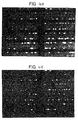
- a test fluid was prepared by adding 0.4 ⁇ g of a 130 nm CD45-labeled ferrofluid, 3 ng of acridine orange, and 10 ng of ethidium bromide to 1 ⁇ l of blood. The test fluid was allowed to incubate for 10 minutes, and deposited in the vessel 10. The vessel was then placed between a pair of magnets 20a and 20b, as shown in FIG. 3, with the mesh 18 positioned at the bottom of the chamber to allow the labeled cells to settle toward the mesh under the influence of gravity, and then to be aligned along the longitudinal members of the mesh in the internally-generated high gradient regions along the longitudinal members. To improve visibility of the captured material, the arrangement shown in FIG. 3 can then be inverted to allow the non-target material to settle away from the mesh 18.
- Acridine orange is absorbed by the nucleated cells, which will emit green light when excited by blue light (460 - 500 nm). Under the same illumination, intracytoplasmatic granules of granulocytes will emit red light. Ethidium bromide is absorbed only by cells having non-intact membranes (i.e. dead cells), and will emit deep red light under blue illumination.
- the optical response of the material in the chamber to blue illumination was viewed through an inverted microscope 22.
- the resulting photographic image of FIG. 4A was obtained under a combination of blue illumination (permitting visibility of the fluorescence emitted from the captured cells) and ambient white illumination (permitting visibility of the ferromagnetic mesh).
- the captured fluorescent cells can easily be distinguished from other blood components.
- Discrimination between cell types can be achieved by detection of selected emission spectra and lightscatter properties of the collected cell. It will be apparent to those skilled in the art that probes with various specificities and different fluorescence excitation and emission can be used to differentiate between the captured, aligned cells. Also, one or more excitation wavelengths can be used to discriminate between the targets, or between the targets and the collection structure. For example, FIG. 4B shows the same collected cells under monochromatic blue fluorescent light. The collection structure is no longer easily visible, and the collected leukocytes are readily discernible. A standard microscope could then be used to observe the cells.
- This example illustrates the differentiation of two types of cells.
- leukocytes were separated from other cell types and among the aligned leukocytes, live cells were discriminated from dead cells by the use of dyes.
- any two (or more) cell types can be differentiated using different probes. For example: fetal nucleated red blood cells from maternal blood, circulating tumor cells (Epcam + CD45 - ) from normal nucleated blood cells, platelets (CD41 + , PAC-1 - ) from activated platelets (CD41 + , PAC-1 + ), and various leukocyte subsets.
- CD4 + or CD8 + cells T-lymphocyte cells
- CD56 + cells NK cells
- CD19 + cells B-lymphocytes
- CD14 + cells monocytes
- CD83 + cells dendritic cells
- CD33 + , CD66a + , or CD64 + cells granulocytes
- CD66a + CD66b + cells activated granulocytes
- CD34 + cells progenito4r cells
- CD90w + cells hematopoietic stem cells
- a blood sample is incubated with a fluorescent nucleic acid dye and ferrofluid labeled with an antibody directed against a cell surface epitope such as, for instance, CD4 expressed on T-helper lymphocytes and monocytes or CD34 present on progenitor cells.
- the incubation can take place in or outside the separation vessel.
- the vessel is then introduced into a magnetic field and the cells exhibiting the cell surface antigen recognized by the bioactive ferrofluid align on both sides of the ferromagnetic lines.
- all nucleated cells are fluorescently labeled, only those which are adjacent to the ferromagnetic lines are target cells and will be identified as such by an optical detection system arranged to scan for cells along the lines, as described further herein.
- the likelihood that non-target cells are present by coincidence along a ferromagnetic line, and thus mistakenly enumerated as a target cell, can be reduced by decreasing the total length of the ferromagnetic lines. This can be achieved by decreasing the number of ferromagnetic lines in the chamber.
- An alternative approach is not to use a fluorescent nucleic dye but to use a fluorescent labeled monoclonal antibody or other probes directed against the same cell type as the bioactive ferrofluid. Preferably this probe is directed against a different epitope as the bioactive ferrofluid. In this approach only the target cells are fluorescently labeled and identified as such. A drawback of the latter procedure is, however, that it requires a higher sensitivity of the detection system.
- Other labelling strategies include those generally used in flowcytometry and referred to as multi-color and/or multidimensional analysis.
- a bioactive ferrofluid is used to align the particles of interest along the ferromagnetic lines and a variety of monoclonal antibodies or other antigen specific probes labeled with different fluorochromes are used to identify different characteristics or populations within the immunomagnetically immobilized particles.
- Separation methods employ both internally-generated and externally-applied magnetic gradients for collecting and immobilizing magnetically-responsive target substances.
- a non-uniform magnetic field is applied to a separation vessel.
- the external magnetic gradient moves magnetically responsive particles towards a ferromagnetic capture means.
- the applied magnetic field also induces magnetization of a ferromagnetic capture structure supported in the vessel.
- the capture structure is of an appropriate configuration, magnetically responsive particles are immobilized to align along the capture structure, and can be analyzed through a transparent wall of a chamber defined by the separation vessel. If the target material is appropriately labeled, fluorescence or light scattering can be measured through the wall to quantify the amount of target material in the test sample.
- the applied magnetic field impels movement of the magnetically responsive particles against the force of gravity, providing an additional means of separation of labeled from unlabeled particles, thus reducing non-specific collection of particles.
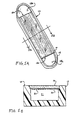
- Target substances labeled with the magnetically responsive colloidal particles described above can be collected in a collection vessel 10, shown in FIGS. 5A and 5B.
- the vessel 10 comprises a tub-shaped carrier member 12 having a recess formed therein, and a top wall member 14.
- the wall member 14 is configured to fit into the carrier member 12 to define a chamber 11 bounded by the interior surface of the wall member 14 and the interior surfaces of the carrier member 12.
- the wall member 14 is formed of a non-magnetic transparent material, such as glass, quartz or clear plastic.
- the carrier member 12 is also formed of a non-magnetic material, and is preferably also transparent.
- the wall member 14 covers a portion of the recess formed in carrier member 12 to provide orifices 16a and 16b at opposed longitudinal ends of the chamber 11.
- the exposed recessed portions 18a and 18b of the carrier member 12 provide receptacles into which a drop of test fluid may be placed for analysis. Such a fluid may then flow into the chamber 11. Entry of fluid into the chamber 11 can be enhanced by capillary action, if the chamber is sufficiently narrow.
- Fiducial reference marks may be formed or imprinted upon the wall member 14 to provide means for measuring the volume of fluid contained within the chamber 11.
- a ferromagnetic collection structure is supported by adhesion or formed upon the interior surface of the wall member 14.
- the ferromagnetic collection structure comprises a plurality of lithographically-defined ferromagnetic lines 20 formed upon the interior surface of the wall member 14.
- the walls of the chamber 11 are optionally coated with a material such as BSA, silicone, or a negatively charged surface coating to provide chemically or biologically inert exposed interior surfaces. It is important to eliminate a buildup of electrostatic charge upon the wall surfaces to limit non-specific binding of target particles or free magnetic material to the walls of the chamber.
- the ferromagnetic lines 20 When the vessel 10 is placed into a magnetic field, the ferromagnetic lines 20 will become magnetized.
- the magnetic gradients produced by such lines 20 are comparable to the gradients calculated for a circular wire having the same cross-sectional area.
- the width of the ferromagnetic lines will not affect the monolayering of the particles along the magnetic lines, but the width does affect the strength of the magnetic gradient.
- the gaps between the lines 20 are preferably at least twice the diameter of the target particles.
- a single line may be used for collection.
- the thickness of the magnetic lines is chosen to be on the order of magnitude of the magnetically responsive target entities to be collected, so that the target entities will align along opposite sides 7 of the lines in a monolayer. Therefore, the lines 20 may be on the order of thickness of the particles to be collected. Preferably, the lines 20 are thinner than the diameter of the entities to be collected. If the entities to be collected are human lymphocytes on the order of 10 ⁇ m in diameter and the ferromagnetic lines 20 are about 5 ⁇ m thick, the cells will align in a single layer about 10 ⁇ m thick. It is particularly preferred for the magnetic lines to be significantly thinner than the diameter of particles to be collected. For example, magnetic lines on the order of 0.25 ⁇ m may be used to collect entities of 10 ⁇ m in diameter.
- Such thin ferromagnetic lines can be manufactured by methods currently used in the manufacture of computer chips.
- the surface of the wall member is first coated with a ferromagnetic material by a vapor deposition technique, such as vacuum evaporation or sputtering.
- a vapor deposition technique such as vacuum evaporation or sputtering.
- Such a technique provides a layer of metal adhered to the eventual interior surface of the vessel.
- the combination of ferromagnetic material and the material used to form the wall member should be selected to provide sufficient adhesion of the ferromagnetic material to the wall member.
- a layer of photosensitive polymer, or photoresist is then applied to the coated surface of the wall member and exposed to a pattern of ultraviolet light corresponding to the desired pattern of the ferromagnetic capture structure (or a negative image thereof, depending upon the photoresist employed).
- the photoresist is then developed to render undesired portions of the metal coating susceptible to removal by etching, such as wet chemical etching or reactive ion etching.
- the lines may be formed by a lift-off procedure wherein a photoresist pattern is first applied to the wall member and is removed subsequent to deposition of a ferromagnetic coating.
- Such lithographic methods may be employed to produce a selected pattern of ferromagnetic metallization on a single wall member or upon a large-area substrate that is later to be divided into a plurality of wall members.
- These lithographic techniques can be substantially cheaper than the use of electroplating or electroforming, which would be used for thicker lines.
- Thin lines by their nature, also tend to be smoother than their thicker counterparts. Such consistency is a by-product of the manufacturing technique. Smoother lines are important, because the induced magnetic fields are likewise more consistent. Since such small lines are being used, the strength of the magnetic field will vary greatly along a relatively "bumpy" line, which will lead to clumping of the collected magnetic material.
- a smoother ferromagnetic capture structure and more consistent magnetic fields will result in more evenly spaced magnetic material, facilitating automated examination of the collected material.
- an exemplary target substance shall be human lymphocytes labeled with magnetic particles manufactured as described in U.S. Patent Nos. 4,795,698, 5,512,332 and 5,597,531 and in U.S. Patent Application No. 08/482,448.
- FIG. 6 shows the vessel 10 positioned in a substantially uniform magnetic field, shown by field lines 30, created in a gap between two magnets 21 of opposing polarity.
- the longitudinal axis of the ferromagnetic capture structure is oriented perpendicular to the field lines 30.
- FIG. 7 is a computer-generated diagram illustrating the paths 40 followed by numerous magnetically responsive particles 41 after the vessel is positioned in a homogeneous magnetic field. Magnetized ferromagnetic lines 20 with a thickness of 5 ⁇ m are shown end-on. A majority of particles in the chamber are unaffected by the internal magnetic gradients and eventually fall to the bottom of the chamber under the influence of gravity.
- a reproducible and high percentage of the particles would desirably be collected by the device.
- relatively rare events such as circulating tumor cells, fetal cells in maternal blood, or hematopoietic stem cells
- virtually all target particles must be collected.
- a method of "sweeping up" the cells in the chamber is necessary to move the particles into the spatially limited internal high gradient regions.
- One way of "sweeping up” particles would be to use a narrow chamber. As indicated in Fig.
- a chamber thickness of just under 100 ⁇ m is sufficient for 5 ⁇ m ferromagnetic lines, but this would require a small chamber volume, which would limit the opportunity to observe rare species.
- Using a long chamber to increase volume would require a longer ferromagnetic capture structure, and would increase the time needed to search along the capture structure for the collected target material.
- magnetically labeled material may not be able to move through a thick layer of settled non-target material to reach the ferromagnetic capture structure, resulting in loss of selectivity and crowding of the detection area.
- Another approach would be to increase the field strength of the magnets, but as shown in formula II, to double the range of the gradient, one would have to increase the external field strength eight-fold.
- One method of the instant invention uses a non-uniform applied magnetic field to magnetize the ferromagnetic capture structure and also to provide an external gradient perpendicular to the capture structure "sweep up" the magnetically responsive particles not initially located within the influence of the internal magnetic gradients.
- the applied magnetic field preferably supplies an external gradient of sufficient magnitude to transport the cells towards the ferromagnetic capture structure where they are then immobilized against the wall adjacent the capture structure by the internal magnetic gradient. Attributes of such a field include that it is substantially homogeneous within a plane parallel to the ferromagnetic capture structure, and that the field is oriented perpendicular to the horizontal longitudinal axis of the structure.
- the field includes a vertical external gradient component that increases in the direction toward the capture structure, and that the external gradient is high enough to transport magnetically-labeled material toward the capture structure.
- a magnetic field which could serve such dual purposes can be produced by various configurations of magnets.
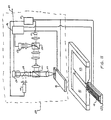
- One advantageous arrangement of external source magnets is shown in FIG. 8.
- FIG. 8 shows the separation vessel 10 positioned at a preferred location relative to a pair of opposed magnetic poles 23 and 24 having a gap formed therebetween.
- the lower surfaces of the poles 23 and 24 are tapered toward the gap, so that the magnetic field applied to the chamber is non-uniform, and has a substantially vertical gradient effective to urge magnetically-responsive particles within the chamber against the force of gravity toward the ferromagnetic collection structure on the upper wall.
- FIG. 9 shows the paths that would be followed by such particles within the chamber in the absence of the ferromagnetic collection structure. As can be seen, the influence of the externally-applied gradient is sufficient to move the particles substantially vertically toward the upper wall of the chamber.
- FIG. 10 shows the paths followed by particles within the chamber, including the effect thereon caused by the presence of a ferromagnetic collection structure comprising lithographically-defined lines having a thickness of 5.0 ⁇ m and a width of 20 ⁇ m.
- the externally applied gradient tends to urge particles initially located in the lower portion of the chamber to move into the high gradient regions generated by magnetization of the ferromagnetic lines.
- a pair of rare earth magnets (Crucible Magnets; Elizabethtown, Kentucky) having an internal magnetization of 1200 gauss and an acute taper angle of 20° separated by a distance of 5.0 mm to form a gap through which observations of collected entities could be made.
- the upper surface of the separation vessel was positioned 2.0 to 3.0 mm below the gap.
- Fig. 10 shows a chamber height of 200 ⁇ m, chamber heights of 1 mm have been modeled and actually used to collect and quantify magnetically labeled cells.
- Alignment of the target material in a monolayer also allows for the analysis to be conducted by automated means, such as mechanical automated cell counting technology.
- the target material can be illuminated through the transparent wall.member and the optical properties of the target material can be detected. Optical properties include the direct observation of the target material and the measurement of adsorbed, scattered or fluorescent light.
- the target material can be analyzed aided by the addition of a substrate or other compound.
- Other compounds include the use of probes which recognize a characteristic determinant of the target material, and nuclear, cytoplasmic or membrane dyes. These probes can be either inherently fluorescent, fluorescently tagged, or fluorescent only upon binding to the characteristic determinant. Differentiation of the target material, i.e., leukocytes, is thus possible with a specific binding substance which recognizes subsets of the target material.
- platelets can be selected by use of CD41 or CD61. Differentiation into subsets includes an analysis of their activation status (recognition by CD62p or PAC-1) or the presence of granules (recognition by CD63 or LDS-751). The immobilization of red blood cells is discussed elsewhere in this specification.
- a notable advantage of the apparatus and method of the invention is that the ability to provide linearly monolayered entities presents the opportunity to perform sequential reactions in a rapid and highly efficient manner.
- the apparatus and method of the invention be used to facilitate cell analysis for the determination of cell surface characteristics, e.g., T-Cell, B-Cell Progenitor cells and subset markers thereof, but they can in principle be applied for the analysis of intracellular components or genes.
- Such an analysis would be done by first capturing and aligning the cells of interest. This step would be followed by a series of sequential flow-by reactions, which would permeate the cell membrane, tag entities of interest and amplify signal on tagged entities. This capability provides a distinct advantage over existing cytometric technologies.
- a direct coated ferrofluid was prepared according to U.S. patent application 08/482,448.
- the ferrofluid particles were coated with CD45 antibody, which binds to leukocytes.
- the ferrofluid was stored in a HEPES buffer, pH 7.5 at 100 ⁇ g/ml.
- the target cells were CEM cells at a concentration of 5 x 10 6 cell/ml. 100 ⁇ l of cells were incubated with 10-30 ⁇ l of ferrofluid for ten minutes at room temperature before loading the collection chamber.
- a separation vessel was provided with a chamber having dimensions of 0.1 mm x 5 mm x 20 mm, for a chamber volume of 10 ⁇ l.
- the ferromagnetic capture structure comprised lithographically formed lines of nickel having dimensions of approximately 5 ⁇ m thick x 25 ⁇ m wide. The lines were spaced at 100 ⁇ m intervals.
- the magnetically labeled CEM cells were loaded into the collection chamber.
- the interior of the chamber was first observed in the absence of a magnetic field and almost all of the cells were observed to have settled at the bottom of the chamber.
- the chamber was then agitated to resuspend the cells.
- the collection chamber was placed into a magnetic field formed by two square magnets (such as the magnets shows in FIG. 2).
- the vessel was located in a non-uniform region of the field outside of the substantially uniform field directly between the magnets (i.e., at the location 33 shown in FIG. 6). Hence, an external gradient in the vertical direction was applied to the chamber to urge the magnetically responsive particles toward the ferromagnetic capture means.
- the collection chamber was positioned in the magnetic field, it was supported upon a microscope stage for observation of the cells were through a transparent wall of the chamber. Almost all of the target cells were observed to be aligned along the ferromagnetic capture lines in a single layer. Most of the cells were observed to be aligned after about ten seconds after the chamber was placed in the magnetic field. After a minute, all discernible cell movement ceased.
- the loaded chamber was placed in a substantially homogenous magnetic field as indicated by the chamber 10 shown in Fig. 6.
- the magnetized wires collected approximately 50% of the magnetically labeled CEM cells, a large number of cells settled to the bottom of the collection chamber.
- Example 3 The experiment of Example 3 was repeated with human whole blood. 100 ⁇ l of whole blood was incubated with 10-30 ⁇ l of the CD45 direct labeled ferrofluid described in example 1. After a ten minute incubation at room temperature, the collection chamber was loaded with 10 ⁇ l of test sample and positioned in the magnet arrangement described above. A short settling period of one minute was required to allow the non-target red cells to settle to the bottom of the chamber and away from the ferromagnetic capture means to allow observation of the target leukocytes cells. Upon microscopic examination, the target cells were seen to be aligned along upon the ferromagnetic capture lines. In other experiments with fluorescently labeled nucleated cells, no settling period was required to distinctly identify the collected target cells (i.e. leukocytes).
- the instant invention should also be useful for conducting competitive immunoassays. Proteins, hormones, or other blood components may be measured in whole blood using a device similar to that described in connection with FIGS. 1A and 1B. Magnetic particles which directly or indirectly bind to the blood components to be analyzed could be introduced into a blood sample, along with a fluorescent, chemiluminescent or other detectable probe, which binds directly or indirectly with the component to be analyzed. After the solution containing the blood, magnetically responsive particle, and detectable probe has been introduced into the device, the device is placed into a non-uniform magnetic field, and oriented such that gravity and the externally applied gradient act together to reinforce each other, instead of acting in opposition.
- the magnetically labeled protein, hormone, or other blood component will be drawn down to the magnetic collection structure.
- the excess detectable probe would remain in solution.
- the cellular components in the blood would also be drawn down towards the magnetic collection structure due to gravity.
- Detection of the non-bound detectable probe through fluorescence emission, chemiluminescence, or other means would be possible through a transparent wall of the collection device.
- the probe's signal, such as light emission, from the non-bound detectable probe would initially be blocked by cells, such red blood cells. Such cells would eventually settle to form a layer over the magnetic collection structure(s) to allow unobstructed detection of an emission fluorescence, or light scattering probe signal.
- the fringing field beneath a pair of opposed rectangular cross-section magnets is capable of providing the desired vertical external gradient while inducing internal magnetization of the ferromagnetic collection structure.
- the optical observation system is limited by a finite focal length such as less than 5mm, it is desirable to reduce the vertical distance between the top wall of the collection vessel and the top of the magnetic elements providing the field.
- such an objective can be achieved in a magnetic arrangement having two opposing pole faces separated by a gap, wherein the pole faces are formed to have tapering surfaces toward the gap, such as shown in FIG. 8.
- an automated observation system can be configured to provide relative motion between the vessel and the light gathering elements of the observation system in order to "track" the collected target entities for automated enumeration, which can include spectral analysis of light emitted or absorbed by the collected targets.
- the analysis system 100 comprises optical tracking and beam analysis components similar to those employed for reading compact discs known in the audio and data storage arts. Briefly, a pair of laser diodes 110 and 112 are connected with a power supply 114 to generate respective parallel beams of light. One beam is employed by the analysis system for locating and tracking lines of the ferromagnetic collection structure. The other beam is used for detecting the presence of collected target entities adjacent to a located line. Relative motion between the optical elements of the analysis system 100 is provided by a mechanical tracking unit 116. Coordination of the functions of the analysis system 100 is provided by a microprocessor 118.
- Laser 112 generates the tracking beam, which is transmitted through dichroic mirrors 120 and 122, and focussed upon the upper interior surface of the separation vessel 10 by objective lens 124.
- the tracking beam is reflected from the interior surface of the separation vessel, and is re-transmitted through dichroic mirrors 122 and 120 toward a photodetector 126.
- Photodetector 126 generates an electric signal in response to receiving the reflected light, which is provided to the microprocessor 118.
- the mechanical tracking unit 116 is operated by the microprocessor 118 to move the objective in the presumed direction of the'lines of the ferromagnetic collection structure.
- Microprocessor 118 is programmed to detect deviations within the electrical signal from photodetector 126 to provide a feedback signal to the mechanical tracking unit 116 for adjusting the position of the objective 124 in a direction perpendicular to the lines of the ferromagnetic collection structure.
- laser 110 is operated to generate a beam of light for detecting the presence of collected target entities.
- the light from laser 110 is transmitted through dichroic mirrors 128 and 122, and is focussed upon the upper interior surface of the collection vessel to form a spot adjacent to the focal point of the tracking beam.
- Light reflected by target entities will be transmitted through dichroic mirrors 122 and 128 toward photodetector 130.
- Photodetector 130 generates an electrical signal representative of the light reflected from the target entities, which is transmitted to microprocessor 118.
- Microprocessor 118 is programmed to monitor variations in the electrical signal from photodetector 130, in order to provide an analysis output signal, such as a counting signal at an output terminal 132. It will be appreciated that such an output signal can be further processed to provide information relative to the quantity and respective positions of the collected target entities.
- one laser could be used to illuminate the chamber, instead of two lasers as depicted in the analysis system 100.
- the laser could be eliminated entirely and the chamber could be illuminated with a light-emitting diode or other light source, including light sources that illuminate the chamber from the sides or from below.
- spectral analysis components such as optical filters and gratings, as well as illuminating components having various spectral characteristics, can be employed in an automated analysis system for conducting spectral analysis of light emitted from the collected entities as an objective lens of the analysis system is moved to track the ferromagnetic collection structure.
- the separation vessel may be mounted on a piezoelectric crystal 123 connected to an electric power source for vibrating the chamber at a desired frequency.
- Cell Frequency Cell Number Targets Cells 1:1-1:10 10,000-1,000/ ⁇ l granulocytes, lymphocytes 1:10-1:10 2 1,000-100/ ⁇ l monocytes, eosinophils 1:10 2 -1:10 3 100-10/ ⁇ l basophils 1:10 3 -1:10 4 10-1/ ⁇ l CD34+ cells 1:10 4 -1:10 5 1,000-100/ml CD34+, CD38- cells 1:10 5 -1:10 6 100-10/ml tumor cells 1:10 6 -1:10 7 10-1/ml tumor cells 1:10 7 -1:10 8 1,000-100/l tumor cells
- the amount of blood needed to reliably detect, enumerate and examine the target population needs to be substantially larger than 1 ⁇ l.
- One practical implication for the analysis of larger blood volumes is a substantially longer processing time.
- the erythrocytes in the sample are typically lysed, which is accompanied with a 10 fold dilution of the sample.
- the 10 ml volume of the lysed sample will thus require 2.78 hours for analysis. The need for enrichment of the target population and an increase in its concentration is thus clearly desired.
- a variety of enrichment methods can be employed to increase the concentration of the desired target in the sample to be analyzed, so that a sufficient number of target entities will be present in the separation vessel to permit detection. Success of these procedures is determined by carry over of non targets, recovery of targets, the ability to concentrate the target and the ability to accurately analyze the target after the procedure. Introduction into a separation vessel of a sample from a bodily fluid of which targets are concentrated and non targets are reduced, permits enumeration and examination of the target population.
- an external gradient separator of the type described in U.S. Patent No. 5,186,827 may be employed.
- a bioactive ferrofluid is added which identifies cells of epithelial origin.
- the sample is placed in the external gradient separator.
- the blood components not magnetically attached to the wall of the vessel are removed while the desired target substance remains adhered to the wall of the separator.
- the separated cells can now be resuspended into a smaller volume when the separation vessel is removed from the magnetic field.
- fluorescent labeled probes can be added to the resuspended sample. After incubation, the sample is again placed in an external gradient magnetic separator. After separation, the supernatant (including excess reagents) is removed, and the separated cells are resuspended in a volume commensurate with the chamber of a separation vessel of the present invention. Assuming the 10 ml of blood contained 10 8 cells, a carryover of 0.01% would result in 10 4 cells, which is within the range of the cell capture capacity of the apparatus of this invention. Given a target cell frequency of 1 in 10 7 and a capture efficiency of 70%, 7 target cells would be captured, which is sufficient for identification and further characterization.
- the cells which express the antigen targeted by the ferrofluid will align along the ferromagnetic lines in addition to other cells which are nonspecifically bound to the ferrofluid. Cells which were captured due to other reasons, such as entrapment, will.not align, resulting in a further purification of infrequent cell types.
- Identification and further characterization of the target cells can be obtained by the differences in the scattered and spectrum of the fluorescence light.
- An additional improvement can be achieved by utilization of a fluorescent form of the bioactive ferrofluid, the target cells can then be discriminated from non specifically bound cells by the amount of fluorescence emitted by the cells, i.e. the density of the antigen on the cell surface of the target cell is most likely different from the density of nonspecifically bound ferrofluid to non target cells.
- an optical detection system can be configured to identify and record the location of the target particles of interest. Once the location of the target cells has been detected and recorded, the immobilization vessel then can be examined by a more sophisticated optical detection system, such as a confocal microscope.
- a difficulty arises from having to perform multiple dilutions of the original blood sample prior to magnetically capturing the cell type of interest. After having performed multiple dilutions, determining the concentration of the captured species relative to the original blood volume requires knowledge of the precise dilution ratio and the magnetic capture efficiency. These quantities can be determined by adding concentration markers to the original blood sample.
- a first marker, for determining the dilution, comprises a known concentration of distinctly identifiable particles that are loaded with sufficient magnetically responsive material to be captured with substantially total efficiency.
- the second marker, for determining the magnetic capture efficiency of the target cells comprises a known concentration of distinctly identifiable particles that are loaded with approximately the same quantity of magnetically-responsive material as the target cell.
- the second marker can comprise magnetically responsive beads that have been formed with sufficient magnetic material to have a magnetic moment substantially equal to that of the ferrofluid-labeled target entities, and similar fluid transport behavior.
- the second marker may comprise magnetically inert bodies that are coated with a binding substance having substantially the same number of binding sites and binding affinity as the target cells.
- Other techniques can be used to provide the second marker with analogous collection behavior relative to the target entity. Such methods are discussed in the following examples.
- That portion of the sample not attached to the wall of the vessel is discarded, the vessel is removed from the magnetic field and the cells collected on the wall are resuspended in 2 ml of a solution, such as an isotonic buffer or a solution which permeabilizes the cell membrane.
- a solution such as an isotonic buffer or a solution which permeabilizes the cell membrane.
- the resuspended cells are placed in the magnetic field for 5 minutes and the sample not attached to the wall of the vessel is discarded.
- the cells collected on the wall are resuspended in 0.2 ml of a solution containing fluorescently labeled antibodies, for example, CD45 PerCP identifying leukocytes, anti EPCAM PE and/or anticytokeratin PE identifying epithelial cells.
- the sample may again be separated, excess antibodies discarded and the collected cells resuspended in a solution containing a nucleic acid dye with fluorescence properties which can be spectrally distinguished from the fluorescence produced by the fluorescent conjugated monoclonal antibodies.
- Leukocytes, epithelial cells, green and red beads can then be enumerated by the methods described herein or by traditional enumeration methods.
- Example 6 The cell analysis of Example 6 was repeated, except for the addition of 10,000 red and 10,000 green beads with respectively 500 and 5,000 antigens per bead to the blood. (Many of the antigens are cloned and recombinant proteins can be obtained which are recognized by the antibodies). This is followed by addition of the ferrofluid which identifies both beads and epithelial cells. In this example, an accurate estimate of the absolute number of target cells is obtained and it determines in addition whether the target cell specific ferrofluid works.
- An analysis sample prepared according to the procedure described above can then be quantitatively analyzed using flow cytometry, or with the apparatus described herein.
- the volume in the apparatus described herein is known, whereas the volume which passes through a flow cytometer has to be determined by the beads or by the actual measurement of the volume in which the flow cytometer measured the target events.
- sample dispensing techniques pipette
- reagents such as fluorescent nucleic acid dyes to facilitate identification of target cells and a known concentration of 10 ⁇ m beads, for example, 1,000 per ⁇ l, with physical properties which distinguish them from the target cells, and labeled with an amount of ferrofluid which is in the same range as that of the target cells, are introduced into a separation vessel of the present invention.
- a drop of blood is also introduced into the vessel by, for example, capillary action. The blood and fluid are mixed and incubated.
- the vessel is now introduced into a magnetic field and the target cells and beads are aligned along the ferromagnetic lines.
- beads can be added which have an amount of antigen which is similar to the amount of antigen on the target cells.
- this procedure further provides a method to determine the efficacy of the techniques and reagents used to select and detect the target material.
- Important parameters in hematology are hemoglobin and hematocrit, mean corpuscular volume (MCV), mean hemoglobin concentration (MCH), mean cellular hemoglobin concentration (MCHC) and red blood cell number (RBC).
- MCV mean corpuscular volume
- MCH mean hemoglobin concentration
- MCHC mean cellular hemoglobin concentration
- RBC red blood cell number
- a larger dilution of the blood is required as compared to leukocyte measurements or subsets thereof (on the order of a 1,000 fold higher concentration).
- a higher fluid volume can be used in the chamber in order to obtain a greater dilution. It also could be advantageous to reduce the chamber height to reduce the number of erythrocytes aligned.
- Erythrocytes can be identified and aligned by using an erythrocyte specific ferrofluid such as glycophorin A-labeled ferrofluid or transferrin-labeled ferrofluid, the latter recognizing only the immature reticulocytes, i.e., RNA containing erythrocytes. Erythrocytes bound to such ferrofluids can be distinguished from nucleated cells bearing the transferrin receptor by the absence of nuclear fluorescence. Alternatively, one could make use of the presence of hemoglobin in the erythrocytes to render the erythrocytes magnetically responsive.
- an erythrocyte specific ferrofluid such as glycophorin A-labeled ferrofluid or transferrin-labeled ferrofluid, the latter recognizing only the immature reticulocytes, i.e., RNA containing erythrocytes.
- Erythrocytes bound to such ferrofluids can be distinguished from nucleated cells bearing
- the iron present in hemoglobin can be reduced, or otherwise rendered magnetic according to a known procedure such that the red blood cells will be immobilizable by the internal gradients generated in the vicinity of the ferromagnetic lines.
- no ferrofluid is necessary to attract the erythrocytes to the ferromagnetic lines, and the rate at which they would be attracted toward the ferromagnetic lines would be proportional to the amount of hemoglobin in the cells.
- erythrocytes are aligned along the ferromagnetic lines, light scatter and absorption measurements of the individual cells can be performed which permit the assessment of size, volume and hemoglobin content according to procedures for conducting measurements in known hematology analyzers, and suitably adapted for use with the present apparatus.
- the ability to assess the shape of the individual erythrocytes provides clinically useful information.
- Elliptocyte, leptocyte, teardrop rbc, spherocytes, sickle cells, schistocyte, acanthocyte, echinocyte, stomatocyte, xerocyte are all red blood cell shapes associated with disease states which cannot be accurately defined by the assessment of erythrocytes in hematology analyzers.
- the erythrocytes can be further differentiated by the addition of probes which recognize erythrocytes subsets, such as CD71 or transferrin. The fluorescence or other detectable signal of the probe could thus be analyzed through the transparent wall member.
- Enhancement of the ability to assess red blood cell shapes could be significantly improved by measurement of the surface area of the cell membrane which can be achieved by the addition of a fluorescent membrane dye to the diluent fluid. Measurement of the total amount of fluorescence per cell is then proportional to the total amount of the membrane. From the surface area of the cell membrane and the analysis of the light scatter and fluorescence signals, the shape of the erythrocyte can be derived. The dilution of the blood sample can be determined by the addition of the beads to the diluent fluid, and the number and volume of the erythrocytes can be determined, the hematocrit (volume of cells/(total blood volume)) can also be determined according to the present method.
- lymphocytes One of the critical needs for the immune function is the ability of lymphocytes to re-circulate through the various tissues of the body. This circulation uses blood and lymph for transportation and the antigen receptors present on the lymphocyte surface enable the monitoring of any site where antigen could enter the bloodstream.
- Memory T cells specific for antigens which are associated with specific infectious diseases such as measles, mumps, tetanus, HIV or Lyme disease are infrequent. However, their number increases dramatically when antigen reenters the body.
- Monoclonal antibodies specific for disease specific T cells can be made and upon labeling with ferrofluid the antigen (disease)-specific Memory T cells can be aligned and enumerated. Alternately, all specific or subsets of T cells could be aligned. The apparatus of the current invention could then be used to determine specific responses of cell subsets to immunological stimuli.
- Sequential flow-by reactions of generic or disease specific antigens or other markers also could be used to determine the functional status and capability among other characteristics of the aligned cells.
- a particular advantage of the current invention is that the reaction of individual cells can be measured at various time points after stimulation. This type of analysis is an obvious advantage over the measurement of immune function by flowcytometry which permits only on opportunity to measure individual cell responses.
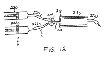
- Fluid supply means such as pumps, gravity reservoirs or syringes 220, 222 are provided for containing the test sample and respective reagents for reaction with the target material.
- Fluid conduits 224, 226 are provided for conducting flows of the respective fluids to a mixing valve 228.
- the mixing valve 228 is configured to select one or more of the fluid components for mixing and delivery to an inlet port 230 of the separation vessel 210.
- the separation vessel 210 further includes an outlet port 232 for conducting a flow of fluid out of the separation vessel 210.
- the separation vessel 210 is configured for use with magnetic arrangements and manual or automatic optical observation means such as have been described above, so that target material may be immobilized therein by a ferromagnetic capture structure 218, and then subjected to sequential reactions with the fluids provided by the fluid supply means and selected by the multi-port valve 228 in sequence and/or combination.
- the apparatus in FIG. 12 can be utilized to perform fluorescence in situ hybridization in order to differentiate among characteristics of cell subpopulations.
- the desired types of cells are immobilized in the apparatus.
- the cell membranes are permeabilized by an appropriate reagent prior to, or after, immobilization.
- in situ hybridization is performed on the immobilized, permeabilized cells by conducting sequential flows of reagents through the vessel.
- the respective reagents comprise respective fluorescent probes.
- the instant invention is particularly well adapted for performing sequential reactions due to the small size of the ferromagnetic lines relative to other internal gradient separators.
- the lines can be made relatively thin, due to the mechanical support provided by the wall of the vessel. Consequently, cells or other entities are rendered strongly immobilized by the relatively large internal gradients generated in the vicinity of the lines. Such strong immobilization force results in a greater resistance to hydraulic forces incident to conducting flow-by reactions on immobilized substances.
- magnetic capture structures were of significantly larger dimensions in order to provide an internal gradient with sufficient spatial extent to draw magnetic particles into immobilization.
- gravitational force and/or an applied external gradient can be employed to draw magnetizable entities toward a strong internal gradient region generated in the vicinity of a capture structure having relatively small dimensions, and supported along one side of the chamber of the separation vessel.
Landscapes
- Health & Medical Sciences (AREA)
- Immunology (AREA)
- Life Sciences & Earth Sciences (AREA)
- Chemical & Material Sciences (AREA)
- Engineering & Computer Science (AREA)
- Hematology (AREA)
- Biomedical Technology (AREA)
- Molecular Biology (AREA)
- Urology & Nephrology (AREA)
- Analytical Chemistry (AREA)
- General Health & Medical Sciences (AREA)
- Pathology (AREA)
- General Physics & Mathematics (AREA)
- Biochemistry (AREA)
- Physics & Mathematics (AREA)
- Cell Biology (AREA)
- Medicinal Chemistry (AREA)
- Food Science & Technology (AREA)
- Microbiology (AREA)
- Biotechnology (AREA)
- Chemical Kinetics & Catalysis (AREA)
- Electrochemistry (AREA)
- Clinical Laboratory Science (AREA)
- Investigating Or Analysing Biological Materials (AREA)
- Sampling And Sample Adjustment (AREA)
- Apparatus Associated With Microorganisms And Enzymes (AREA)
Claims (50)
- Gerät zur Beobachtung magnetisch reagierender mikroskopischer Teilchen, die in einem flüssigen Medium suspendiert sind, umfassend: ein Gefäß mit einer durchsichtigen Wand und einer darin geformten Kammer zur Aufnahme des flüssigen Mediums; eine ferromagnetische Fangkonstruktion, die in einem lithografischen Verfahren auf der durchsichtigen Wand geformt wird; und ein magnetisches Mittel zur Induzierung eines internen magnetischen Gefälles in der Nähe der ferromagnetischen Fangkonstruktion, wodurch die magnetisch reagierenden Teilchen über die Wand neben der Fangkonstruktion immobilisiert werden.
- Gerät nach Anspruch 1, dadurch gekennzeichnet, dass das Gefäß einen Flüssigkeitseinlass und einen Flüssigkeitsauslass zur Durchleitung einer Flüssigkeitsströmung durch das Gefäß umfasst.
- Gerät nach Anspruch 2, umfassend ein mit dem Flüssigkeitseinlass zur sequentiellen Zufuhr mehrerer Reagenzien zum Flüssigkeitseinlass verbundenes Flüssigkeitszufuhrmittel.
- Gerät nach einem der Ansprüche 1 bis 3, dadurch gekennzeichnet, dass die ferromagnetische Fangkonstruktion mehrere ferromagnetische Linien mit einem wirksamen Durchmesser unter 30 µm umfasst.
- Gerät nach einem der Ansprüche 1 bis 4, dadurch gekennzeichnet, dass das magnetische Mittel so ausgestaltet ist, dass es zum Transport von Teilchen im Gefäß in Richtung der Fangkonstruktion ein externes Gefälle an das Gefäß anlegt.
- Gerät nach einem der Ansprüche 1 bis 5, umfassend ein automatisches optisches Beobachtungssystem zum Nachweis und Zählen der immobilisierten Teilchen.
- Gerät nach Anspruch 6, dadurch gekennzeichnet, dass das automatische Beobachtungssystem Folgendes umfasst: einen optischen Detektor zum Nachweis der immobilisierten Teilchen; und Verfolgungsmittel zum Scannen des optischen Detektors parallel zu den ferromagnetischen Linien.
- Gerät zum Beobachten magnetisch reagierender mikroskopischer Teilchen, die in einem flüssigen Medium suspendiert sind, umfassend: ein Gefäß mit einer durchsichtigen Wand und einer darin geformten Kammer zur Aufnahme des flüssigen Mediums; eine ferromagnetische Fangkonstruktion, die auf der durchsichtigen Wand festgehalten wird; ein magnetisches Mittel zur Induzierung eines internen magnetischen Gefälles in der Nähe der ferromagnetischen Fangkonstruktion, wodurch die magnetisch reagierenden Teilchen über die Wand neben der Fangkonstruktions immobilisiert werden; und ein automatisches optisches Beobachtungssystem zum Nachweis und Zählen der immobilisierten Teilchen.
- Gerät nach Anspruch 8, dadurch gekennzeichnet, dass das automatische Beobachtungssystem folgendes umfasst: einen optischen Detektor zum Nachweis der immobilisierten Teilchen; und optische Verfolgungsmittel zum Scannen des optischen Detektors entlang der Fangkonstruktion.
- Gerät nach Anspruch 8, dadurch gekennzeichnet, dass das automatische Beobachtungssystem einen vibrationsfähigen Träger zum Unterstützen und selektiven Vibrieren des Gefäßes umfasst.
- Gerät nach Anspruch 10, dadurch gekennzeichnet, dass der vibrationsfähige Träger einen piezoelektrischen Vibrator umfasst.
- Gerät zum Beobachten magnetisch reagierender mikroskopischer Teilchen, die in einem flüssigen Medium suspendiert sind, umfassend: ein Gefäß mit einer durchsichtigen Wand und einer darin geformten Kammer zur Aufnahme des flüssigen Mediums; eine ferromagnetische Fangkonstruktion, die auf der durchsichtigen Wand festgehalten wird; ein magnetisches Mittel zur Induzierung eines internen magnetischen Gefälles in der Nähe der ferromagnetischen Fangkonstruktion und zum Anlegen eines externen Gefälles lotrecht zur ferromagnetischen Fangkonstruktion, wodurch die magnetisch reagierenden Teilchen zur Wand neben der Fangkonstruktion transportiert und darauf immobilisiert werden.
- Gerät nach Anspruch 12, dadurch gekennzeichnet, dass das magnetische Mittel ein Magnetpaar mit spitz zulaufenden Polflächen umfasst, die so angeordnet sind, dass dazwischen zur Aufnahme des Gefäßes eine Lücke entsteht.
- Gerät nach Anspruch 12-13, dadurch gekennzeichnet, dass die ferromagnetische Fangkonstruktion mehrere ferromagnetische Linien mit einem wirksamen Durchmesser unter 30 pm umfasst.
- Gerät nach Anspruch 14, dadurch gekennzeichnet, dass die ferromagnetischen Linien durch Adhäsion an der Wand gehalten werden.
- Gerät nach Anspruch 15, dadurch gekennzeichnet, dass die ferromagnetischen Linien durch ein lithografisches Verfahren auf der Wand geformt werden.
- Verfahren zur Immobilisierung mikroskopischer, magnetisch reagierender Teilchen, die in einem flüssigen Medium suspendiert sind, für Beobachtungszwecke, umfassend folgende Schritte: Bereitstellen eines Gefäßes mit einer Kammer mit einer durchsichtigen Wand und einer ferromagnetischen Fangkonstruktion, die auf der Wand festgehalten wird; Einführen des flüssigen Mediums in die Kammer; Anlegen eines Magnetfelds an die Kammer, um ein internes magnetisches Gefälle in der Nähe der ferromagnetischen Fangkonstruktion zu induzieren; und Beobachten der magnetisch reagierenden Teilchen, die neben der ferromagnetischen Fangkonstruktion gegen die Wand gehalten werden.
- Verfahren nach Anspruch 17, dadurch gekennzeichnet, dass die ferromagnetische Fangkonstruktion mehrere lineare ferromagnetische Elemente umfasst und der Beobachtungsschritt den Schritt des Scannens entlang den linearen ferromagnetischen Elementen mit einem automatischen optischen Nachweissystem umfasst.
- Verfahren nach Anspruch 17, dadurch gekennzeichnet, dass der Beobachtungsschritt den Schritt des Zählens der magnetisch reagierenden Teilchen umfasst.
- Verfahren nach einem der Ansprüche 17 bis 19, dadurch gekennzeichnet, dass der Anlegeschritt den Schritt der Orientierung des Gefäßes umfasst, um die ferromagnetische Fangkonstruktion so unter der Kammer anzuordnen, dass die magnetisch reagierenden Teilchen unter dem Einfluss der Schwerkraft zu der Fangkonstruktion transportiert werden.
- Verfahren nach einem der Ansprüche 17 bis 19, dadurch gekennzeichnet, dass der Anlegeschritt das Anlegen eines externen magnetischen Gefälles an das Gefäß zum Transport der magnetisch reagierenden Teilchen zur Fangkonstruktion umfasst.
- Verfahren zur Immobilisierung mikroskopischer, magnetisch reagierender Teilchen, die in einem flüssigen Medium suspendiert sind, für Beobachtungszwecke, umfassend folgende Schritte: Bereitstellen eines Gefäßes mit einer Kammer mit einer durchsichtigen Wand und einer ferromagnetischen Fangkonstruktion, die auf der Wand festgehalten wird; Einführen des flüssigen Mediums in die Kammer; Anlegen eines Magnetfelds mit einem externen Gefälle an die Kammer, um ein internes magnetisches Gefälle in der Nähe der ferromagnetischen Fangkonstruktion zu induzieren und magnetisch reagierende Teilchen zur Fangkonstruktion zu transportieren; Auffangen der magnetisch reagierenden Teilchen in einer linearen Monoschicht gegen die Wand und neben der ferromagnetischen Fangkonstruktion; und Beobachten der magnetisch reagierenden Teilchen, die neben der ferromagnetischen Fangkonstruktion gegen die Wand gehalten werden.
- Verfahren zur Differenzierung biologischer Substanzen zumindest einer ersten und zweiten Art in einer Flüssigkeitsprobe, umfassend folgende Schritte: Markieren der ersten und zweiten Art von biologischen Substanzen mit entsprechenden Markern zur Erzeugung deutlich unterscheidbarer optischer Eigenschaften; Hinzufügen einer Ferroflüssigkeit mit Bindungsaffinität für biologische Substanzen der ersten und zweiten Art zu der Flüssigkeitsprobe; Überführen der Flüssigkeitsprobe in ein Trenngefäß mit einer durchsichtigen Wand, die eine Seite einer Kammer definiert und einer ferromagnetischen Fangkonstruktion, die an der Wand festgehalten wird; Positionieren des Gefäßes in einem Magnetfeld zur Induzierung eines internen Gefälles in der Nähe der Fangkonstruktion, das ausreicht, um die biologischen Substanzen der ersten und zweiten Art entlang der Wand neben der Fangkonstruktion zu immobilisieren; und Beobachten der deutlich unterscheidbaren optischen Eigenschaften der ersten bzw. zweiten Art von biologischer Substanz.
- Verfahren nach Anspruch 23, dadurch gekennzeichnet, dass der Markierungsschritt folgendes umfasst: Hinzufügen erster und zweiter optischer Marker zu der Flüssigkeitsprobe zur Erzeugung deutlich unterscheidbarer optischer Reaktionen von biologischen Substanzen einer ersten Art bzw. einer zweiten Art; und dass der Beobachtungsschritt den Schritt des Beleuchtens des Gefäßes mit optischer Strahlung zur Erzeugung der deutlich unterscheidbaren optischen Reaktionen umfasst.
- Verfahren nach Anspruch 23 oder 24, dadurch gekennzeichnet, dass die ersten und zweiten biologischen Substanzen Zelltypen von Leukozyten-Unterpopulationen sind.
- Verfahren nach Anspruch 25, dadurch gekennzeichnet, dass die Leukozyten-Unterpopulationen lebende und tote Leukozyten enthalten.
- Verfahren nach Anspruch 23 oder 24, dadurch gekennzeichnet, dass die ersten und zweiten biologischen Substanzen erste bzw. zweite Erythrozyten-Unterpopulationen sind.
- Verfahren nach Anspruch 23 oder 24, dadurch gekennzeichnet, dass die ersten und zweiten biologischen Substanzen Zelltypen von Thrombozyten-Unterpopulationen sind.
- Verfahren nach Anspruch 23, dadurch gekennzeichnet, dass der Beobachtungsschritt die Beobachtung deutlich unterscheidbarer Formen der ersten bzw. zweiten Art von biologischen Substanzen umfasst.
- Verfahren nach Anspruch 23, dadurch gekennzeichnet, dass die biologischen Substanzen Zelltypen sind und der Beobachtungsschritt das Zählen der immobilisierten Zellen der ersten und zweiten Art und das Bestimmen eines Verhältnisses von immobilisierten Substanzen zur Nettooberfläche der immobilisierten Zellen umfasst.
- Verfahren nach Anspruch 23, umfassend folgende Schritte: Verdünnen der Flüssigkeitsprobe mit einem Verdünnungsmittel, das einen fluoreszierenden Membranfarbstoff enthält; und dadurch gekennzeichnet, dass der Beobachtungsschritt das Messen der Fluoreszenz von den immobilisierten Zellen zur Bestimmung der proportionalen Oberfläche der immobilisierten Zellen umfasst.
- Verfahren nach einem der Ansprüche 23 bis 31, umfassend den Schritt der Durchleitung sequenzieller Ströme von Reagenzien durch das Gefäß zur Erzeugung der deutlich unterscheidbaren optischen Reaktionen.
- Verfahren nach Anspruch 32, dadurch gekennzeichnet, dass die biologischen Substanzen jeweils Zellen bestimmter Zellunterpopulationen sind, wobei das Verfahren den Schritt der Permeabilisierung der Zellmembranen vor der Durchleitung der sequenziellen Ströme von Reagenzien durch das Gefäß umfasst.
- Verfahren nach Anspruch 32 oder 33, dadurch gekennzeichnet, dass die sequenziellen Ströme von Reagenzien sequenzielle Ströme von Reagenzien zur Erzeugung deutlich unterscheidbarer fluoreszierender optischer Reaktionen umfassen und dass der Beobachtungsschritt die Beleuchtung der immobilisierten Zellen mit einer Beleuchtung, die ausgewählt ist, um die deutlich unterscheidbaren fluoreszierenden Reaktionen zu erzeugen, umfasst.
- Verfahren nach Anspruch 23, dadurch gekennzeichnet, dass die biologische Substanz Zellen umfasst und der Beobachtungsschritt das Durchführen einer Hybridisierung in situ der immobilisierten Zellen umfasst.
- Verfahren zur Identifizierung immunophenotypischer Unterpopulationen von biologischen Substanzen, die in einem flüssigen Medium suspendiert sind, umfassend folgende Schritte: Hinzufügen einer Menge magnetisch reagierender Teilchen mit Bindungsaffinität für die biologischen Substanzen zu dem flüssigen Medium; Hinzufügen mehrerer Sonden mit voneinander unterscheidbaren Fluorochromen zu dem flüssigen Medium; Überführen des flüssigen Mediums in ein Trenngefäß mit einer durchsichtigen Wand, die eine Seite einer Kammer definiert und mit einer ferromagnetischen Fangkonstruktion, die an der Wand festgehalten wird; Positionieren des Gefäßes in einem Magnetfeld zur Induzierung eines internen Gefälles in der Nähe der Fangkonstruktion, das ausreicht, um die biologischen Substanzen entlang der Wand neben der Fangkonstruktion zu immobilisieren; Beleuchten des Gefäßes mit optischer Strahlung, die zumindest ein ausgewähltes Fluorochrom anregen kann; und Beobachten der optischen Reaktion des ausgewählten Fluorochroms.
- Verfahren zur Differenzierung von Erythrozyten-Unterpopulationen in einer Flüssigkeitsprobe, umfassend die folgenden Schritte: Behandlung von Erythrozyten in der Flüssigkeitsprobe, so dass sie magnetisch reagieren; Überführen des flüssigen Mediums in ein Trenngefäß mit einer durchsichtigen Wand, die eine Seite einer Kammer definiert und mit einer ferromagnetischen Fangkonstruktion, die an der Wand festgehalten wird; Positionieren des Gefäßes in einem Magnetfeld zur Magnetisierung der magnetisch reagierenden Erythrozyten und zur Induzierung eines internen Gefälles in der Nähe der Fangkonstruktion, das ausreicht, um die Zellen entlang der Wand neben der Fangkonstruktion anzuziehen und zu immobilisieren; und Beobachten der neben der Fangkonstruktion immobilisierten Erythrozyten.
- Verfahren nach Anspruch 37, dadurch gekennzeichnet, dass der Behandlungsschritt den Schritt der Markierung der Erythrozyten mit magnetisierbaren Teilchen umfasst.
- Verfahren nach Anspruch 38, dadurch gekennzeichnet, dass die magnetisierbaren Teilchen mit einer charakteristischen Determinante zumindest einer Unterpopulation von Erythrozyten binden können.
- Verfahren nach Anspruch 39, dadurch gekennzeichnet, dass die magnetisierbaren Teilchen zumindest eine Bindungssubstanz aus der Gruppe CD71, Glycophorin A und Transferrin umfassen.
- Verfahren nach einem der Ansprüche 37 bis 40, dadurch gekennzeichnet, dass der Beobachtungsschritt das Zählen von Erythrozyten-Unterpopulationen mit entsprechenden voneinander unterscheidbaren Formen umfasst.
- Verfahren nach einem der Ansprüche 37 bis 41, umfassend folgende Schritte: Verdünnen der Flüssigkeitsprobe mit einem Verdünnungsmittel, das einen fluoreszierenden Membranfarbstoff enthält; und dadurch gekennzeichnet, dass der Beobachtungsschritt das Messen der Fluoreszenz von den immobilisierten Zellen zur Bestimmung der proportionalen Oberfläche der immobilisierten Zellen umfasst.
- Verfahren zur Durchführung einer quantitativen Analyse der Zellen in einem ersten flüssigen Medium, umfassend folgende Schritte: Hinzufügen eines ersten Markers mit einer bekannten Menge erster magnetisch reagierender Teilchen zu dem ersten flüssigen Medium; Hinzufügen einer Menge zweiter magnetisch reagierender Teilchen mit Bindungsaffinität für die Zellen zu dem ersten flüssigen Medium; Überführen des ersten flüssigen Mediums in einem magnetischen Separator zum Trennen der magnetisch reagierenden Teilchen von anderen Bestandteilen des ersten flüssigen Mediums; Resuspendieren der getrennten magnetisch reagierenden Teilchen in einem zweiten flüssigen Medium; Zählen der Menge des ersten Markers und der Zellen in dem zweiten flüssigen Medium zum Bestimmen der Konzentration der Zellen in dem ersten flüssigen Medium, wobei der Zählschritt folgende Schritte umfasst: Überführen des zweiten flüssigen Mediums in eine Kammer eines Trenngefäßes mit einer durchsichtigen Wand und einer ferromagnetischen Fangkonstruktion, die an der Wand festgehalten wird; Positionieren dieses Trenngefäßes in einem Magnetfeld zur Erzeugung eines internen magnetischen Gefälles in der Nähe der ferromagnetischen Fangkonstruktion; und Zählen der gegen die durchsichtige Wand neben der ferromagnetischen Fangkonstruktion immobilisierten Zellen.
- Verfahren nach Anspruch 43, umfassend folgende Schritte: Hinzufügen eines zweiten Markers mit einer bekannten Menge dritter magnetisch reagierender Teilchen, deren Magnetmoment ungefähr dem der gebundenen Zellen entspricht, zu dem ersten flüssigen Medium; und dadurch gekennzeichnet, dass der Zählschritt den Schritt des Zählens der Menge des zweiten Markers in dem zweiten flüssigen Medium als Maß für die magnetische Trenneffizienz umfasst.
- Verfahren nach Anspruch 43 oder 44, umfassend den Schritt des Vorbereitens des zweiten Markers durch Bereitstellung einer Menge nicht magnetisch reagierender Teilchen mit einem Bindungsmittel für die zweiten magnetisch reagierenden Teilchen.
- Verfahren nach Anspruch 43, dadurch gekennzeichnet, dass der Zählschritt des Schritt des Bereitstellens des zweiten flüssigen Mediums zu einem Flusszytometer umfasst.
- Verfahren zur Messung eines hämatologischen Parameters einer Erythrozyten enthaltenden Flüssigkeitsprobe, umfassend: Verdünnen einer ersten Blut enthaltenden Flüssigkeitsprobe mit einem Verdünnungsmittel mit einer bekannten Menge erster magnetischer Teilchen zum Erhalt einer zweiten Flüssigkeitsprobe; Behandlung der Erythrozyten einer der ersten und zweiten Flüssigkeitsproben, so dass sie magnetisch reagieren; Überführen der zweiten Flüssigkeitsprobe in eine Kammer eines Trenngefäßes mit einer durchsichtigen Wand und einer ferromagnetischen Fangkonstruktion, die an der Wand festgehalten wird; Positionieren dieses Trenngefäßes in einem Magnetfeld zur Magnetisierung der Erythrozyten und zum Erzeugen eines internen magnetischen Gefälles in der Nähe der ferromagnetischen Fangkonstruktion; und Zählen der gegen die durchsichtige Wand neben der ferromagnetischen Fangkonstruktion immobilisierten Erythrozyten und ersten magnetischen Teilchen.
- Verfahren nach Anspruch 47, dadurch gekennzeichnet, dass der Behandlungsschritt den Schritt der Verbesserung der Magnetisierbarkeit der Erythrozyten durch Hinzufügen eines zweiten magnetischen Teilchens mit Bindungsaffinität für Erythrozyten zu einer der ersten und zweiten Flüssigkeitsproben umfasst.
- Verfahren nach Anspruch 47 oder 48, umfassend den Schritt des Hinzufügens einer bekannten Menge eines dritten magnetischen Teilchens mit einer magnetischen Eigenschaft, die der der durch Behandlung magnetisch reagierenden Erythrozyten entspricht, zu einer der ersten und zweiten Flüssigkeitsproben, und dadurch gekennzeichnet, dass der Zählschritt das Zählen der gegen die Fangkonstruktion immobilisierten dritten magnetischen Teilchen umfasst.
- Verfahren nach Anspruch 47 bis 49, umfassend den Schritt des Bestimmens auf Basis der Zählung zumindest eines der Parameter Hämoglobingehalt, Hämatokrit, mittleres Zellvolumen, mittlere Hämoglobinkonzentration und Erythrozytenzahl.
Applications Claiming Priority (5)
| Application Number | Priority Date | Filing Date | Title |
|---|---|---|---|
| US1928296P | 1996-06-07 | 1996-06-07 | |
| US19282P | 1996-06-07 | ||
| US3043696P | 1996-11-05 | 1996-11-05 | |
| US30436P | 1996-11-05 | ||
| PCT/US1997/009492 WO1997046882A1 (en) | 1996-06-07 | 1997-06-02 | Magnetic separation employing external and internal gradients |
Publications (3)
| Publication Number | Publication Date |
|---|---|
| EP0920627A1 EP0920627A1 (de) | 1999-06-09 |
| EP0920627A4 EP0920627A4 (de) | 1999-12-08 |
| EP0920627B1 true EP0920627B1 (de) | 2004-05-12 |
Family
ID=26692076
Family Applications (1)
| Application Number | Title | Priority Date | Filing Date |
|---|---|---|---|
| EP97929766A Expired - Lifetime EP0920627B1 (de) | 1996-06-07 | 1997-06-02 | Magnetische trennung mit hilfe von externen und internen gradienten |
Country Status (6)
| Country | Link |
|---|---|
| US (3) | US5985153A (de) |
| EP (1) | EP0920627B1 (de) |
| JP (1) | JP3996644B2 (de) |
| AU (1) | AU3374597A (de) |
| DE (1) | DE69729101T2 (de) |
| WO (1) | WO1997046882A1 (de) |
Cited By (8)
| Publication number | Priority date | Publication date | Assignee | Title |
|---|---|---|---|---|
| US8021614B2 (en) | 2005-04-05 | 2011-09-20 | The General Hospital Corporation | Devices and methods for enrichment and alteration of cells and other particles |
| US8137912B2 (en) | 2006-06-14 | 2012-03-20 | The General Hospital Corporation | Methods for the diagnosis of fetal abnormalities |
| US8168389B2 (en) | 2006-06-14 | 2012-05-01 | The General Hospital Corporation | Fetal cell analysis using sample splitting |
| US8195415B2 (en) | 2008-09-20 | 2012-06-05 | The Board Of Trustees Of The Leland Stanford Junior University | Noninvasive diagnosis of fetal aneuploidy by sequencing |
| US8304230B2 (en) | 2002-09-27 | 2012-11-06 | The General Hospital Corporation | Microfluidic device for cell separation and uses thereof |
| US8921102B2 (en) | 2005-07-29 | 2014-12-30 | Gpb Scientific, Llc | Devices and methods for enrichment and alteration of circulating tumor cells and other particles |
| US10591391B2 (en) | 2006-06-14 | 2020-03-17 | Verinata Health, Inc. | Diagnosis of fetal abnormalities using polymorphisms including short tandem repeats |
| US10704090B2 (en) | 2006-06-14 | 2020-07-07 | Verinata Health, Inc. | Fetal aneuploidy detection by sequencing |
Families Citing this family (205)
| Publication number | Priority date | Publication date | Assignee | Title |
|---|---|---|---|---|
| US6861053B1 (en) * | 1999-08-11 | 2005-03-01 | Cedars-Sinai Medical Center | Methods of diagnosing or treating irritable bowel syndrome and other disorders caused by small intestinal bacterial overgrowth |
| US6790366B2 (en) * | 1996-06-07 | 2004-09-14 | Immunivest Corporation | Magnetic separation apparatus and methods |
| US6890426B2 (en) * | 1996-06-07 | 2005-05-10 | Immunivest Corporation | Magnetic separation apparatus and methods |
| US6660159B1 (en) | 1996-06-07 | 2003-12-09 | Immunivest Corporation | Magnetic separation apparatus and methods |
| US7666308B2 (en) * | 1996-06-07 | 2010-02-23 | Veridex, Llc. | Magnetic separation apparatus and methods |
| US20050069923A1 (en) * | 1996-07-08 | 2005-03-31 | Mullis Kary Banks | Dual bead assays using cleavable spacers and/or ligation to improve specificity and sensitivity including related methods and apparatus |
| DE69818650T2 (de) * | 1997-03-25 | 2004-08-12 | Immunivest Corp., Wilmington | Gerät und methoden zum einfnag und zur analyse von partikel-einheiten |
| NZ516848A (en) * | 1997-06-20 | 2004-03-26 | Ciphergen Biosystems Inc | Retentate chromatography apparatus with applications in biology and medicine |
| WO1999041613A1 (en) | 1998-02-12 | 1999-08-19 | Immunivest | Methods and reagents for the rapid and efficient isolation of circulating cancer cells |
| US20010018192A1 (en) | 1998-02-12 | 2001-08-30 | Terstappen Leon W.M.M. | Labeled cells for use as an internal functional control in rare cell detection assays |
| US7282350B2 (en) | 1998-02-12 | 2007-10-16 | Immunivest Corporation | Labeled cell sets for use as functional controls in rare cell detection assays |
| US6596076B1 (en) * | 1998-06-30 | 2003-07-22 | Director-General Of Agency Of Industrial Science And Technology | Apparatus and method for altering the apparent effects of gravity |
| EP0977037B1 (de) * | 1998-07-31 | 2005-08-31 | Tecan Trading AG | Magnetseparator |
| US6361749B1 (en) | 1998-08-18 | 2002-03-26 | Immunivest Corporation | Apparatus and methods for magnetic separation |
| ATE404269T1 (de) * | 1998-11-30 | 2008-08-15 | Immunivest Corp | Verfahren und vorrichtung zur magnetischen trennung |
| JP4593672B2 (ja) * | 1998-11-30 | 2010-12-08 | ベリデックス・リミテッド・ライアビリティ・カンパニー | 磁気的セパレータ及びその方法 |
| CA2358069A1 (en) * | 1999-01-06 | 2000-07-13 | University Of Medicine And Dentistry Of New Jersey | Method and apparatus for separating biological materials and other substances |
| US7364921B1 (en) | 1999-01-06 | 2008-04-29 | University Of Medicine And Dentistry Of New Jersey | Method and apparatus for separating biological materials and other substances |
| US6551843B1 (en) * | 1999-01-29 | 2003-04-22 | Immunivest Corporation | Methods for enhancing binding interactions between members of specific binding pairs |
| AU760299B2 (en) * | 1999-02-17 | 2003-05-08 | De Beers Consolidated Mines Limited | Ferrohydrostatic separation method and apparatus |
| WO2000052446A1 (en) * | 1999-03-02 | 2000-09-08 | Qualigen, Inc. | Methods and apparatus for separation of biological fluids |
| WO2000060124A2 (en) | 1999-04-06 | 2000-10-12 | Yale University | Fixed address analysis of sequence tags |
| US20040129555A1 (en) * | 1999-04-09 | 2004-07-08 | Marchitto Kevin S. | Energy enhanced reaction catalysis and uses thereof |
| FR2792332B1 (fr) * | 1999-04-14 | 2001-07-27 | Labonord | Procede de preparation d'une suspension cytologique |
| EP1203227A4 (de) * | 1999-06-04 | 2003-01-02 | Bioseparations Inc | Pränatales diagnostisches testsystem und -verfahren |
| US6623982B1 (en) * | 1999-07-12 | 2003-09-23 | Immunivest Corporation | Increased separation efficiency via controlled aggregation of magnetic nanoparticles |
| JP2003527087A (ja) | 1999-08-13 | 2003-09-16 | イェール・ユニバーシティ | バイナリーコード化配列タグ |
| CA2381732A1 (en) * | 1999-08-21 | 2001-03-01 | John S. Fox | High sensitivity biomolecule detection with magnetic particles |
| US6264313B1 (en) | 1999-09-10 | 2001-07-24 | Nypro, Inc. | Fluid delivery manifold and method of manufacturing the same |
| US6682649B1 (en) | 1999-10-01 | 2004-01-27 | Sophion Bioscience A/S | Substrate and a method for determining and/or monitoring electrophysiological properties of ion channels |
| US6743639B1 (en) | 1999-10-13 | 2004-06-01 | Nve Corporation | Magnetizable bead detector |
| US6875621B2 (en) * | 1999-10-13 | 2005-04-05 | Nve Corporation | Magnetizable bead detector |
| US6692952B1 (en) * | 1999-11-10 | 2004-02-17 | Massachusetts Institute Of Technology | Cell analysis and sorting apparatus for manipulation of cells |
| US7537938B2 (en) * | 2000-04-28 | 2009-05-26 | Monogram Biosciences, Inc. | Biomarker detection in circulating cells |
| US20040009614A1 (en) * | 2000-05-12 | 2004-01-15 | Ahn Chong H | Magnetic bead-based arrays |
| US7169618B2 (en) * | 2000-06-28 | 2007-01-30 | Skold Technology | Magnetic particles and methods of producing coated magnetic particles |
| US6674058B1 (en) | 2000-09-20 | 2004-01-06 | Compucyte Corporation | Apparatus and method for focusing a laser scanning cytometer |
| DE10050029B4 (de) * | 2000-10-06 | 2004-09-23 | Stiftung Caesar | Chemischer Sensor mit magnetischen Partikeln |
| US20020164659A1 (en) * | 2000-11-30 | 2002-11-07 | Rao Galla Chandra | Analytical methods and compositions |
| FR2817967B1 (fr) * | 2000-12-08 | 2003-02-28 | Diagast | Procede de magnetisation de marqueurs chimiques ou biologiques |
| US6736978B1 (en) | 2000-12-13 | 2004-05-18 | Iowa State University Research Foundation, Inc. | Method and apparatus for magnetoresistive monitoring of analytes in flow streams |
| DE60215302T2 (de) * | 2001-01-05 | 2007-03-29 | Immunivest Corp., Wilmington | Einrichtungen und verfahren für bildobjekte |
| DE60214827T2 (de) | 2001-02-12 | 2007-03-29 | Immunivest Corp., Wilmington | Kassette als behälter eines probenexemplars für die optische analyse |
| US20020168663A1 (en) * | 2001-02-27 | 2002-11-14 | Phan Brigitte Chau | Methods for DNA conjugation onto solid phase including related optical biodiscs and disc drive systems |
| US20030092029A1 (en) * | 2001-06-06 | 2003-05-15 | Lee Josephson | Magneitc-nanoparticle conjugates and methods of use |
| US7285412B2 (en) * | 2001-07-27 | 2007-10-23 | Surface Logix Inc. | Device for magnetic immobilization of cells |
| US7169578B2 (en) * | 2001-07-27 | 2007-01-30 | Surface Logix, Inc. | Cell isolation and screening device and method of using same |
| US7169577B2 (en) * | 2001-07-27 | 2007-01-30 | Surface Logix, Inc. | Cell isolation and screening device and method of using same |
| US20030040129A1 (en) * | 2001-08-20 | 2003-02-27 | Shah Haresh P. | Binding assays using magnetically immobilized arrays |
| US7863012B2 (en) * | 2004-02-17 | 2011-01-04 | Veridex, Llc | Analysis of circulating tumor cells, fragments, and debris |
| US20030129665A1 (en) * | 2001-08-30 | 2003-07-10 | Selvan Gowri Pyapali | Methods for qualitative and quantitative analysis of cells and related optical bio-disc systems |
| WO2003023571A2 (en) * | 2001-09-12 | 2003-03-20 | Burstein Technologies, Inc. | Methods for differential cell counts including related apparatus and software for performing same |
| US8980568B2 (en) | 2001-10-11 | 2015-03-17 | Aviva Biosciences Corporation | Methods and compositions for detecting non-hematopoietic cells from a blood sample |
| US8986944B2 (en) | 2001-10-11 | 2015-03-24 | Aviva Biosciences Corporation | Methods and compositions for separating rare cells from fluid samples |
| US20030091976A1 (en) * | 2001-11-14 | 2003-05-15 | Ciphergen Biosystems, Inc. | Methods for monitoring polypeptide production and purification using surface enhanced laser desorption/ionization mass spectrometry |
| AU2002352735A1 (en) * | 2001-11-20 | 2003-06-10 | Burstein Technologies, Inc. | Optical bio-discs and microfluidic devices for analysis of cells |
| SE0103859D0 (sv) * | 2001-11-20 | 2001-11-20 | Sven Oscarsson | Novel artificial structures with magnetic functionality |
| EP1487969A4 (de) * | 2001-12-07 | 2008-07-09 | Dyax Corp | Verfahren und vorrichtung zum waschen von magnetisch reagierenden teilchen |
| US20040234898A1 (en) * | 2002-02-06 | 2004-11-25 | Batishko Charles R. | Magnetic flowcell systems and methods |
| US7764821B2 (en) * | 2002-02-14 | 2010-07-27 | Veridex, Llc | Methods and algorithms for cell enumeration in a low-cost cytometer |
| EP1474772A4 (de) * | 2002-02-14 | 2005-11-09 | Immunivest Corp | Verfahren und algorithmen zur zellenaufzählung in einem kostengünstigen zytometer |
| US7514270B2 (en) * | 2002-04-12 | 2009-04-07 | Instrumentation Laboratory Company | Immunoassay probe |
| JPWO2003102224A1 (ja) * | 2002-05-30 | 2005-09-29 | 富士電機ホールディングス株式会社 | 微生物または細胞の計数方法 |
| US9435799B2 (en) | 2002-07-31 | 2016-09-06 | Janssen Diagnostics, Inc. | Methods and reagents for improved selection of biological materials |
| US20040058333A1 (en) * | 2002-09-23 | 2004-03-25 | Bell Michael L. | Assay products and procedures |
| US7011794B2 (en) * | 2002-11-25 | 2006-03-14 | Immunivest Corporation | Upon a cartridge for containing a specimen sample for optical analysis |
| US7326573B2 (en) * | 2003-01-10 | 2008-02-05 | Beckman Coulter, Inc. | Assay procedures and apparatus |
| WO2004077021A2 (en) * | 2003-02-27 | 2004-09-10 | Lesko Stephen A | Standardized evaluation of therapeutic efficacy based on cellular biomarkers |
| AU2003209572A1 (en) * | 2003-03-08 | 2004-09-28 | Ecole Polytechnique Federale De Lausanne (Epfl) | Magnetic bead manipulation and transport device |
| CN100453624C (zh) * | 2003-04-23 | 2009-01-21 | 王文浩 | 纳米颗粒燃料油及其制备方法 |
| US20070160503A1 (en) * | 2003-06-13 | 2007-07-12 | Palaniappan Sethu | Microfluidic systems for size based removal of red blood cells and platelets from blood |
| US7282180B2 (en) * | 2003-07-02 | 2007-10-16 | Immunivest Corporation | Devices and methods to image objects |
| US20050079591A1 (en) * | 2003-07-08 | 2005-04-14 | Reich Daniel H. | Method and magnetic microarray system for trapping and manipulating cells |
| FR2863626B1 (fr) * | 2003-12-15 | 2006-08-04 | Commissariat Energie Atomique | Procede et dispositif de division d'un echantillon biologique par effet magnetique |
| AU2004237844B2 (en) | 2003-12-23 | 2011-01-27 | Therakos, Inc. | Extracorporeal photopheresis in combination with anti-TNF treatment |
| WO2005065267A2 (en) * | 2003-12-24 | 2005-07-21 | Massachusetts Institute Of Technology | Magnetophoretic cell clarification |
| US8398295B2 (en) | 2004-01-28 | 2013-03-19 | Drexel University | Magnetic fluid manipulators and methods for their use |
| US20050181353A1 (en) * | 2004-02-17 | 2005-08-18 | Rao Galla C. | Stabilization of cells and biological specimens for analysis |
| EP1776449A4 (de) * | 2004-03-03 | 2009-08-12 | Gen Hospital Corp | Magnetvorrichtung zur isolierung von zellen und biomolekülen in einer mikrofluidischen umgebung |
| US8211386B2 (en) | 2004-06-08 | 2012-07-03 | Biokit, S.A. | Tapered cuvette and method of collecting magnetic particles |
| US20050274650A1 (en) * | 2004-06-09 | 2005-12-15 | Georgia Tech Research Corporation | Blood separation systems in micro device format and fabrication methods |
| US8189899B2 (en) * | 2004-07-30 | 2012-05-29 | Veridex, Llc | Methods and algorithms for cell enumeration in a low-cost cytometer |
| CA2577299C (en) | 2004-08-17 | 2014-05-06 | Frank A. W. Coumans | A diagnostic imaging device for the analysis of circulating rare cells |
| US7391091B2 (en) * | 2004-09-29 | 2008-06-24 | Nve Corporation | Magnetic particle flow detector |
| US20060109468A1 (en) * | 2004-11-24 | 2006-05-25 | Evans Richard W | Devices, methods, and systems for measuring an optical property of a sample |
| US20060109467A1 (en) * | 2004-11-24 | 2006-05-25 | Evans Richard W | Devices, methods, and systems for measuring an optical property of a sample |
| CN101036043B (zh) * | 2004-12-07 | 2010-10-13 | 株式会社Eci | 细胞计测方法 |
| CA2595721C (en) * | 2004-12-22 | 2010-09-21 | Institutt For Energiteknikk | Method for forming a high-gradient magnetic field and a substance separation device based thereon |
| US20070026415A1 (en) * | 2005-07-29 | 2007-02-01 | Martin Fuchs | Devices and methods for enrichment and alteration of circulating tumor cells and other particles |
| US20070026414A1 (en) * | 2005-07-29 | 2007-02-01 | Martin Fuchs | Devices and methods for enrichment and alteration of circulating tumor cells and other particles |
| US20070026417A1 (en) * | 2005-07-29 | 2007-02-01 | Martin Fuchs | Devices and methods for enrichment and alteration of circulating tumor cells and other particles |
| US20070026413A1 (en) * | 2005-07-29 | 2007-02-01 | Mehmet Toner | Devices and methods for enrichment and alteration of circulating tumor cells and other particles |
| US7781228B2 (en) | 2005-04-07 | 2010-08-24 | Menon & Associates, Inc. | Magnetic resonance system and method to detect and confirm analytes |
| WO2006122083A2 (en) * | 2005-05-09 | 2006-11-16 | The General Hospital Corporation | Water relaxation-based sensors |
| US20070059680A1 (en) * | 2005-09-15 | 2007-03-15 | Ravi Kapur | System for cell enrichment |
| US20090181421A1 (en) * | 2005-07-29 | 2009-07-16 | Ravi Kapur | Diagnosis of fetal abnormalities using nucleated red blood cells |
| US20070026416A1 (en) * | 2005-07-29 | 2007-02-01 | Martin Fuchs | Devices and methods for enrichment and alteration of circulating tumor cells and other particles |
| US7901950B2 (en) * | 2005-08-12 | 2011-03-08 | Veridex, Llc | Method for assessing disease states by profile analysis of isolated circulating endothelial cells |
| US7777885B2 (en) * | 2005-08-17 | 2010-08-17 | Veridex, Llc | Diagnostic imaging device for the analysis of circulating rare cells |
| WO2007027843A2 (en) * | 2005-08-31 | 2007-03-08 | T2 Biosystems, Inc. | Nmr device for detection of analytes involving magnetic particles |
| US20070059774A1 (en) * | 2005-09-15 | 2007-03-15 | Michael Grisham | Kits for Prenatal Testing |
| US20070059719A1 (en) * | 2005-09-15 | 2007-03-15 | Michael Grisham | Business methods for prenatal Diagnosis |
| US20070059716A1 (en) * | 2005-09-15 | 2007-03-15 | Ulysses Balis | Methods for detecting fetal abnormality |
| US20070059683A1 (en) * | 2005-09-15 | 2007-03-15 | Tom Barber | Veterinary diagnostic system |
| US20070059718A1 (en) * | 2005-09-15 | 2007-03-15 | Mehmet Toner | Systems and methods for enrichment of analytes |
| US20070059781A1 (en) * | 2005-09-15 | 2007-03-15 | Ravi Kapur | System for size based separation and analysis |
| US9220831B2 (en) * | 2005-10-06 | 2015-12-29 | Children's Medical Center Corporation | Device and method for combined microfluidic-micromagnetic separation of material in continuous flow |
| CN101351118B (zh) | 2005-11-02 | 2015-05-27 | 特拉科斯有限公司 | 凋亡细胞在离体产生调节t细胞中的应用 |
| DE102005053463A1 (de) * | 2005-11-06 | 2007-05-10 | Aj Innuscreen Gmbh | Vorrichtung und Verfahren zur automatisierten Isolierung und Aufreinigung von Nukleinsäuren aus beliebigen komplexen Ausgangsmaterialien |
| US20070166730A1 (en) | 2006-01-19 | 2007-07-19 | Menon & Associates, Inc. | Magnetic resonance system and method to detect and confirm analytes |
| US8216855B2 (en) * | 2006-02-13 | 2012-07-10 | Agency For Science, Technology And Research | Method of processing a biological and/or chemical sample |
| US8337755B2 (en) * | 2006-03-13 | 2012-12-25 | Veridex, Llc | Operator independent programmable sample preparation and analysis system |
| US20070238169A1 (en) * | 2006-04-11 | 2007-10-11 | The Board Of Trustees Of The Leland Stanford Junior University | Cell sorter and culture system |
| CA2652027C (en) * | 2006-05-12 | 2017-06-06 | Immunivest Corporation | A laser illumination system in fluorescent microscopy |
| US8296088B2 (en) | 2006-06-02 | 2012-10-23 | Luminex Corporation | Systems and methods for performing measurements of one or more materials |
| EP2038655A2 (de) * | 2006-06-02 | 2009-03-25 | Luminex Corporation | Systeme und verfahren zur durchführung von messungen eines oder mehrerer materialien |
| US20080124721A1 (en) * | 2006-06-14 | 2008-05-29 | Martin Fuchs | Analysis of rare cell-enriched samples |
| CN101583722A (zh) | 2006-07-14 | 2009-11-18 | 阿维瓦生物科学股份有限公司 | 从生物学样品检测稀有细胞的方法和组合物 |
| EP1939629A3 (de) * | 2006-08-11 | 2011-03-09 | Samsung Electronics Co., Ltd. | Vorrichtung zur zentrifugalkraftbasierten Magnetpositionssteuerung sowie scheibenförmiges Mikrofluidiksystem |
| US20090002703A1 (en) * | 2006-08-16 | 2009-01-01 | Craig Edward Parman | Methods and systems for quantifying isobaric labels and peptides |
| US7807454B2 (en) * | 2006-10-18 | 2010-10-05 | The Regents Of The University Of California | Microfluidic magnetophoretic device and methods for using the same |
| CA2669045A1 (en) | 2006-11-08 | 2008-05-15 | T2 Biosystems, Inc. | Nmr systems for in vivo detection of analytes |
| US8003314B2 (en) | 2007-04-16 | 2011-08-23 | Diagnostic Hybrids, Inc. | Methods for direct fluorescent antibody virus detection in liquids |
| WO2008128243A1 (en) | 2007-04-16 | 2008-10-23 | Immunivest Corporation | A rapid, semi-automated method to detect respiratory virus infected cells in direct specimens |
| GB0724404D0 (en) * | 2007-05-29 | 2008-01-30 | Invitrogen Dynal As | A sample vessel retaining portion |
| US9199247B2 (en) * | 2007-05-29 | 2015-12-01 | Invitrogen Dynal As | Magnetic separation rack |
| US20110070657A1 (en) * | 2007-08-17 | 2011-03-24 | The General Hospital Corporation | Detecting ions and measuring ion concentrations |
| JP2010536565A (ja) * | 2007-08-23 | 2010-12-02 | シンベニオ・バイオシステムズ・インコーポレーテッド | 目標種用のトラップ用磁気選別システム |
| US20090263870A1 (en) * | 2007-09-10 | 2009-10-22 | Agency For Science, Technology And Research | System and method for amplifying a nucleic acid molecule |
| DE102007043281A1 (de) * | 2007-09-11 | 2009-05-28 | Sebastian Dr. med. Chakrit Bhakdi | Vorrichtung, Materialien und Verfahren zur Hochgradientenmagnetseparation biologischen Materials |
| US8421458B2 (en) * | 2007-09-28 | 2013-04-16 | T2 Biosystems, Inc. | NMR diagnostics by means of a plastic sample container |
| WO2009061481A1 (en) | 2007-11-06 | 2009-05-14 | T2 Biosystems, Inc. | Small magnet and rf coil for magnetic resonance relaxometry |
| CN101939648B (zh) * | 2008-01-07 | 2013-09-04 | 卢米耐克斯公司 | 生物靶标的免疫磁性捕获和成像 |
| WO2009091643A1 (en) * | 2008-01-07 | 2009-07-23 | Luminex Corporation | Isolation and enumeration of cells from a complex sample matrix |
| US7927561B2 (en) * | 2008-01-10 | 2011-04-19 | Becton, Dickinson And Company | Rapid particle detection assay |
| WO2009097159A1 (en) * | 2008-02-02 | 2009-08-06 | Tropical Health Systems Llc | A blood purification method and appartus for the treatment of malaria |
| WO2009117611A2 (en) * | 2008-03-19 | 2009-09-24 | Cynvenio Biosystems, Llc | Trapping magnetic cell sorting system |
| EP2271919A1 (de) * | 2008-04-16 | 2011-01-12 | Cynvenio Biosystems, Inc. | Magnetisches trennsystem mit vor- und nachbearbeitungsmodulen |
| US8569077B2 (en) | 2008-05-19 | 2013-10-29 | Veridex, Llc | Imaging of immunomagnetically enriched rare cells |
| WO2010012002A1 (en) * | 2008-07-25 | 2010-01-28 | Saryna Medical Corporation | Methods and systems for genetic analysis of fetal nucleated red blood cells |
| JP5926958B2 (ja) | 2008-10-29 | 2016-05-25 | ティー2 バイオシステムズ,インコーポレーテッド | 凝固時間のnmr検出 |
| US20110206560A1 (en) * | 2008-10-31 | 2011-08-25 | Koninklijke Philips Electronics N.V. | Biosensor with multi-chamber cartridge |
| WO2010068812A1 (en) | 2008-12-10 | 2010-06-17 | Abqmr, Inc. | Nuclear magnetic resonance apparatus, methods and associated technology |
| US8790916B2 (en) * | 2009-05-14 | 2014-07-29 | Genestream, Inc. | Microfluidic method and system for isolating particles from biological fluid |
| FR2946338B1 (fr) * | 2009-06-04 | 2012-12-28 | Arkema France | Procede de preparation de composes fluores olefiniques |
| DK2440941T3 (en) * | 2009-06-10 | 2017-08-28 | Cynvenio Biosystems Inc | Sheath flow devices and methods |
| CN102470373B (zh) * | 2009-07-17 | 2014-11-26 | 皇家飞利浦电子股份有限公司 | 用于富集磁性粒子的设备 |
| US8083069B2 (en) * | 2009-07-31 | 2011-12-27 | General Electric Company | High throughput magnetic isolation technique and device for biological materials |
| DE102009047801B4 (de) * | 2009-09-30 | 2014-06-12 | Siemens Aktiengesellschaft | Durchflusskammer mit Zellleiteinrichtung |
| DE102009055800B4 (de) | 2009-11-18 | 2013-01-03 | Fraunhofer-Gesellschaft zur Förderung der angewandten Forschung e.V. | System und ein Verfahren zur Detektion von in flüssigen Proben enthaltenen Analytmolekülen |
| US8187979B2 (en) * | 2009-12-23 | 2012-05-29 | Varian Semiconductor Equipment Associates, Inc. | Workpiece patterning with plasma sheath modulation |
| CN102762712A (zh) * | 2010-01-21 | 2012-10-31 | 百赛普有限公司 | 稀有细胞的磁性分离 |
| AU2011223789A1 (en) | 2010-03-01 | 2012-09-20 | Caris Life Sciences Switzerland Holdings Gmbh | Biomarkers for theranostics |
| US8774488B2 (en) | 2010-03-11 | 2014-07-08 | Cellscape Corporation | Method and device for identification of nucleated red blood cells from a maternal blood sample |
| CA2795776A1 (en) | 2010-04-06 | 2011-10-13 | Caris Life Sciences Luxembourg Holdings, S.A.R.L. | Circulating biomarkers for disease |
| US20110262989A1 (en) | 2010-04-21 | 2011-10-27 | Nanomr, Inc. | Isolating a target analyte from a body fluid |
| US8841104B2 (en) | 2010-04-21 | 2014-09-23 | Nanomr, Inc. | Methods for isolating a target analyte from a heterogeneous sample |
| US9476812B2 (en) | 2010-04-21 | 2016-10-25 | Dna Electronics, Inc. | Methods for isolating a target analyte from a heterogeneous sample |
| US9428547B2 (en) | 2010-04-21 | 2016-08-30 | Dna Electronics, Inc. | Compositions for isolating a target analyte from a heterogeneous sample |
| US8409807B2 (en) | 2010-10-22 | 2013-04-02 | T2 Biosystems, Inc. | NMR systems and methods for the rapid detection of analytes |
| US8563298B2 (en) | 2010-10-22 | 2013-10-22 | T2 Biosystems, Inc. | NMR systems and methods for the rapid detection of analytes |
| BR122020001802B1 (pt) | 2010-10-22 | 2021-05-18 | T2 Biosystems, Inc | métodos para detectar a presença de um patógeno em uma amostra de sangue total e para detectar um analito em uma amostra |
| US9050595B2 (en) | 2010-12-03 | 2015-06-09 | Abbott Point Of Care Inc. | Assay devices with integrated sample dilution and dilution verification and methods of using same |
| WO2012087297A1 (en) | 2010-12-21 | 2012-06-28 | Empire Technology Development Llc | Magnetic in-line purification of fluid |
| US20120252038A1 (en) | 2011-04-01 | 2012-10-04 | Chianese David A | Steroid receptor assays |
| CN103501912B (zh) | 2011-04-27 | 2017-10-24 | 贝克顿·迪金森公司 | 用于分离样品中磁性标记部分的设备和方法 |
| WO2013006774A1 (en) | 2011-07-07 | 2013-01-10 | Veridex, Llc | Genomic diagnostics using circulating endothelial cells |
| CN103917658B (zh) | 2011-07-13 | 2016-09-21 | T2生物系统公司 | 用于监测血块形成的nmr方法 |
| TW201312117A (zh) | 2011-07-28 | 2013-03-16 | Univ Pennsylvania | 用以診斷與漿液相關之腫瘤細胞的症狀及特性的方法及試劑 |
| WO2013021101A1 (en) | 2011-08-08 | 2013-02-14 | Thermo Fisher Scientific Oy | Method and apparatus for automated analysis |
| FI20115785A0 (fi) | 2011-08-08 | 2011-08-08 | Thermo Fisher Scientific Oy | Menetelmä ja laite automaattiseen analyysiin |
| WO2013043858A1 (en) | 2011-09-21 | 2013-03-28 | T2 Biosystems, Inc. | Nmr methods for endotoxin analysis |
| US20130075318A1 (en) * | 2011-09-23 | 2013-03-28 | Xiaojing Zhang | Apparatus for Isolating Rare Cells from Blood Samples |
| EP3524692A1 (de) | 2012-04-20 | 2019-08-14 | T2 Biosystems, Inc. | Zusammensetzungen und verfahren zur detektion der candida-spezies |
| JP6207933B2 (ja) * | 2012-08-31 | 2017-10-04 | 東芝メディカルシステムズ株式会社 | 検体検査装置 |
| CN104736718A (zh) | 2012-10-26 | 2015-06-24 | 贝克顿·迪金森公司 | 用于操纵流体样品中的组分的装置和方法 |
| DE102012023382A1 (de) | 2012-11-30 | 2014-06-18 | Hochschule Trier | Vorrichtung zum Abscheiden magnetischer oder magnetisierbarer Mikropartikel aus einer Suspension mittelsHochgradienten-Magnetseparation |
| US9739733B2 (en) | 2012-12-07 | 2017-08-22 | T2 Biosystems, Inc. | Methods for monitoring tight clot formation |
| US10000557B2 (en) | 2012-12-19 | 2018-06-19 | Dnae Group Holdings Limited | Methods for raising antibodies |
| US9804069B2 (en) | 2012-12-19 | 2017-10-31 | Dnae Group Holdings Limited | Methods for degrading nucleic acid |
| US9995742B2 (en) | 2012-12-19 | 2018-06-12 | Dnae Group Holdings Limited | Sample entry |
| US9551704B2 (en) | 2012-12-19 | 2017-01-24 | Dna Electronics, Inc. | Target detection |
| US9434940B2 (en) | 2012-12-19 | 2016-09-06 | Dna Electronics, Inc. | Methods for universal target capture |
| US9599610B2 (en) | 2012-12-19 | 2017-03-21 | Dnae Group Holdings Limited | Target capture system |
| CN103131634B (zh) * | 2013-02-25 | 2014-09-03 | 宁波美晶医疗技术有限公司 | 一种基于微磁场的免疫肿瘤细胞筛选系统 |
| US20140242603A1 (en) * | 2013-02-26 | 2014-08-28 | Glenn Yaguang Deng | Methods and apparatus for target cell magnetic enrichment, isolation and biological analysis |
| TWI529402B (zh) | 2013-07-26 | 2016-04-11 | 財團法人工業技術研究院 | 磁性液滴控制裝置及磁性液滴的控制方法 |
| KR101593545B1 (ko) * | 2014-05-29 | 2016-02-26 | 서울대학교 산학협력단 | 재사용이 가능한 화학적 또는 생물학적 센서 및 그 사용방법 |
| US10625272B2 (en) * | 2015-11-18 | 2020-04-21 | Industrial Technology Research Institute | Magnetic separator |
| WO2017127731A1 (en) | 2016-01-21 | 2017-07-27 | T2 Biosystems, Inc. | Nmr methods and systems for the rapid detection of bacteria |
| CN108698846B (zh) | 2016-03-07 | 2021-05-04 | X-Zell生物科技私人有限公司 | 用于识别罕见细胞的组合物和方法 |
| DE102016104808A1 (de) * | 2016-03-15 | 2017-09-21 | Als Automated Lab Solutions Gmbh | Vorrichtung zum Einsetzen in ein bildgebendes System |
| EP3429755A1 (de) * | 2016-03-18 | 2019-01-23 | Andrew Alliance S.A | Verfahren und vorrichtung zur kügelchenmanipulation in einer spitze einer flüssigkeitshandhabungsvorrichtung |
| CN106076611A (zh) * | 2016-05-12 | 2016-11-09 | 刘锡云 | 流动粒粉静电消除磁力分离器 |
| IT201700082112A1 (it) | 2017-07-19 | 2019-01-19 | Milano Politecnico | Dispositivo e metodo per la quantificazione di componenti corpuscolate e non corpusculate del sangue. |
| WO2019099429A1 (en) * | 2017-11-14 | 2019-05-23 | University Of Florida Research Foundation | Magnetic separation system and devices |
| US10696961B2 (en) | 2017-12-01 | 2020-06-30 | Global Life Sciences Solutions Usa Llc | Magnetic cell isolation techniques |
| US12077743B2 (en) | 2018-02-09 | 2024-09-03 | Global Life Sciences Solutions Usa Llc | Apparatus for fluid line management in a bioprocessing system |
| US11932842B2 (en) | 2018-02-09 | 2024-03-19 | Global Life Sciences Solutions Usa Llc | Bioprocessing apparatus |
| US11414639B2 (en) | 2018-02-09 | 2022-08-16 | Global Life Sciences Solutions Usa Llc | Bioprocessing vessel |
| US11920119B2 (en) | 2018-02-09 | 2024-03-05 | Global Life Sciences Solutions Usa Llc | Systems and methods for bioprocessing |
| US11371007B2 (en) | 2018-02-09 | 2022-06-28 | Global Life Sciences Solutions Usa Llc | System and method for fluid flow management in a bioprocessing system |
| DE102018105969A1 (de) | 2018-03-15 | 2019-09-19 | Innome Gmbh | Messsystem zur Einzelzelldetektion |
| IT201900000821A1 (it) | 2019-01-18 | 2020-07-18 | Milano Politecnico | Apparato per la quantificazione di componenti biologiche disperse in un fluido. |
| CN116930016B (zh) * | 2023-09-18 | 2023-11-28 | 江苏希诚新材料科技有限公司 | 一种纳米浆料沉降特性测试装置 |
Family Cites Families (17)
| Publication number | Priority date | Publication date | Assignee | Title |
|---|---|---|---|---|
| IL68507A (en) * | 1982-05-10 | 1986-01-31 | Univ Bar Ilan | System and methods for cell selection |
| US4735504A (en) * | 1983-10-31 | 1988-04-05 | Technicon Instruments Corporation | Method and apparatus for determining the volume & index of refraction of particles |
| US4989978A (en) * | 1986-04-04 | 1991-02-05 | Technicon Instruments Corporation | Method and apparatus for determining the count per unit volume of particles |
| US5053344A (en) * | 1987-08-04 | 1991-10-01 | Cleveland Clinic Foundation | Magnetic field separation and analysis system |
| DE68916843T2 (de) * | 1988-04-26 | 1995-02-02 | Nippon Telegraph & Telephone | Mikropartikel, Verfahren und Gerät zur Sammlung von Proben zur Verwendung bei der Markierung von Immunreaktionen und Verfahren und Gerät zur Bereitung von Proben. |
| US5030560A (en) * | 1988-11-04 | 1991-07-09 | Immucor, Inc. | Method for drying mammalian cells for use in solid phase immunoassays and articles incorporating same |
| AU4746590A (en) * | 1988-12-28 | 1990-08-01 | Stefan Miltenyi | Methods and materials for high gradient magnetic separation of biological materials |
| GB8927742D0 (en) * | 1989-12-07 | 1990-02-07 | Diatec A S | Process and apparatus |
| US5375606A (en) * | 1990-02-28 | 1994-12-27 | Zynaxis, Inc. | Bio-analytical separation method |
| US5200084A (en) * | 1990-09-26 | 1993-04-06 | Immunicon Corporation | Apparatus and methods for magnetic separation |
| US5541072A (en) * | 1994-04-18 | 1996-07-30 | Immunivest Corporation | Method for magnetic separation featuring magnetic particles in a multi-phase system |
| WO1994011078A1 (en) * | 1992-11-16 | 1994-05-26 | Immunivest Corporation | Magnetic immobilization and manipulation of biological entities |
| US5466574A (en) * | 1991-03-25 | 1995-11-14 | Immunivest Corporation | Apparatus and methods for magnetic separation featuring external magnetic means |
| US5646001A (en) * | 1991-03-25 | 1997-07-08 | Immunivest Corporation | Affinity-binding separation and release of one or more selected subset of biological entities from a mixed population thereof |
| US5451525A (en) * | 1992-02-14 | 1995-09-19 | Coulter Corporation | Method and materials for determining particle count in a flow cytometer |
| US5494831A (en) * | 1993-08-30 | 1996-02-27 | Hughes Aircraft Company | Electrochemical immunosensor system and methods |
| US5705059A (en) * | 1995-02-27 | 1998-01-06 | Miltenyi; Stefan | Magnetic separation apparatus |
-
1997
- 1997-06-02 US US08/867,009 patent/US5985153A/en not_active Expired - Lifetime
- 1997-06-02 US US08/867,008 patent/US5993665A/en not_active Expired - Lifetime
- 1997-06-02 EP EP97929766A patent/EP0920627B1/de not_active Expired - Lifetime
- 1997-06-02 DE DE69729101T patent/DE69729101T2/de not_active Expired - Lifetime
- 1997-06-02 AU AU33745/97A patent/AU3374597A/en not_active Abandoned
- 1997-06-02 JP JP50076198A patent/JP3996644B2/ja not_active Expired - Lifetime
- 1997-06-02 US US08/867,233 patent/US6013188A/en not_active Expired - Lifetime
- 1997-06-02 WO PCT/US1997/009492 patent/WO1997046882A1/en active IP Right Grant
Cited By (25)
| Publication number | Priority date | Publication date | Assignee | Title |
|---|---|---|---|---|
| US8372579B2 (en) | 2002-09-27 | 2013-02-12 | The General Hospital Corporation | Microfluidic device for cell separation and uses thereof |
| US8986966B2 (en) | 2002-09-27 | 2015-03-24 | The General Hospital Corporation | Microfluidic device for cell separation and uses thereof |
| US8304230B2 (en) | 2002-09-27 | 2012-11-06 | The General Hospital Corporation | Microfluidic device for cell separation and uses thereof |
| US8895298B2 (en) | 2002-09-27 | 2014-11-25 | The General Hospital Corporation | Microfluidic device for cell separation and uses thereof |
| US9174222B2 (en) | 2005-04-05 | 2015-11-03 | The General Hospital Corporation | Devices and method for enrichment and alteration of cells and other particles |
| US8021614B2 (en) | 2005-04-05 | 2011-09-20 | The General Hospital Corporation | Devices and methods for enrichment and alteration of cells and other particles |
| US8921102B2 (en) | 2005-07-29 | 2014-12-30 | Gpb Scientific, Llc | Devices and methods for enrichment and alteration of circulating tumor cells and other particles |
| US9017942B2 (en) | 2006-06-14 | 2015-04-28 | The General Hospital Corporation | Rare cell analysis using sample splitting and DNA tags |
| US10155984B2 (en) | 2006-06-14 | 2018-12-18 | The General Hospital Corporation | Rare cell analysis using sample splitting and DNA tags |
| US8372584B2 (en) | 2006-06-14 | 2013-02-12 | The General Hospital Corporation | Rare cell analysis using sample splitting and DNA tags |
| US11781187B2 (en) | 2006-06-14 | 2023-10-10 | The General Hospital Corporation | Rare cell analysis using sample splitting and DNA tags |
| US11674176B2 (en) | 2006-06-14 | 2023-06-13 | Verinata Health, Inc | Fetal aneuploidy detection by sequencing |
| US8168389B2 (en) | 2006-06-14 | 2012-05-01 | The General Hospital Corporation | Fetal cell analysis using sample splitting |
| US8137912B2 (en) | 2006-06-14 | 2012-03-20 | The General Hospital Corporation | Methods for the diagnosis of fetal abnormalities |
| US9273355B2 (en) | 2006-06-14 | 2016-03-01 | The General Hospital Corporation | Rare cell analysis using sample splitting and DNA tags |
| US9347100B2 (en) | 2006-06-14 | 2016-05-24 | Gpb Scientific, Llc | Rare cell analysis using sample splitting and DNA tags |
| US10704090B2 (en) | 2006-06-14 | 2020-07-07 | Verinata Health, Inc. | Fetal aneuploidy detection by sequencing |
| US10591391B2 (en) | 2006-06-14 | 2020-03-17 | Verinata Health, Inc. | Diagnosis of fetal abnormalities using polymorphisms including short tandem repeats |
| US9353414B2 (en) | 2008-09-20 | 2016-05-31 | The Board Of Trustees Of The Leland Stanford Junior University | Noninvasive diagnosis of fetal aneuploidy by sequencing |
| US9404157B2 (en) | 2008-09-20 | 2016-08-02 | The Board Of Trustees Of The Leland Stanford Junior University | Noninvasive diagnosis of fetal aneuploidy by sequencing |
| US10669585B2 (en) | 2008-09-20 | 2020-06-02 | The Board Of Trustees Of The Leland Stanford Junior University | Noninvasive diagnosis of fetal aneuploidy by sequencing |
| US8682594B2 (en) | 2008-09-20 | 2014-03-25 | The Board Of Trustees Of The Leland Stanford Junior University | Noninvasive diagnosis of fetal aneuploidy by sequencing |
| US8195415B2 (en) | 2008-09-20 | 2012-06-05 | The Board Of Trustees Of The Leland Stanford Junior University | Noninvasive diagnosis of fetal aneuploidy by sequencing |
| US8296076B2 (en) | 2008-09-20 | 2012-10-23 | The Board Of Trustees Of The Leland Stanford Junior University | Noninvasive diagnosis of fetal aneuoploidy by sequencing |
| US12054777B2 (en) | 2008-09-20 | 2024-08-06 | The Board Of Trustees Of The Leland Standford Junior University | Noninvasive diagnosis of fetal aneuploidy by sequencing |
Also Published As
| Publication number | Publication date |
|---|---|
| US5993665A (en) | 1999-11-30 |
| AU3374597A (en) | 1998-01-05 |
| EP0920627A4 (de) | 1999-12-08 |
| JP2000513437A (ja) | 2000-10-10 |
| EP0920627A1 (de) | 1999-06-09 |
| JP3996644B2 (ja) | 2007-10-24 |
| WO1997046882A1 (en) | 1997-12-11 |
| DE69729101T2 (de) | 2005-05-12 |
| DE69729101D1 (de) | 2004-06-17 |
| US6013188A (en) | 2000-01-11 |
| US5985153A (en) | 1999-11-16 |
Similar Documents
| Publication | Publication Date | Title |
|---|---|---|
| EP0920627B1 (de) | Magnetische trennung mit hilfe von externen und internen gradienten | |
| US6136182A (en) | Magnetic devices and sample chambers for examination and manipulation of cells | |
| WO1997046882A9 (en) | Magnetic separation employing external and internal gradients | |
| EP0970365B1 (de) | Gerät und methoden zum einfnag und zur analyse von partikel-einheiten | |
| US5622831A (en) | Methods and devices for manipulation of magnetically collected material | |
| US6890426B2 (en) | Magnetic separation apparatus and methods | |
| US6790366B2 (en) | Magnetic separation apparatus and methods | |
| US5876593A (en) | Magnetic immobilization and manipulation of biological entities | |
| US6013532A (en) | Methods for magnetic immobilization and manipulation of cells | |
| US6660159B1 (en) | Magnetic separation apparatus and methods | |
| US20070196820A1 (en) | Devices and methods for enrichment and alteration of cells and other particles | |
| JP4995079B2 (ja) | 血液の表現型を検査するための磁性流体の使用および関連用途 | |
| CA2827226C (en) | Devices and methods for separating magnetically labeled moieties in a sample | |
| US6699669B2 (en) | Multistage electromagnetic separator for purifying cells, chemicals and protein structures | |
| KR20130119933A (ko) | 다중특이성 포착 시약 및 칵테일형 검출 시약을 이용한 췌장 환자에서의 순환 종양 세포의 검출을 위한 방법 및 키트 | |
| AU2006292490A1 (en) | Devices and methods for magnetic enrichment of cells and other particles | |
| WO1994011078A1 (en) | Magnetic immobilization and manipulation of biological entities | |
| CA2352064C (en) | Magnetic separation apparatus and methods | |
| AU618736B2 (en) | Automated analyzer and method for screening cells or formed bodies for enumeration of populations expressing selected characteristics | |
| JP2795746B2 (ja) | 選択された特性を現わす集団についての細胞または形成体をスクリーニングする方法および装置 | |
| CA2533683C (en) | Magnetic separation apparatus and methods | |
| JP4593672B2 (ja) | 磁気的セパレータ及びその方法 |
Legal Events
| Date | Code | Title | Description |
|---|---|---|---|
| PUAI | Public reference made under article 153(3) epc to a published international application that has entered the european phase |
Free format text: ORIGINAL CODE: 0009012 |
|
| 17P | Request for examination filed |
Effective date: 19990104 |
|
| AK | Designated contracting states |
Kind code of ref document: A1 Designated state(s): DE FR GB IT |
|
| A4 | Supplementary search report drawn up and despatched |
Effective date: 19991026 |
|
| AK | Designated contracting states |
Kind code of ref document: A4 Designated state(s): DE FR GB IT |
|
| RIC1 | Information provided on ipc code assigned before grant |
Free format text: 6G 01N 33/553 A, 6B 03C 1/034 B, 6B 03C 1/035 B, 6G 01N 33/543 B |
|
| 17Q | First examination report despatched |
Effective date: 20011016 |
|
| GRAP | Despatch of communication of intention to grant a patent |
Free format text: ORIGINAL CODE: EPIDOSNIGR1 |
|
| GRAS | Grant fee paid |
Free format text: ORIGINAL CODE: EPIDOSNIGR3 |
|
| GRAA | (expected) grant |
Free format text: ORIGINAL CODE: 0009210 |
|
| AK | Designated contracting states |
Kind code of ref document: B1 Designated state(s): DE FR GB IT |
|
| REG | Reference to a national code |
Ref country code: GB Ref legal event code: FG4D |
|
| REF | Corresponds to: |
Ref document number: 69729101 Country of ref document: DE Date of ref document: 20040617 Kind code of ref document: P |
|
| ET | Fr: translation filed | ||
| PLBE | No opposition filed within time limit |
Free format text: ORIGINAL CODE: 0009261 |
|
| STAA | Information on the status of an ep patent application or granted ep patent |
Free format text: STATUS: NO OPPOSITION FILED WITHIN TIME LIMIT |
|
| 26N | No opposition filed |
Effective date: 20050215 |
|
| REG | Reference to a national code |
Ref country code: FR Ref legal event code: PLFP Year of fee payment: 20 |
|
| PGFP | Annual fee paid to national office [announced via postgrant information from national office to epo] |
Ref country code: DE Payment date: 20160524 Year of fee payment: 20 Ref country code: GB Payment date: 20160601 Year of fee payment: 20 |
|
| PGFP | Annual fee paid to national office [announced via postgrant information from national office to epo] |
Ref country code: FR Payment date: 20160516 Year of fee payment: 20 |
|
| PGFP | Annual fee paid to national office [announced via postgrant information from national office to epo] |
Ref country code: IT Payment date: 20160621 Year of fee payment: 20 |
|
| REG | Reference to a national code |
Ref country code: DE Ref legal event code: R071 Ref document number: 69729101 Country of ref document: DE |
|
| REG | Reference to a national code |
Ref country code: GB Ref legal event code: PE20 Expiry date: 20170601 |
|
| PG25 | Lapsed in a contracting state [announced via postgrant information from national office to epo] |
Ref country code: GB Free format text: LAPSE BECAUSE OF EXPIRATION OF PROTECTION Effective date: 20170601 |