EP0918357A2 - Batterieverbinder und elektrisches Steckverbindungsteil - Google Patents
Batterieverbinder und elektrisches Steckverbindungsteil Download PDFInfo
- Publication number
- EP0918357A2 EP0918357A2 EP98120970A EP98120970A EP0918357A2 EP 0918357 A2 EP0918357 A2 EP 0918357A2 EP 98120970 A EP98120970 A EP 98120970A EP 98120970 A EP98120970 A EP 98120970A EP 0918357 A2 EP0918357 A2 EP 0918357A2
- Authority
- EP
- European Patent Office
- Prior art keywords
- battery
- section
- conductor
- circuit
- exposed
- Prior art date
- Legal status (The legal status is an assumption and is not a legal conclusion. Google has not performed a legal analysis and makes no representation as to the accuracy of the status listed.)
- Withdrawn
Links
Images


Classifications
-
- H—ELECTRICITY
- H01—ELECTRIC ELEMENTS
- H01M—PROCESSES OR MEANS, e.g. BATTERIES, FOR THE DIRECT CONVERSION OF CHEMICAL ENERGY INTO ELECTRICAL ENERGY
- H01M50/00—Constructional details or processes of manufacture of the non-active parts of electrochemical cells other than fuel cells, e.g. hybrid cells
- H01M50/20—Mountings; Secondary casings or frames; Racks, modules or packs; Suspension devices; Shock absorbers; Transport or carrying devices; Holders
- H01M50/204—Racks, modules or packs for multiple batteries or multiple cells
- H01M50/207—Racks, modules or packs for multiple batteries or multiple cells characterised by their shape
- H01M50/216—Racks, modules or packs for multiple batteries or multiple cells characterised by their shape adapted for button or coin cells
-
- H—ELECTRICITY
- H01—ELECTRIC ELEMENTS
- H01M—PROCESSES OR MEANS, e.g. BATTERIES, FOR THE DIRECT CONVERSION OF CHEMICAL ENERGY INTO ELECTRICAL ENERGY
- H01M50/00—Constructional details or processes of manufacture of the non-active parts of electrochemical cells other than fuel cells, e.g. hybrid cells
- H01M50/50—Current conducting connections for cells or batteries
-
- H—ELECTRICITY
- H05—ELECTRIC TECHNIQUES NOT OTHERWISE PROVIDED FOR
- H05K—PRINTED CIRCUITS; CASINGS OR CONSTRUCTIONAL DETAILS OF ELECTRIC APPARATUS; MANUFACTURE OF ASSEMBLAGES OF ELECTRICAL COMPONENTS
- H05K1/00—Printed circuits
- H05K1/18—Printed circuits structurally associated with non-printed electric components
- H05K1/189—Printed circuits structurally associated with non-printed electric components characterised by the use of flexible or folded printed circuits
-
- H—ELECTRICITY
- H05—ELECTRIC TECHNIQUES NOT OTHERWISE PROVIDED FOR
- H05K—PRINTED CIRCUITS; CASINGS OR CONSTRUCTIONAL DETAILS OF ELECTRIC APPARATUS; MANUFACTURE OF ASSEMBLAGES OF ELECTRICAL COMPONENTS
- H05K3/00—Apparatus or processes for manufacturing printed circuits
- H05K3/30—Assembling printed circuits with electric components, e.g. with resistors
- H05K3/32—Assembling printed circuits with electric components, e.g. with resistors electrically connecting electric components or wires to printed circuits
- H05K3/325—Assembling printed circuits with electric components, e.g. with resistors electrically connecting electric components or wires to printed circuits by abutting or pinching; Mechanical auxiliary parts therefor
- H05K3/326—Assembling printed circuits with electric components, e.g. with resistors electrically connecting electric components or wires to printed circuits by abutting or pinching; Mechanical auxiliary parts therefor the printed circuit having integral resilient or deformable parts, e.g. tabs or parts of flexible circuits
-
- Y—GENERAL TAGGING OF NEW TECHNOLOGICAL DEVELOPMENTS; GENERAL TAGGING OF CROSS-SECTIONAL TECHNOLOGIES SPANNING OVER SEVERAL SECTIONS OF THE IPC; TECHNICAL SUBJECTS COVERED BY FORMER USPC CROSS-REFERENCE ART COLLECTIONS [XRACs] AND DIGESTS
- Y02—TECHNOLOGIES OR APPLICATIONS FOR MITIGATION OR ADAPTATION AGAINST CLIMATE CHANGE
- Y02E—REDUCTION OF GREENHOUSE GAS [GHG] EMISSIONS, RELATED TO ENERGY GENERATION, TRANSMISSION OR DISTRIBUTION
- Y02E60/00—Enabling technologies; Technologies with a potential or indirect contribution to GHG emissions mitigation
- Y02E60/10—Energy storage using batteries
Definitions
- the present invention relates generally to an electrical connector and, more particularly, to an electrical connector for use with a battery having upper and lower terminals.
- Batteries are in common use in portable and small electrical apparatus, such as calculators, clocks, wristwatches, hearing aids, IC cards, car alarm activators, etc., to provide an electric current to electronic components mounted therein, such as a circuit board, LED, or other electronic devices.
- electronic components mounted therein such as a circuit board, LED, or other electronic devices.
- the electrical connection between the battery and the electronic component is made by a pair of stamped and formed metal contacts.
- the two contacts often have a different configuration, and the assembly of the two parts into the apparatus housing increases the cost of the apparatus.
- the battery connector has a higher profile than is desired for some applications.
- an electrical connector member for a battery for mounting in an electrical apparatus containing an electronic component that provides electrical connection between the positive and negative battery terminals with first and second conductors of an electronic component by a circuit member having a set of substantially parallel circuit sections providing a space therebetween for receiving the battery and spaced apart a distance corresponding to the distance between said contacting surfaces of said battery, a bent section joining said circuit sections and a connecting section.
- a first conductor is provided on the circuit member having a first end exposed at one of said parallel circuit sections and positioned to make electrical contact with the contacting surface of one of the battery terminals and a second end exposed at said connecting section for making electrical connection to a first conductor of said electronic component; and a second conductor is provided having a first end exposed at the other of said parallel circuit sections and positioned to make electrical contact with the contacting surface of the other battery terminal, and a second end exposed at said connecting section for making electrical connection to a second conductor of said electronic component, with said second conductor passing through said bent section of said circuit member.
- an integral, one-piece connector element which is simple, low cost, and when folded around the battery has a very low profile.
- the battery connector element of the invention avoids the need for two separate stamped and formed contacts, and the assembly of two parts to a housing.
- a battery connector is provided incorporating the electrical connector member having means for applying a compressive force to said substantially parallel circuit sections of said circuit member to resilently deform dimples into firm electrical engagement with the battery terminals when said battery is mounted in said space.
- an IC card package having an enclosure for a circuit board, with said enclosure having front and rear ends, an electrical connector at said front end of said enclosure and a housing having a recess therein for a battery at the rear end of said enclosure with a flexible circuit member as described previously, mounted in said recess.
- the battery connector comprises a housing 22 that holds a battery 24, which may be in the form of a relatively flat, circular, button-type battery, although the present invention may be utilized with batteries of other configuration, provided that the batteries have terminals at their upper and lower ends.
- the housing 22 comprises a base 26 and a cover 28.
- a generally circular recess 30 is formed in the base for holding the battery connector member 32 of the invention, together with battery 24.
- the base 26 includes a support 34 on which there is mounted an electronic component 36, which is normally a circuit board, but could also be an LED or other electronic device.
- the electronic component 36 has two conductors 38 on its upper surface, only one of such conductors being shown in Fig. 1. If the component 36 is a circuit board, the conductors 38 would be conductive traces on the upper surface of the board that lead to electronic devices mounted on the board.
- the cover 28 has downwardly,,extending flanges 40 on its opposite sides, each formed with an inwardly,,extending projection 42 that fits within a recess 44 on the outside of the wall 46 of the base to provide a releasable detent-type mounting connection between the cover and the base.
- the battery 24 has an upper terminal 48 providing an upwardly,,facing contacting surface 50, and has a lower terminal 52 providing a downwardly,,facing contacting surface 54.
- the upper terminal 48 may be the negative terminal, and the lower terminal 52 may be the positive terminal of the battery, although the polarities of the battery may be reversed.
- Fig. 2 which best illustrates the battery connector member 32 of the present invention which is in the form of a U,,-shaped flexible circuit that, as seen in Fig. 1, is bent around one side of the battery 24.
- the connector member 32 has a circular upper circuit section 56 and a circular lower circuit section 58 that is generally parallel to the upper section and spaced from the upper section a distance corresponding generally to the distance between the battery-contacting surfaces 50 and 54.
- the flexible circuit connector member 32 includes a bent interconnecting section 60 that is joined to the edges 62, 64 of the upper and lower circuit sections 56, 58.
- the height of the bent section 60 is slightly greater than the height of the battery 24.
- connection section 66 On the side of the lower circuit section 58 of the connector member 32 generally diametrically opposed to the bent section 60 there is provided a connecting section 66 that extends laterally outwardly from the edge 64 of the lower section.
- the connecting section 66 embodies exposed flexible circuit conductors for making electrical connection to the conductors 38 on electronic component 36, as will be described in further detail below.
- the spaced-apart parallel circuit sections 56, and 58 of the connector member 32 define a space 68 therebetween that receives the battery 24.
- a resilient conductive dimple 70 extends downwardly from the lower surface 72 of the upper circuit section 56 of the connector member generally at the center of the circular upper section, while a resilient conductive dimple 74 projects upwardly from the upper surface 75 of the lower circuit section 58 of the connector member, likewise located at generally the center of the circular lower section, whereby the dimples 70 and 74 are generally vertically aligned with each other and face toward each other.
- the conductive dimples 70 and 74 are exposed to make electrical contact with the upwardly-facing contacting surface 50 of the upper terminal 48 of the battery, and with the downwardly-facing contacting surface 54 of the lower terminal 52 of the battery, respectively. Since the dimples are hollow, they may be resilently deformed when a vertically-directed compressive force is applied to the upper and lower circuit sections 56, 58 of the connector member 32.
- the height of the wall 46 (Fig. 1) of the base 26 of the connector housing 22 that forms the recess 30 is slightly less than the height of the battery 24 and the upper and lower circuit sections 56, 58 of the connector member 32 when the cover 28 is removed from the base 26.
- a vertical compressive force is applied to the upper and lower circuit sections of the connector member causing the dimples 70 and 74 to resiliently deform, which results in a firm electrical contact being made between the dimples and the terminals of the battery.
- Fig. 3 shows the flexible circuit blank 32a from which the battery connector member 32 shown in Figs. 1 and 2 is formed.
- the flexible circuit blank contains two conductors 76 and 78, the conductors being shown in hidden lines in Fig. 3 except for exposed ends 80 and 82 in the connecting section 66 of the connector member.
- the conductors are typically metal strips.
- the ends 80 and 82 of the conductors are exposed by cutting windows 83 in the upper and lower plastic sheets of the flexible circuit.
- the spacing of the exposed conductor ends 80 and 82 corresponds to the lateral spacing of the conductors 38 on the upper surface of the electronic component 36 shown in Fig. 1.
- the conductor 76 extends to the center of the lower circuit section 58 of the connector member where it is deformed to form the dimple 74.
- the second conductor 78 extends through the lower section 58, the interconnecting section 60 to the center of the upper section 56 where it is deformed to form the dimple 70.
- the dimples 70 and 74 project upwardly.
- the width of the interconnecting section 60 and the width of the connecting section 66 of the flexible circuit is less than one-half the radius of the circular circuit sections 56 and 58.
- the flexible circuit blank 32a is formed into U-shape, as illustrated in Figs. 1 and 2, with the bend occurring in the interconnecting section 60 of the flexible circuit.
- the connecting section 66 of the connector member is passed through a slot 90 in the wall 46 of the base to position the exposed ends 80 and 82 of the conductors 76 and 78 over the terminals 38 of the electronic component 36, whereby the conductors of the connector member and the component may be electrically joined by soldering, or by the use of a conductive adhesive.
- the upper circuit section 56 of the connector member 32 is raised or pivoted about the region of the bent section 60, as seen in Fig.
- the flexible circuit is preferably a single conductor layer flexible circuit having upper and lower plastic sheets 84, 86 forming an insulative substrate, with a single layer conductor 78 disposed therebetween.
- the conductor 78 terminates in an enlarged circular section that is exposed by cutting a circular hole 88 in the upper plastic sheet 84.
- the dimple 70 is formed into an upwardly-projecting, hollow resilient portion by applying a force, by the use of a suitable rounded tool, to the bottom of the flexible circuit.
- the plastic sheets 84 and 86 may be formed of a suitable polymer film, such as Mylar, while the conductors 76 and 78 of the flexible circuit are typically thin metal strips formed of copper.
- One method of manufacture is, to first bond (with adhesive) a foil of conductive material, e.g. a copper alloy, to the lower plastic sheet. Then the foil conductive material is etched to leave the conductors 76, 78. Next, the upper plastic sheet is formed with holes for the dimples 70, 74 and then bonded to the lower plastic sheet, with the etched foil sandwiched in-between.
- the dimple 74 in the lower section 58 of the connector member 32 is formed in the same manner as is the dimple 70.
- the dimples 70 and 74 preferably have a semi-hemispherical configuration. However, if desired, the dimples could be simply upwardly raised, curved sections in the metal strips that form the conductors, rather than using enlarged circular dimples as shown in Figs. 2 and 4, particularly if the battery is relatively large.
- the circuit that forms the battery connector member 32 may not necessarily be a flexible circuit, provided that the interconnecting section 60 is flexible so that the connector member may be bent around a battery.
- the lower plastic sheet of the flexible circuit could be somewhat rigid, except in the interconnecting section area 60, and the upper plastic sheet 84 could be eliminated so that the lower sheet in effect forms a substrate for the conductors 76 and 78.
- the battery connector member 32 of the present invention there is provided a simple, low cost, low profile product which avoids the need for separate stamped metal contacts that must be assembled separately in the connector body as in conventional battery connectors.
- the use of a one-piece flexible circuit is particularly advantageous in that it provides an integral connector element that can be readily mounted in a connector body for connecting the terminals of a battery to an electronic component.
- Figs. 5-13 illustrate an IC card incorporating a modified form of the battery connector of the present invention.
- the IC card is generally designated by reference numeral 100.
- the parts thereof that are identical to or correspond to the parts in the battery connector 20 illustrated in Figs. 1ä4 have been given identical reference numerals differentiated by prime marks.
- the IC card 100 is adapted for insertion into a slot in the side of a lap top or portable computer for mating with the host connector in the computer.
- the IC card may be a memory card, a PC card, such as a fax/modem or LAN card, etc.
- the IC card 100 includes an enclosure 102 and a rear connector assembly 104.
- the enclosure has a front end 106 and a rear end 108.
- the enclosure 102 comprises a top metal cover 110 and a lower metal cover 112.
- a rectangular plastic frame 114 is mounted in the enclosure 102 for supporting a circuit board 116 on which there are mounted electronic devices, not shown.
- An electrical connector 120 is mounted at the front end of the enclosure 102. This connector is adapted to mate with a host connector in the computer when the IC card is mounted through the slot in the side of the computer.
- the parts of the IC card described so far are conventional.
- the rear connector assembly 104 extends rearwardly from the rear 108 of the enclosure 102 of the IC card.
- the connector assembly 104 embodies a battery connector 20 and an I/O connector 122 that incorporate a combined integral battery-I/O connector element 124 of the present invention, best seen in Fig. 8.
- the rear connector assembly 104 of the IC card 100 has an elongated, generally flat housing comprising a common base 126, a battery cover 128, and a connector cover 130.
- the connector cover 130 may be retained on the base 126 by sonic welding, adhesive, etc.
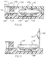
- the base 126 may be an integral extension of the plastic frame 114 in the IC card enclosure 102, or a separate part fixed to the frame, as shown in Fig. 10.
- the base 126 is formed with a profiled cavity 131 comprising two circular recesses 30 interconnected by a slot 132.
- the base also includes a rectangular cavity 134 which is separated from the cavity 131 by an upstanding wall 135 that has a narrow slot 136 therein.
- the base 126 includes at its forward end an upstanding flange 138.
- Slots 140, 142, and 144 extend through the flange into the interior of the IC card enclosure 102.
- the slots 140 and 144 are generally aligned with the centers of the recesses 30' , while the slot 142 is aligned with the slot 132.
- An additional slot 146 is formed in the flange 138 in front of the cavity 134.
- the slot 146 also opens into the interior of the enclosure 102.
- a notch 148 (Fig. 7) is formed in the rear wall 150 of the base 126 generally aligned with the slot 146.
- the notch 148 forms a slot, or I/O port, for receiving the front end 150 of a plug connector 152 connected to a cable 154.
- the front end 150 of the plug connector may be in the form of a printed circuit board having conductive traces 156 on its bottom surface which are electrically connected to the conductors in the cable 154
- a keyway 158 (Fig. 6) is formed in the inside surface of a side wall 160 of the base 126.
- the battery cover 128 is formed with an elongated key 162 on one side that has a sliding fit within the keyway 158 when the battery cover is slid forwardly over the recesses 30' in the base 126.
- the battery cover embodies two forwardly-extending projections 164 and 166 (Fig. 7) that are spaced apart a distance corresponding to the spacing between the slots 140 and 144 in the flange 138 of the base 126.
- the projections 164 and 166 are dimensioned to have a frictional fit within the slots 140 and 144 in the flange so that when the battery cover is slid forwardly to its forward-most position on the base the projections will project into said slots to retain the cover on the base.
- Upstanding pins 170, 172, and 174 are formed in the bottom of the base 126 to fit into holes, to be described later herein, in the combined battery-I/O connector element 124 to precisely locate the element in the base.
- the battery-I/O connector element 124 includes a dual battery connector member 180 and an I/O connector member 182 that are formed out of a single flexible circuit providing a one,,piece integral connector element.
- the battery connector member 180 includes a first set 183 of upper and lower parallel circuit sections 56 and 58 , and a second set 184 of upper and lower parallel circuit sections 56' and 58' .
- the upper and lower circuit sections 56' and 58' are similar to those described in connection with the battery connector member 32 illustrated in Figs. 1-4.
- the two upper circuit sections 56' are joined by an interconnecting part 185, while the lower circuit sections 58' are joined by an interconnecting part 186.
- the bent section 60' of the connector member is joined to the edges of the interconnecting parts 185 and 186.
- the connecting section 66' is joined to the edge of the interconnecting part 186 and extends laterally outwardly therefrom in a direction opposite to, but aligned with, the bent section 60'.
- the connecting section 66' has through windows 83' formed in the upper and lower sheets of the flexible circuit to expose conductors 80' and 82'.
- the connecting section 66' is dimensioned to have a sliding fit through the slot 142 (Fig. 6) in the flange 138 in the connector base 126 shown in Figs. 6 and 7.
- the two sets 183 and 184 (Fig. 8) of upper and lower parallel sections of the battery connector member are formed with dimples 70' and 74' which may be the same as the dimples 70 and 74 incorporated in the battery connector member 32.
- the dimples are positioned to engage the upper and lower terminals 48' , 52' of two batteries 24' mounted between the two sets of upper and lower circuit sections 56' and 58' of the battery connector member 124.
- the I/O connector member 182 of the connector element 124 is an integral extension of that portion of the flexible circuit that forms the battery connector member 180.
- the extension includes a flat lower portion 190 and angular upper portion 192.
- the flat lower portion 190 of the extension is connected to the lower circuit section 58' of the second set 184 of parallel circuit sections of the battery connector member 180 by a laterally-extending interconnecting part 191.
- the interconnecting part is dimensioned to fit within the slot 136 (Fig. 6) in the wall 135 of the connector base 126.
- the angular upper portion 192 (Fig. 8) extends upwardly and rearwardly from a bend 194 in the flexible circuit.
- a connecting section 196 which is similar to the connecting section 66' of the battery connector member 180, extends laterally outwardly from the flat lower portion 190 of the flexible circuit in a direction away from the bend 194.
- the connecting section has a window 198 extending therethrough in which there are exposed a plurality of conductors 200, five being shown by way of example only.
- the opposite ends 202 of the conductors are exposed on the upper surface of the angular upper portion 192 of the I/O connector member by removing the upwardly-facing plastic sheet of the flexible circuit at the point of the strip line 204 shown in Fig. 8.
- the connecting section 196 is dimensioned to have a sliding fit through the slot 146 (Fig. 6) in the flange 138 of the connector base 126.
- the first and second sets 183 and 184 (Fig. 8) of the parallel circuit sections of the battery connector member 180 are configured to have a sliding fit within the profiled cavity 131 (Fig. 6) in the base 126 of the rear connector assembly 122.
- the lower flat portion 190 (Fig. 8) of the I/O connector member is configured to have a sliding fit within the rectangular cavity 134 in the base.
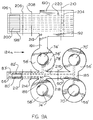
- a flexible circuit blank 124a from which the combined battery-I/O connector element 124 of Fig. 8 is formed.
- the conductors 76' and 78' in the battery connector section of the flexible circuit are arranged to connect two batteries 24' in parallel.
- the conductor 78' extends through the interconnecting part 186, bent section 60' and interconnecting part 185, where it splits and runs to the dimples 70'.
- the other conductor 76' runs from each of the dimples 74' through the interconnecting part 186 and the connecting section 66
- the phantom lines 206, 208, 210, 212, 214, and 216 shown in Fig. 9A indicate bend lines where the flexible circuit is bent into the configuration illustrated in Fig. 8.
- Circular holes 218, 219, and 220 are cut through the flexible circuit, and are arranged to receive the positioning pins 170, 172, and 174 (Fig. 6) when the connector element 124 is mounted in the base 126 of the rear connector assembly 122.
- the pins may be slightly higher than the thickness of the flexible circuit so the upper ends of the pins may be deformed by heat or otherwise to firmly secure the lower part of the connector element 124 in the base.
- the connecting sections 66' and 196 of the connector element are inserted through the slots 142 and 146 in the flange 138 of the base so that the exposed conductor end 80' , 82' , and 200 of the battery and I/O connector sections of the connector element will overlie conductive traces on the circuit board 116.
- the conductors may be soldered to the traces, or electrically connected thereto by the use of a conductive adhesive.
- the cover 130 may be mounted over the I/O section of the base and secured thereto by sonic welding, adhesive, or the like.
- the upper circuit sections 56' of the dual battery connector member 180 are raised as shown in Fig. 11, and the two batteries 24' are placed on the lower circuit sections 58' of the connector member.
- the upper circuit sections 56' are then pivoted downwardly over the batteries and the battery cover 128 (Fig. 10) is slid forwardly to apply a compressive force downwardly on the battery connector assembly in the same manner as described in connection with the embodiment illustrated in Figs. 1-4.
- the compressive force resiliently deforms the dimples 70' and 74' to produce a firm electrical contact between the dimples and the terminals of the battery.
- a bevel 221 is formed at the forward inner edge of the cover 128 to facilitate movement of the cover over the battery connector assembly.
- the projections 164 and 166 on the forward end of the cover 128 have a frictional engagement within the slots 140 and 144 in the flange 138 so as to firmly retain the cover on the base 126.
- connecting section 66' of the battery connector 180 is shown extending laterally outwardly from the interconnecting part 186 of the flexible circuit, it would also be possible to eliminate such connecting section. Instead, the conductors 80' and 82' could run through the interconnecting part 191 and the flat lower portion 190 to the connecting section 196 of the I/O connector portion of the connector element 124. As a result, all the conductors can be connected to the conductive traces on the circuit board 116 at one position on the board.
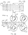
- Fig. 9B shows an alternative flexible circuit blank from which a modified form of the battery-I/O connector element of the invention may be formed.
- the flexible circuit blank of Fig. 9B differs from the element 124a in that the windows 83' and 198 in the connecting sections of the connector element are eliminated, and the conductors are exposed by simply removing portions of the plastic sheets of the flexible circuit.
- the flexible circuit blank shown in Fig. 9B is a double conductor layer flexible circuit having two layers of conductors (metal strips) separated by an intermediate plastic sheet, and outer plastic sheets covering the upper and lower conductor layers. The conductors shown in phantom in Fig.
- FIG. 9B are those lying in the lower layer of conductors, while the conductors shown in full lines are in the upper layer of the conductors.
- the lower sheet of plastic forming the flexible circuit blank shown in Fig. 9B is cut and stripped away at strip lines 222, 224, and 226 exposing the conductors 202', 200', 80', and 82' at the connecting sections 196 and 66'.
- an upper layer conductor 82'' directly connects the dimples 74' by running through the interconnecting part 186 and the conductor 82'' is electrically connected to the conductor 82' in the lower level which is exposed when the lower plastic sheet is removed at the strip line 226.
- the conductors 80' , 82' , and 200' are exposed only on the bottom of the connecting sections 196 and 66' , so that such conductors would be electrically connected to the conductive traces on the circuit board 116 by an adhesive paste, rather than by soldering.
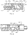
- Figs. 12 and 13 show the I/O connector member 182 mounted in the rear connector assembly 122.
- the angular upper portion 192 of the connector member 182 is positioned in front of the slot 148 so that the conductors 202 on the upper face of the angular portion face the slot.
- Fig. 13 shows the plug connector 152 with its forward end 150 extending through the slot 148 to cause the angular upper portion 192 of the I/O connector member to deflect downwardly, thereby providing a resilient electrical connection between the conductive traces 156 on the bottom 150 of the plug connector and the conductors 202.
- the plug connector 152 may embody a latching feature (not shown) which releasably attaches the plug connector to the rear connector assembly 122 or, alternatively, the plug connector 152 may be only temporarily inserted through the slot 148 to perform a function of programming the devices on the circuit board 116.
- Figs. 5-13 provides a simple, low cost, low profile connector element for making both electrical connections of two batteries in parallel to an electronic component, such as a circuit board, and electrical connection between an external connector (such as a plug connector) and the electronic component.
Landscapes
- Engineering & Computer Science (AREA)
- Chemical & Material Sciences (AREA)
- Chemical Kinetics & Catalysis (AREA)
- Electrochemistry (AREA)
- General Chemical & Material Sciences (AREA)
- Microelectronics & Electronic Packaging (AREA)
- Metallurgy (AREA)
- Manufacturing & Machinery (AREA)
- Battery Mounting, Suspending (AREA)
- Connection Of Batteries Or Terminals (AREA)
- Coupling Device And Connection With Printed Circuit (AREA)
Applications Claiming Priority (2)
| Application Number | Priority Date | Filing Date | Title |
|---|---|---|---|
| US975132 | 1997-11-20 | ||
| US08/975,132 US5993248A (en) | 1997-11-20 | 1997-11-20 | Battery connector |
Publications (1)
| Publication Number | Publication Date |
|---|---|
| EP0918357A2 true EP0918357A2 (de) | 1999-05-26 |
Family
ID=25522727
Family Applications (1)
| Application Number | Title | Priority Date | Filing Date |
|---|---|---|---|
| EP98120970A Withdrawn EP0918357A2 (de) | 1997-11-20 | 1998-11-05 | Batterieverbinder und elektrisches Steckverbindungsteil |
Country Status (7)
| Country | Link |
|---|---|
| US (1) | US5993248A (de) |
| EP (1) | EP0918357A2 (de) |
| JP (1) | JPH11233088A (de) |
| KR (1) | KR100284962B1 (de) |
| CN (1) | CN1218301A (de) |
| MY (1) | MY114075A (de) |
| TW (1) | TW388137B (de) |
Cited By (6)
| Publication number | Priority date | Publication date | Assignee | Title |
|---|---|---|---|---|
| EP2640170A1 (de) * | 2007-01-06 | 2013-09-18 | Apple Inc. | Drahtloses Headset mit einem Gehäuse und einem Ohrhörer, der über eine flexible Leiterplatte elektrisch an das Gehäuse gekoppelt ist |
| EP2702842A4 (de) * | 2011-04-25 | 2014-10-01 | Soligie Inc | Schaltelement-kupplungsvorrichtungen und verfahren für flexible und andere schaltungen |
| US9287657B2 (en) | 2005-09-26 | 2016-03-15 | Apple Inc. | Headset connector |
| GB2532781A (en) * | 2014-11-28 | 2016-06-01 | Skf Ab | An assembly comprising at least an electrical component mounted on a substrate, a component suitable for such an assembly |
| WO2018202331A1 (en) * | 2017-05-02 | 2018-11-08 | Saralon Gmbh | Flexible substrate battery holder |
| US10582284B2 (en) | 2015-09-30 | 2020-03-03 | Apple Inc. | In-ear headphone |
Families Citing this family (24)
| Publication number | Priority date | Publication date | Assignee | Title |
|---|---|---|---|---|
| US6153834A (en) * | 1998-04-02 | 2000-11-28 | Motorola, Inc. | Flexible circuit with tabs for connection to battery cells |
| EP1169657A4 (de) | 1999-03-17 | 2003-03-05 | Input Output Inc | Eichung von sensoren. |
| US6722916B2 (en) | 2001-08-30 | 2004-04-20 | Siemens Vdo Automotive Corporation | Surface battery clip |
| JP3818174B2 (ja) * | 2002-02-28 | 2006-09-06 | 株式会社デンソー | ボタン型電池用ターミナル |
| TW559328U (en) * | 2003-03-25 | 2003-10-21 | P Two Ind Inc | Metal leaf spring structure |
| JP3956909B2 (ja) * | 2003-06-30 | 2007-08-08 | ソニー株式会社 | 電子機器及び電子機器の電池又は電気部品の取り出し方法 |
| JP2005179942A (ja) * | 2003-12-17 | 2005-07-07 | Denso Corp | 自動車用ワイヤレス送受信機 |
| JP2006052249A (ja) * | 2004-08-10 | 2006-02-23 | Sumitomo Chemical Co Ltd | 反応染料組成物及び染色法 |
| JP4595655B2 (ja) * | 2005-04-28 | 2010-12-08 | 株式会社デンソー | 電子回路装置およびその製造方法 |
| US20070020964A1 (en) * | 2005-07-22 | 2007-01-25 | Domintech Co., Ltd. | Memory module with chip hold-down fixture |
| TWI294193B (en) * | 2005-12-06 | 2008-03-01 | Giga Byte Tech Co Ltd | Battery holder structure with jumper |
| JP5486486B2 (ja) * | 2010-12-28 | 2014-05-07 | 日立マクセル株式会社 | 電池ユニット |
| KR101351428B1 (ko) * | 2011-02-23 | 2014-01-14 | 히다치 막셀 가부시키가이샤 | 전지 유닛 및 전기 기기 |
| WO2012147375A1 (ja) * | 2011-04-27 | 2012-11-01 | 日立マクセルエナジー株式会社 | 電池ユニット |
| WO2013105231A1 (ja) | 2012-01-11 | 2013-07-18 | 日立マクセル株式会社 | 電池ユニット |
| JP6045831B2 (ja) * | 2012-07-13 | 2016-12-14 | 日立マクセル株式会社 | 電池ユニット |
| WO2016098715A1 (ja) * | 2014-12-18 | 2016-06-23 | 第一電子工業株式会社 | コネクタ |
| CN106231011B (zh) * | 2016-07-28 | 2020-01-10 | Oppo广东移动通信有限公司 | 移动终端 |
| EP3309628B1 (de) * | 2016-10-11 | 2020-02-05 | ETA SA Manufacture Horlogère Suisse | Armbanduhr, die mit einer magnetischen spannvorrichtung ausgestattet ist |
| KR102505607B1 (ko) | 2019-12-31 | 2023-03-03 | 삼성에스디아이 주식회사 | 배터리 팩 |
| KR102508170B1 (ko) | 2019-12-31 | 2023-03-09 | 삼성에스디아이 주식회사 | 배터리 팩 |
| US10917973B1 (en) | 2020-02-26 | 2021-02-09 | Compass Technology Company Limited | Method of direct embedding a lithium ion battery on a flexible printed circuit board |
| WO2022116137A1 (zh) * | 2020-12-04 | 2022-06-09 | 深圳市易德能科技有限公司 | 用于电池的降压柔性电路板以及采用该电路板的电池 |
| WO2024202307A1 (ja) * | 2023-03-31 | 2024-10-03 | 株式会社村田製作所 | 電池ユニットおよび電池用配線ユニット |
Family Cites Families (7)
| Publication number | Priority date | Publication date | Assignee | Title |
|---|---|---|---|---|
| JPH0615273B2 (ja) * | 1986-01-20 | 1994-03-02 | 株式会社アイテイテイキャノン | Icカード |
| US5157244A (en) * | 1989-12-19 | 1992-10-20 | Amp Incorporated | Smart key system |
| JPH04168094A (ja) * | 1990-10-31 | 1992-06-16 | Mitsubishi Electric Corp | 携帯形半導体記憶装置 |
| JPH05266871A (ja) * | 1991-04-23 | 1993-10-15 | Ryoden Kasei Co Ltd | 携帯機器の電池電極の接続端子の取り付け構造 |
| CA2057518C (en) * | 1991-12-09 | 1996-11-19 | Albert John Kerklaan | Jacketted circuit card |
| US5575682A (en) * | 1994-08-03 | 1996-11-19 | Alexander; Mark | Apparatus for accessing the battery power of an electrical device |
| US5590028A (en) * | 1994-09-30 | 1996-12-31 | Berg Technology, Inc. | Memory card assembly having improved means for grounding printed wiring board and method of use |
-
1997
- 1997-11-20 US US08/975,132 patent/US5993248A/en not_active Expired - Fee Related
-
1998
- 1998-09-22 MY MYPI98004345A patent/MY114075A/en unknown
- 1998-10-07 TW TW087116625A patent/TW388137B/zh not_active IP Right Cessation
- 1998-11-05 EP EP98120970A patent/EP0918357A2/de not_active Withdrawn
- 1998-11-12 CN CN98124221A patent/CN1218301A/zh active Pending
- 1998-11-16 KR KR1019980049019A patent/KR100284962B1/ko not_active Expired - Fee Related
- 1998-11-20 JP JP10330088A patent/JPH11233088A/ja active Pending
Cited By (26)
| Publication number | Priority date | Publication date | Assignee | Title |
|---|---|---|---|---|
| US9287657B2 (en) | 2005-09-26 | 2016-03-15 | Apple Inc. | Headset connector |
| US9854343B2 (en) | 2005-09-26 | 2017-12-26 | Apple Inc. | Headset connector |
| US10516931B2 (en) | 2007-01-06 | 2019-12-24 | Apple Inc. | Headset connector |
| US10433043B2 (en) | 2007-01-06 | 2019-10-01 | Apple Inc. | In-ear listening device |
| EP2640170A1 (de) * | 2007-01-06 | 2013-09-18 | Apple Inc. | Drahtloses Headset mit einem Gehäuse und einem Ohrhörer, der über eine flexible Leiterplatte elektrisch an das Gehäuse gekoppelt ist |
| US10959006B2 (en) | 2007-01-06 | 2021-03-23 | Apple Inc. | In-ear wireless listening device |
| US9967646B2 (en) | 2007-01-06 | 2018-05-08 | Apple Inc. | Headset connector |
| US20180255389A1 (en) | 2007-01-06 | 2018-09-06 | Apple Inc. | Headset connector |
| US12231837B2 (en) | 2007-01-06 | 2025-02-18 | Apple Inc. | In-ear wireless device |
| US10165346B2 (en) | 2007-01-06 | 2018-12-25 | Apple Inc. | Headset connector |
| US10313775B2 (en) | 2007-01-06 | 2019-06-04 | Apple Inc. | Portable listening device system |
| US10993011B2 (en) | 2007-01-06 | 2021-04-27 | Apple Inc. | In-ear wireless listening device |
| US11336985B2 (en) | 2007-01-06 | 2022-05-17 | Apple Inc. | In-ear wireless device |
| US11877112B2 (en) | 2007-01-06 | 2024-01-16 | Apple Inc. | In-ear wireless device |
| US10979796B2 (en) | 2007-01-06 | 2021-04-13 | Apple Inc. | In-ear wireless listening device |
| US10771880B1 (en) | 2007-01-06 | 2020-09-08 | Apple Inc. | In-ear wireless device |
| EP2702842A4 (de) * | 2011-04-25 | 2014-10-01 | Soligie Inc | Schaltelement-kupplungsvorrichtungen und verfahren für flexible und andere schaltungen |
| GB2532781A (en) * | 2014-11-28 | 2016-06-01 | Skf Ab | An assembly comprising at least an electrical component mounted on a substrate, a component suitable for such an assembly |
| US9854676B2 (en) | 2014-11-28 | 2017-12-26 | Aktiebolaget Skf | Assembly comprising at least an electrical component mounted on a substrate, a component suitable for such an assembly as well as a method for mounting an electrical component on a substrate |
| US10694276B2 (en) | 2015-09-30 | 2020-06-23 | Apple Inc. | In-ear headphone |
| US11265638B2 (en) | 2015-09-30 | 2022-03-01 | Apple Inc. | In-ear headphone |
| US10841683B2 (en) | 2015-09-30 | 2020-11-17 | Apple Inc. | In-ear headphone |
| US11930313B2 (en) | 2015-09-30 | 2024-03-12 | Apple Inc. | In-ear headphone |
| US10582284B2 (en) | 2015-09-30 | 2020-03-03 | Apple Inc. | In-ear headphone |
| US12284475B2 (en) | 2015-09-30 | 2025-04-22 | Apple Inc. | In-ear headphone |
| WO2018202331A1 (en) * | 2017-05-02 | 2018-11-08 | Saralon Gmbh | Flexible substrate battery holder |
Also Published As
| Publication number | Publication date |
|---|---|
| US5993248A (en) | 1999-11-30 |
| TW388137B (en) | 2000-04-21 |
| MY114075A (en) | 2002-07-31 |
| KR19990045310A (ko) | 1999-06-25 |
| JPH11233088A (ja) | 1999-08-27 |
| CN1218301A (zh) | 1999-06-02 |
| KR100284962B1 (ko) | 2001-05-02 |
Similar Documents
| Publication | Publication Date | Title |
|---|---|---|
| US5993248A (en) | Battery connector | |
| CN100574013C (zh) | 适于连接薄片部件的连接器 | |
| KR101940786B1 (ko) | 전기 커넥터 | |
| JP3187765B2 (ja) | カードリーダ用電気コネクタ組立体 | |
| CN201054403Y (zh) | 线缆连接器 | |
| JPH11273806A (ja) | 電気コネクタ | |
| JP2000505946A (ja) | 小型カード・エッジクリップ | |
| JPS6035791B2 (ja) | 電気接続端子 | |
| US20020064996A1 (en) | Retention element for electrical connector | |
| JP2001230007A (ja) | フラットケーブル用ターミナル | |
| US20030236025A1 (en) | Electrical connector assembly | |
| EP4507128A1 (de) | Verbinder und verbinderanordnung | |
| HK1021914A (en) | Battery connector and electrical connection member | |
| EP2020709A2 (de) | Elektrischer Kartensteckverbinder mit verbesserten Kontakten | |
| JP2000251971A (ja) | アンテナ用電気コネクタ | |
| CN100438216C (zh) | 连接器 | |
| CN118117364A (zh) | 连接器组装体和连接方法 | |
| CN101399409A (zh) | 连接器装置以及电子设备 | |
| JPH10270142A (ja) | 電気端子、それを含むコネクタ、及びコネクタの組立 方法 | |
| JP2000298715A (ja) | アンテナ付きicカード | |
| JP2004349127A (ja) | 多極同軸ケーブル用コネクタ及び電気コネクタ | |
| JP3606152B2 (ja) | 情報カード | |
| JPH05205830A (ja) | フレキシブル配線板のコネクタ | |
| JPS5841668Y2 (ja) | 双子形タブリセプタクル | |
| JPH06215834A (ja) | カード用電気コネクタ |
Legal Events
| Date | Code | Title | Description |
|---|---|---|---|
| PUAI | Public reference made under article 153(3) epc to a published international application that has entered the european phase |
Free format text: ORIGINAL CODE: 0009012 |
|
| AK | Designated contracting states |
Kind code of ref document: A2 Designated state(s): AT BE CH CY DE DK ES FI FR GB GR IE IT LI LU MC NL PT SE |
|
| AX | Request for extension of the european patent |
Free format text: AL;LT;LV;MK;RO;SI |
|
| REG | Reference to a national code |
Ref country code: HK Ref legal event code: WD Ref document number: 1021914 Country of ref document: HK |
|
| STAA | Information on the status of an ep patent application or granted ep patent |
Free format text: STATUS: THE APPLICATION IS DEEMED TO BE WITHDRAWN |
|
| 18D | Application deemed to be withdrawn |
Effective date: 20080603 |