EP0917115B2 - Pfandschlosseinheit - Google Patents
Pfandschlosseinheit Download PDFInfo
- Publication number
- EP0917115B2 EP0917115B2 EP98120300A EP98120300A EP0917115B2 EP 0917115 B2 EP0917115 B2 EP 0917115B2 EP 98120300 A EP98120300 A EP 98120300A EP 98120300 A EP98120300 A EP 98120300A EP 0917115 B2 EP0917115 B2 EP 0917115B2
- Authority
- EP
- European Patent Office
- Prior art keywords
- deposit
- housing
- coupling mechanism
- coupling
- lock unit
- Prior art date
- Legal status (The legal status is an assumption and is not a legal conclusion. Google has not performed a legal analysis and makes no representation as to the accuracy of the status listed.)
- Expired - Lifetime
Links
- 230000008878 coupling Effects 0.000 claims description 52
- 238000010168 coupling process Methods 0.000 claims description 52
- 238000005859 coupling reaction Methods 0.000 claims description 52
- 230000007246 mechanism Effects 0.000 claims description 36
- 238000003780 insertion Methods 0.000 claims description 2
- 230000037431 insertion Effects 0.000 claims description 2
- 230000014759 maintenance of location Effects 0.000 description 22
- 230000015572 biosynthetic process Effects 0.000 description 1
- 238000004519 manufacturing process Methods 0.000 description 1
- 238000000926 separation method Methods 0.000 description 1
Images
Classifications
-
- G—PHYSICS
- G07—CHECKING-DEVICES
- G07F—COIN-FREED OR LIKE APPARATUS
- G07F7/00—Mechanisms actuated by objects other than coins to free or to actuate vending, hiring, coin or paper currency dispensing or refunding apparatus
- G07F7/06—Mechanisms actuated by objects other than coins to free or to actuate vending, hiring, coin or paper currency dispensing or refunding apparatus by returnable containers, i.e. reverse vending systems in which a user is rewarded for returning a container that serves as a token of value, e.g. bottles
- G07F7/0618—Mechanisms actuated by objects other than coins to free or to actuate vending, hiring, coin or paper currency dispensing or refunding apparatus by returnable containers, i.e. reverse vending systems in which a user is rewarded for returning a container that serves as a token of value, e.g. bottles by carts
- G07F7/0663—Constructional details of the housing of the coin or token activated lock, or of mounting of the coin-lock on the trolley or cart
Definitions
- each pawn lock unit has a coupling mechanism and a deposit retention device, which are in mutual active connection.
- the DE 42 00 861 C2 describes a device for shopping for goods in self-service shops.
- deposit lock units are used, which are arranged in different groups, each of the same deposit lock units divided into trolleys.
- the pawn lock units or the trolley are, for example, color differently marked per group, so that only in each case the same color dolly are mutually on and off.
- the coupling parts of these pawn lock units are designed differently so that only coupling parts of certain design can correspond with the correspondingly arranged inserts.
- a decisive disadvantage of this technical solution is that the inserts can be inserted into a wrong chamber during the manufacture of the different pawn lock units, so that such paver lock units do not interact with the coupling parts intended for them.
- the pawn lock unit should be designed in such a way that a wrong arrangement of the means necessary for the formation of different pawn lock units is excluded.
- the decisive advantage of the invention is that the coupling device provided in each case in the receiving device of the deposit lock unit can be accurately fitted to the deposit retention device located there in a space-saving manner. There is only one place where the selected coupling mechanism can be placed. An incorrect arrangement of the designed as a coupling mechanism means is excluded.
- a pawn lock unit A with a coupling mechanism A a pawn lock unit B with a coupling unit B and a pawn lock unit C with a coupling unit C and so on.
- the plug-in parts for the pawn lock units are each designed to fit, so that only equipped with pawn lock units A dolly each other and can be decoupled. The same applies to the trolley with pawn lock units B and so on.
- the housing for the coupling mechanism and for the deposit retention device are preferably cuboid, so that the coupling mechanism can be accurately fitted in a receiving device to save space located there on a deposit retention device. It is also possible to design the mentioned housing in such a way that the coupling mechanism and the deposit retention device can be plugged into one another.
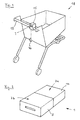
- Fig. 1 In the receiving device 15 is a deposit lock unit 1. On the receiving device 15 or the trolley 18 is a flexibly arranged coupling member 16. The coupling member 16 is used in the deposit lock unit 1 introduced and locked there. By inserting a deposit in the pawn lock unit 1, the previously coupled coupling part 16 is released, so that the transport carriage 18 is usable. After its use, the coupling member 16 is again inserted and locked in the pawn lock unit 1 of another transport carriage 18, so that the previously paid deposit is returned.
- Such lending systems are known for their use in self-service markets.
- Fig. 2 shows a consisting of a coupling mechanism 11 and a deposit retaining device 8 deposit lock unit 1.
- the coupling mechanism 11, which serves to receive the coupling part 16 of another trolley 18 and the deposit for holding a deposit (coin, check card and the like) determined deposit retention device 8 are in a known manner in mutual active connection, cf. also Fig. 4 , This operative connection allows in an alternating sequence the release of the coupling member 16 by entering and retaining a pledge in and by the deposit retention device 8 and vice versa, the release of the pledge when a coupling member 16 inserted into the coupling mechanism 11 of the deposit lock unit 1 becomes.
- the coupling mechanism 11 and the deposit retention device 8 are designed as housed in a respective housing 2a, 2b units. Both units are cassette-like, preferably cuboid shaped and can be combined to form a deposit lock unit 1.
- FIG. 3 In a plan view shows Fig. 3 a receiving device 15 intended for attachment to a transport carriage 18 into which a deposit lock unit 1 is inserted.
- the pawn lock unit 1 in turn consists of a coupling mechanism 11 and a deposit retaining device 8, wherein both are each housed in a separate housing 2a, 2b.
- breakthroughs are provided in a known manner, through which a pledge or a coupling member 16 can be passed.
- FIG. 4 In spatial view shows Fig. 4 a coupling mechanism 11 and a deposit retention device 8 as described above.
- the drawing shows the moment of joining of coupling mechanism 11 and deposit retention device 8 to a deposit lock unit 1.
- the aforementioned operative connection between the coupling mechanism 11 and the deposit retention device 8 is prepared, for example, characterized in that at least one of the coupling mechanism 11 belonging active part 10 by a in the housing 2b of the deposit retention device 8 located opening 9 is passed and cooperates with the deposit retention device 8.
- an active part 10 can also be guided by the deposit-retaining device 8 through an opening 13 in the housing 2a of the coupling mechanism 11 to the coupling mechanism 11.
- FIGS. 2 to 4 show that any replacement of not only the coupling mechanism 11 against another coupling mechanism 11, but also an exchange of the deposit-retaining device 8 is possible against another deposit-retaining device 8.
- the latter is useful, for example, if you want to change the Ffandschiki 8 to another coin system, eg DM to Euro.
Landscapes
- Physics & Mathematics (AREA)
- General Physics & Mathematics (AREA)
- Handcart (AREA)
- Control Of Vending Devices And Auxiliary Devices For Vending Devices (AREA)
Description
- Die Erfindung betrifft zum Einsetzen in die Aufnahmeeinrichtungen von Transportwagen bestimmte, unterschiedlich wirkende Pfandschlosseinheiten, die auf Pfandbasis und mit Hilfe von Kopplungsteilen an die jeweils passende Pfandschlosseinheit eines weiteren Transportwagens ankoppelbar und von dieser wieder lösbar sind, wobei jede Pfandschlosseinheit eine Kopplungsmechanik und eine Pfandrückhalteeinrichtung aufweist, die in gegenseitiger Wirkverbindung stehen.
- Die
DE 42 00 861 C2 beschreibt eine Einrichtung zum Einkaufen von Ware in Selbstbedienungsgeschäften. Bei dieser Einrichtung finden Pfandschlosseinheiten Verwendung, die in verschiedene Gruppen jeweils gleicher Pfandschlosseinheiten aufgeteilt an Transportwagen angeordnet sind. Die Pfandschlosseinheiten oder die Transportwagen sind zum Beispiels pro Gruppe farblich unterschiedlich gekennzeichnet, so dass nur jeweils gleichfarbige Transportwagen gegenseitig an- und abkoppelbar sind. Diese Maßnahmen bewirken, dass an Sammelstellen für Transportwagen keine überlangen Reihen von Transportwagen entstehen, die z.B. störend in die Zufahrtswege von Autos ragen können.
Die Unterschiedlichkeit der in derDE 42 00 861 C2 auch zeichnerisch dargestellten Pfandschlosseinheiten wird dadurch erzielt, dass jede Pfandschlosseinheit eine Anzahl Kammern aufweist, in welche jeweils ein Einlegeteil in eine vorbestimmte Kammer eingelegt werden muss. Entsprechend der jeweiligen Anordnung der Einlegeteile sind die Kopplungsteile dieser Pfandschlosseinheiten unterschiedlich so gestaltet, dass nur Kopplungsteile bestimmter Ausgestaltung mit den entsprechend angeordneten Einlegeteilen korrespondieren können. Ein entscheidender Nachteil dieser technischen Lösung besteht darin, dass die Einlegeteile beim Herstellen der unterschiedlichen Pfandschlosseinheiten in eine falsche Kammer eingelegt werden können, so dass solche Pfandschlosseinheiten nicht mit den für sie bestimmten Kopplungsteilen zusammenwirken. - In der
DE 40 23 396 A1 ist eine als Sicherheitseinrichtung bezeichnete Pfandschlosseinheit beschrieben, die eine gehäuseartige Aufnahmeeinrichtung mit daran angeordneter Befestigungseinrichtung beschreibt. Die Kopplungsmechanik und die Pfandrückhalteeinrichtung sind dabei durch Einzelteile gebildet, die in zeitraubender Weise in die Aufnahmeeinrichtung einzeln eingesetzt werden müssen. Dieser Umstand hat zu einer Weiterentwicklung dieser Pfandschlosseinheit derart geführt, dass nunmehr Teile der Kopplungsmechanik und der Pfandrückhalteeinrichtung in je einem Gehäuse untergebracht sind, wobei das Gehäuse der Pfandrückhalteeinrichtung vom Gehäuse der Kopplungsmechanik aufgenommen ist und die so gebildete Baugruppe in die Aufnahmeeinrichtung eingesetzt ist. - Es ist Aufgabe der Erfindung, eine Pfandschlosseinheit der hier vorliegenden Art so weiterzuentwickeln, dass diese bei einer Einrichtung der eben beschriebenen Art (
DE 42 00 861 C2 ) verwendbar ist. Die Pfandschlosseinheit soll dabei so gestaltet sein, dass ein falsches Anordnen des zur Bildung unterschiedlicher Pfandschlosseinheiten erforderlichen Mittels ausgeschlossen ist. - Die Lösung der Aufgabe besteht darin, dass jede Kopplungsmechanik als eine in einem Gehäuse untergebrachte Baueinheit und jede Pfandrückhalteeinrichtung als eine in einem weiteren Gehäuse untergebrachte Baueinheit gestaltet und in der Aufnahmeeinrichtung benachbart angeordnet sind, wobei sich die Pfandschlosseinheiten durch unterschiedlich wirkende Kopplungsmechaniken unterscheiden.
- Der entscheidende Vorteil der Erfindung besteht darin, dass die jeweils vorgesehene Kopplungseinrichtung in der Aufnahmeeinrichtung der Pfandschlosseinheit platzsparend an die dort befindliche Pfandrückhalteeinrichtung passgenau angesetzt werden kann. Es gibt nur eine Stelle, an welcher die ausgewählte Kopplungsmechanik angeordnet werden kann. Ein falsches Anordnen des als Kopplungsmechanik gestalteten Mittels ist dadurch ausgeschlossen.
- Durch die vorgeschlagene Trennung von Kopplungsmechanik und Pfandrückhalteeinrichtung ist es in vorteilhafter Weise möglich, unterschiedliche Pfandschlosseinheiten durch bloßes Austauschen der Kopplungsmechaniken herzustellen, während die Pfandrückhalteeinrichtungen immer gleich bleiben. So ist zum Beispiel eine Pfandschlosseinheit A mit einer Kopplungsmechanik A, eine Pfandschlosseinheit B mit einer Kopplungseinheit B und eine Pfandschlosseinheit C mit einer Kopplungseinheit C usw. ausgestattet. Die Steckteile für die Pfandschlosseinheiten sind dabei jeweils passend ausgebildet, so dass nur mit Pfandschlosseinheiten A ausgestattete Transportwagen gegenseitig an- und abkoppelbar sind. Gleiches gilt für die Transportwagen mit Pfandschlosseinheiten B und so weiter.
Die Gehäuse für die Kopplungsmechanik und für die Pfandrückhalteeinrichtung sind bevorzugt quaderförmig gestaltet, so dass die Kopplungsmechanik in einer Aufnahmeeinrichtung platzsparend an eine dort befindliche Pfandrückhalteeinrichtung passgenau angesetzt werden kann. Es ist auch möglich, die erwähnten Gehäuse so auszubilden, dass die Kopplungsmechanik und die Pfandrückhalteeinrichtung ineinander steckbar sind. - Die Erfindung wird anhand von Ausführungsbeispielen näher erläutert. Es zeigt
-
Fig. 1 einen Transportwagen mit einer Aufnahmeeinrichtung und Pfandschlosseinheit; -
Fig. 2 eine Pfandschlosseinheit; -
Fig. 3 eine in einer Aufnahmeeinrichtung eingesetzte Pfandschlosseinheit sowie -
Fig. 4 eine Kopplungsmechanik und eine Pfandrückhalteeinrichtung. -
Fig. 1 zeigt einen als Einkaufswagen gestalteten Transportwagen 18. Dessen Schiebegriff 19 trägt eine gehäuseartige Aufnahmeeinrichtung 15. In der Aufnahmeeinrichtung 15 befindet sich eine Pfandschlosseinheit 1. An der Aufnahmeeinrichtung 15 oder am Transportwagen 18 befindet sich ein flexibel angeordnetes Kopplungsteil 16. Das Kopplungsteil 16 dient dazu, in die Pfandschlosseinheit 1 eingeführt und dort verriegelt zu werden. Durch Einführen eines Pfandes in die Pfandschlosseinheit 1 wird das zuvor angekoppelte Kopplungsteil 16 freigegeben, so dass der Transportwagen 18 benutzbar ist. Nach dessen Benutzung wird das Kopplungsteil 16 erneut in die Pfandschlosseinheit 1 eines weiteren Transportwagens 18 eingeführt und verriegelt, so dass das zuvor entrichtete Pfand wieder zurückgegeben wird. Derartige Ausleihsysteme sind durch ihren Einsatz in Selbstbedienungsmärkten bekannt. -
Fig. 2 zeigt eine aus einer Kopplungsmechanik 11 und aus einer Pfandrückhalteeinrichtung 8 bestehende Pfandschlosseinheit 1. Die Kopplungsmechanik 11, die zur Aufnahme des Kopplungsteiles 16 eines weiteren Transportwagens 18 dient und die zur Aufnahme eines Pfandes (Münze, Scheckkarte und dergleichen) bestimmte Pfandrückhalteeinrichtung 8 stehen in bekannter Weise in gegenseitiger Wirkverbindung, vgl. auchFig. 4 . Diese Wirkverbindung ermöglicht in wechselnder Folge das Lösen des Kopplungsteiles 16 durch Eingabe und Zurückhalten eines Pfandes in und durch die Pfandrückhalteeinrichtung 8 und umgekehrt die Herausgabe des Pfandes, wenn ein Kopplungsteil 16 in die Kopplungsmechanik 11 der Pfandschlosseinheit 1 eingeführt wird. Die Kopplungsmechanik 11 und die Pfandrückhalteeinrichtung 8 sind als in je einem Gehäuse 2a, 2b untergebrachte Baueinheiten gestaltet. Beide Baueinheiten sind kassettenartig, bevorzugt quaderförmig gestaltet und lassen sich zu einer Pfandschlosseinheit 1 zusammenfügen. - In einer Draufsicht zeigt
Fig. 3 eine zum Anbau an einen Transportwagen 18 bestimmte Aufnahmeeinrichtung 15 in die eine Pfandschlosseinheit 1 eingesetzt ist. Die Pfandschlosseinheit 1 besteht wiederum aus einer Kopplungsmechanik 11 und aus einer Pfandrückhalteeinrichtung 8, wobei beide in je einem eigenen, separaten Gehäuse 2a, 2b untergebracht sind. An der Aufnahmeeinrichtung 15 sind in bekannter Weise nicht näher dargestellte Durchbrüche vorgesehen, durch welche ein Pfand beziehungsweise ein Kopplungsteil 16 hindurchgeführt werden können. - In räumlicher Ansicht zeigt
Fig. 4 eine Kopplungsmechanik 11 und eine Pfandrückhalteeinrichtung 8 wie vorab beschrieben. Die Zeichnung zeigt den Augenblick des Zusammenfügens von Kopplungsmechanik 11 und Pfandrückhalteeinrichtung 8 zu einer Pfandschlosseinheit 1. Die erwähnte Wirkverbindung zwischen der Kopplungsmechanik 11 und der Pfandrückhalteeinrichtung 8 wird z.B. dadurch hergestellt, daß wenigstens ein der Kopplungsmechanik 11 angehörendes Wirkteil 10 durch eine im Gehäuse 2b der Pfandrückhalteeinrichtung 8 befindliche Öffnung 9 hindurchgeführt ist und mit der Pfandrückhalteeinrichtung 8 zusammenwirkt. Ein derartiges Wirkteil 10 kann umgekehrt auch von der Pfandrückhalteeinrichtung 8 durch eine im Gehäuse 2a der Kopplungsmechanik 11 befindliche Öffnung 13 zur Kopplungsmechanik 11 geführt sein. Es ist zweckmäßig, eine exakte Anordnung der Kopplungsmechanik 11 und der Pfandrückhalteeinrichtung 8 nicht nur der Aufnahmeeinrichtung 15 zu überlassen, sondern zumindest einen Formschluß zwischen dem Gehäuse 2b der Kopplungsmechanik und dem Gehäuse 2a der Pfandrückhalteeinrichtung 8 herzustellen. Ein solcher Formschluss kann durch gegenseitig korrespondierende Konturen, z.B. Vertiefungen, Erhöhungen, Zapfen, Löcher usw., die sich an den gemeinsamen Auflageflächen 2c des Gehäuses 2b der Kopplungsmechanik 11 und des Gehäuses 2a der Pfandrückhalteeinrichtung 8 befinden, hergestellt werden. Darüber hinaus sind auch schnappschlüssige Verbindungen möglich. Eine weitere Führungsfunktion beim Zusammenfügen der Gehäuse 2a und 2b kann auch dem Wirkteil 10 übertragen werden. - Die in den
Figuren 2 bis 4 gezeigten Ausführungsbeispiele zeigen, dass ein beliebiges Austauschen nicht nur der Kopplungsmechanik 11 gegen eine andere Kopplungsmechanik 11, sondern auch ein Austausch der Pfandrückhalteeinrichtung 8 gegen eine weitere Pfandrückhalteeinrichtung 8 möglich ist. Letzteres ist zum Beispiel zweckmäßig, wenn man die Ffandschlosseinheit 8 auf ein anderes Münzsystem, z.B. DM auf Euro, umstellen will.
Claims (5)
- Zum Einsetzen in die Aufnahmeeinrichtung (15) von Transportwagen (18) bestimmte, unterschiedlich wirkende Pfandschlosseinheiten (1), die auf Pfandbasis und mit Hilfe von Kopplungsteilen (16) an die jeweils passende Pfandschlosseinheit (1) eines weiteren Transportwagens (18) ankoppelbar und von dieser wieder lösbar sind, wobei jede Pfandschlosseinheit (1) eine Kopplungsmechanik (11) und eine Pfandrückhalteeinrichtung (8) aufweist, die in gegenseitiger Wirkverbindung stehen, dadurch gekennzeichnet, dass jede Kopplungsmechanik (11) als eine in einem Gehäuse (2a) untergebrachte Baueinheit und jede Pfandrückhalteeinrichtung (8) als eine in einem weiteren Gehäuse (2b) untergebrachte Baueinheit gestaltet und in der Aufnahmeeinrichtung (15) benachbart angeordnet sind, wobei sich die Pfandschlosseinheiten (1) durch unterschiedlich wirkende Kopplungsmechaniken (11) unterscheiden.
- Pfandschlosseinheiten nach Anspruch 1, dadurch gekennzeichnet, dass die Wirkverbindung zwischen jeder Kopplungsmechanik (11) und jeder Pfandrückhalteeinrichtung (8) durch wenigstens ein Wirkteil (10) gebildet ist, das die Kopplungsmechanik (11) mit der Pfandrückhalteeinrichtung (8) verbindet.
- Pfandschlosseinheiten nach Anspruch 1 oder 2, dadurch gekennzeichnet, dass an den gemeinsamen Anlageflächen (2c) der Gehäuse (2a, 2b) gegenseitig korrespondierende, zumindest einen Formschluss zwischen dem Gehäuse (2a) und dem Gehäuse (2b) herstellende Konturen vorgesehen sind.
- Pfandschlosseinheiten nach einem der Ansprüche 1 bis 3, dadurch gekennzeichnet, dass das Gehäuse (2a) mit dem Gehäuse (2b) schnappschlüssig verbunden ist.
- Pfandschlosseinheiten nach einem der Ansprüche 1 bis 4, dadurch gekennzeichnet, dass das wenigstens eine Wirkteil (10) zur Ausübung einer Führungsfunktion beim Zusammenfügen der Gehäuse (2a) und (2b) bestimmt ist.
Applications Claiming Priority (2)
| Application Number | Priority Date | Filing Date | Title |
|---|---|---|---|
| DE19750059 | 1997-11-12 | ||
| DE19750059A DE19750059A1 (de) | 1997-11-12 | 1997-11-12 | Pfandschloßeinheit |
Publications (3)
| Publication Number | Publication Date |
|---|---|
| EP0917115A1 EP0917115A1 (de) | 1999-05-19 |
| EP0917115B1 EP0917115B1 (de) | 2002-01-16 |
| EP0917115B2 true EP0917115B2 (de) | 2008-11-19 |
Family
ID=7848452
Family Applications (1)
| Application Number | Title | Priority Date | Filing Date |
|---|---|---|---|
| EP98120300A Expired - Lifetime EP0917115B2 (de) | 1997-11-12 | 1998-10-27 | Pfandschlosseinheit |
Country Status (2)
| Country | Link |
|---|---|
| EP (1) | EP0917115B2 (de) |
| DE (2) | DE19750059A1 (de) |
Cited By (1)
| Publication number | Priority date | Publication date | Assignee | Title |
|---|---|---|---|---|
| CN112141196A (zh) * | 2020-09-03 | 2020-12-29 | 重庆工商大学 | 一种智能超市用的购物车排队装置 |
Families Citing this family (4)
| Publication number | Priority date | Publication date | Assignee | Title |
|---|---|---|---|---|
| DE19743649A1 (de) * | 1997-10-02 | 1999-04-08 | Wanzl Metallwarenfabrik Kg | Halterung mit einem Raum zur Aufnahme einer Pfandschloßvorrichtung |
| EP1485888A2 (de) * | 2002-03-13 | 2004-12-15 | Franz Wieth | Pfandschloss f r einen transportwagen |
| GB2441125A (en) * | 2006-08-25 | 2008-02-27 | Maurice Hawley | Door trolley |
| ES2742880T3 (es) | 2012-06-15 | 2020-02-17 | Canon Kk | Cartucho, cartucho de proceso y dispositivo de formación de imágenes electrofotográficas |
Citations (1)
| Publication number | Priority date | Publication date | Assignee | Title |
|---|---|---|---|---|
| DE4023396A1 (de) † | 1990-07-23 | 1992-01-30 | Systec Ausbausysteme Gmbh | Sicherungseinrichtung fuer transportwagen |
Family Cites Families (3)
| Publication number | Priority date | Publication date | Assignee | Title |
|---|---|---|---|---|
| EP0537404B1 (de) | 1991-10-14 | 1996-04-10 | Vendoret Holding S.A. | Schiebegriffvorrichtung für Einkaufswagen |
| DE4200861C2 (de) | 1992-01-15 | 1996-07-25 | Wolfgang Eberlein | Einrichtung zum Einkaufen von Ware in einem Selbstbedienungsgeschäft oder zum Transport von Reisegepäck |
| DE9315684U1 (de) * | 1993-10-14 | 1993-12-02 | Wanzl Metallwarenfabrik Gmbh, 89340 Leipheim | Pfandschloß für einen Transportwagen |
-
1997
- 1997-11-12 DE DE19750059A patent/DE19750059A1/de not_active Withdrawn
-
1998
- 1998-10-27 EP EP98120300A patent/EP0917115B2/de not_active Expired - Lifetime
- 1998-10-27 DE DE59802623T patent/DE59802623D1/de not_active Expired - Fee Related
Patent Citations (1)
| Publication number | Priority date | Publication date | Assignee | Title |
|---|---|---|---|---|
| DE4023396A1 (de) † | 1990-07-23 | 1992-01-30 | Systec Ausbausysteme Gmbh | Sicherungseinrichtung fuer transportwagen |
Non-Patent Citations (2)
| Title |
|---|
| "Prospekt "systec Pos-Technology GmbH", "Duraloc", "Austausch der Muenzkassette" in deutscher Sprache", 1996 † |
| "Prospekt "systec Pos-Technology GmbH", "Duraloc", "Austausch der Muenzkassette" in englischer Sprache", 1996 † |
Cited By (1)
| Publication number | Priority date | Publication date | Assignee | Title |
|---|---|---|---|---|
| CN112141196A (zh) * | 2020-09-03 | 2020-12-29 | 重庆工商大学 | 一种智能超市用的购物车排队装置 |
Also Published As
| Publication number | Publication date |
|---|---|
| EP0917115B1 (de) | 2002-01-16 |
| EP0917115A1 (de) | 1999-05-19 |
| DE19750059A1 (de) | 1999-05-20 |
| DE59802623D1 (de) | 2002-02-21 |
Similar Documents
| Publication | Publication Date | Title |
|---|---|---|
| EP0070997B1 (de) | Einrichtung zum Sicherstellen einer ordnungsgemässen Rückgabe von ausgeliehenen Einkaufswagen | |
| DE2900367C2 (de) | ||
| DE3152579C2 (de) | ||
| DE102013111478A1 (de) | Halterung für ein mobiles Telekommunikationsendgerät | |
| EP0917115B2 (de) | Pfandschlosseinheit | |
| DE3730813C1 (de) | Bandkassettengehaeuse mit Kopplungselementen | |
| DE4200861C2 (de) | Einrichtung zum Einkaufen von Ware in einem Selbstbedienungsgeschäft oder zum Transport von Reisegepäck | |
| EP0894313B1 (de) | Einrichtung zum einkaufen von ware oder zum transport von gepäck | |
| DE29612174U1 (de) | Einrichtung zum Einkaufen von Ware in einem Selbstbedienungsgeschäft oder zum Transport von Reisegepäck | |
| DE29606902U1 (de) | Behälter zur Aufnahme von Münzen und Identifikationskarten | |
| DE19750058B4 (de) | Pfandschloßeinheit | |
| WO2004049272A1 (de) | Magazin zum bereitstellen von transportwagen | |
| WO2000005682A1 (de) | Maschinenlesbare ausweiskarte | |
| EP0907153A2 (de) | Halterung mit einem Raum zur Aufnahme einer Pfandschlossvorrichtung | |
| EP2560148B1 (de) | Vorrichtung zum Befestigen von Peripheriegeräten an automatischen Kassensystemen | |
| DE3932593C2 (de) | Informationsträgerrahmen für Warenkörbe | |
| DE69800189T2 (de) | Datenübertragungsvorrichtung | |
| DE9114589U1 (de) | Schlüsselanhänger | |
| DE19722609A1 (de) | Ordnungssystem für Einkaufswagen | |
| AT502517B1 (de) | Handwagen | |
| DE202025106392U1 (de) | Dienstausweis | |
| DE948454C (de) | Einrichtung fuer Wertzeichendrucker, insbesondere Fahrkartendrucker, mit auswechselbaren Druckstoecken | |
| EP0945832A2 (de) | Einrichtung zum Ausleihen von Transportwagen | |
| DE19735297C2 (de) | Lernspielvorrichtung | |
| DE19719460A1 (de) | Ordnungssystem für Einkaufswagen |
Legal Events
| Date | Code | Title | Description |
|---|---|---|---|
| PUAI | Public reference made under article 153(3) epc to a published international application that has entered the european phase |
Free format text: ORIGINAL CODE: 0009012 |
|
| AK | Designated contracting states |
Kind code of ref document: A1 Designated state(s): DE ES FR GB IT |
|
| AX | Request for extension of the european patent |
Free format text: AL;LT;LV;MK;RO;SI |
|
| 17P | Request for examination filed |
Effective date: 19990728 |
|
| AKX | Designation fees paid |
Free format text: DE ES FR GB IT |
|
| GRAG | Despatch of communication of intention to grant |
Free format text: ORIGINAL CODE: EPIDOS AGRA |
|
| 17Q | First examination report despatched |
Effective date: 20010219 |
|
| GRAG | Despatch of communication of intention to grant |
Free format text: ORIGINAL CODE: EPIDOS AGRA |
|
| GRAG | Despatch of communication of intention to grant |
Free format text: ORIGINAL CODE: EPIDOS AGRA |
|
| GRAH | Despatch of communication of intention to grant a patent |
Free format text: ORIGINAL CODE: EPIDOS IGRA |
|
| GRAH | Despatch of communication of intention to grant a patent |
Free format text: ORIGINAL CODE: EPIDOS IGRA |
|
| GRAA | (expected) grant |
Free format text: ORIGINAL CODE: 0009210 |
|
| REG | Reference to a national code |
Ref country code: GB Ref legal event code: IF02 |
|
| AK | Designated contracting states |
Kind code of ref document: B1 Designated state(s): DE ES FR GB IT |
|
| PG25 | Lapsed in a contracting state [announced via postgrant information from national office to epo] |
Ref country code: IT Free format text: LAPSE BECAUSE OF FAILURE TO SUBMIT A TRANSLATION OF THE DESCRIPTION OR TO PAY THE FEE WITHIN THE PRE;WARNING: LAPSES OF ITALIAN PATENTS WITH EFFECTIVE DATE BEFORE 2007 MAY HAVE OCCURRED AT ANY TIME BEFORE 2007. THE CORRECT EFFECTIVE DATE MAY BE DIFFERENT FROM THE ONE RECORDED.SCRIBED TIME-LIMIT Effective date: 20020116 Ref country code: GB Free format text: LAPSE BECAUSE OF FAILURE TO SUBMIT A TRANSLATION OF THE DESCRIPTION OR TO PAY THE FEE WITHIN THE PRESCRIBED TIME-LIMIT Effective date: 20020116 |
|
| REF | Corresponds to: |
Ref document number: 59802623 Country of ref document: DE Date of ref document: 20020221 |
|
| GBV | Gb: ep patent (uk) treated as always having been void in accordance with gb section 77(7)/1977 [no translation filed] |
Effective date: 20020116 |
|
| PG25 | Lapsed in a contracting state [announced via postgrant information from national office to epo] |
Ref country code: ES Free format text: LAPSE BECAUSE OF FAILURE TO SUBMIT A TRANSLATION OF THE DESCRIPTION OR TO PAY THE FEE WITHIN THE PRESCRIBED TIME-LIMIT Effective date: 20020730 |
|
| PLBI | Opposition filed |
Free format text: ORIGINAL CODE: 0009260 |
|
| PLBF | Reply of patent proprietor to notice(s) of opposition |
Free format text: ORIGINAL CODE: EPIDOS OBSO |
|
| 26 | Opposition filed |
Opponent name: SYSTEC POS-TECHNOLOGY GMBH Effective date: 20021016 |
|
| PLBF | Reply of patent proprietor to notice(s) of opposition |
Free format text: ORIGINAL CODE: EPIDOS OBSO |
|
| PLAY | Examination report in opposition despatched + time limit |
Free format text: ORIGINAL CODE: EPIDOSNORE2 |
|
| PLAT | Information related to reply to examination report in opposition deleted |
Free format text: ORIGINAL CODE: EPIDOSDORE3 |
|
| PLBC | Reply to examination report in opposition received |
Free format text: ORIGINAL CODE: EPIDOSNORE3 |
|
| PLBC | Reply to examination report in opposition received |
Free format text: ORIGINAL CODE: EPIDOSNORE3 |
|
| APBP | Date of receipt of notice of appeal recorded |
Free format text: ORIGINAL CODE: EPIDOSNNOA2O |
|
| APAH | Appeal reference modified |
Free format text: ORIGINAL CODE: EPIDOSCREFNO |
|
| APAH | Appeal reference modified |
Free format text: ORIGINAL CODE: EPIDOSCREFNO |
|
| APBQ | Date of receipt of statement of grounds of appeal recorded |
Free format text: ORIGINAL CODE: EPIDOSNNOA3O |
|
| APBU | Appeal procedure closed |
Free format text: ORIGINAL CODE: EPIDOSNNOA9O |
|
| PGFP | Annual fee paid to national office [announced via postgrant information from national office to epo] |
Ref country code: DE Payment date: 20071031 Year of fee payment: 10 |
|
| PUAH | Patent maintained in amended form |
Free format text: ORIGINAL CODE: 0009272 |
|
| STAA | Information on the status of an ep patent application or granted ep patent |
Free format text: STATUS: PATENT MAINTAINED AS AMENDED |
|
| 27A | Patent maintained in amended form |
Effective date: 20081119 |
|
| AK | Designated contracting states |
Kind code of ref document: B2 Designated state(s): DE ES FR GB IT |
|
| REG | Reference to a national code |
Ref country code: ES Ref legal event code: FD2A Effective date: 20021028 |
|
| PGFP | Annual fee paid to national office [announced via postgrant information from national office to epo] |
Ref country code: FR Payment date: 20081021 Year of fee payment: 11 |
|
| PG25 | Lapsed in a contracting state [announced via postgrant information from national office to epo] |
Ref country code: DE Free format text: LAPSE BECAUSE OF NON-PAYMENT OF DUE FEES Effective date: 20090501 |
|
| REG | Reference to a national code |
Ref country code: FR Ref legal event code: ST Effective date: 20110819 |
|
| PG25 | Lapsed in a contracting state [announced via postgrant information from national office to epo] |
Ref country code: FR Free format text: LAPSE BECAUSE OF NON-PAYMENT OF DUE FEES Effective date: 20091102 |