EP0916613B1 - Hülsenvorlageeinrichtung für Kreuzspulen herstellende Textilmaschinen - Google Patents
Hülsenvorlageeinrichtung für Kreuzspulen herstellende Textilmaschinen Download PDFInfo
- Publication number
- EP0916613B1 EP0916613B1 EP98118041A EP98118041A EP0916613B1 EP 0916613 B1 EP0916613 B1 EP 0916613B1 EP 98118041 A EP98118041 A EP 98118041A EP 98118041 A EP98118041 A EP 98118041A EP 0916613 B1 EP0916613 B1 EP 0916613B1
- Authority
- EP
- European Patent Office
- Prior art keywords
- tube
- sleeve
- feeding device
- control
- track
- Prior art date
- Legal status (The legal status is an assumption and is not a legal conclusion. Google has not performed a legal analysis and makes no representation as to the accuracy of the status listed.)
- Expired - Lifetime
Links
- 239000004753 textile Substances 0.000 title claims description 18
- 229910000639 Spring steel Inorganic materials 0.000 claims description 10
- 239000003302 ferromagnetic material Substances 0.000 claims description 5
- 230000002441 reversible effect Effects 0.000 claims description 3
- 238000012544 monitoring process Methods 0.000 claims 1
- 238000004804 winding Methods 0.000 description 23
- 238000003860 storage Methods 0.000 description 14
- 230000005294 ferromagnetic effect Effects 0.000 description 10
- 239000000872 buffer Substances 0.000 description 9
- 238000000034 method Methods 0.000 description 4
- 229910000831 Steel Inorganic materials 0.000 description 2
- 238000012432 intermediate storage Methods 0.000 description 2
- 230000005291 magnetic effect Effects 0.000 description 2
- 239000010959 steel Substances 0.000 description 2
- 230000005540 biological transmission Effects 0.000 description 1
- 230000001419 dependent effect Effects 0.000 description 1
- 230000000694 effects Effects 0.000 description 1
- 238000004519 manufacturing process Methods 0.000 description 1
- 238000007383 open-end spinning Methods 0.000 description 1
- 238000009420 retrofitting Methods 0.000 description 1
- 238000007378 ring spinning Methods 0.000 description 1
- 238000009987 spinning Methods 0.000 description 1
Images


Classifications
-
- B—PERFORMING OPERATIONS; TRANSPORTING
- B65—CONVEYING; PACKING; STORING; HANDLING THIN OR FILAMENTARY MATERIAL
- B65H—HANDLING THIN OR FILAMENTARY MATERIAL, e.g. SHEETS, WEBS, CABLES
- B65H67/00—Replacing or removing cores, receptacles, or completed packages at paying-out, winding, or depositing stations
- B65H67/06—Supplying cores, receptacles, or packages to, or transporting from, winding or depositing stations
- B65H67/068—Supplying or transporting empty cores
-
- B—PERFORMING OPERATIONS; TRANSPORTING
- B65—CONVEYING; PACKING; STORING; HANDLING THIN OR FILAMENTARY MATERIAL
- B65H—HANDLING THIN OR FILAMENTARY MATERIAL, e.g. SHEETS, WEBS, CABLES
- B65H2701/00—Handled material; Storage means
- B65H2701/30—Handled filamentary material
- B65H2701/31—Textiles threads or artificial strands of filaments
Definitions
- the invention relates to a sleeve presentation device for Textile machines producing cross-wound bobbins according to the generic term of claim 1.
- a disadvantage of these known devices is, above all, that the package changer positioned at the place of work first wait for the arrival of a requested empty tube got to. The waiting times that occur have a negative effect the overall efficiency of these textile machines.
- the cross-wound bobbin changers of these textile machines have both a handling mechanism for transferring the empty tubes from the tube conveyor belt into the intermediate store and a handling device for receiving and changing the empty tubes deposited in the intermediate stores in the bobbin frame of the relevant winding units.
- a new empty tube is immediately requested by the operating unit at the beginning of the package change process, which transfers the operating unit to the intermediate storage unit of the winding unit before it leaves the winding unit.
- an improved To create sleeve feed means i.e. a Tube feed device, in which the transfer of empty tubes from the central sleeve magazine to the intermediate sleeve stores an alternative way is accomplished.
- the embodiment of the invention has the advantage that the sleeve feed device, which consists essentially of a stationary, horizontal, window-like Recessing path, one along this path slidably mounted, also window-like recesses possessing control band as well as a movable on the train Sleeve transport trolley exists, both the horizontal running web as well as the control band from one ferromagnetic material, preferably steel are, has only a few, relatively robust components. A such training not only leaves a long life Expect establishment, but also leads to a good one Price / performance ratio of the facility.
- the sleeve feed device according to the invention stands out due to their constructive structure also by a high Functionality and good availability.
- the type of control on the sleeve transport trolley arranged sleeve gripping device has proven to be very proven reliable and almost wear-free.
- the web and the control band have a large number of window-like recesses, the dimensions and spacings of which correspond.
- the positions of the recesses arranged in the stationary path result from the winding position division of the textile machine, this winding position division also determining the division of the storage columns of the central sleeve magazine.
- Such an embodiment makes it possible, in a simple and advantageous manner, to create magnetizable or non-magnetizable zones at any time both in the area of the bobbin-specific buffer stores and in the area of the storage columns of the central sleeve magazine, which zones in connection with a corresponding permanent magnet package arrangement arranged on the sleeve transport carriage for a control process of the sleeve gripping device this means of transport can be used. That is, by appropriately positioning the recesses of the control belt slidably mounted along the track, a permanent magnet package arranged on the sleeve transport carriage can be activated if necessary, and the sleeve gripping device of the sleeve transport carriage can thus be actuated reliably and quickly.
- the control belt is, as described in claim 2, connected to a thrust piston gear, which, as usual, has two defined end positions.
- the end positions of the thrust piston transmission each correspond to a first or second control position of the control belt. In connection with the positioning of the control band, no further additional control devices are therefore necessary.
- the control band is preferably positioned in its first control position with respect to the stationary path such that, as stated in claim 3, the window-like recesses of the control band are arranged congruently with the corresponding recesses of the horizontally running path.
- the recesses of the web and the recesses of the control belt are in the middle of the storage columns of the central sleeve magazine or in the middle of the winding station's own intermediate buffers. This means that in the first control position of the control band, these areas are always free of ferromagnetic material, so that there is a non-magnetizable zone.
- the second control position which is described in claim 4, leads to a continuous ferromagnetic zone in the Area of the horizontal path, since the control band in axially shifted this control position relative to the web is that all the recesses of the web through the control band be completely covered.
- a high resolution Sensor device for example an incremental encoder, has, the sleeve transport carriage on the one hand with high Speed the sleeve receiving positions in the range of central sleeve magazine and / or the sleeve delivery positions move to the winding unit's own sleeve buffers and on the other hand, it is always very quick and very precise be positioned.
- Sleeve gripping device of the sleeve transport carriage from two swiveling gripper arms For example, as two-armed gripper arms formed sleeve handling elements are coupled via a spring steel strip in such a way that the Gripper arms in an unloaded spring steel band in one so-called sleeve receiving position.
- the gripper arms are also in the sense of spring elements "Open" applied (claim 9).
- a permanent magnet package is fixed to the spring steel band, which can be used in conjunction with a ferromagnetic counter pole to deflect the spring steel band and thus to close the sleeve gripping device.
- the endeavor of the permanent magnet package is always to a magnetizable opposite pole, for. B. to use the ferromagnetic track or the ferromagnetic control band, exploited.
- the dimensioning of the spring steel strip connected between the gripper arms and its distance from the horizontally running path is advantageously chosen so that a direct application of the permanent magnet package to the ferromagnetic opposite pole is reliably avoided.
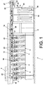
- FIG. 1 a front view of a winder generally identified with the reference number 1 is shown schematically.
- Such winding machines 1 usually have a large number of similar winding stations 4 between their machine end frames 2 and 3.
- the spinning bobbins 22 produced on a ring spinning machine (not shown) are rewound to form large-volume cross-wound bobbins 5.
- the finished cross-wound bobbins 5 are pushed out by means of an automatically operating operating device, for example by means of a cross-wound bobbin changer 6, onto a cross-wound bobbin conveyor belt 7 and transported to a bobbin loading device or the like arranged on the machine end (not shown).
- the one arranged above the work stations 4 so as to be movable Cross-coil changer 6 not only ensures that the on the winding units 4 finished packages 5 on the Cross coil conveyor belt 7 are pushed out, but he also automatically changes a sleeve 8 in each Coil frame of the relevant winding unit 4.
- a total of 11 designated central sleeve magazine consists essentially of a central unit 50, with the central magazine Control device 30 and a vertically movable Gripper slide 16 and one on the central unit 50 removable storage unit 51.
- the Storage unit 51 has several, side by side arranged storage columns 12, 13, 14, 15, which in turn a number of one above the other Series of sleeves, so-called loading chutes, for have conical and / or cylindrical empty sleeves 8.
- the central sleeve magazine 11 is above the vertically movable Gripper slide 16, which, as indicated in Fig. 2, in the area each of the storage columns 12-15 defines one controllable sleeve gripper 17, functional with the Sleeve transport device 10 connected.
- the sleeve transport device 10 consists essentially of a horizontal path 18, one along the path 18 axially displaceable control band 19 and one on the Track 18 movably arranged sleeve transport carriage 20.
- the U-shaped path 18 is made of one ferromagnetic material, for example steel, manufactured and has a plurality of window-like recesses 23.
- the Recesses 23 are each centered on the winding units 4 the winding machine 1 and thus in the center of those arranged there Sleeve buffers 9 and in the middle of the Storage columns 12 - 15 of the central sleeve magazine 11 arranged.
- the control band 19, which is also made of a ferromagnetic Material is made, has similar window-like Recesses 24 on the dimensions of the recesses 23 correspond to track 18.
- the recesses 23, 24 have the same mutual distances. Are preferred the recesses 24 of the control band 19 also from Accident protection reasons, with a grid-like finger protection Mistake.
- the control band 19, which via guide devices 36 is slidably mounted on the track 18 can by a Thrust piston gear 25 between a control position A and a control position B (shown in FIGS. 6 and 7) be moved.
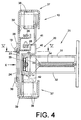
- the connection of the Sleeve transport carriage 20 to the endless traction means 26 thereby via one on the chassis 40 of the sleeve transport carriage 20 arranged connection console 41.
- On the chassis 40 is also a pincer-like sleeve gripping device 21, whose Gripper arms 31, 32 can be pivoted to a limited extent in pivot axes 42 are stored.
- the preferably angled gripper arms 31, 32 are over a Spring steel strip 33 to which a permanent magnet package 35 is attached is connected.
- the gripper arms 31, 32 each spring elements 34 articulated, the gripper arms 31, 32nd act in the sense of "open".
- the winding machine 1 is in an operational state.
- the storage columns 12-15 of the central sleeve magazine 11 are filled with empty sleeves 8.
- the control device 30 is set in accordance with the desired loading program via the input keyboard 43 of the central sleeve magazine 11.
- the sleeve transport carriage 20 then leads first into one 0 position in the area of the electric drive 27 and there by means of a sensor device 29, for example by means of of a high-resolution incremental encoder.
- the gripper carriage 16 moves in the Central unit 50 of the sleeve central magazine 11 the predetermined Sleeve receiving series of the sleeve central magazine 11 (per Storage columns are, for example, eight to ten each Rows of sleeves arranged one above the other).
- One of Sleeve gripper 17 of the gripper carriage 16 takes out of the selected sleeve receiving row an empty tube 8 and passes them to the sleeve gripper device 21 in the meantime above the relevant storage column 12 - 15 des Sleeve central magazine 11 positioned sleeve transport carriage 20th
- the control band 19 is at this time in the Control position A (see Figures 5 and 6), in which the Recesses 23 of the web 18 and the recesses 24 of the Control tape 19 are one above the other. Because of that Sleeve gripping device 21 of the sleeve transport carriage 20 arranged permanent magnet package 35 in the control position A the control band 19 no ferromagnetic counter pole faces, the Permenentmagnetcou35 remains deactivated and the gripper arms 31, 32 by spring elements 34 in the sense "open", remain open. That is, the Sleeve gripping device 21 of the sleeve transport carriage 20 is in the tax position A of the tax band ready for takeover an empty tube 8.
- the control belt 19 in the control position B (see Figure 7) shifted. That means, the control band 19 is axially displaced until the Recesses 23 in the path 18 through the ferromagnetic Control band 19 are completely closed.
- Closing the recesses 23 of the web 18 results in a continuously ferromagnetic, that is to say magnet-activating, zone in the region of the web 18.
- the permanent magnet package 35 of the sleeve transport carriage 20 immediately tries to contact this ferromagnetic opposite pole, so that under the magnetic force of the permanent magnet package 35 the spring steel strip 33 is laid out in the R direction and the gripper arms 31, 32 are pivoted in the S direction.
- the gripper arms 31, 32 pivoting in the direction S fix the empty sleeve 8 between them.
- the tube transport carriage 20 is then immediately conveyed at high speed to the tube buffer 9 of the selected winding unit 4 and positioned there exactly above the tube buffer 9. Subsequently, the control belt 19 is switched back to the control position A, that is, the zone in front of the permanent magnet package 35 of the sleeve transport carriage 20 is made non-magnetizable. The permanent magnet package 35 thereby loses its ferromagnetic opposite pole, so that the gripper arms 31, 32 are pivoted back into a sleeve delivery position under the force of the spring elements 34. The sleeve 8 then falls into the intermediate sleeve store 9 of the winding unit 4 in question.
- the sleeve transport carriage 20 now returns immediately to his Starting position back, that is, it moves to its 0 position in Area of the electric drive 27.
- the newly adjusted Sleeve transport trolley 20 then stands for the next one Sleeve transport process ready.
Landscapes
- Replacing, Conveying, And Pick-Finding For Filamentary Materials (AREA)
- Spinning Or Twisting Of Yarns (AREA)
Description
Bei diesen bekannten Einrichtungen wird zu Beginn des Kreuzspulenwechselvorganges durch das Bedienaggregat sofort eine neue Leerhülse angefordert, die das Bedienaggregat, bevor es die Spulstelle wieder verläßt, in den Zwischenspeicher der Spulstelle überführt.
Eine solche Ausführungsform ermöglicht es auf einfache und vorteilhafte Weise, sowohl im Bereich der spulstelleneigenen Zwischenspeicher als auch im Bereich der Speicherkolumnen des zentralen Hülsenmagazins jederzeit magnetisierbare oder nichtmagnetisierbare Zonen zu schaffen, die in Verbindung mit einer entsprechenden, am Hülsentransportwagen angeordneten Permanentmagnetpaketanordnung für einen Steuerungsvorgang der Hülsengreifeinrichtung dieses Transportmittels benutzt werden können. Das heißt, durch entsprechende Positionierung der Ausnehmungen des entlang der Bahn verschiebbar gelagerten Steuerbandes kann im Bedarfsfall ein am Hülsentransportwagen angeordnetes Permanentmagnetpaket aktiviert und damit die Hülsengreifeinrichtung des Hülsentransportwagens zuverlässig und schnell betätigt werden.
Im Zusammenhang mit der Positionierung des Steuerbandes sind daher keine weiteren zusätzlichen Steuereinrichtungen mehr nötig.
Die Ausnehmungen der Bahn und die Ausnehmungen des Steuerbandes stehen dabei mittig zu den Speicherkolumnen des Hülsenzentralmagazins bzw. mittig zu den spulstelleneigenen Hülsenzwischenspeichern. Das heißt, in der ersten Steuerstellung des Steuerbandes sind diese Bereiche stets frei von ferromagnetischem Werkstoff, so daß dort eine nichtmagnetisierbare Zone gegeben ist.
Die Dimensionierung des zwischen die Greiferarme eingeschalteten Federstahlbandes sowie dessen Abstand zur horizontal verlaufenden Bahn ist dabei vorteilhafterweise so gewählt, daß ein direktes Anlegen des Permanentmagnetpaketes an den ferromagnetischen Gegenpol zuverlässig vermieden wird.
- Fig. 1
- eine Vorderansicht auf eine Kreuzspulen herstellende Textilmaschine, mit einer erfindungsgemäßen Hülsenvorlageeinrichtung,
- Fig. 2
- die Einrichtung gemäß Figur 1, in Draufsicht,
- Fig. 3
- eine Seitenansicht einer Arbeitsstelle, der in den Figuren 1 und 2 dargestellten Textilmaschine,
- Fig. 4
- eine Seitenansicht auf eine horizontal verlaufende Bahn mit einem verschiebbar gelagerten Steuerband sowie einen Hülsentransportwagen, gemäß Schnitt IV-IV der Figur 5,
- Fig. 5
- eine Draufsicht auf einen Hülsentransportwagen, gemäß Schnitt V-V der Figur 4,
- Fig. 6
- die horizontal verlaufende Bahn mit einem in Steuerstellung A positionierten Steuerband, gemäß Blickrichtung X der Fig.4,
- Fig. 7
- die Bahn mit einem in Steuerstellung B positionierten Steuerband, ebenfalls gemäß Blickrichtung X der Fig.4,
Die fertiggestellten Kreuzspulen 5 werden mittels einer selbsttätig arbeitenden Bedienvorrichtung, zum Beispiel mittels eines Kreuzspulenwechslers 6, auf ein Kreuzspulentransportband 7 ausgeschoben und zu einer maschinenendseitig angeordneten (nicht dargestellten) Spulenverladeeinrichtung oder dergleichen transportiert.
Die Speicherkolumnen 12 - 15 des Hülsenzentralmagazins 11 sind mit Leerhülsen 8 gefüllt.
Über die Eingabetastatur 43 des Hülsenzentralmagazins 11 wird die Steuereinrichtung 30 entsprechend dem gewünschten Beschickungsprogramm eingestellt.
Das Permanentmagnetpaket 35 des Hülsentransportwagens 20 versucht sofort sich an diesen ferromagnetischer Gegenpol anzulegen, so daß unter der Magnetkraft des Permanentmagnetpaketes 35 das Federstahlband 33 in Richtung R ausgelegt wird und die Greiferarme 31, 32 in Richtung S verschwenkt werden. Die in Richtung S einschwenkenden Greiferarme 31, 32 fixieren dabei die Leerhülse 8 zwischen sich.
Das Permanetmagnetpaket 35 verliert dadurch seinen ferromagnetischen Gegenpol, so daß die Greiferarme 31, 32 unter der Kraft der Federelemente 34 in eine Hülsenabgabestellung zurückgeschwenkt werden. Die Hülse 8 fällt daraufhin in den Hülsenzwischenspeicher 9 der betreffenden Spulstelle 4.
Claims (10)
- Hülsenvorlageeinrichtung für Kreuzspulen herstellende Textilmaschinen, mit einem maschinenendseitig angeordneten Hülsenzentralmagazin (11), arbeitsstelleneigenen Hülsenzwischenspeichern (9) sowie einer Transporteinrichtung (10) zum Verteilen der Leerhülsen (8) auf die arbeitsstelleneigenen Hülsenzwischenspeicher (9), wobei die Transporteinrichtung (10) über eine maschinenlange, horizontal verlaufende Bahn (18) verfügt,
dadurch gekennzeichnet,daß ein Steuerband (19) entlang der Bahn (18) verschiebbar gelagert ist,daß die Bahn (18) und das Steuerband (19) jeweils mit einer Vielzahl korrespondierender, fensterartiger Ausnehmungen (23, 24) ausgestattet sind,daß an der Bahn (18) ein zwischen einem Hülsenzentralmagazin (11) und den Hülsenzwischenspeichern (9) verfahrbarer Hülsentransportwagen (20) geführt ist, der eine magnetisch aktivierbare Hülsengreifeinrichtung (21) aufweist,daß die Hülsengreifeinrichtung (21) des Hülsentransportwagens (20) durch Verstellen des Steuerbandes (19) definiert ansteuerbar ist unddaß sowohl die horizontal verlaufende Bahn (18) als auch das Steuerband (19) aus einem ferromagnetischen Werkstoff gefertigt sind. - Hülsenvorlageeinrichtung nach Anspruch 1, dadurch gekennzeichnet, daß das Steuerband (19) durch ein Schubkolbengetriebe (25) definiert zwischen einer ersten (A) oder einer zweiten (B) Steuerstellung verlagerbar ist.
- Hülsenvorlageeinrichtung nach einem der vorherigen Ansprüche, dadurch gekennzeichnet, daß in der ersten Steuerstellung (A) des Steuerbandes (19) dessen Ausnehmungen (24) deckungsgleich mit den entsprechenden Ausnehmungen (23) der stationären Bahn (18) positioniert sind.
- Hülsenvorlageeinrichtung nach einem der vorherigen Ansprüche, dadurch gekennzeichnet, daß in einer zweiten Steuerstellung (B) des Steuerbandes (19) alle Ausnehmungen (23) der stationären Bahn (18) abgedeckt sind.
- Hülsenvorlageeinrichtung nach einem der vorherigen Ansprüche, dadurch gekennzeichnet, daß der Hülsentransportwagen (20) über ein Zugmittel (26) mit einem reversierbaren Elektro-Antrieb (27) verbunden ist.
- Hülsenvorlageeinrichtung nach Anspruch 5, dadurch gekennzeichnet, daß als Zugmittel (26) ein Endlos-Zahnriemen Verwendung findet, der formschlüssig über ein entsprechendes Antriebsritzel (28) des Elektro-Antriebes (27) geführt ist.
- Hülsenvorlageeinrichtung nach einem der vorherigen Ansprüche, dadurch gekennzeichnet, daß eine hoch auflösende Sensoreinrichtung (29) vorgesehen ist, die eine Überwachung der jeweiligen Position des Hülsentransportwagens (20) ermöglicht.
- Hülsenvorlageeinrichtung nach einem der vorherigen Ansprüche, dadurch gekennzeichnet, daß die Hülsengreifeinrichtung (21) über zwei schwenkbar gelagerte Greiferarme (31, 32) verfügt, die über ein Federstahlband (33) gekoppelt sind.
- Hülsenvorlageeinrichtung nach einem der vorherigen Ansprüche, dadurch gekennzeichnet, daß am Federstahlband (33) ein Permanentmagnetpaket (35) festgelegt ist.
- Hülsenvorlageeinrichtung nach einem der vorherigen Ansprüche, dadurch gekennzeichnet, daß an den Greiferarmen (31, 32) Federelemente (34) angeordnet sind, die die Greiferarme (31, 32) im Sinne "öffnen" beaufschlagen.
Applications Claiming Priority (2)
| Application Number | Priority Date | Filing Date | Title |
|---|---|---|---|
| DE19750836A DE19750836A1 (de) | 1997-11-17 | 1997-11-17 | Hülsenvorlageeinrichtung für Kreuzspulen herstellende Textilmaschinen |
| DE19750836 | 1997-11-17 |
Publications (3)
| Publication Number | Publication Date |
|---|---|
| EP0916613A2 EP0916613A2 (de) | 1999-05-19 |
| EP0916613A3 EP0916613A3 (de) | 2000-09-13 |
| EP0916613B1 true EP0916613B1 (de) | 2003-05-21 |
Family
ID=7848949
Family Applications (1)
| Application Number | Title | Priority Date | Filing Date |
|---|---|---|---|
| EP98118041A Expired - Lifetime EP0916613B1 (de) | 1997-11-17 | 1998-09-23 | Hülsenvorlageeinrichtung für Kreuzspulen herstellende Textilmaschinen |
Country Status (4)
| Country | Link |
|---|---|
| US (1) | US6012671A (de) |
| EP (1) | EP0916613B1 (de) |
| JP (1) | JPH11209002A (de) |
| DE (2) | DE19750836A1 (de) |
Cited By (2)
| Publication number | Priority date | Publication date | Assignee | Title |
|---|---|---|---|---|
| CZ302884B6 (cs) * | 2007-03-22 | 2012-01-04 | Rieter Cz S.R.O. | Zarízení k rozvádení príze na textilních strojích |
| CZ303337B6 (cs) * | 2011-08-25 | 2012-08-01 | VÚTS, a.s. | Zarízení k rozvádení príze navíjené na cívku |
Families Citing this family (3)
| Publication number | Priority date | Publication date | Assignee | Title |
|---|---|---|---|---|
| DE10050693A1 (de) * | 2000-10-13 | 2002-04-18 | Schlafhorst & Co W | Hülsenzubringer für eine Arbeitsstelle einer Kreuzspulen herstellenden Textilmaschine |
| CN101153647B (zh) * | 2007-10-19 | 2010-04-21 | 周建平 | 收卷机的磁性动力头传动装置 |
| EP2362241A1 (de) | 2010-02-25 | 2011-08-31 | Leica Geosystems AG | Elektromagnetisches Nähenerkennungsverfahren und Gerät |
Family Cites Families (14)
| Publication number | Priority date | Publication date | Assignee | Title |
|---|---|---|---|---|
| DE262726C (de) * | ||||
| DE2427016C2 (de) * | 1974-06-04 | 1983-11-10 | Barmag Barmer Maschinenfabrik Ag, 5630 Remscheid | Automatische Spulenwechseleinrichtung |
| DE2506417C2 (de) * | 1975-02-15 | 1986-09-11 | W. Schlafhorst & Co, 4050 Mönchengladbach | Verfahren und Vorrichtung zum Zuführen einer leeren Spulenhülse aus einer Stetigfördereinrichtung an eine Spulstelle einer Textilmaschine |
| JPS58216871A (ja) * | 1982-05-21 | 1983-12-16 | Murata Mach Ltd | 紙管供給システム |
| GB2140553B (en) * | 1983-05-24 | 1988-03-23 | Rieter Ag Maschf | Automat location system |
| IT1202589B (it) * | 1987-02-27 | 1989-02-09 | Savio Spa | Dispositivo e procedimento per la levata autromatica delle rocche in una macchina roccatrice |
| DE3719091A1 (de) * | 1987-06-06 | 1988-12-22 | Mayer Fa Karl | Spulmaschine mit mehreren spulstellen |
| US5175990A (en) * | 1988-09-24 | 1993-01-05 | Rieter Machine Works, Ltd. | Bobbin conveying system for a spinning machine |
| DE69120481T2 (de) * | 1990-08-31 | 1996-10-31 | Teijin Seiki Co Ltd | Automatische Spulenwechselvorrichtung von einer Wickelmaschine |
| DE4217575A1 (de) * | 1991-05-28 | 1992-12-03 | Murata Machinery Ltd | Auflaufspulenwechselverfahren und papphuelsenzufuehrvorrichtung fuer eine automatische spulmaschine |
| DE4418339A1 (de) * | 1994-05-26 | 1995-11-30 | Schlafhorst & Co W | Kreuzspulen herstellende Textilmaschine |
| JP3203961B2 (ja) * | 1994-06-13 | 2001-09-04 | 村田機械株式会社 | ワインダの糸巻取用チューブ供給装置 |
| CZ283034B6 (cs) * | 1994-08-24 | 1997-12-17 | Maschinenfabrik Rieter Ag | Způsob a zařízení k zásobování navíjecích ústrojí textilního stroje prázdnými dutinkami |
| DE19512891A1 (de) * | 1995-04-06 | 1996-10-10 | Schlafhorst & Co W | Kreuzspulen herstellende Textilmaschine |
-
1997
- 1997-11-17 DE DE19750836A patent/DE19750836A1/de not_active Withdrawn
-
1998
- 1998-09-23 DE DE59808429T patent/DE59808429D1/de not_active Expired - Fee Related
- 1998-09-23 EP EP98118041A patent/EP0916613B1/de not_active Expired - Lifetime
- 1998-10-16 US US09/173,765 patent/US6012671A/en not_active Expired - Fee Related
- 1998-11-13 JP JP10323705A patent/JPH11209002A/ja active Pending
Cited By (2)
| Publication number | Priority date | Publication date | Assignee | Title |
|---|---|---|---|---|
| CZ302884B6 (cs) * | 2007-03-22 | 2012-01-04 | Rieter Cz S.R.O. | Zarízení k rozvádení príze na textilních strojích |
| CZ303337B6 (cs) * | 2011-08-25 | 2012-08-01 | VÚTS, a.s. | Zarízení k rozvádení príze navíjené na cívku |
Also Published As
| Publication number | Publication date |
|---|---|
| DE19750836A1 (de) | 1999-05-20 |
| US6012671A (en) | 2000-01-11 |
| DE59808429D1 (de) | 2003-06-26 |
| EP0916613A3 (de) | 2000-09-13 |
| EP0916613A2 (de) | 1999-05-19 |
| JPH11209002A (ja) | 1999-08-03 |
Similar Documents
| Publication | Publication Date | Title |
|---|---|---|
| DE3431790C2 (de) | ||
| EP0274626B1 (de) | Einrichtung für den Transport von Spulen aus oder in Vielstellenspinn- oder Vielstellenzwirnmaschinen hinein | |
| EP0916614B1 (de) | Hülsenmagazin für eine Kreuzspulen herstellende Textilmaschine | |
| DE4338552A1 (de) | Kreuzspulen herstellende Textilmaschine mit einer Vielzahl von in Reihe angeordneten Spulstellen | |
| DE4418339A1 (de) | Kreuzspulen herstellende Textilmaschine | |
| DE102007036696A1 (de) | Kreuzspulenwechsler | |
| DE3536869C2 (de) | ||
| DE3742220C2 (de) | Verfahren und Vorrichtung zum Abtransportieren fertiggewickelter Kreuzspulen | |
| EP0916613B1 (de) | Hülsenvorlageeinrichtung für Kreuzspulen herstellende Textilmaschinen | |
| DE3440598A1 (de) | Spinnmaschine mit einer vielzahl nebeneinander angeordneter spinnstellen | |
| DE3435951A1 (de) | Textilmaschine zum herstellen von kreuzspulen | |
| DE19524946B4 (de) | Kreuzspulen herstellende Textilmaschine | |
| EP1197463A2 (de) | Hülsenzubringer für eine Arbeitsstelle einer Kreuzspulen herstellenden Textilmaschine | |
| EP0379600B1 (de) | Doppelseitige Textilmaschine mit einer Mehrzahl von Spulenaggregaten zur Herstellung von Kreuzspulen, insbesondere Doppeldraht-Zwirnmaschinen | |
| DE3606612A1 (de) | Verfahren und vorrichtung zum selbsttaetigen wechseln von auslaufenden vorgarnspulen an einer spinnmaschine | |
| DE19631987A1 (de) | Transportvorrichtung für textile Packungen | |
| EP0503016B1 (de) | Vorrichtung zum automatischen handhaben von spulenhülsen und fertiggewickelten spulen von spinnmaschinen | |
| CH691490A5 (de) | Transport- und Umsetzanlage zwischen mindestens einer Vorspinnmaschine und einem nachgeordneten Lager- oder Verarbeitungsbereich. | |
| EP0841278B1 (de) | Spulenwechsel- und Transporteinrichtung | |
| CH632722A5 (de) | Doppelseitige textilmaschine mit kreuzspulenwickelvorrichtungen. | |
| DE69020250T2 (de) | Vorrichtung zur Übergabe von Spulen in Spinnmaschinen. | |
| DE102013018985A1 (de) | Verfahren zum Durchführen eines Kreuzspulenwechsels an einer Arbeitsstelle einer Kreuzspulen herstellenden Textilmaschine sowie zugehörige Kreuzspulen herstellende Textilmaschine. | |
| EP0534184B1 (de) | Transportsystem zum Transport von Einzelträgern | |
| DE102007048719A1 (de) | Serviceaggregat | |
| DE102015008378A1 (de) | Vorrichtung zum Aufnehmen und Abtransportieren von gewickelten Spulen |
Legal Events
| Date | Code | Title | Description |
|---|---|---|---|
| PUAI | Public reference made under article 153(3) epc to a published international application that has entered the european phase |
Free format text: ORIGINAL CODE: 0009012 |
|
| AK | Designated contracting states |
Kind code of ref document: A2 Designated state(s): CH DE FR IT LI |
|
| AX | Request for extension of the european patent |
Free format text: AL;LT;LV;MK;RO;SI |
|
| PUAL | Search report despatched |
Free format text: ORIGINAL CODE: 0009013 |
|
| AK | Designated contracting states |
Kind code of ref document: A3 Designated state(s): AT BE CH CY DE DK ES FI FR GB GR IE IT LI LU MC NL PT SE |
|
| AX | Request for extension of the european patent |
Free format text: AL;LT;LV;MK;RO;SI |
|
| 17P | Request for examination filed |
Effective date: 20010313 |
|
| AKX | Designation fees paid |
Free format text: CH DE FR IT LI |
|
| 17Q | First examination report despatched |
Effective date: 20020828 |
|
| GRAH | Despatch of communication of intention to grant a patent |
Free format text: ORIGINAL CODE: EPIDOS IGRA |
|
| RTI1 | Title (correction) |
Free format text: TUBE SUPPLYING APPARATUS FOR TEXTILE MACHINES FOR MAKING CROSS-WOUND BOBBINS |
|
| GRAH | Despatch of communication of intention to grant a patent |
Free format text: ORIGINAL CODE: EPIDOS IGRA |
|
| GRAA | (expected) grant |
Free format text: ORIGINAL CODE: 0009210 |
|
| AK | Designated contracting states |
Designated state(s): CH DE FR IT LI |
|
| PG25 | Lapsed in a contracting state [announced via postgrant information from national office to epo] |
Ref country code: FR Free format text: LAPSE BECAUSE OF FAILURE TO SUBMIT A TRANSLATION OF THE DESCRIPTION OR TO PAY THE FEE WITHIN THE PRESCRIBED TIME-LIMIT Effective date: 20030521 |
|
| REG | Reference to a national code |
Ref country code: CH Ref legal event code: EP |
|
| REF | Corresponds to: |
Ref document number: 59808429 Country of ref document: DE Date of ref document: 20030626 Kind code of ref document: P |
|
| PGFP | Annual fee paid to national office [announced via postgrant information from national office to epo] |
Ref country code: CH Payment date: 20030925 Year of fee payment: 6 |
|
| PGFP | Annual fee paid to national office [announced via postgrant information from national office to epo] |
Ref country code: DE Payment date: 20031002 Year of fee payment: 6 |
|
| RAP2 | Party data changed (patent owner data changed or rights of a patent transferred) |
Owner name: SAURER GMBH & CO. KG |
|
| PLBE | No opposition filed within time limit |
Free format text: ORIGINAL CODE: 0009261 |
|
| STAA | Information on the status of an ep patent application or granted ep patent |
Free format text: STATUS: NO OPPOSITION FILED WITHIN TIME LIMIT |
|
| 26N | No opposition filed |
Effective date: 20040224 |
|
| EN | Fr: translation not filed | ||
| PG25 | Lapsed in a contracting state [announced via postgrant information from national office to epo] |
Ref country code: LI Free format text: LAPSE BECAUSE OF NON-PAYMENT OF DUE FEES Effective date: 20040930 Ref country code: CH Free format text: LAPSE BECAUSE OF NON-PAYMENT OF DUE FEES Effective date: 20040930 |
|
| PG25 | Lapsed in a contracting state [announced via postgrant information from national office to epo] |
Ref country code: DE Free format text: LAPSE BECAUSE OF NON-PAYMENT OF DUE FEES Effective date: 20050401 |
|
| REG | Reference to a national code |
Ref country code: CH Ref legal event code: PL |
|
| PG25 | Lapsed in a contracting state [announced via postgrant information from national office to epo] |
Ref country code: IT Free format text: LAPSE BECAUSE OF NON-PAYMENT OF DUE FEES;WARNING: LAPSES OF ITALIAN PATENTS WITH EFFECTIVE DATE BEFORE 2007 MAY HAVE OCCURRED AT ANY TIME BEFORE 2007. THE CORRECT EFFECTIVE DATE MAY BE DIFFERENT FROM THE ONE RECORDED. Effective date: 20050923 |