EP0916291A1 - Warenkühltheke und Hygienisierungsverfahren für eine Warenkühltheke - Google Patents
Warenkühltheke und Hygienisierungsverfahren für eine Warenkühltheke Download PDFInfo
- Publication number
- EP0916291A1 EP0916291A1 EP98120732A EP98120732A EP0916291A1 EP 0916291 A1 EP0916291 A1 EP 0916291A1 EP 98120732 A EP98120732 A EP 98120732A EP 98120732 A EP98120732 A EP 98120732A EP 0916291 A1 EP0916291 A1 EP 0916291A1
- Authority
- EP
- European Patent Office
- Prior art keywords
- goods
- evaporator
- counter according
- hot gas
- defrosting
- Prior art date
- Legal status (The legal status is an assumption and is not a legal conclusion. Google has not performed a legal analysis and makes no representation as to the accuracy of the status listed.)
- Granted
Links
- 238000000034 method Methods 0.000 title claims description 19
- 238000010257 thawing Methods 0.000 claims abstract description 42
- 230000001954 sterilising effect Effects 0.000 claims abstract description 8
- 238000001816 cooling Methods 0.000 claims description 31
- 239000007921 spray Substances 0.000 claims description 31
- XLYOFNOQVPJJNP-UHFFFAOYSA-N water Substances O XLYOFNOQVPJJNP-UHFFFAOYSA-N 0.000 claims description 22
- 238000004659 sterilization and disinfection Methods 0.000 claims description 21
- 238000004140 cleaning Methods 0.000 claims description 17
- 239000007788 liquid Substances 0.000 claims description 11
- 230000005855 radiation Effects 0.000 claims description 11
- 239000002826 coolant Substances 0.000 claims description 7
- 239000003651 drinking water Substances 0.000 claims description 6
- 235000020188 drinking water Nutrition 0.000 claims description 6
- 238000005057 refrigeration Methods 0.000 claims description 5
- 239000012459 cleaning agent Substances 0.000 claims description 4
- RYGMFSIKBFXOCR-UHFFFAOYSA-N Copper Chemical compound [Cu] RYGMFSIKBFXOCR-UHFFFAOYSA-N 0.000 claims description 3
- 229910052802 copper Inorganic materials 0.000 claims description 3
- 239000010949 copper Substances 0.000 claims description 3
- 230000001174 ascending effect Effects 0.000 claims description 2
- 238000005507 spraying Methods 0.000 claims 2
- 238000005406 washing Methods 0.000 claims 1
- 244000052616 bacterial pathogen Species 0.000 description 10
- 239000003990 capacitor Substances 0.000 description 4
- 238000005192 partition Methods 0.000 description 4
- 238000007906 compression Methods 0.000 description 2
- 238000009413 insulation Methods 0.000 description 2
- 241000894006 Bacteria Species 0.000 description 1
- 241000233866 Fungi Species 0.000 description 1
- 238000010521 absorption reaction Methods 0.000 description 1
- 230000015572 biosynthetic process Effects 0.000 description 1
- 238000009395 breeding Methods 0.000 description 1
- 230000001488 breeding effect Effects 0.000 description 1
- 230000006835 compression Effects 0.000 description 1
- 239000003599 detergent Substances 0.000 description 1
- 230000000694 effects Effects 0.000 description 1
- 239000012530 fluid Substances 0.000 description 1
- 239000013505 freshwater Substances 0.000 description 1
- 238000010438 heat treatment Methods 0.000 description 1
- 239000000463 material Substances 0.000 description 1
- 244000005700 microbiome Species 0.000 description 1
- 239000002245 particle Substances 0.000 description 1
- 230000003134 recirculating effect Effects 0.000 description 1
- 238000011012 sanitization Methods 0.000 description 1
- 239000010865 sewage Substances 0.000 description 1
- 239000007787 solid Substances 0.000 description 1
Images

Classifications
-
- A—HUMAN NECESSITIES
- A47—FURNITURE; DOMESTIC ARTICLES OR APPLIANCES; COFFEE MILLS; SPICE MILLS; SUCTION CLEANERS IN GENERAL
- A47F—SPECIAL FURNITURE, FITTINGS, OR ACCESSORIES FOR SHOPS, STOREHOUSES, BARS, RESTAURANTS OR THE LIKE; PAYING COUNTERS
- A47F3/00—Show cases or show cabinets
- A47F3/04—Show cases or show cabinets air-conditioned, refrigerated
- A47F3/0482—Details common to both closed and open types
-
- A—HUMAN NECESSITIES
- A47—FURNITURE; DOMESTIC ARTICLES OR APPLIANCES; COFFEE MILLS; SPICE MILLS; SUCTION CLEANERS IN GENERAL
- A47F—SPECIAL FURNITURE, FITTINGS, OR ACCESSORIES FOR SHOPS, STOREHOUSES, BARS, RESTAURANTS OR THE LIKE; PAYING COUNTERS
- A47F3/00—Show cases or show cabinets
- A47F3/04—Show cases or show cabinets air-conditioned, refrigerated
- A47F3/0439—Cases or cabinets of the open type
- A47F3/0443—Cases or cabinets of the open type with forced air circulation
- A47F3/0456—Cases or cabinets of the counter type
-
- F—MECHANICAL ENGINEERING; LIGHTING; HEATING; WEAPONS; BLASTING
- F25—REFRIGERATION OR COOLING; COMBINED HEATING AND REFRIGERATION SYSTEMS; HEAT PUMP SYSTEMS; MANUFACTURE OR STORAGE OF ICE; LIQUEFACTION SOLIDIFICATION OF GASES
- F25B—REFRIGERATION MACHINES, PLANTS OR SYSTEMS; COMBINED HEATING AND REFRIGERATION SYSTEMS; HEAT PUMP SYSTEMS
- F25B47/00—Arrangements for preventing or removing deposits or corrosion, not provided for in another subclass
- F25B47/02—Defrosting cycles
- F25B47/022—Defrosting cycles hot gas defrosting
-
- F—MECHANICAL ENGINEERING; LIGHTING; HEATING; WEAPONS; BLASTING
- F25—REFRIGERATION OR COOLING; COMBINED HEATING AND REFRIGERATION SYSTEMS; HEAT PUMP SYSTEMS; MANUFACTURE OR STORAGE OF ICE; LIQUEFACTION SOLIDIFICATION OF GASES
- F25D—REFRIGERATORS; COLD ROOMS; ICE-BOXES; COOLING OR FREEZING APPARATUS NOT OTHERWISE PROVIDED FOR
- F25D17/00—Arrangements for circulating cooling fluids; Arrangements for circulating gas, e.g. air, within refrigerated spaces
- F25D17/04—Arrangements for circulating cooling fluids; Arrangements for circulating gas, e.g. air, within refrigerated spaces for circulating air, e.g. by convection
- F25D17/042—Air treating means within refrigerated spaces
-
- F—MECHANICAL ENGINEERING; LIGHTING; HEATING; WEAPONS; BLASTING
- F25—REFRIGERATION OR COOLING; COMBINED HEATING AND REFRIGERATION SYSTEMS; HEAT PUMP SYSTEMS; MANUFACTURE OR STORAGE OF ICE; LIQUEFACTION SOLIDIFICATION OF GASES
- F25D—REFRIGERATORS; COLD ROOMS; ICE-BOXES; COOLING OR FREEZING APPARATUS NOT OTHERWISE PROVIDED FOR
- F25D2317/00—Details or arrangements for circulating cooling fluids; Details or arrangements for circulating gas, e.g. air, within refrigerated spaces, not provided for in other groups of this subclass
- F25D2317/04—Treating air flowing to refrigeration compartments
- F25D2317/041—Treating air flowing to refrigeration compartments by purification
- F25D2317/0417—Treating air flowing to refrigeration compartments by purification using an UV-lamp
Definitions
- the invention relates to a refrigerated goods counter with the features specified in the preamble of claim 1 and a method for sanitizing such counters.
- the evaporator used to cool a recirculating air flow poses hygienic problems.
- the defrosting phases are problematic. After a certain operating time, evaporators usually ice up.
- the coolant supply to the evaporator is interrupted, in other words a compressor or a cooling device containing a compressor, which is usually arranged outside the cooling counter, is switched off.
- the ice formed on the cooling surfaces of the evaporator can now defrost. that the number of germs in the defrosting water increases at the higher temperatures, since the defrosting water can get to inaccessible or only inaccessible places of the goods cooling counter or the counter pan, with previous goods cooling counters each defrosting process provides a hygienic R isiko.
- the object of the invention is to provide a refrigerated goods counter and a hygiene process to propose for a goods counter that improves in hygienic terms are.
- This task is with regard to the refrigerated goods counter by claim 1 and with regard to the sanitation method solved by claim 18.
- the goods refrigerated counter according to the invention is a hot gas defrosting device to defrost the evaporator and the other one during the evaporator the defrosting phase directly with UV radiation available.
- the procedure is such that during hot gas defrosting Evaporator is exposed to UV radiation (claim 18).
- Hot gas defrosting can first be the time for defrosting shorten the evaporator to about 15 minutes.
- a hot gas line containing a controllable shut-off valve is connected on the input side to the evaporator and on the output side to the compressor of the cooling device (claim 2).
- the cooling device is preferably arranged at a distance from the goods cooling counter. For the hot gas defrosting only the shut-off valve has to be opened.
- the compressor conveys the coolant heated during compression directly into the evaporator.
- the hot gas line is a heat-permeable pipe, in particular a copper pipe. It has been shown that the defrosting of the evaporator takes place in a relatively short time even if it is supplied to the evaporator Hot gas "or the coolant has around room temperature.
- a complex insulation of the hot gas line can therefore be dispensed with. It may even be expedient to enlarge the outer surface of the hot gas pipe at suitable points with relatively high ambient temperature by means of structures similar to cooling fins in order to absorb the heat from the environment to increase (claim 4).
- the measure according to claim 6 ensures that the evaporator in an area spatially delimited from the goods area and the tub area is arranged.
- the demarcation is preferably effected by partitions. Water flowing out of the evaporator during the defrosting process can therefore not be without further uncontrolled get into the tub space bounded by the counter wall.
- the air filter covering the exhaust opening can be removed the evaporator is also light for regular, more thorough cleaning work accessible.
- the fan also in Ascent shaft is arranged between the evaporator and the air filter, it can also be easily cleaned from the outside or via the blow-out opening, which is made even easier by the fold-out according to claim 8 is.
- the fan according to claim 9 By arranging the fan according to claim 9, namely so that it is in the effective range of the UV sterilization tube, the formation of Germs in the area of the fan are prevented or existing germs become killed.
- the UV radiation source acts on both evaporators and Fan if it is arranged as specified in claim 10.
- Tub space which acts at least on the tub floor with cleaning fluid Spray device is arranged (Claim 11) .
- spray device is arranged (Claim 11) .
- the spray device preferably comprises a spray head arranged on the tub floor (claim 12).
- the outlet or spray openings of the spray head are preferably so aligned that the cleaning liquid mainly the floor area and less applied to the underside of the goods platform.
- the spray device can advantageously be fed directly from the drinking water network.
- a separate spray device proposed with which a detergent is additionally added to the tub area or can be sprayed onto the tub floor (claim 14).
- the spray device can also be fed from a storage container according to claim 15, from which, for example, a pump already contains a cleaning agent Cleaning liquid is removable.
- the spray device works in particular then effective if as little as possible according to claim 16 in the tub space Internals are available.
- a further advantageous embodiment of the product counter according to the invention exists in providing a control device with which both the hot gas defrosting device, the spray device, the fan and the UV disinfection tube is controllable (claim 17).
- the defrosting or cleaning processes are then carried out automatically without the intervention of an operator.
- the control device is preferably with a control device for cooling the goods refrigerated counter connected.
- the cleaning or defrosting processes are preferably carried out in predetermined time intervals that can be set on the control device.
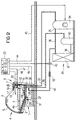
- a product counter according to the invention comprises as main components a counter body 1, a counter trough 2 embedded therein, a goods platform 3, a front pane 5 arranged on the customer side 4 of the counter, on the operating side 6 of the counter a worktop 7, one above the goods platform arranged goods room 8 and one below the goods platform 3 arranged and bordered by the counter tub 2 tub space 9.
- an ascending shaft 10 is arranged, which extends in the longitudinal direction of the counter extending vertical partition 12 substantially from Tub space 9 is delimited.
- the partition 12 does not quite reach the floor, but leaves one Inflow opening 14 between its lower edge and the tub floor 15 free.
- the cooled air comes out at the top of the ascent shaft through a blow-out opening 17 in the direction of flow 18 into the goods space 8 out.
- the blow-out opening 17 is detachably fastened, in particular for Goods compartment 8 towards foldable air filter 19 covered.
- Seen in the direction of flow in front of the air filter 19 is at least one fan 20 with its lower end pivotably arranged such that it with the air filter removed or opened 19 from the blow-out opening 19 to facilitate its cleaning is.
- Between fan 19 and evaporator 16 is one in the longitudinal direction of the counter extending UV disinfection tube 22 positioned.
- the UV disinfection tube 22 acts on the evaporator 16 or its during the defrosting phases Cooling surfaces and the fan with UV radiation. During normal operation the counter, the UV disinfection tube is switched off.
- the goods refrigerated counter includes a control device 23 (see Fig. 2) with which during the defrosting of the evaporator the UV disinfection tube can be switched on, as well as other functions of the Goods refrigerated counter can be monitored and controlled.
- the at least one fan is 20 switched on and circulates the air in the direction of flow 18.
- a cooling device see Fig. 2 connected evaporator
- the air and accordingly, the goods 49 lying on the goods platform 3 are cooled.
- the Airflow constantly takes moisture out of the goods and also from the environment on, which condenses on the evaporator 16. With continued operation, this freezes condensed water to a steadily growing layer of ice and impedes the proper cooling of the circulated air.
- the evaporator is therefore in at regular intervals, for example before the start of sales and at the end of a sales day preferably defrosted as follows: one cooperating with the evaporator 16 Cooling system is switched off while at least one fan 20 continues to heat and thus defrost the evaporator accelerate. The defrosted water runs down on the evaporator and arrives finally on the trough bottom inclined towards a drain opening 25 15. During defrosting, the UV sterilization tube 22 is in operation and acts on the cooling surfaces of the evaporator 16 with UV radiation. An increase of germs contained on the evaporator or in the defrost water The increased temperature of the defrost phase is due to the exposure to Prevents UV radiation. Existing germs are killed.
- a spray head 26 is arranged adjacent to the tub floor 15 via a supply line 27 with interposed check valve 28 is fed to the municipal drinking water supply network.
- the spray head 26 is set so that the cleaning liquid or water in the spray direction 29 ejects.
- the spray direction of the spray head 26 runs in relative proximity to the tub floor 15.
- cleaning liquid passes through the inflow opening 14 also to those located below the evaporator 16 Area of the tub floor 15.
- the spray head 26, the supply line 27 and the spray valve 28 comprising stop valve need not be mandatory for everyone Defrosting operation.
- the evaporator 16 or its connection to the Cooling device 24 designed so that hot gas defrosting is possible.
- the Cooling device 24 is located outside the goods cooling counter, for example in a room under the counter location.
- the evaporator 16 has an evaporator inlet 30 and an evaporator outlet 32.
- the evaporator outlet 32 is connected via a suction line 33 to the input of a compressor 34 connected.
- the outlet 35 of the compressor is connected via a pressure line 36 a condenser 37 fluidly connected. From the capacitor output 38 leads a feed line 39, into which a collector 40 is interposed within the refrigeration system 24 to the evaporator inlet 30.
- a hot gas line 42 which is close to the Heat exchanger 37 opens into the pressure line 36.
- the capacitor 37 bypassed in the manner of a bypass.
- a hot gas shutoff valve 43 is switched on, which is connected via a control line 44 from the control device 23 can be controlled.
- the control device 23 continues to control the compressor 34 via a control line 45, via a control line 46 the shut-off valve 28 of the spray device, the UV disinfection tube via a control line 47 22 and via a control line 48 the at least one Fan 20.
- the cooling or hot gas defrosting device described works as follows: In normal operation, the fan 20 and the refrigeration system 24 are in operation. It will Circulating air flow with flow direction 18 generated on the goods platform 3 lying goods 49 cools.
- the control device 23 is adjustable that at certain time intervals, e.g. at the beginning and end of the Sales day, initiates a defrost process. First the hot gas shut-off valve 43 opened. As a result, what is heated during the compression process arrives Coolant bypassing the heat exchanger 37 directly into the hot gas line 42 and from there via the evaporator inlet 30 into the evaporator 16.
- Zum Defrosting the evaporator requires relatively small amounts of energy because it is not operated in the freezer area.
- the hot gas line 42 which can be very long under certain circumstances become.
- the coolant supplied to the evaporator via line 42 is ambient temperature having.
- a copper tube is preferably used for the hot gas line 42.
- the outer surface of the hot gas line 42 by about Type of fins 50 to enlarge structures formed. Cooling fins are 50 expediently arranged at those points on line 42 where there is an increased room temperature.
- the UV radiation acts on the spatial proximity of the UV sterilization tube to the evaporator 16 whose cooling surfaces and prevents Germ growth during the thawing phase.
- the defrost is due accelerates the heat given off by the sterilization tube.
- a Delay for example towards the end of the defrosting process, becomes the shutoff valve 28 open for water supply for about 5 to 10 seconds. This will Fresh water via the spray head 26 into the counter tub 2 or in the tub room 9 sprayed. The water drained from the evaporator goes into the drain opening 25 rinsed. The same applies to solid particles that are on the tub floor 15 have accumulated.
- the refrigerator is in the process of defrosting or the compressor 34 and the fan 20 in operation. The one from the fan circulated air cools down on the evaporator and prevents heating the goods 49 lying on the goods platform 3.
- the defrosting process is ended when the evaporator 16 is at a predetermined one (Not shown) heated temperature sensor tapped temperature.
- control or the program sequence of the control device can be selected in this way be that not with each defrosting a cleaning of the counter pan 2 Water or cleaning liquid takes place.
- the counter tub can be cleaned directly Water is fed in from the drinking water supply network.
- a storage container in counter body 1 for example to provide for cleaning liquid, the cleaning liquid via a Pump is pumped to the spray head 26 (not shown).
- a cleaning agent can be added to the cleaning liquid in the storage container be added.
- the direct drinking water supply there is a Feeding the tub space 2 with a cleaning agent via a separate one Spray device (not shown).
Landscapes
- Engineering & Computer Science (AREA)
- Physics & Mathematics (AREA)
- Thermal Sciences (AREA)
- Mechanical Engineering (AREA)
- General Engineering & Computer Science (AREA)
- Chemical & Material Sciences (AREA)
- Combustion & Propulsion (AREA)
- Cold Air Circulating Systems And Constructional Details In Refrigerators (AREA)
- Defrosting Systems (AREA)
- Freezers Or Refrigerated Showcases (AREA)
- Devices That Are Associated With Refrigeration Equipment (AREA)
Abstract
Description

- Fig. 1
- eine erfindungsgemäße Warenkühltheke in schematischer Querschnittsdarstellung und
- Fig. 2
- eine Warenkühltheke entsprechend Fig. 1, bei der eine daran angeschlossene Heißgas-Abtaueinrichtung gezeigt ist.
- 1
- Thekenkorpus
- 2
- Thekenwanne
- 3
- Warenplattform
- 4
- Kundenseite
- 5
- Frontscheibe
- 6
- Bedienseite
- 7
- Arbeitsplatte
- 8
- Warenraum
- 9
- Wannenraum
- 10
- Aufstiegsschacht
- 12
- Trennwand
- 13
- Längsleiste
- 14
- Einströmöffnung
- 15
- Wannenboden
- 16
- Verdampfer
- 17
- Ausblaseöffnung
- 18
- Strömungsrichtung
- 19
- Luftfilter
- 20
- Ventilator
- 22
- UV-Entkeimungsröhre
- 23
- Steuereinrichtung
- 24
- Kälteanlage
- 25
- Abflußöffnung
- 26
- Sprühkopf
- 27
- Versorgungsleitung
- 28
- Sperrventil
- 29
- Sprührichtung
- 30
- Verdampfereinlaß
- 31
- Steuerleitung
- 32
- Verdampferauslaß
- 33
- Saugleitung
- 34
- Kompressor
- 35
- Ausgang
- 36
- Druckleitung
- 37
- Kondensator
- 38
- Kondensatorausgang
- 39
- Zuführleitung
- 40
- Sammler
- 42
- Heißgasleitung
- 43
- Heißgassperrventil
- 44
- Steuerleitung
- 45
- Steuerleitung
- 46
- Steuerleitung
- 47
- Steuerleitung
- 48
- Steuerleitung
- 49
- Ware
- 50
- Kühlrippe
Claims (22)
- Warenkühltheke mitdadurch gekennzeichnet,einer Warenplattform (3),einem oberhalb der Warenplattform (3) angeordneten Warenraum (8),einem unterhalb der Warenplattform (3) angeordneten und von einer Thekenwanne (2) umgrenzten Wannenraum (9),wenigstens einem Ventilator (20), undwenigstens einer UV-Entkeimungsröhre (22) und einem Verdampfer (16) zur Kühlung eines Umwälzluftstromes,
daß der Verdampfer an eine Heißgas-Abtaueinrichtung angeschlossen ist und die UV-Entkeimungsröhre derart angeordnet ist, daß sie den Verdampfer während der Abtauphase direkt mit UV-Strahlung beaufschlagt. - Warenkühltheke nach Anspruch 1,
gekennzeichnet durch
eine über ein Heißgas-Sperrventil (43) steuerbare Heißgasleitung (42), mit der der Einlaß (30) des Verdampfers (16) mit der Ausgangsseite des Kompressors (34) einer vorzugsweise entfernt von der Warenkühltheke angeordnete Kälteanlage (24) verbunden ist. - Warenkühltheke nach Anspruch 2,
dadurch gekennzeichnet,
daß die Heißgasleitung (42) von einem wärmedurchlässigen, insbesondere aus Kupfer bestehenden Rohr gebildet ist. - Warenkühltheke nach Anspruch 3,
gekennzeichnet durch
eine Oberflächenvergrößerung der Heißgasleitung (42) insbesondere in Form von Kühlrippen (50). - Warenkühltheke nach Anspruch 4,
gekennzeichnet durch
eine Steuerung der Verdampferabtauung nach vorgegebenen Zeitintervallen. - Warenkühltheke nach einem der Ansprüche 1 bis 5,
dadurch gekennzeichnet,
daß der Verdampfer (16) in einem bedienseitigen, im wesentlichen räumlich vom Wannenraum (9) abgegrenzten und sich vom Wannenboden (15) bis in den Bereich des Warenraums (8) erstreckenden und über eine von einem abnehmbaren Luftfilter (19) überdeckten Ausblaseöffnung (17) in den Warenraum (8) mündenden, als Strömungskanal für die Umwälzluftströmung dienenden Aufstiegsschacht (10) angeordnet ist. - Warenkühltheke nach Anspruch 6,
dadurch gekennzeichnet,
daß der Ventilator (20) im Aufstiegsschacht (10) zwischen dem Verdampfer (16) und dem Luftfilter (19) angeordnet ist. - Warenkühltheke nach Anspruch 7,
dadurch gekennzeichnet,
daß der Ventilator (20) aus der Ausblaseöffnung (17) herausklappbar ist. - Warenkühltheke nach Anspruch 7 oder 8,
dadurch gekennzeichnet,
daß der Ventilator (20) im Wirkungsbereich der UV-Entkeimungsröhre (22) angeordnet ist. - Warenkühltheke nach Anspruch 9,
dadurch gekennzeichnet,
daß die UV-Entkeimungsröhre (22) zwischen dem Ventilator (20) und dem Verdampfer (16) angeordnet ist. - Warenkühltheke nach einem der Ansprüche 1 bis 10,
dadurch gekennzeichnet,
daß der Wannenboden (15) zu einer Abflußöffnung (25) hin geneigt ist und daß im Wannenraum (9) eine zumindest den Wannenboden (15) mit Reinigungsflüssigkeit beaufschlagende Sprüheinrichtung angeordnet ist. - Warenkühltheke nach Anspruch 11,
dadurch gekennzeichnet,
daß die Sprüheinrichtung wenigstens einen am Wannenboden (15) angeordneten Sprühkopf (26) umfaßt. - Warenkühltheke nach Anspruch 11 oder 12,
dadurch gekennzeichnet,
daß die Sprüheinrichtung direkt aus einem kommunalen Trinkwasserversorgungsnetz gespeist ist. - Warenkühltheke nach Anspruch 11,12 oder 13,
gekennzeichnet durch
eine zweite Sprüheinrichtung für ein Reinigungsmittel, die fluidisch von der trinkwassergespeisten Sprüheinrichtung getrennt ist. - Warenkühltheke nach Anspruch 11 oder 12,
dadurch gekennzeichnet,
daß die Sprüheinrichtung aus einem vorzugsweise unterhalb der Thekenwanne (2) angeordneten Vorratsbehälter gespeist ist. - Warenkühltheke nach einem der Ansprüche 11 bis 15,
dadurch gekennzeichnet,
daß der Wannenraum (9) im wesentlichen einbautenfrei ist. - Warenkühltheke nach einem der Ansprüche 1 bis 16,
gekennzeichnet durch
eine Steuereinrichtung, mit der die Heißgas-Abtaueinrichtung, die Sprüheinrichtung, der Ventilator (20) und die UV-Entkeimungsröhre (22) steuerbar ist. - Verfahren zur Hygienisierung einer Warenkühltheke nach einem der Ansprüche 1 bis 17,
gekennzeichnet durch,
eine Heißgasabtauung des Verdampfers (16), während der er mit UV-Strahlung beaufschlagt wird. - Verfahren nach Anspruch 18,
dadurch gekennzeichnet,
daß das vom Verdampfer (16) auf den Wannenboden (15) abtropfende Wasser von dort mit Wasser und/oder einer Reinigungsflüssigkeit weggespült wird. - Verfahren nach Anspruch 18 oder 19,
gekennzeichnet durch,
eine Heißgasabtauung, bei der das den Kompressor (34) einer Kälteanlage (24) verlassende erwärmte Kühlmittel direkt dem Verdampfer (16) zugeführt wird. - Verfahren nach Anspruch 20,
dadurch gekennzeichnet,
daß das dem Verdampfer (16) zugeführte Kühlmittel etwa Raumtemperatur aufweist. - Verfahren nach einem der Ansprüche 18 bis 21,
dadurch gekennzeichnet,
daß die Abtauung des Verdampfers (16), das Wegspülen des während des Abtauens vom Verdampfer abtropfenden Wassers, die UV-Entkeimung des Verdampfers sowie das Ein- und Ausschalten des Ventilators (20) mit Hilfe einer Steuereinrichtung (23) automatisch durchgeführt wird.
Applications Claiming Priority (2)
| Application Number | Priority Date | Filing Date | Title |
|---|---|---|---|
| DE19749971 | 1997-11-05 | ||
| DE19749971A DE19749971A1 (de) | 1997-11-05 | 1997-11-05 | Warenkühltheke und Verfahren zu ihrer Abtauung |
Publications (2)
| Publication Number | Publication Date |
|---|---|
| EP0916291A1 true EP0916291A1 (de) | 1999-05-19 |
| EP0916291B1 EP0916291B1 (de) | 2001-05-09 |
Family
ID=7848389
Family Applications (1)
| Application Number | Title | Priority Date | Filing Date |
|---|---|---|---|
| EP98120732A Expired - Lifetime EP0916291B1 (de) | 1997-11-05 | 1998-10-31 | Warenkühltheke und Hygienisierungsverfahren für eine Warenkühltheke |
Country Status (5)
| Country | Link |
|---|---|
| US (1) | US6237350B1 (de) |
| EP (1) | EP0916291B1 (de) |
| AT (1) | ATE200963T1 (de) |
| DE (2) | DE19749971A1 (de) |
| ES (1) | ES2157634T3 (de) |
Cited By (4)
| Publication number | Priority date | Publication date | Assignee | Title |
|---|---|---|---|---|
| DE10040204A1 (de) * | 2000-08-17 | 2002-02-28 | Linde Ag | Externe Kaltlufterzeugung in Großmärkten |
| US6889518B2 (en) * | 2001-08-22 | 2005-05-10 | Delaware Capital Formation, Inc. | Service case |
| US6981385B2 (en) | 2001-08-22 | 2006-01-03 | Delaware Capital Formation, Inc. | Refrigeration system |
| US12498147B2 (en) | 2020-02-19 | 2025-12-16 | Hill Phoenix, Inc. | Thermoelectric cooling system |
Families Citing this family (19)
| Publication number | Priority date | Publication date | Assignee | Title |
|---|---|---|---|---|
| DE10014343A1 (de) * | 2000-03-24 | 2001-09-27 | Hertel Guenther | Warenkühltheke |
| US6438983B1 (en) * | 2000-10-02 | 2002-08-27 | Tyler Refrigeration Corporation | Dipping cabinet with improved lighting |
| US6679080B2 (en) * | 2001-05-04 | 2004-01-20 | Carrier Corporation | Medium temperature refrigerated merchandiser |
| US8151587B2 (en) * | 2001-05-04 | 2012-04-10 | Hill Phoenix, Inc. | Medium temperature refrigerated merchandiser |
| US6923013B2 (en) * | 2001-05-04 | 2005-08-02 | Carrier Corporation | Evaporator for medium temperature refrigerated merchandiser |
| DE10324685B4 (de) * | 2003-05-30 | 2006-03-30 | Glasbau Hahn Gmbh + Co. Kg | Vitrine zur Aufbewahrung und/oder Zurschaustellung von Gegenständen |
| ITUD20030023U1 (it) * | 2003-06-04 | 2004-12-05 | Ind Scaffalature Arredamenti Isa Spa | Espositore per alimenti |
| US7159413B2 (en) | 2003-10-21 | 2007-01-09 | Delaware Capital Formation, Inc. | Modular refrigeration system |
| US7263843B1 (en) * | 2004-04-20 | 2007-09-04 | Mark T. Nordstrom | Display case with improved sanitation |
| AU2005327823A1 (en) * | 2005-02-15 | 2006-08-24 | Carrier Corporation | Refrigerated display case |
| RU2355275C1 (ru) * | 2005-02-15 | 2009-05-20 | Кэрриер Корпорейшн | Витрина-холодильник |
| US20070196244A1 (en) * | 2006-02-22 | 2007-08-23 | Croft Carlton R | Air/water sterilization system for ice machine |
| US9675186B2 (en) | 2010-08-31 | 2017-06-13 | Hussmann Corporation | Merchandiser including venting frame for top containers |
| EP2478798A1 (de) * | 2011-01-25 | 2012-07-25 | Franz Hilberer | Vorrichtung zur Kühlung von Lebensmitteln |
| EP2634515B1 (de) * | 2012-02-29 | 2019-09-04 | Electrolux Professional S.p.A. | Schockkühlervorrichtung und Verfahren zum Säubern einer Schockkühlervorrichtung |
| DE102013010399B4 (de) * | 2013-06-18 | 2020-08-27 | Dietmar Köhler | Keimfrei betreibbarer temperierbarer Kühlschrank |
| US10001306B2 (en) * | 2014-10-09 | 2018-06-19 | Scottsman Group LLC | Ice-making freezer cleaning |
| ES2535685B1 (es) * | 2014-12-23 | 2015-09-30 | Sergio GONZÁLEZ MORLANS | Vitrina refrigerada |
| DE202016101554U1 (de) * | 2016-03-22 | 2017-06-26 | Götz Gastroküchen GmbH | Kühlhochschrank |
Citations (4)
| Publication number | Priority date | Publication date | Assignee | Title |
|---|---|---|---|---|
| DE3708390A1 (de) * | 1987-03-14 | 1988-09-22 | Karl Leuprecht | Kuehltheke |
| EP0312060A2 (de) * | 1987-10-14 | 1989-04-19 | INDUSTRIE ZANUSSI S.p.A. | Automatisches Kältegerät mit einem keimfreien Lagerfach |
| EP0797944A2 (de) * | 1996-03-26 | 1997-10-01 | Günther Hertel | Warentheke, insbesondere Kühltheke |
| EP0835623A2 (de) * | 1996-10-09 | 1998-04-15 | Hertel, Günther | Kühltheke |
Family Cites Families (7)
| Publication number | Priority date | Publication date | Assignee | Title |
|---|---|---|---|---|
| US3561230A (en) * | 1969-03-17 | 1971-02-09 | Streater Ind Inc | Floor pan arrangement for refrigerated display case |
| US4315414A (en) * | 1980-05-05 | 1982-02-16 | Tyler Refrigeration Corporation | Automatic cleaning of refrigerated case interior surfaces |
| US4416120A (en) * | 1982-08-06 | 1983-11-22 | Munim Yono | Spray assembly for refrigerated display cases |
| US4990313A (en) * | 1990-01-12 | 1991-02-05 | American Ultra Air, Inc. | Ultraviolet device |
| US5755103A (en) * | 1995-09-16 | 1998-05-26 | Samsung Electronics Co., Ltd. | Room air conditioner with sterilizing apparatus |
| DE19616358C1 (de) * | 1996-04-24 | 1997-07-24 | Hertel Guenther | Warentheke, insbesondere Kühltheke |
| US5817276A (en) * | 1997-02-20 | 1998-10-06 | Steril-Aire U.S.A., Inc. | Method of UV distribution in an air handling system |
-
1997
- 1997-11-05 DE DE19749971A patent/DE19749971A1/de not_active Ceased
-
1998
- 1998-10-31 AT AT98120732T patent/ATE200963T1/de active
- 1998-10-31 EP EP98120732A patent/EP0916291B1/de not_active Expired - Lifetime
- 1998-10-31 DE DE59800685T patent/DE59800685D1/de not_active Expired - Lifetime
- 1998-10-31 ES ES98120732T patent/ES2157634T3/es not_active Expired - Lifetime
- 1998-11-04 US US09/185,621 patent/US6237350B1/en not_active Expired - Lifetime
Patent Citations (4)
| Publication number | Priority date | Publication date | Assignee | Title |
|---|---|---|---|---|
| DE3708390A1 (de) * | 1987-03-14 | 1988-09-22 | Karl Leuprecht | Kuehltheke |
| EP0312060A2 (de) * | 1987-10-14 | 1989-04-19 | INDUSTRIE ZANUSSI S.p.A. | Automatisches Kältegerät mit einem keimfreien Lagerfach |
| EP0797944A2 (de) * | 1996-03-26 | 1997-10-01 | Günther Hertel | Warentheke, insbesondere Kühltheke |
| EP0835623A2 (de) * | 1996-10-09 | 1998-04-15 | Hertel, Günther | Kühltheke |
Cited By (4)
| Publication number | Priority date | Publication date | Assignee | Title |
|---|---|---|---|---|
| DE10040204A1 (de) * | 2000-08-17 | 2002-02-28 | Linde Ag | Externe Kaltlufterzeugung in Großmärkten |
| US6889518B2 (en) * | 2001-08-22 | 2005-05-10 | Delaware Capital Formation, Inc. | Service case |
| US6981385B2 (en) | 2001-08-22 | 2006-01-03 | Delaware Capital Formation, Inc. | Refrigeration system |
| US12498147B2 (en) | 2020-02-19 | 2025-12-16 | Hill Phoenix, Inc. | Thermoelectric cooling system |
Also Published As
| Publication number | Publication date |
|---|---|
| DE59800685D1 (de) | 2001-06-13 |
| DE19749971A1 (de) | 1999-05-06 |
| ATE200963T1 (de) | 2001-05-15 |
| EP0916291B1 (de) | 2001-05-09 |
| US6237350B1 (en) | 2001-05-29 |
| ES2157634T3 (es) | 2001-08-16 |
Similar Documents
| Publication | Publication Date | Title |
|---|---|---|
| EP0916291B1 (de) | Warenkühltheke und Hygienisierungsverfahren für eine Warenkühltheke | |
| DE69319695T2 (de) | Vorrichtung zur Sammlung von Trinkwasser aus der Atmosphäre | |
| EP2322072B1 (de) | Geschirrspüler mit Latentwärmespeicher | |
| DE1401509A1 (de) | Kuehlanlage | |
| DE3028280A1 (de) | Kocheinrichtung | |
| DE69619050T2 (de) | Niedrigtemperatur-Schauvitrine | |
| DE1501036A1 (de) | Wasserkuehlsystem fuer Kuehlanlagen | |
| DE202011110116U1 (de) | Kühlmöbel mit einem mittels kalter Außenluft kühlbaren Kühlraum | |
| DE1517363A1 (de) | Verfahren und Vorrichtung zur Reinigung von Fluessigkeiten | |
| DE102011083179B4 (de) | Transportspülmaschine und Verfahren zum Betreiben einer Transportspülmaschine | |
| EP2378227A1 (de) | Kühlschrank | |
| DE2729878A1 (de) | Waermerueckgewinnungseinrichtung, insbesondere fuer spuelanlagen | |
| DE19833196A1 (de) | Wärmegewinnung aus dem Kondensator eines steckerfertigen Kühlregals | |
| DE102017114547B3 (de) | Kühlgerät sowie Verfahren zum Reinigen eines Kühlgeräts | |
| DE19641474C2 (de) | Kühltheke | |
| AT410276B (de) | Pökelmaschine | |
| DE3007894A1 (de) | Tiefkuehltruhe | |
| DE3116685C2 (de) | ||
| EP0571331B1 (de) | Kühlmöbel | |
| DE3001995A1 (de) | Verdampfer- und kuehlvorrichtung z.b. fuer rotationskolbenverdampfer | |
| DE2540037A1 (de) | Kuehleinrichtung | |
| DE2926256A1 (de) | Trocknungsverfahren, insbesondere fuer getreide | |
| EP1889558B1 (de) | Befeuchtungseinrichtung für eine Warentheke | |
| DE2802774A1 (de) | Abtaueinrichtung fuer ein kuehlmoebel mit kompressorgetriebenem kaelteapparat | |
| DE202011104868U1 (de) | Kühlmöbel, insbesondere Kühlregal |
Legal Events
| Date | Code | Title | Description |
|---|---|---|---|
| PUAI | Public reference made under article 153(3) epc to a published international application that has entered the european phase |
Free format text: ORIGINAL CODE: 0009012 |
|
| AK | Designated contracting states |
Kind code of ref document: A1 Designated state(s): AT DE ES FR GB IT |
|
| AX | Request for extension of the european patent |
Free format text: AL;LT;LV;MK;RO;SI |
|
| 17P | Request for examination filed |
Effective date: 19990813 |
|
| AKX | Designation fees paid |
Free format text: AT DE ES FR GB IT |
|
| GRAG | Despatch of communication of intention to grant |
Free format text: ORIGINAL CODE: EPIDOS AGRA |
|
| 17Q | First examination report despatched |
Effective date: 20000629 |
|
| GRAG | Despatch of communication of intention to grant |
Free format text: ORIGINAL CODE: EPIDOS AGRA |
|
| GRAH | Despatch of communication of intention to grant a patent |
Free format text: ORIGINAL CODE: EPIDOS IGRA |
|
| GRAH | Despatch of communication of intention to grant a patent |
Free format text: ORIGINAL CODE: EPIDOS IGRA |
|
| GRAA | (expected) grant |
Free format text: ORIGINAL CODE: 0009210 |
|
| AK | Designated contracting states |
Kind code of ref document: B1 Designated state(s): AT DE ES FR GB IT |
|
| REF | Corresponds to: |
Ref document number: 200963 Country of ref document: AT Date of ref document: 20010515 Kind code of ref document: T |
|
| REF | Corresponds to: |
Ref document number: 59800685 Country of ref document: DE Date of ref document: 20010613 |
|
| ITF | It: translation for a ep patent filed | ||
| REG | Reference to a national code |
Ref country code: ES Ref legal event code: FG2A Ref document number: 2157634 Country of ref document: ES Kind code of ref document: T3 |
|
| GBT | Gb: translation of ep patent filed (gb section 77(6)(a)/1977) |
Effective date: 20010730 |
|
| ET | Fr: translation filed | ||
| REG | Reference to a national code |
Ref country code: GB Ref legal event code: IF02 |
|
| PLBE | No opposition filed within time limit |
Free format text: ORIGINAL CODE: 0009261 |
|
| STAA | Information on the status of an ep patent application or granted ep patent |
Free format text: STATUS: NO OPPOSITION FILED WITHIN TIME LIMIT |
|
| 26N | No opposition filed | ||
| REG | Reference to a national code |
Ref country code: DE Ref legal event code: R082 Ref document number: 59800685 Country of ref document: DE Representative=s name: TERGAU & WALKENHORST PATENTANWAELTE PARTGMBB, DE Ref country code: DE Ref legal event code: R082 Ref document number: 59800685 Country of ref document: DE Representative=s name: TERGAU & WALKENHORST PATENT- UND RECHTSANWAELT, DE |
|
| REG | Reference to a national code |
Ref country code: FR Ref legal event code: PLFP Year of fee payment: 18 |
|
| REG | Reference to a national code |
Ref country code: FR Ref legal event code: PLFP Year of fee payment: 19 |
|
| REG | Reference to a national code |
Ref country code: FR Ref legal event code: PLFP Year of fee payment: 20 |
|
| PGFP | Annual fee paid to national office [announced via postgrant information from national office to epo] |
Ref country code: DE Payment date: 20171024 Year of fee payment: 20 Ref country code: FR Payment date: 20171023 Year of fee payment: 20 |
|
| PGFP | Annual fee paid to national office [announced via postgrant information from national office to epo] |
Ref country code: GB Payment date: 20171024 Year of fee payment: 20 Ref country code: IT Payment date: 20171020 Year of fee payment: 20 Ref country code: AT Payment date: 20171018 Year of fee payment: 20 Ref country code: ES Payment date: 20171103 Year of fee payment: 20 |
|
| REG | Reference to a national code |
Ref country code: DE Ref legal event code: R071 Ref document number: 59800685 Country of ref document: DE |
|
| REG | Reference to a national code |
Ref country code: GB Ref legal event code: PE20 Expiry date: 20181030 |
|
| REG | Reference to a national code |
Ref country code: AT Ref legal event code: MK07 Ref document number: 200963 Country of ref document: AT Kind code of ref document: T Effective date: 20181031 |
|
| PG25 | Lapsed in a contracting state [announced via postgrant information from national office to epo] |
Ref country code: GB Free format text: LAPSE BECAUSE OF EXPIRATION OF PROTECTION Effective date: 20181030 |
|
| REG | Reference to a national code |
Ref country code: ES Ref legal event code: FD2A Effective date: 20201030 |
|
| PG25 | Lapsed in a contracting state [announced via postgrant information from national office to epo] |
Ref country code: ES Free format text: LAPSE BECAUSE OF EXPIRATION OF PROTECTION Effective date: 20181101 |