EP0908930A2 - Dispositif de commande de fluide - Google Patents
Dispositif de commande de fluide Download PDFInfo
- Publication number
- EP0908930A2 EP0908930A2 EP19980119271 EP98119271A EP0908930A2 EP 0908930 A2 EP0908930 A2 EP 0908930A2 EP 19980119271 EP19980119271 EP 19980119271 EP 98119271 A EP98119271 A EP 98119271A EP 0908930 A2 EP0908930 A2 EP 0908930A2
- Authority
- EP
- European Patent Office
- Prior art keywords
- fluid control
- channel
- couplings
- members
- control apparatus
- Prior art date
- Legal status (The legal status is an assumption and is not a legal conclusion. Google has not performed a legal analysis and makes no representation as to the accuracy of the status listed.)
- Granted
Links
Images

Classifications
-
- F—MECHANICAL ENGINEERING; LIGHTING; HEATING; WEAPONS; BLASTING
- F16—ENGINEERING ELEMENTS AND UNITS; GENERAL MEASURES FOR PRODUCING AND MAINTAINING EFFECTIVE FUNCTIONING OF MACHINES OR INSTALLATIONS; THERMAL INSULATION IN GENERAL
- F16K—VALVES; TAPS; COCKS; ACTUATING-FLOATS; DEVICES FOR VENTING OR AERATING
- F16K27/00—Construction of housing; Use of materials therefor
- F16K27/003—Housing formed from a plurality of the same valve elements
-
- Y—GENERAL TAGGING OF NEW TECHNOLOGICAL DEVELOPMENTS; GENERAL TAGGING OF CROSS-SECTIONAL TECHNOLOGIES SPANNING OVER SEVERAL SECTIONS OF THE IPC; TECHNICAL SUBJECTS COVERED BY FORMER USPC CROSS-REFERENCE ART COLLECTIONS [XRACs] AND DIGESTS
- Y10—TECHNICAL SUBJECTS COVERED BY FORMER USPC
- Y10T—TECHNICAL SUBJECTS COVERED BY FORMER US CLASSIFICATION
- Y10T137/00—Fluid handling
- Y10T137/8593—Systems
- Y10T137/877—With flow control means for branched passages
- Y10T137/87885—Sectional block structure
Definitions
- the present invention relates to fluid control apparatus, for example, for use in semiconductor manufacturing equipment.
- JP-A No. 172265/1993 proposes a unit of at least three monofunctional members (such as a filter, massflow controller and on-off valve) which are directly connected together (integrated).
- An object of the present invention is to provide a fluid control apparatus which fulfills all the requirements of integration, reduction in the number of components and facilitated maintenance.
- Another object of the invention is to provide a fluid control apparatus which further fulfills the requirement of reduced pressure losses.
- the present invention provides a fluid control apparatus comprising a plurality of fluid control members arranged at an upper level and a plurality of couplings arranged at a lower level, at least one of the fluid control members comprising a plurality of monofunctional members integrally provided on a blocklike body, the blocklike body being mounted on at least one of the couplings so as to be removable upward.
- the fluid control member is, for example, a unit of two or three on-off valves as mounted on a blocklike body, or a unit of a pressure regulator and a pressure sensor which are mounted on a blocklike body.
- a plurality of monofunctional members are integrally provided on a blocklike body. This reduces the number of components such as blocklike bodies and seal members.
- the fluid control member is removed upward from the apparatus, and the particular monofunctional member is then replaced, hence facilitated maintenance. It is desired that monofunctional members which require replacement less frequently be integrally provided on a single blocklike body as a fluid control member, and that monofunctional members which are to be replaced frequently be used singly as individual fluid control members. Both the reduction in the number of components and ease of maintenance can then be attained readily.
- At least one of the couplings which causes one of the fluid control members to communicate with the fluid control member adjacent thereto is a blocklike coupling having a V-shaped communication channel.
- the two adjacent fluid control members can then be held in communication with each other by the single coupling. This results in a further reduction in the number of components.
- At least one of the couplings which causes one of the fluid control members to communicate with the fluid control member adjacent thereto comprises two blocklike components butting against each other to form a U-shaped communication channel.
- the cross sectional area of the channel is smaller than the area of the opening thereof by an amount attributable to the inclination of the channel, whereas the cross sectional area of the U-shaped channel can be the same as the opening area thereof.
- the U-shaped channel can therefore be given a greater diameter than the V-shaped channel, consequently reducing the pressure loss involved in the fluid control apparatus.
- FIG. 1 the left-hand side and the right-hand side of FIG. 1 will be referred to as left and right, respectively.
- the front side of the plane of the drawing will be referred to as front, and the rear side thereof as rear.
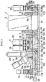
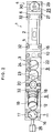
- FIGS. 1 and 2 show a fluid control apparatus 1 as a first embodiment of the invention.
- the apparatus 1 which is adapted for use in semiconductor manufacturing equipment or the like comprises a massflow controller 2, an inlet-side on-off-opening assembly 3 provided at the left of the controller 2, and an outlet-side shutoff-opening assembly 4 disposed at the right of the controller 2.
- a left extension block (first fluid control member) 5 in the form of a rectangular parallelepiped and formed with an inlet channel 5a which has an opening in the bottom surface of the block.
- a right extension block (second fluid control member) 6 in the form of a rectangular parallelepiped and formed with an outlet channel 6a which has an opening in the bottom surface of the block.
- the extension blocks 5, 6 are fastened to the body of the controller 2 with screws driven in laterally.
- the inlet-side shutoff-opening assembly 3 comprises third to sixth four fluid control members 7, 8, 9, 10 arranged at an upper level, and first to fifth five rectangular parallelepipedal couplings 11, 12, 13, 14, 15 arranged at a lower level.
- the third fluid control member 7, which is disposed at the left end of the assembly 3, comprises a first on-off valve 17 integral with a blocklike body 16 having an inlet channel 16a and an outlet channel 16b which extend downward, the valve 17 being operable to bring these channels 16a, 16b into and out of communication with each other.
- the fourth fluid control member 8 which is the second component from the left end of the assembly 3, comprises a blocklike body 18 generally in the form of a rectangular parallelepiped, having a top left portion providing a slope and having an inlet channel 18a and an outlet channel 18b which extend downward; a pressure regulator 19 mounted on the slope of the body 18 and disposed at a portion of communication between the channels 18a, 18b for giving a regulated pressure; and a pressure sensor 20 mounted on a flat portion at the top left part of the body 18 for measuring fluid pressure through a channel communicating with the outlet channel 18b.
- the inlet channel 18a of the body 18 has a filter 21.
- the fifth fluid control member 9, which is the third component from the left end of the assembly 3, comprises second and third on-off valves 23, 24 which are integral with one blocklike body 22 in the form of a rectangular parallelepiped.
- the body 22 has a downward first inlet channel 22a formed in its left end, a rightward outlet channel 22b communicating with the channel 22a through the second on-off valve 23, and a downward second inlet channel 22c communicating with the outlet channel 22b through the third on-off valve 24.
- the sixth fluid control member 10, which is the fourth component from the left end of the assembly 3, comprises a rectangular parallelepipedal channel block.
- the member 10 is formed with a communication channel 10a having one end communicating with the outlet channel 22b of the fifth fluid control member 22 and the other end which is open downward.
- the first coupling 11 which is disposed at the left end of the inlet-side shutoff-opening assembly 3, has an L-shaped upstream communication channel 11a opened leftward and communicating with the inlet channel 16a of the third fluid control member body 16, and an L-shaped downstream communication channel 11b opened rightward and communicating with the outlet channel 16b of the body 16.
- a first inlet pipe joint 25 communicating with the upstream communication channel 11a.
- the second coupling 12 which is disposed as the second from the left end of the assembly 3, has an L-shaped upstream communication channel 12a for holding the outlet channel 11b of the first coupling 11 in communication with the inlet channel 18a of the fourth fluid control member body 18, and an L-shaped downstream communication channel 12b having one end communicating with the outlet channel 18b of the body 18 and the other end opened rightward.
- the third coupling 13, which is disposed as the third from the left end of the assembly 3, has an L-shaped communication channel 13a for holding the outlet channel 12b of the second coupling 12 in communication with the first inlet channel 22a of the fifth fluid control member body 22.
- the fourth coupling 14 which is the fourth from the left end of the assembly 3, is formed with a communication channel 14a having one end communicating with the second inlet channel 22c of the fifth fluid control member body 22 and the other end opened rearward. Disposed on the rear side of the fourth coupling 14 is a second inlet pipe joint (not shown) communicating with the channel 14a.
- the fifth coupling 15, which is the fifth from the left end of the assembly 3, is formed with a V-shaped communication channel 15a having one end communicating with the outlet of communication channel 10a of the sixth fluid control member 10 and the other end communicating with the inlet channel 5a of left extension block 5 of the massflow controller 2.
- the outlet-side or downstream shutoff-opening assembly 4 comprises a seventh fluid control member 26 disposed at an upper level, and sixth and seventh rectangular parallelepipedal couplings 27, 28 which are arranged at a lower level.
- the seventh fluid control member 26 comprises a fourth on-off valve 30 integral with a blocklike body 29 having an inlet channel 29a and an outlet channel 29b which extend downward, the valve 30 being operable to bring these channels 29a, 29b into and out of communication with each other.
- the sixth coupling 27 disposed at the left side of the assembly 4 is formed with a V-shaped communication channel 27a having one end communicating with the outlet channel 6a of right extension block 6 of the massflow controller 2 and the other end communicating with the inlet channel 29a of the seventh fluid control member body 29.
- the seventh coupling 28 disposed at the right end of the assembly 4 is formed with a communication channel 28a having one end communicating with the outlet channel 29b of the body 29 and the other end opened rearward. Disposed on the rear side of the seventh coupling 28 is an outlet pipe joint (not shown) communicating with the channel 28a.
- the bottom surfaces of the fluid control members 5, 6, 7, 8, 9, 10, 26 are all flush with one another.
- the upper surfaces of the couplings 11, 12, 13, 14, 15 are also flush with one another.
- the couplings 11, 12, 13, 14, 15, 27, 28 are fixed to a base plate 31.
- the fluid control members 5, 6, 7, 8, 9, 10, 26 are fixed to at least one of the couplings 11, 12, 13, 14, 15, 27, 28 with screws 32 from above.
- Different fluids are introduced into the fluid control apparatus 1 respectively through the first inlet pipe joint 25 of the first coupling 11 and the second inlet pipe joint of the fourth coupling 14. These fluids as suitably changed over from one to the other are passed through the controller 2 and discharged from the outlet pipe joint of the seventh coupling 28.
- the massflow controller 2 can be taken out upward along with the left and right extension blocks 5, 6.
- the third to seventh fluid control members 7, 8, 9, 10, 26 can also be removed upward individually. For example, if there arises a need to replace the pressure regulator 19, the fourth fluid control member 8 is removed in its entirety, followed by the replacement of the regulator 19, and the resulting member 8 is entirely reinstalled in the original position. Further when a need arises to replace one of the second and third on-off valves 23, 24 included in the fifth fluid control member 9, the entire fifth member 9 is removed, followed by the replacement, and the resulting fifth member 9 is entirely reinstalled in position.
- a seal 33 is provided in each of the portions of communication between the fluid control members 5, 6, 7, 8, 9, 10, 26, the portions of communication between the couplings 11, 12, 13, 14, 15 and the portions of communication between the fluid control members 5, 6, 7, 8, 9, 10, 26 and the couplings 11, 12, 13, 14, 15.
- the fluid control apparatus 1 according to the first embodiment has the seal 33 at each of 13 locations.
- the inlet-side and outlet-side shutoff-opening assemblies 3, 4 of the above embodiment are not limitative. It is possible, for example, to remove the fourth fluid control member 8 from the inlet-side assembly 3, to add the same member as the fifth fluid control member 9 of the assembly 3 to the outlet-side assembly 4, or to provide the same member in place of the seventh fluid control member 26.
- the pressure regulator 19 and the pressure sensor 20 are fixed to the blocklike body 18 of the fourth fluid control member 8 by welding or screw-thread engagement.
- FIG. 3 shows another fluid control apparatus as a second embodiment of the invention.
- the second embodiment differs from the first in that the first, second and third couplings 11, 12, 13 of the first embodiment is replaced by a single rectangular parallelepipedal coupling (eighth coupling) 41.
- the eighth coupling 41 is formed with an upstream communication channel 41a having one end communicating with the inlet channel 16a of the third fluid control member body 16 and the other end opened leftward, a first V-shaped communication channel 41b having one end communicating with the outlet channel 16b of the body 16 and the other end communicating with the inlet channel 18a of the fourth fluid control member body 18, and a second V-shaped communication channel 41c having one end communicating with the outlet channel 18b of the body 18 and the other end communicating with the first inlet channel 22a of the fifth fluid control member body 22.
- the first inlet pipe joint 25 communicating with the upstream communication channel 41a.
- the eighth coupling 41 has a greater height than the first, second and third couplings 11, 12, 13 of the first embodiment, and the channel 41b has a greater depth than the second V-shaped communication channel 41c.
- the fourth, fifth, sixth and seventh couplings 14, 15, 27, 28 are given the same height as the eighth coupling 41, with their communication channels 14a, 15a, 27a, 28a remaining unaltered in depth.
- the second embodiment has the same construction as the first with the exception of the above features, and like parts are designated by like reference numerals or symbols and will not be described repeatedly.
- the second embodiment is smaller than the first by two in the number of seals 33 and by two also in the number of couplings.
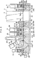
- FIG. 4 shows another fluid control apparatus as a third embodiment of the invention.
- the third embodiment differs from the first in that the fifth and sixth couplings 15, 27 of the first embodiment, i.e., the couplings 15, 27 having the respective V-shaped communication channels 15a, 27a, are replaced respectively by couplings (ninth and tenth couplings) 51, 54 each comprising two rectangular parallelepipedal components and having a U-shaped communication channel.
- the ninth coupling 51 comprises a first component 52 and a second component 53.
- the first component 52 is formed with an L-shaped upstream communication channel 52a having one end communicating with the outlet of communication channel 10a of the sixth fluid control member body 10 and the other end opened rightward.
- the second component 53 is formed with an L-shaped downstream communication channel 53a having one end communicating with the upstream communication channel 52a of the first component 52 and the other end communicating with the inlet channel 5a of left extension block 5 of the massflow controller 2.
- the first and second components 52, 53 are fitted to each other with a seal 33 interposed therebetween so as to cause the upstream channel 52a to communicate with the downstream channel 53a, whereby a U-shaped communication channel 51a is formed in the ninth coupling 51 for holding the channel 10a of the sixth fluid control member body 10 in communication with the inlet channel 5a of left extension block 5 of the massflow controller 2.
- the tenth coupling 54 comprises a first component 55 and a second component 56.
- the first component 55 is formed with an L-shaped upstream communication channel 55a having one end communicating with the outlet channel 6a of right extension block 6 of the massflow controller 2 and the other end opened rightward.
- the second component 56 is formed with an L-shaped downstream communication channel 56a having one end communicating with the upstream communication channel 55a of the first component 55 and the other end communicating with the inlet channel 29a of the seventh fluid control member body 29.
- the first and second components 55, 56 are fitted to each other with a seal 33 interposed therebetween so as to cause the upstream channel 55a to communicate with the downstream channel 56a, whereby a U-shaped communication channel 54a is formed in the tenth coupling 54 for holding the outlet channel 6a of right extension block 6 of the massflow controller 2 in communication with the inlet channel 29a of the seventh fluid control member body 29.
- the third embodiment has the same construction as the first, and like parts are designated by like reference numerals or symbols and will not be described repeatedly.
Applications Claiming Priority (3)
| Application Number | Priority Date | Filing Date | Title |
|---|---|---|---|
| JP27849597 | 1997-10-13 | ||
| JP278495/97 | 1997-10-13 | ||
| JP27849597A JP4378553B2 (ja) | 1997-10-13 | 1997-10-13 | 流体制御装置 |
Publications (4)
| Publication Number | Publication Date |
|---|---|
| EP0908930A2 true EP0908930A2 (fr) | 1999-04-14 |
| EP0908930A3 EP0908930A3 (fr) | 2002-09-25 |
| EP0908930B1 EP0908930B1 (fr) | 2008-11-12 |
| EP0908930B8 EP0908930B8 (fr) | 2009-03-25 |
Family
ID=17598122
Family Applications (1)
| Application Number | Title | Priority Date | Filing Date |
|---|---|---|---|
| EP19980119271 Expired - Lifetime EP0908930B8 (fr) | 1997-10-13 | 1998-10-13 | Dispositif de commande de fluide |
Country Status (8)
| Country | Link |
|---|---|
| US (1) | US6273139B1 (fr) |
| EP (1) | EP0908930B8 (fr) |
| JP (1) | JP4378553B2 (fr) |
| KR (1) | KR100622954B1 (fr) |
| CA (1) | CA2249925C (fr) |
| DE (1) | DE69840204D1 (fr) |
| IL (1) | IL126530A (fr) |
| TW (1) | TW360758B (fr) |
Cited By (1)
| Publication number | Priority date | Publication date | Assignee | Title |
|---|---|---|---|---|
| KR100622954B1 (ko) * | 1997-10-13 | 2007-06-07 | 다다히로 오미 | 유체제어장치 |
Families Citing this family (38)
| Publication number | Priority date | Publication date | Assignee | Title |
|---|---|---|---|---|
| US6293310B1 (en) * | 1996-10-30 | 2001-09-25 | Unit Instruments, Inc. | Gas panel |
| US6817381B2 (en) * | 1999-08-24 | 2004-11-16 | Tokyo Electron Limited | Gas processing apparatus, gas processing method and integrated valve unit for gas processing apparatus |
| JP2001147722A (ja) * | 1999-11-22 | 2001-05-29 | Ace:Kk | ガス流量制御装置 |
| JP3482601B2 (ja) * | 2000-06-30 | 2003-12-22 | 東京エレクトロン株式会社 | 流体制御装置 |
| JP2002089798A (ja) * | 2000-09-11 | 2002-03-27 | Ulvac Japan Ltd | 流体制御装置およびこれを用いたガス処理装置 |
| JP4487135B2 (ja) * | 2001-03-05 | 2010-06-23 | 東京エレクトロン株式会社 | 流体制御装置 |
| US20030079786A1 (en) * | 2001-10-30 | 2003-05-01 | Diana Michael J. | Modular fluid pressure regulator with bypass |
| EP1543544A2 (fr) * | 2002-08-27 | 2005-06-22 | Celerity Group, Inc. | Panneau de gaz a substrat modulaire comprenant des raccordements de collecteur dans un plan commun |
| JP4092164B2 (ja) * | 2002-09-20 | 2008-05-28 | シーケーディ株式会社 | ガス供給ユニット |
| JP2004183771A (ja) * | 2002-12-03 | 2004-07-02 | Fujikin Inc | 流体制御装置 |
| US6874538B2 (en) * | 2003-03-26 | 2005-04-05 | Kevin S. Bennett | Fluid delivery system |
| JP2004340199A (ja) * | 2003-05-14 | 2004-12-02 | Fujikin Inc | 加熱装置付き流体制御装置 |
| JP4874576B2 (ja) * | 2004-08-11 | 2012-02-15 | サーパス工業株式会社 | 流量制御システム |
| JP2006083959A (ja) | 2004-09-16 | 2006-03-30 | Fujikin Inc | センサ付き継手部材 |
| JP4677805B2 (ja) * | 2005-03-22 | 2011-04-27 | 株式会社フジキン | 流体制御装置 |
| JP2007034667A (ja) * | 2005-07-27 | 2007-02-08 | Surpass Kogyo Kk | 流量コントローラ、これに用いるレギュレータユニット、バルブユニット |
| JP2007046697A (ja) * | 2005-08-10 | 2007-02-22 | Fujikin Inc | 継手付き流体制御器 |
| US7410519B1 (en) * | 2005-08-16 | 2008-08-12 | Ewald Dieter H | Sandwich filter block |
| JP5085867B2 (ja) | 2006-01-24 | 2012-11-28 | 株式会社フジキン | 圧力センサ装置および圧力センサ内蔵流体制御機器 |
| US7575616B2 (en) * | 2006-02-10 | 2009-08-18 | Entegris, Inc. | Low-profile surface mount filter |
| US7854299B2 (en) | 2006-02-17 | 2010-12-21 | Cameron International Corporation | Integrated lubrication module for compressors |
| JP5096696B2 (ja) * | 2006-03-02 | 2012-12-12 | サーパス工業株式会社 | 流体機器ユニット構造 |
| JP2007327542A (ja) * | 2006-06-07 | 2007-12-20 | Surpass Kogyo Kk | 流体機器ユニット構造 |
| JP5630731B2 (ja) * | 2006-08-25 | 2014-11-26 | ポール・コーポレーションPallCorporation | 浄化アセンブリ及び浄化アセンブリの組立方法 |
| WO2008024683A1 (fr) * | 2006-08-25 | 2008-02-28 | Pall Corporation | Ensembles pour fluide à élément de purification |
| US7841363B1 (en) * | 2007-04-03 | 2010-11-30 | Spx Corporation | Modular upgradeable pneumatic/hydraulic manifold |
| US20080302426A1 (en) * | 2007-06-06 | 2008-12-11 | Greg Patrick Mulligan | System and method of securing removable components for distribution of fluids |
| US8499892B2 (en) * | 2007-07-13 | 2013-08-06 | Cameron International Corporation | Integrated rotary valve |
| JP4505009B2 (ja) * | 2007-12-28 | 2010-07-14 | 株式会社堀場エステック | 集積タイプのマスフローコントローラ及びガス供給ライン |
| US8307854B1 (en) | 2009-05-14 | 2012-11-13 | Vistadeltek, Inc. | Fluid delivery substrates for building removable standard fluid delivery sticks |
| SG176152A1 (en) * | 2009-06-10 | 2011-12-29 | Vistadeltek Llc | Extreme flow rate and/or high temperature fluid delivery substrates |
| WO2011040270A1 (fr) * | 2009-10-01 | 2011-04-07 | 株式会社堀場エステック | Mécanisme de mesure de débit, régulateur de débit massique et capteur de pression |
| US8950433B2 (en) | 2011-05-02 | 2015-02-10 | Advantage Group International Inc. | Manifold system for gas and fluid delivery |
| CN105102868B (zh) * | 2013-03-08 | 2017-05-24 | 株式会社富士金 | 流体控制装置以及流体控制装置上的热传感器设置结构 |
| WO2016114266A1 (fr) * | 2015-01-16 | 2016-07-21 | 株式会社キッツエスシーティー | Vanne de coupure, et vanne de coupure pour réceptacle de matière première |
| JP6632804B2 (ja) * | 2015-03-18 | 2020-01-22 | 株式会社フジキン | 継手および流体制御装置 |
| JP7128306B2 (ja) * | 2021-01-15 | 2022-08-30 | アイコール・システムズ・インク | 液体送達システム |
| US20220372997A1 (en) * | 2021-05-24 | 2022-11-24 | Festo Se & Co. Kg | Fluid control system |
Citations (8)
| Publication number | Priority date | Publication date | Assignee | Title |
|---|---|---|---|---|
| US3654960A (en) * | 1969-12-31 | 1972-04-11 | Hydro Stack Mfg Corp | Modular hydraulic system |
| GB1533202A (en) * | 1976-08-24 | 1978-11-22 | Miller Fluid Power Corp | Modular fluid flow control element |
| US4524807A (en) * | 1982-05-21 | 1985-06-25 | Humphrey Products Company | Snap-together modular manifold construction |
| EP0366281A1 (fr) * | 1988-10-28 | 1990-05-02 | Ross Operating Valve Company | Système de soupape et dispositif pour remplacer les soupapes pendant le fonctionnement |
| EP0585692A2 (fr) * | 1992-08-31 | 1994-03-09 | Eaton Corporation | Montage de soupape modulaire |
| JPH06241400A (ja) * | 1993-02-10 | 1994-08-30 | Toshiba Corp | ガス供給装置 |
| EP0754896A2 (fr) * | 1995-07-19 | 1997-01-22 | Fujikin Incorporated | Régulateur de débit |
| EP0845623A1 (fr) * | 1996-11-20 | 1998-06-03 | Tadahiro Ohmi | Dispositif de fermeture et d'ouverture |
Family Cites Families (16)
| Publication number | Priority date | Publication date | Assignee | Title |
|---|---|---|---|---|
| US126530A (en) * | 1872-05-07 | Improvement in printing-telegraphs | ||
| US2249925A (en) * | 1940-05-15 | 1941-07-22 | Frank J Wittmann | Dough molder |
| US3831951A (en) * | 1972-04-26 | 1974-08-27 | Weatherhead Co | Face type o-ring seal groove and method of producing same |
| US4142860A (en) * | 1976-06-23 | 1979-03-06 | Mayeaux Donald P | Apparatus for producing a calibration sample for analytical instrumentation |
| DE2648751C2 (de) * | 1976-10-27 | 1986-04-30 | Max-Planck-Gesellschaft zur Förderung der Wissenschaften e.V., 3400 Göttingen | Vorrichtung für die Zuführung flüssiger oder gasförmiger Substanzen zu einem Verarbeitungsgefäß |
| JP2731080B2 (ja) * | 1991-05-31 | 1998-03-25 | 株式会社本山製作所 | ガス制御装置 |
| JP3021798B2 (ja) * | 1991-07-09 | 2000-03-15 | エスエムシー株式会社 | 流体制御機構付マニホールド |
| US5368062A (en) * | 1992-01-29 | 1994-11-29 | Kabushiki Kaisha Toshiba | Gas supplying system and gas supplying apparatus |
| JP2875958B2 (ja) * | 1993-02-10 | 1999-03-31 | シーケーディ株式会社 | 開閉弁取付構造 |
| JP2698530B2 (ja) * | 1993-04-12 | 1998-01-19 | シーケーディ株式会社 | 電磁弁マニホールド |
| US5605179A (en) * | 1995-03-17 | 1997-02-25 | Insync Systems, Inc. | Integrated gas panel |
| KR100232112B1 (ko) * | 1996-01-05 | 1999-12-01 | 아마노 시게루 | 가스공급유닛 |
| US5720317A (en) * | 1996-08-21 | 1998-02-24 | Pgi International, Ltd. | Low profile flanged manifold valve |
| US5992463A (en) * | 1996-10-30 | 1999-11-30 | Unit Instruments, Inc. | Gas panel |
| JPH10300000A (ja) * | 1997-02-28 | 1998-11-13 | Benkan Corp | 集積化ガス制御装置 |
| JP4378553B2 (ja) * | 1997-10-13 | 2009-12-09 | 忠弘 大見 | 流体制御装置 |
-
1997
- 1997-10-13 JP JP27849597A patent/JP4378553B2/ja not_active Expired - Fee Related
-
1998
- 1998-10-09 US US09/168,858 patent/US6273139B1/en not_active Expired - Lifetime
- 1998-10-09 IL IL12653098A patent/IL126530A/en not_active IP Right Cessation
- 1998-10-09 CA CA 2249925 patent/CA2249925C/fr not_active Expired - Fee Related
- 1998-10-12 TW TW087116895A patent/TW360758B/zh not_active IP Right Cessation
- 1998-10-13 KR KR1019980042685A patent/KR100622954B1/ko not_active IP Right Cessation
- 1998-10-13 DE DE69840204T patent/DE69840204D1/de not_active Expired - Fee Related
- 1998-10-13 EP EP19980119271 patent/EP0908930B8/fr not_active Expired - Lifetime
Patent Citations (8)
| Publication number | Priority date | Publication date | Assignee | Title |
|---|---|---|---|---|
| US3654960A (en) * | 1969-12-31 | 1972-04-11 | Hydro Stack Mfg Corp | Modular hydraulic system |
| GB1533202A (en) * | 1976-08-24 | 1978-11-22 | Miller Fluid Power Corp | Modular fluid flow control element |
| US4524807A (en) * | 1982-05-21 | 1985-06-25 | Humphrey Products Company | Snap-together modular manifold construction |
| EP0366281A1 (fr) * | 1988-10-28 | 1990-05-02 | Ross Operating Valve Company | Système de soupape et dispositif pour remplacer les soupapes pendant le fonctionnement |
| EP0585692A2 (fr) * | 1992-08-31 | 1994-03-09 | Eaton Corporation | Montage de soupape modulaire |
| JPH06241400A (ja) * | 1993-02-10 | 1994-08-30 | Toshiba Corp | ガス供給装置 |
| EP0754896A2 (fr) * | 1995-07-19 | 1997-01-22 | Fujikin Incorporated | Régulateur de débit |
| EP0845623A1 (fr) * | 1996-11-20 | 1998-06-03 | Tadahiro Ohmi | Dispositif de fermeture et d'ouverture |
Non-Patent Citations (1)
| Title |
|---|
| PATENT ABSTRACTS OF JAPAN vol. 018, no. 628 (M-1713), 30 November 1994 (1994-11-30) -& JP 06 241400 A (TOSHIBA CORP;OTHERS: 01), 30 August 1994 (1994-08-30) * |
Cited By (1)
| Publication number | Priority date | Publication date | Assignee | Title |
|---|---|---|---|---|
| KR100622954B1 (ko) * | 1997-10-13 | 2007-06-07 | 다다히로 오미 | 유체제어장치 |
Also Published As
| Publication number | Publication date |
|---|---|
| IL126530A0 (en) | 1999-08-17 |
| JPH11118054A (ja) | 1999-04-30 |
| KR19990037044A (ko) | 1999-05-25 |
| EP0908930B8 (fr) | 2009-03-25 |
| DE69840204D1 (de) | 2008-12-24 |
| TW360758B (en) | 1999-06-11 |
| EP0908930A3 (fr) | 2002-09-25 |
| EP0908930B1 (fr) | 2008-11-12 |
| JP4378553B2 (ja) | 2009-12-09 |
| IL126530A (en) | 2002-07-25 |
| CA2249925C (fr) | 2008-01-15 |
| KR100622954B1 (ko) | 2007-06-07 |
| CA2249925A1 (fr) | 1999-04-13 |
| US6273139B1 (en) | 2001-08-14 |
Similar Documents
| Publication | Publication Date | Title |
|---|---|---|
| EP0908930A2 (fr) | Dispositif de commande de fluide | |
| US6035893A (en) | Shutoff-opening devices and fluid control apparatus comprising such devices | |
| EP0971277B1 (fr) | Dispositif de commande du débit d'un fluide | |
| KR101163851B1 (ko) | 유체 제어 장치 | |
| JP5150628B2 (ja) | 流体制御装置 | |
| US6868867B2 (en) | Fluid control apparatus | |
| US8042573B2 (en) | Fluid control device | |
| KR101230747B1 (ko) | 유체 제어 장치 및 그 조립 방법 | |
| US20010003287A1 (en) | Fluid control apparatus | |
| EP0969234A1 (fr) | Dispositif de contrôle pour fluides | |
| EP1873433A1 (fr) | Dispositif de commande de fluide | |
| EP1001456B1 (fr) | Procédé de fabrication d'une pièce de couplage pour un appareil controllant le flux d'un fluide | |
| JP2922453B2 (ja) | ガス供給集積ユニット |
Legal Events
| Date | Code | Title | Description |
|---|---|---|---|
| PUAI | Public reference made under article 153(3) epc to a published international application that has entered the european phase |
Free format text: ORIGINAL CODE: 0009012 |
|
| AK | Designated contracting states |
Kind code of ref document: A2 Designated state(s): AT BE CH CY DE DK ES FI FR GB GR IE IT LI LU MC NL PT SE |
|
| AX | Request for extension of the european patent |
Free format text: AL;LT;LV;MK;RO;SI |
|
| PUAL | Search report despatched |
Free format text: ORIGINAL CODE: 0009013 |
|
| AK | Designated contracting states |
Kind code of ref document: A3 Designated state(s): AT BE CH CY DE DK ES FI FR GB GR IE IT LI LU MC NL PT SE |
|
| AX | Request for extension of the european patent |
Free format text: AL;LT;LV;MK;RO;SI |
|
| RIC1 | Information provided on ipc code assigned before grant |
Free format text: 7H 01L 21/00 A, 7F 16K 27/00 B |
|
| AKX | Designation fees paid | ||
| REG | Reference to a national code |
Ref country code: DE Ref legal event code: 8566 |
|
| 17P | Request for examination filed |
Effective date: 20030117 |
|
| RBV | Designated contracting states (corrected) |
Designated state(s): CH DE FR GB IT LI NL |
|
| 17Q | First examination report despatched |
Effective date: 20030819 |
|
| APBN | Date of receipt of notice of appeal recorded |
Free format text: ORIGINAL CODE: EPIDOSNNOA2E |
|
| APBR | Date of receipt of statement of grounds of appeal recorded |
Free format text: ORIGINAL CODE: EPIDOSNNOA3E |
|
| APBV | Interlocutory revision of appeal recorded |
Free format text: ORIGINAL CODE: EPIDOSNIRAPE |
|
| 17Q | First examination report despatched |
Effective date: 20030819 |
|
| GRAP | Despatch of communication of intention to grant a patent |
Free format text: ORIGINAL CODE: EPIDOSNIGR1 |
|
| GRAS | Grant fee paid |
Free format text: ORIGINAL CODE: EPIDOSNIGR3 |
|
| GRAA | (expected) grant |
Free format text: ORIGINAL CODE: 0009210 |
|
| AK | Designated contracting states |
Kind code of ref document: B1 Designated state(s): CH DE FR GB IT LI NL |
|
| REG | Reference to a national code |
Ref country code: GB Ref legal event code: FG4D |
|
| REG | Reference to a national code |
Ref country code: CH Ref legal event code: EP |
|
| REF | Corresponds to: |
Ref document number: 69840204 Country of ref document: DE Date of ref document: 20081224 Kind code of ref document: P |
|
| RAP2 | Party data changed (patent owner data changed or rights of a patent transferred) |
Owner name: FUJIKIN INCORPORATED Owner name: TADAHIRO OHMI |
|
| NLS | Nl: assignments of ep-patents |
Owner name: TADAHIRO OHMI Effective date: 20090107 Owner name: FUJIKIN INCORPORATED Effective date: 20090107 |
|
| NLT2 | Nl: modifications (of names), taken from the european patent patent bulletin |
Owner name: TADAHIRO OHMI EN FUJIKIN INCORPORATED Effective date: 20090114 |
|
| NLXE | Nl: other communications concerning ep-patents (part 3 heading xe) |
Free format text: PAT. BUL. 02/2009 PAGE 206: CORR.: TADAHIRO OHMI. AND FUJIKIN INCORPORATED. |
|
| PLBE | No opposition filed within time limit |
Free format text: ORIGINAL CODE: 0009261 |
|
| STAA | Information on the status of an ep patent application or granted ep patent |
Free format text: STATUS: NO OPPOSITION FILED WITHIN TIME LIMIT |
|
| 26N | No opposition filed |
Effective date: 20090813 |
|
| REG | Reference to a national code |
Ref country code: NL Ref legal event code: V1 Effective date: 20100501 |
|
| REG | Reference to a national code |
Ref country code: CH Ref legal event code: PL |
|
| REG | Reference to a national code |
Ref country code: FR Ref legal event code: ST Effective date: 20100630 |
|
| PG25 | Lapsed in a contracting state [announced via postgrant information from national office to epo] |
Ref country code: NL Free format text: LAPSE BECAUSE OF NON-PAYMENT OF DUE FEES Effective date: 20100501 Ref country code: FR Free format text: LAPSE BECAUSE OF NON-PAYMENT OF DUE FEES Effective date: 20091102 Ref country code: DE Free format text: LAPSE BECAUSE OF NON-PAYMENT OF DUE FEES Effective date: 20100501 |
|
| PG25 | Lapsed in a contracting state [announced via postgrant information from national office to epo] |
Ref country code: LI Free format text: LAPSE BECAUSE OF NON-PAYMENT OF DUE FEES Effective date: 20091031 Ref country code: CH Free format text: LAPSE BECAUSE OF NON-PAYMENT OF DUE FEES Effective date: 20091031 |
|
| PG25 | Lapsed in a contracting state [announced via postgrant information from national office to epo] |
Ref country code: GB Free format text: LAPSE BECAUSE OF NON-PAYMENT OF DUE FEES Effective date: 20091013 |
|
| PGFP | Annual fee paid to national office [announced via postgrant information from national office to epo] |
Ref country code: IT Payment date: 20171024 Year of fee payment: 20 |