EP0908331B1 - Gerät und Verfahren zum Detektieren eines Druckabfalles im Reifen - Google Patents
Gerät und Verfahren zum Detektieren eines Druckabfalles im Reifen Download PDFInfo
- Publication number
- EP0908331B1 EP0908331B1 EP98308070A EP98308070A EP0908331B1 EP 0908331 B1 EP0908331 B1 EP 0908331B1 EP 98308070 A EP98308070 A EP 98308070A EP 98308070 A EP98308070 A EP 98308070A EP 0908331 B1 EP0908331 B1 EP 0908331B1
- Authority
- EP
- European Patent Office
- Prior art keywords
- tyre
- wheels
- tyres
- relative speed
- pressure
- Prior art date
- Legal status (The legal status is an assumption and is not a legal conclusion. Google has not performed a legal analysis and makes no representation as to the accuracy of the status listed.)
- Expired - Lifetime
Links
- 238000000034 method Methods 0.000 title claims description 17
- 238000012545 processing Methods 0.000 claims description 4
- 238000012937 correction Methods 0.000 description 33
- 238000010586 diagram Methods 0.000 description 17
- 238000012886 linear function Methods 0.000 description 8
- 238000012887 quadratic function Methods 0.000 description 8
- 230000001419 dependent effect Effects 0.000 description 4
- 238000005070 sampling Methods 0.000 description 4
- 238000004364 calculation method Methods 0.000 description 3
- 230000000875 corresponding effect Effects 0.000 description 3
- 230000003247 decreasing effect Effects 0.000 description 2
- 230000002349 favourable effect Effects 0.000 description 2
- 230000011664 signaling Effects 0.000 description 2
- 238000012360 testing method Methods 0.000 description 2
- 230000009471 action Effects 0.000 description 1
- 238000013459 approach Methods 0.000 description 1
- 230000008859 change Effects 0.000 description 1
- 238000006243 chemical reaction Methods 0.000 description 1
- 230000002596 correlated effect Effects 0.000 description 1
- 239000013078 crystal Substances 0.000 description 1
- 230000002401 inhibitory effect Effects 0.000 description 1
- 230000001788 irregular Effects 0.000 description 1
- 230000008569 process Effects 0.000 description 1
- 230000009467 reduction Effects 0.000 description 1
- 230000001373 regressive effect Effects 0.000 description 1
Images


Classifications
-
- B—PERFORMING OPERATIONS; TRANSPORTING
- B60—VEHICLES IN GENERAL
- B60C—VEHICLE TYRES; TYRE INFLATION; TYRE CHANGING; CONNECTING VALVES TO INFLATABLE ELASTIC BODIES IN GENERAL; DEVICES OR ARRANGEMENTS RELATED TO TYRES
- B60C23/00—Devices for measuring, signalling, controlling, or distributing tyre pressure or temperature, specially adapted for mounting on vehicles; Arrangement of tyre inflating devices on vehicles, e.g. of pumps or of tanks; Tyre cooling arrangements
- B60C23/06—Signalling devices actuated by deformation of the tyre, e.g. tyre mounted deformation sensors or indirect determination of tyre deformation based on wheel speed, wheel-centre to ground distance or inclination of wheel axle
- B60C23/061—Signalling devices actuated by deformation of the tyre, e.g. tyre mounted deformation sensors or indirect determination of tyre deformation based on wheel speed, wheel-centre to ground distance or inclination of wheel axle by monitoring wheel speed
Definitions
- the present invention relates to an apparatus for alarming decrease in tyre air-pressure and a method thereof. More particularly, it relates to an apparatus for alarming decrease in tyre air-pressure and a method thereof by which a decrease in internal pressure of an actually running tyre can be reliably determined and alarm can be given accordingly based on rotational information of right and left tyres of different types preliminarily attached to a drive axle or shaft, e.g. a new tyre and a worn tyre.
- Determination of loss of pressure based on relative comparison of the number of revolutions of tyres has conventionally been performed by storing ratios of number of revolutions of each tyre at the time of straight-ahead driving, corresponding to variations in number of revolutions at the time of fitting new tyres and by correcting the measured numbers of revolutions of tyres to determine pressure loss.
- this method is based on a presupposition that the corrected values are not dependent on running speeds, relative speed differences that are dependent on speed are actually generated between driving wheels and following wheels owing to factors such as air resistance.
- the relative speed ratio of the right and left tyres with respect to the slip rate (driving force) of the tyre is substantially constant, and the right and left wheel ratios of the following wheels and driving wheels are not affected by driving/braking as shown in Figures 15 and 16.
- Figure 17 in the case where a blowout of one of the tyres of the following wheels has occurred with the degree of wear having progressed to some extent, and this is exchanged with a spare tyre, the right and left wheel ratios of the following wheels will not be affected by the driving force.
- the driving wheels will of course be faster than the following wheels in terms of wheel speed, and the difference in degrees of wear between right and left driving wheels will further result in a right and left wheel ratio that is obviously sloped or changed with respect to the slip rate as shown in Figure 18, and relative difference in wheel speed between right and left tyres will be generated by the action of the driving force or braking force.
- Document EP-A-0 724 974 discloses a tyre pressure drop alarm device which is capable of inhibiting a judgment of a tyre pressure drop by judging the situation where the vehicle is travelling on a one-sided irregular road. Such a judgement is done by determining a time differential value of a front/rear wheel ratio of the rotational angular velocities of left and right tyres, respectively, and determining a difference or ratio between the obtained values. The travelling condition which varies due to the road condition between left an right sides is then judged my means of the determined difference or ratio.
- Document EP-A-0 650 856 discloses a system for determining a pneumatic tyre pressure of road wheels on a motor vehicle which determines a tyre pressure reduction even when running conditions of the motor vehicle change such as when the motor vehicle makes a turn by means of a rotational speed difference between rotational speeds of front and rear road wheels of a motor vehicle being weighted by a first ratio and the difference between the rotational speed difference between rotational speeds of front left and right road wheels and an average signal of reference steering angle or between the rotational speed difference between rotational speeds of rear left and right road wheels and the average signal of reference steering angle being weighted by a second ratio.
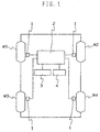
- the apparatus for alarming decrease in air-pressure detects whether the air-pressure of any of the four wheels W 1 , W 2 , W 3 , W 4 (hereinafter referred to as "W i ”) attached to a four-wheeled vehicle has decreased or not, and includes wheel speed sensors 1 of normal arrangement respectively arranged in connection with each of the tyres W i .
- Each wheel speed sensor 1 detects rotational information for a tyre, e.g. the number of rotations, the revolution speed or the angular speed. Outputs of the wheel speed sensors 1 are supplied to a control unit 2.
- a display means 3 comprising a crystal display element, plasma display element, CRT, lamp or sound generator for informing a driver of a tyre W i the air-pressure of which has decreased, and an initialising switch 4 which can be operated, for instance, by the driver.
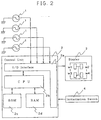
- the control unit 2 comprises a storing means for storing the rotational information of each tyre W i and relationships between right and left wheel ratios of right and left tyres of the tyres which may be of different types which have been preliminarily set to be at normal air-pressure and driving force, a calculating and processing means for calculating determined values from the rotation information of each tyre W i , and a determining means for correcting the right and left wheel ratios of the driving wheels at the time of actual running based on the relationship between the right and left wheel ratios of right and left tyres of different types and driving force and for determining decrease in internal pressure of a tyre.
- control unit 2 is composed of an I/O interface 2a required for sending/receiving signals to/from an external device, a CPU 2b which functions as a calculation centre, a ROM 2c which stores a control operation program for the CPU 2b, and a RAM 2d into which data is temporarily written and from which it is read out when the CPU 2b performs control operations.
- Right and left tyres of different types which have been set to be at normal air-pressure might, for instance, be a new tyre and a worn tyre the degree of wear of which can be 50%, or two types of tyres of which the front and rear rigidity vary, e.g. a summer tyre and a winter tyre.
- the coefficient m is obtained as a right and left wheel ratio of the right and left tyres of the following wheels (V 1 /V 2 ), and the coefficient n as a right and left wheel ratio of the right and left tyres of the driving wheels (V 3 /V 4 ).
- the right and left wheel ratios obtained at this time are averaged values of values periodically calculated under various running conditions during initialisation. Then, a determined value is calculated based on the revolution speed V1 i . This determined value is obtained form the following equation (5) in the case where the difference between two diagonal sums is set to be the determined value (DEL value).
- right and left wheel ratios due to driving force generated at the time of actual running are corrected and a decrease in internal pressure of a tyre is determined in the present invention by preliminarily storing how the right and left wheel ratios of right and left tyres of different types of the driving wheels which have been set to be at normal air-pressure vary by the influence of driving force.
- initialisation is performed at the time of exchanging a tyre in a system for determining loss of pressure based on differences in relative wheel speed of tyres, so that slip rates are calculated by sampling front and rear wheel ratios simultaneously with sampling of wheel speed data at the time of actual running, and it is then obtained how the right and left wheel ratios of tyres of different types of driving wheels vary upon influence of driving force (which is expressed by a slip rate calculated by (front and rear wheel ratio - 1)).
- V 3 V 4 A ( V 3 + V 4 V 1 + V 2 ) + B
- the right and left wheel ratios of driving wheels at the time of running can be accurately corrected since there is a preliminarily stored, for example, from initialisation under actual running performed when a tyre has been exchanged, how the right and left wheel ratios of right and left tyres of different types of driving wheels and slip rates due to driving force vary. Consequently, the accuracy of determining decrease in internal pressure of a tyre is improved and erroneous alarm or failure in alarm can be prevented.
- initialising operations are performed in order to correct differences in outer diameter of the tyres. As described earlier, these operations measure the right and left wheel ratios of tyre dynamic load radiuses at normal air-pressure.
- the right and left wheel ratios are constant, irrespective of driving force or braking force (driving force/braking force) or the revolution speed, and are corrected by the equations (1) to (4).
- the degrees of wear differ between right and left tyres of the driving wheels
- the right and left wheel ratios of the driving wheels are dependent on the magnitude of driving force/braking force.
- the system obtains the right and left wheel ratios of the driving wheels as a function of the driving force/braking force.
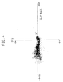
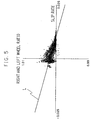
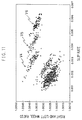
- the system performs sampling of right and left wheel ratios of wheel speeds and (front and rear wheel ratio - 1) in a second as one data, and a specified number of data are obtained. The results are shown in Figure 5.
- the determined value DEL is calculated in accordance with equation (5), compared with a set threshold, and if this is exceeded, an alarm is given.
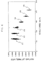
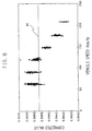
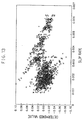
- FIG. 6 driving tests were performed with a rear wheel driving vehicle (FR vehicle) having right and left tyres of different types, namely a new tyre and a worn tyre, and the driving speed-is increased from 60 Km/hour by 30 Km/hour steps up to a speed of 210 Km/hour (V 1 to V 6 ).
- the right and left wheel ratios are substantially constant as long as the vehicle speed is not more than approximately 120 Km/hour. However, when the vehicle speed exceeds approximately 120 Km/hour, the right and left wheel ratios of the following wheels become shifted (not constant) due to the different tyres.
- the right and left wheel ratios of the following wheels are correlated as squares of the vehicle speed, as shown in Figure 6. This can be explained by the fact that tyres which differ in degrees of wear on the right and left side cause differences in centrifugal force acting on the right and left tyres since there exist differences in tread weight and thus result in a correlation of the right and left differences to a square of speed.
- the right and left wheel ratios are not dependent on the driving force (corresponding to relative slip rates) expressed as slip rates calculated from (front and rear wheel ration --1).
- the correction values for the right and left wheel ratios of the following wheels are obtained from a quadratic function for the vehicle speed in the present embodiment.
- Vnr Vnr ⁇ ( Kna ⁇ Vmean 2 + Knb )
- the correction coefficients Kna, Knb can be obtained by regressing (Kna ⁇ Vmean 2 +Knb) as a linear function of Vmean.
- the control unit 2 comprises a wheel speed sensor 1 which is a rotational information detecting means for detecting the rotational information of each tyre W i ; a storing means for storing the rotational information of each tyre W,; and relationships between right and left wheel ratios of right and left tyres of different types of following wheels which have preliminarily been made to be of normal air-pressure and vehicle speed; a calculating and processing means for calculating determined values from the rotational information of each tyre W i ; and a determining means for correcting right and left wheel ratios of following wheels at the time of actual running based on the relationship between the right and left wheel ratios of right and left tyres and vehicle speed and determining decrease in internal pressure of a tyre.
- a wheel speed sensor 1 which is a rotational information detecting means for detecting the rotational information of each tyre W i ; a storing means for storing the rotational information of each tyre W,; and
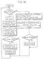
- An alarm is given when the thresholds of determined values exceed, e.g. a range of -0.1 to +0.1, based on the flowchart of Figure 14.
- the accuracy of determining decrease in internal pressure of a tyre at the time of running at a high speed can be further improved compared to Embodiment 1, and erroneous alarm or failure in alarm can be prevented.
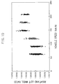
- Embodiment 1 While in Embodiment 1 relationships between right and left wheel ratios of driving wheels at straight-ahead running with tyres of normal internal pressure and driving force are stored when right and left tyres of different types are attached to the driving wheels, and the right and left wheel ratios of driving wheels are corrected by the use of the stored relationships, the relationship between right and left wheel ratios and slip rates is varied due to the vehicle speed in case the vehicle speed is not less than approximately 120 Km/hour (V 4 to V 6 ) as shown in Figure 11, and erroneous alarm or failure in alarm might undesirably occur.
- Kda ( N ⁇ Syz - Sdy ⁇ Sz ) / N ⁇ Sdy 2 - Sdy ⁇ Sdy )
- Kdb ( Sz - Kda ⁇ Sdy ) / N
- Equation (15) can be obtained as a linear combination function of a quadratic function for the vehicle speed in case the vehicle speed in which the vehicle speed with respect to the right and left wheel ratios is of zero slop and of a linear function for the driving force.
- Vdr Vdr ⁇ ( Kda ⁇ Vmean 2 + Kdb ⁇ DFR + Kdc )
- Each of the correction coefficients can be obtained from the following equations (19) to (21) employing equations (16) to (18) by performing multiple regression of Vmean 2 and the driving force (DFR) with respect to Vdr/Vdl.
- Ta ( N ⁇ Szx ⁇ Sdy 2 ⁇ Sdxy ⁇ Sdy ⁇ Sz + Sdx ⁇ Sdy ⁇ Syz - Sdx ⁇ Sdy 2 ⁇ Sz - Szx ⁇ Sdy ⁇ Sdy - N ⁇ Sdxy ⁇ Syz )
- Tb ( N ⁇ Syz ⁇ Sdx 2 + Sdxy ⁇ Sdx ⁇ Sz + Sdx ⁇ Sdy ⁇ Szx - Sdy ⁇ Sdx 2 ⁇ Sz - Syz ⁇ Sdx ⁇ Sdx - N ⁇ Sdxy ⁇ Szx )
- Tc ( N ⁇ Sdx 2 ⁇ SDY 2 - S
- the control unit 2 comprises a rotational information detecting means for detecting rotational information of each tyre W i ; a storing means for storing rotational information of each tyre W i and relationships among right and left wheel ratios of right and left tyres of different types of driving wheels which have preliminarily been made at normal air-pressure, vehicle speed and driving force; a calculating and processing means for calculating determined values from the rotational information of each tyre W i ; and a determining means for correcting right and left wheel ratios of driving wheels at the time of actual running based on the relationship among the right and left wheel ratios of right and left tyres of different types, vehicle speed and driving force and for determining decrease in internal pressure of a tyre.
- An alarm is given when the thresholds of determined values exceed, e.g. a rang of -0.1 to +0.1, based on the flowchart of Figure 14.
- the accuracy of determining decrease in internal pressure of a tyre at the time of running at high speed can be further improved compared to Embodiment 1, and erroneous alarm or failure in alarm can be prevented.
- the right and left wheel ratios of non-driven wheels and driven wheels at the time of actual running can be accurately corrected since they are preliminarily stored during initialisation performed by actually running at the time of, for instance, exchanging a tyre, how the right and left wheel ratios (relative speed ratios) of right and left tyres of different type of driving wheels and slip rates due to driving force vary, since relationships between the right and left wheel ratios (relative speed ratios) of right and left tyres of different types of following wheels and vehicle speeds are preliminarily stored, and since relationships among the right and left wheel ratios (relative speed ratios) of right and left tyres of different types of driving wheels, driving force (slip rate) and vehicle speeds are preliminarily stored. Consequently, the accuracy for determining decrease in internal pressure of a tyre can be improved, and erroneous alarm or failure in alarm can be prevented.
Landscapes
- Engineering & Computer Science (AREA)
- Mechanical Engineering (AREA)
- Measuring Fluid Pressure (AREA)
Claims (8)
- Vorrichtung zum Warnen vor einer Abnahme eines Innenluftdruckes eines Reifens auf der Basis von Rotationsinformation, die von an einem vierrädrigen Fahrzeug angebrachten Reifen erhalten wird, mit einem Rotationsinformations-Detektionsmittel zum Detektieren von Rotationsinformation von jedem Reifen und einem Berechnungs- und Verarbeitungsmittel zum Berechnen bestimmter Werte aus der Rotationsinformation von jedem Reifen;
dadurch gekennzeichnet, dass sie darüber hinaus ein Speichermittel zum Speichern der Rotationsinformation von jedem Reifen und von Beziehungen zwischen Relativgeschwindigkeitsverhältnissen von rechten und linken Reifen unterschiedlicher Typen von Rädern, die vorbereitend als auf einem normalen Luftdruck befindlich festgelegt worden sind, und ein Bestimmungsmittel zum Korrigieren von Relativgeschwindigkeitsverhältnissen von rechten und linken Reifen unterschiedlicher Typen von Rädern zu dem Zeitpunkt einer tatsächlichen Fahrt auf der Basis der gespeicherten Beziehung zwischen dem Relativgeschwindigkeitsverhältnis von rechten und linken Reifen unterschiedlicher Typen von Rädern und zum Bestimmen einer Abnahme eines Innendruckes eines Reifens umfasst. - Vorrichtung zum Warnen vor einer Abnahme eines Innenluftdruckes eines Reifens nach Anspruch 1, dadurch gekennzeichnet, dass das Bestimmungsmittel ein Relativgeschwindigkeitsverhältnis von treibenden Rädern zu dem Zeitpunkt einer tatsächlichen Fahrt auf der Basis einer vorbereitend gespeicherten Beziehung zwischen dem Relativgeschwindigkeitsverhältnis von rechten und linken Reifen unterschiedlicher Typen von treibenden Rädern und einer Antriebskraft korrigiert.
- Vorrichtung zum Warnen vor einer Abnahme eines Innenluftdruckes eines Reifens nach Anspruch 1, dadurch gekennzeichnet, dass das Bestimmungsmittel ein Relativgeschwindigkeitsverhältnis von treibenden Rädern zu dem Zeitpunkt einer tatsächlichen Fahrt auf der Basis einer vorbereitend gespeicherten Beziehung zwischen dem Relativgeschwindigkeitsverhältnis von rechten und linken Reifen unterschiedlicher Typen von treibenden Rädern, der Fahrzeuggeschwindigkeit und der Antriebskraft korrigiert.
- Vorrichtung zum Warnen vor einer Abnahme eines Innenluftdruckes eines Reifens nach Anspruch 1, dadurch gekennzeichnet, dass das Bestimmungsmittel ein Relativgeschwindigkeitsverhältnis von nicht angetriebenen oder mitlaufenden Rädern zu dem Zeitpunkt einer tatsächlichen Fahrt auf der Basis einer vorbereitend gespeicherten Beziehung zwischen dem Relativgeschwindigkeitsverhältnis von rechten und linken Reifen unterschiedlicher Typen von nicht angetriebenen oder mitlaufenden Rädern und der Fahrzeuggeschwindigkeit korrigiert.
- Verfahren zum Warnen vor einer Abnahme eines Innenluftdruckes eines Reifens auf der Basis von Rotationsinformation, die von an einem vierrädrigen Fahrzeug angebrachten Reifen erhalten wird, dadurch gekennzeichnet, dass ein Relativgeschwindigkeitsverhältnis von rechten und linken Reifen unterschiedlicher Typen von Rädern zu dem Zeitpunkt einer tatsächlichen Fahrt auf der Basis einer vorbereitend gespeicherten Beziehung zwischen dem Relativgeschwindigkeitsverhältnis von rechten und linken Reifen unterschiedlicher Typen von Rädern, die vorbereitend als auf einem normalen Luftdruck befindlich festgelegt worden sind, korrigiert wird, und eine Abnahme eines Innendruckes eines Reifens bestimmt wird.
- Verfahren zum Warnen vor einer Abnahme eines Innenluftdruckes eines Reifens nach Anspruch 5, dadurch gekennzeichnet, dass ein Relativgeschwindigkeitsverhältnis von treibenden Rädern zu dem Zeitpunkt einer tatsächlichen Fahrt auf der Basis einer vorbereitend gespeicherten Beziehung zwischen dem Relativgeschwindigkeitsverhältnis von rechten und linken Reifen unterschiedlicher Typen von treibenden Rädern und der Antriebskraft korrigiert wird.
- Verfahren zum Warnen vor einer Abnahme eines Innenluftdruckes eines Reifens nach Anspruch 5, dadurch gekennzeichnet, dass ein Relativgeschwindigkeitsverhältnis von treibenden Rädern zu dem Zeitpunkt einer tatsächlichen Fahrt auf der Basis einer vorbereitend gespeicherten Beziehung zwischen dem Relativgeschwindigkeitsverhältnis von rechten und linken Reifen unterschiedlicher Typen von treibenden Rädern, der Fahrzeuggeschwindigkeit und der Antriebskraft korrigiert wird.
- Verfahren zum Warnen vor einer Abnahme eines Innenluftdruckes eines Reifens nach Anspruch 5, dadurch gekennzeichnet, dass ein Relativgeschwindigkeitsverhältnis von nicht angetriebenen oder mitlaufenden Rädern zu dem Zeitpunkt einer tatsächlichen Fahrt auf der Basis einer vorbereitend gespeicherten Beziehung zwischen dem Relativgeschwindigkeitsverhältnis von rechten und linken Reifen unterschiedlicher Arten von nicht angetriebenen oder mitlaufenden Rädern und der Fahrzeuggeschwindigkeit korrigiert wird.
Applications Claiming Priority (6)
| Application Number | Priority Date | Filing Date | Title |
|---|---|---|---|
| JP273055/97 | 1997-10-06 | ||
| JP27305597 | 1997-10-06 | ||
| JP27305597 | 1997-10-06 | ||
| JP16173298A JP3340961B2 (ja) | 1997-10-06 | 1998-06-10 | タイヤ空気圧低下警報装置および方法 |
| JP16173298 | 1998-06-10 | ||
| JP161732/98 | 1998-06-10 |
Publications (3)
| Publication Number | Publication Date |
|---|---|
| EP0908331A2 EP0908331A2 (de) | 1999-04-14 |
| EP0908331A3 EP0908331A3 (de) | 2003-08-06 |
| EP0908331B1 true EP0908331B1 (de) | 2006-01-04 |
Family
ID=26487761
Family Applications (1)
| Application Number | Title | Priority Date | Filing Date |
|---|---|---|---|
| EP98308070A Expired - Lifetime EP0908331B1 (de) | 1997-10-06 | 1998-10-05 | Gerät und Verfahren zum Detektieren eines Druckabfalles im Reifen |
Country Status (4)
| Country | Link |
|---|---|
| US (1) | US6060983A (de) |
| EP (1) | EP0908331B1 (de) |
| JP (1) | JP3340961B2 (de) |
| DE (1) | DE69833095T2 (de) |
Families Citing this family (20)
| Publication number | Priority date | Publication date | Assignee | Title |
|---|---|---|---|---|
| JP3601347B2 (ja) * | 1999-03-05 | 2004-12-15 | 日産自動車株式会社 | 車両制御装置及び走行抵抗の測定方法 |
| US6396396B2 (en) * | 1999-12-09 | 2002-05-28 | Sumitomo Rubber Industries, Ltd. | Method for alarming decrease in tire air-pressure and apparatus used therefor |
| US6285280B1 (en) * | 2000-06-26 | 2001-09-04 | Robert Bosch Corporation | Method for detecting a deflated tire on a vehicle |
| US7161476B2 (en) | 2000-07-26 | 2007-01-09 | Bridgestone Firestone North American Tire, Llc | Electronic tire management system |
| US8266465B2 (en) | 2000-07-26 | 2012-09-11 | Bridgestone Americas Tire Operation, LLC | System for conserving battery life in a battery operated device |
| JP3475165B2 (ja) * | 2000-09-20 | 2003-12-08 | 住友ゴム工業株式会社 | タイヤ空気圧低下警報装置および方法 |
| JP2003054230A (ja) * | 2001-08-16 | 2003-02-26 | Sumitomo Rubber Ind Ltd | タイヤ空気圧低下検出方法および装置、ならびにタイヤ減圧判定しきい値の選択プログラム |
| DE10152338B4 (de) * | 2001-10-24 | 2004-11-18 | Siemens Ag | Verfahren und System zur Überwachung der Räder eines Kraftfahrzeuges |
| JP2003267012A (ja) * | 2002-01-09 | 2003-09-25 | Sumitomo Rubber Ind Ltd | タイヤ空気圧低下検出方法および装置、ならびにタイヤ減圧判定のプログラム |
| JP2003220811A (ja) * | 2002-01-30 | 2003-08-05 | Sumitomo Rubber Ind Ltd | タイヤ空気圧低下検出方法および装置、ならびにタイヤ減圧判定のプログラム |
| JP3869762B2 (ja) * | 2002-06-13 | 2007-01-17 | 住友ゴム工業株式会社 | タイヤ空気圧低下検出方法および装置、ならびにタイヤ減圧判定のプログラム |
| JP2004203214A (ja) | 2002-12-25 | 2004-07-22 | Sumitomo Rubber Ind Ltd | タイヤ空気圧低下検出方法および装置、ならびにタイヤ減圧判定のプログラム |
| US20040225423A1 (en) * | 2003-05-07 | 2004-11-11 | Carlson Christopher R. | Determination of operational parameters of tires in vehicles from longitudinal stiffness and effective tire radius |
| EP1547828B1 (de) * | 2003-11-25 | 2010-10-20 | Sumitomo Rubber Industries Limited | Verfahren und Gerät zum Detektieren eines Druckabfalls in Reifen, und Programm für die Beurteilung eines Druckabfalls in Reifen |
| JP2005205977A (ja) * | 2004-01-21 | 2005-08-04 | Sumitomo Rubber Ind Ltd | タイヤ空気圧低下検出方法および装置、ならびにタイヤ減圧判定のプログラム |
| JP4159541B2 (ja) * | 2004-12-24 | 2008-10-01 | 住友ゴム工業株式会社 | タイヤ空気圧低下検出方法および装置 |
| JP4536089B2 (ja) * | 2007-07-20 | 2010-09-01 | 住友ゴム工業株式会社 | タイヤ空気圧低下検出方法および装置、ならびにタイヤ減圧判定のプログラム |
| WO2009101841A1 (ja) | 2008-02-14 | 2009-08-20 | Sumitomo Rubber Industries, Ltd. | 空気圧低下検出方法におけるパラメータの設定方法 |
| US20170028795A1 (en) * | 2015-07-28 | 2017-02-02 | GM Global Technology Operations LLC | Indication of vehicle status using light |
| US12479417B2 (en) * | 2023-05-17 | 2025-11-25 | GM Global Technology Operations LLC | System and method for tire blowout detection using wheel speeds |
Family Cites Families (11)
| Publication number | Priority date | Publication date | Assignee | Title |
|---|---|---|---|---|
| JP2746341B2 (ja) * | 1993-11-02 | 1998-05-06 | 本田技研工業株式会社 | 車輪減圧判定装置 |
| JPH07137512A (ja) | 1993-11-17 | 1995-05-30 | Sumitomo Electric Ind Ltd | タイヤ空気圧低下検出装置における回転角速度補正方法 |
| US5578984A (en) * | 1993-11-04 | 1996-11-26 | Sumitomo Electric | Tire air pressure reduction detecting method and apparatus |
| JPH07260810A (ja) * | 1994-03-18 | 1995-10-13 | Honda Motor Co Ltd | 車輪速度補正装置 |
| JP2749784B2 (ja) * | 1994-11-21 | 1998-05-13 | 住友電気工業株式会社 | 旋回半径計算方法および旋回半径計算装置 |
| US5604307A (en) * | 1995-02-01 | 1997-02-18 | Sumitomo Rubber Industries, Ltd. | Tire pressure drop alarm device sensing partial travel on irregular road surface |
| JP3624446B2 (ja) * | 1995-02-17 | 2005-03-02 | 日産自動車株式会社 | タイヤ内圧低下検出装置 |
| JP3175552B2 (ja) * | 1995-08-04 | 2001-06-11 | 株式会社デンソー | タイヤ空気圧推定装置 |
| JP3509330B2 (ja) * | 1995-10-11 | 2004-03-22 | 本田技研工業株式会社 | 車両の車輪減圧判定装置 |
| KR100312875B1 (ko) * | 1996-04-15 | 2001-12-12 | 사이토 나오토 | 타이어의 공기압 저하 검출방법 및 장치 |
| US5764137A (en) * | 1996-12-09 | 1998-06-09 | Chrysler Corporation | System and method for diagnosing loss of pressure in tires of a vehicle |
-
1998
- 1998-06-10 JP JP16173298A patent/JP3340961B2/ja not_active Expired - Lifetime
- 1998-10-05 DE DE69833095T patent/DE69833095T2/de not_active Expired - Lifetime
- 1998-10-05 EP EP98308070A patent/EP0908331B1/de not_active Expired - Lifetime
- 1998-10-06 US US09/166,965 patent/US6060983A/en not_active Expired - Lifetime
Also Published As
| Publication number | Publication date |
|---|---|
| US6060983A (en) | 2000-05-09 |
| EP0908331A2 (de) | 1999-04-14 |
| EP0908331A3 (de) | 2003-08-06 |
| JPH11170828A (ja) | 1999-06-29 |
| DE69833095T2 (de) | 2006-08-31 |
| JP3340961B2 (ja) | 2002-11-05 |
| DE69833095D1 (de) | 2006-03-30 |
Similar Documents
| Publication | Publication Date | Title |
|---|---|---|
| EP0908331B1 (de) | Gerät und Verfahren zum Detektieren eines Druckabfalles im Reifen | |
| EP0652121B1 (de) | Verfahren und Vorrichtung zum Erkennen von Reifendruckverminderung | |
| EP1167086B1 (de) | Gerät und Verfahren zum Detektieren eines Druckabfalls im Reifen | |
| EP0897816B1 (de) | Gerät und Verfahren zum Warnen vor Reifendruckverlust | |
| EP1880875B1 (de) | Verfahren, Vorrichtung und Programm zur Warnung im Fall einer Abnahme des Luftdrucks eines Reifens | |
| EP0647535B1 (de) | Verfahren zum Erkennen eines leeren Reifens an einem Fahrzeug | |
| EP1190874B1 (de) | Gerät und Verfahren zum Detektieren eines Druckabfalls im Reifen | |
| EP1352765B1 (de) | Verfahren und Gerät zum Detektieren eines Druckabfalls im Reifen und Programm zur Beurteilung des Druckabfalls im Reifen | |
| EP1145875B1 (de) | Gerät und Verfahren zum Detektieren eines Druckabfalls im Reifen | |
| US7032442B2 (en) | Method and apparatus for detecting decrease in tire air-pressure and program for judging decompression of tire | |
| EP0642427B1 (de) | Verfahren zum erkennen eines leeren reifens an einem fahrzeug | |
| EP0970823A2 (de) | Verfahren und Gerät für die Identifizierung von Reifen | |
| EP1127720B1 (de) | Vorrichtung und Verfahren zum Detektieren eines Druckabfalls im Reifen | |
| US20020021212A1 (en) | Apparatus and method for alarming decrease in tire air-pressure | |
| EP1332895B1 (de) | Methode und Apparat um ein Abfallen des Reifenluftdrucks zu erkennen | |
| US6529851B1 (en) | Method for detecting decrease in tire air-pressure and apparatus used therefor | |
| EP1215057B1 (de) | Gerät und Verfahren zum Detektieren eines Druckabfalls im Reifen | |
| US6756891B2 (en) | Method and apparatus for detecting decrease in tire air-pressure, and selecting program for the thresholds for judging decompression of tire | |
| JP2000190719A (ja) | タイヤ空気圧低下警報方法および装置 | |
| EP0579446B1 (de) | Verfahren zum Erkennen eines leeren Reifens an einem Fahrzeug | |
| US7395145B2 (en) | Apparatus and method for calculating initial correction coefficient, and program for calculating initial correction coefficient | |
| EP1454773B1 (de) | Verfahren und Vorrichtung zum Detektieren eines Druckabfalls im Reifen | |
| EP1798078B1 (de) | Vorrichtung, Verfahren und Programm zur Alarmierung einer Reifendruckabweichung | |
| JP3626076B2 (ja) | タイヤ空気圧低下警報装置および方法 |
Legal Events
| Date | Code | Title | Description |
|---|---|---|---|
| PUAI | Public reference made under article 153(3) epc to a published international application that has entered the european phase |
Free format text: ORIGINAL CODE: 0009012 |
|
| AK | Designated contracting states |
Kind code of ref document: A2 Designated state(s): AT BE CH CY DE DK ES FI FR GB GR IE IT LI LU MC NL PT SE |
|
| AX | Request for extension of the european patent |
Free format text: AL;LT;LV;MK;RO;SI |
|
| PUAL | Search report despatched |
Free format text: ORIGINAL CODE: 0009013 |
|
| AK | Designated contracting states |
Designated state(s): AT BE CH CY DE DK ES FI FR GB GR IE IT LI LU MC NL PT SE |
|
| AX | Request for extension of the european patent |
Extension state: AL LT LV MK RO SI |
|
| 17P | Request for examination filed |
Effective date: 20030915 |
|
| AKX | Designation fees paid |
Designated state(s): DE FR GB |
|
| 17Q | First examination report despatched |
Effective date: 20040407 |
|
| GRAP | Despatch of communication of intention to grant a patent |
Free format text: ORIGINAL CODE: EPIDOSNIGR1 |
|
| GRAS | Grant fee paid |
Free format text: ORIGINAL CODE: EPIDOSNIGR3 |
|
| GRAA | (expected) grant |
Free format text: ORIGINAL CODE: 0009210 |
|
| AK | Designated contracting states |
Kind code of ref document: B1 Designated state(s): DE FR GB |
|
| REG | Reference to a national code |
Ref country code: GB Ref legal event code: FG4D |
|
| REF | Corresponds to: |
Ref document number: 69833095 Country of ref document: DE Date of ref document: 20060330 Kind code of ref document: P |
|
| ET | Fr: translation filed | ||
| PLBE | No opposition filed within time limit |
Free format text: ORIGINAL CODE: 0009261 |
|
| STAA | Information on the status of an ep patent application or granted ep patent |
Free format text: STATUS: NO OPPOSITION FILED WITHIN TIME LIMIT |
|
| 26N | No opposition filed |
Effective date: 20061005 |
|
| PGFP | Annual fee paid to national office [announced via postgrant information from national office to epo] |
Ref country code: GB Payment date: 20150930 Year of fee payment: 18 |
|
| REG | Reference to a national code |
Ref country code: FR Ref legal event code: PLFP Year of fee payment: 19 |
|
| GBPC | Gb: european patent ceased through non-payment of renewal fee |
Effective date: 20161005 |
|
| PG25 | Lapsed in a contracting state [announced via postgrant information from national office to epo] |
Ref country code: GB Free format text: LAPSE BECAUSE OF NON-PAYMENT OF DUE FEES Effective date: 20161005 |
|
| REG | Reference to a national code |
Ref country code: FR Ref legal event code: PLFP Year of fee payment: 20 |
|
| PGFP | Annual fee paid to national office [announced via postgrant information from national office to epo] |
Ref country code: FR Payment date: 20170918 Year of fee payment: 20 |
|
| PGFP | Annual fee paid to national office [announced via postgrant information from national office to epo] |
Ref country code: DE Payment date: 20170927 Year of fee payment: 20 |
|
| REG | Reference to a national code |
Ref country code: DE Ref legal event code: R071 Ref document number: 69833095 Country of ref document: DE |