EP0906885B1 - Fadenbremse - Google Patents
Fadenbremse Download PDFInfo
- Publication number
- EP0906885B1 EP0906885B1 EP98116792A EP98116792A EP0906885B1 EP 0906885 B1 EP0906885 B1 EP 0906885B1 EP 98116792 A EP98116792 A EP 98116792A EP 98116792 A EP98116792 A EP 98116792A EP 0906885 B1 EP0906885 B1 EP 0906885B1
- Authority
- EP
- European Patent Office
- Prior art keywords
- thread
- clip
- brake according
- thread brake
- bearing
- Prior art date
- Legal status (The legal status is an assumption and is not a legal conclusion. Google has not performed a legal analysis and makes no representation as to the accuracy of the status listed.)
- Expired - Lifetime
Links
Images

Classifications
-
- D—TEXTILES; PAPER
- D04—BRAIDING; LACE-MAKING; KNITTING; TRIMMINGS; NON-WOVEN FABRICS
- D04B—KNITTING
- D04B15/00—Details of, or auxiliary devices incorporated in, weft knitting machines, restricted to machines of this kind
- D04B15/38—Devices for supplying, feeding, or guiding threads to needles
- D04B15/48—Thread-feeding devices
-
- B—PERFORMING OPERATIONS; TRANSPORTING
- B65—CONVEYING; PACKING; STORING; HANDLING THIN OR FILAMENTARY MATERIAL
- B65H—HANDLING THIN OR FILAMENTARY MATERIAL, e.g. SHEETS, WEBS, CABLES
- B65H59/00—Adjusting or controlling tension in filamentary material, e.g. for preventing snarling; Applications of tension indicators
- B65H59/10—Adjusting or controlling tension in filamentary material, e.g. for preventing snarling; Applications of tension indicators by devices acting on running material and not associated with supply or take-up devices
- B65H59/20—Co-operating surfaces mounted for relative movement
- B65H59/22—Co-operating surfaces mounted for relative movement and arranged to apply pressure to material
-
- D—TEXTILES; PAPER
- D04—BRAIDING; LACE-MAKING; KNITTING; TRIMMINGS; NON-WOVEN FABRICS
- D04B—KNITTING
- D04B15/00—Details of, or auxiliary devices incorporated in, weft knitting machines, restricted to machines of this kind
- D04B15/38—Devices for supplying, feeding, or guiding threads to needles
- D04B15/44—Tensioning devices for individual threads
-
- B—PERFORMING OPERATIONS; TRANSPORTING
- B65—CONVEYING; PACKING; STORING; HANDLING THIN OR FILAMENTARY MATERIAL
- B65H—HANDLING THIN OR FILAMENTARY MATERIAL, e.g. SHEETS, WEBS, CABLES
- B65H2701/00—Handled material; Storage means
- B65H2701/30—Handled filamentary material
- B65H2701/31—Textiles threads or artificial strands of filaments
-
- B—PERFORMING OPERATIONS; TRANSPORTING
- B65—CONVEYING; PACKING; STORING; HANDLING THIN OR FILAMENTARY MATERIAL
- B65H—HANDLING THIN OR FILAMENTARY MATERIAL, e.g. SHEETS, WEBS, CABLES
- B65H59/00—Adjusting or controlling tension in filamentary material, e.g. for preventing snarling; Applications of tension indicators
- B65H59/10—Adjusting or controlling tension in filamentary material, e.g. for preventing snarling; Applications of tension indicators by devices acting on running material and not associated with supply or take-up devices
- B65H59/20—Co-operating surfaces mounted for relative movement
- B65H59/22—Co-operating surfaces mounted for relative movement and arranged to apply pressure to material
- B65H59/225—Tension discs
Definitions
- the invention relates to a thread brake with two resiliently pressed against each other by load means disc or plate-shaped brake elements, between which can be carried out at least one thread to be braked and of which at least one braking element is a central one Has opening.
- disc or plate thread brakes are in various forms in textile technology in use. Particularly advantageous, modern constructions are described, for example, in DE 41 04 663 C1 and in DE 43 01 507 C2, both to the applicant decline.
- the latter of these two publications is the generic term of claim 1. They have pin-shaped storage means throughout on through the central opening at least one Braking element are arranged and on which at least this one braking element is rotatably mounted.
- the diameter a bearing pin forming the pin-shaped bearing means is much smaller than the diameter of the middle Opening the brake elements so that they swing freely are hung from the bearing pin.
- pin-shaped storage means that are in the form of a Bolts are formed, the diameter of which is only slight is smaller than the opening diameter of the brake elements (compare, for example, FIG. 5 of DE 41 04 663 C1), the brake elements are provided with plastic bearing bushes are their storage conditions on the bolt or a ceramic bearing bush pushed onto this improve.
- the brake elements are elastic against each other oppressive burden means are either after conventional type compression springs or there are too permanent magnetic rings are used for this purpose cup-shaped, made of ferromagnetic material existing brake elements are inserted.
- Thread guide means usually provided at least partially directly on the mounting means which the bearing pin or bolt for carry the braking elements.
- the arrangement is mostly hit such that the bearing pin or pin on the Bracket is overhung.
- the braking elements such as mentioned, oscillating on a small diameter bearing pin are suspended, the braking elements at a distance assigned lateral stop elements, which otherwise limit and prevent free movement in the axial direction, that the braking elements are released from their bearing means.
- the holding means with which the thread brake, for example. is attached to the housing of a thread delivery device, are consistently designed to be relatively expensive applies in particular if the thread brake with a Vibration generator cooperates that the Brake elements set in oscillatory movements, the are mainly directed transversely to the bearing axis (DE 41 04 663 C1) or in a direction perpendicular to it act (DE 44 09 450 C2). Because of the braking elements or their bearing means vibrated the lint deposits that otherwise occur, Soiling, etc., originating from difficult to process Yarns can be largely prevented. The The measure has therefore proven itself in practice proven.
- Thread brakes of the aforementioned type are fundamental Bulk item, which means manufacturing cost vital to the economic Success comes. They also have to be easy to maintain and in particular, to be cleaned, what usually through Blow off by means of a compressed air jet. there should be avoided that the braking elements from their Free storage materials or that have blown off Dirt particles, lint and the like in corners or blind spots of mounting elements, bearing parts, etc. accumulate the thread brake and thus in the long run Endanger operational safety.
- the object of the invention is therefore a thread brake to create oneself with simple, inexpensive Construction due to few dirt deposits distinguished and easy cleaning, as well as necessary disassembly and assembly of your parts allowed, while at the same time a perfectly even Braking of the thread guaranteed over long operating periods is.
- the thread brake according to the invention the features of the characterizing part of claim 1 on.
- the holder means on the new thread brake for which the disc or plate-shaped brake elements bearing, pin-shaped bearing means essentially one U-shaped bracket with two spaced apart on both sides of the brake elements trending thighs on a preferred Embodiment is a one-piece wire bent part.
- the pin-shaped bearing means are on this bracket a bearing part which preferably accommodates them on both sides attached that connected to the stirrup legs or on this is trained.
- This bearing part can be in one preferred embodiment in the form of an essentially U-shaped frame formed and made of plastic his.
- the bracket can be two parallel to each other Have bracket sections with which he in a receiving part is stored at a suitable location on a Machine frame or the like but also on the housing a thread delivery device can be attached.
- the Temple sections can be moved longitudinally in the receiving part be stored, which is particularly important is when at least one of the bracket sections for coupling with a back and forth oscillating motion of the bracket issuing vibration generating device is set up. In this way, as already mentioned, effectively prevents the deposition of fluff, etc. become.
- this can be the pin-shaped bearing means receiving bearing part designed to be removable from the bracket so that the bearing means together with the bearing part to be able to exchange.
- the bearing part can the bracket can also be arranged adjustable, for example To facilitate cleaning of the thread brake or around the To change thread travel.
- the bearing part as a U-shaped Frame formed, so the frame on the bracket between an operating position and a folded down position Position pivotable and in the operating position on the Bracket designed to be lockable.
- the correct position on the bracket in the operating position found frame only needs to be folded down be accessible to the pin-shaped storage means to make them blown off on all sides or otherwise can be cleaned.
- the pin-shaped storage means on the frame i.e. more generally on the bearing part, releasably attached, so they can with the frame folded down simply removed and replaced.
- the thread brake can also be designed so that the whole frame with the bearing means and the brake elements can be replaced without the bracket or others Parts of the thread brake are removed or disassembled would. Folding down and, if necessary, removing the Framework, as well as the exchange of storage resources done without tools.
- the bearing pins a much cheaper support the pin-shaped storage means guaranteed. This allows it with straight bearing pins of relatively small diameter to find the end of it without also having to Vibration exposure by a vibration generator accepted an increased risk of breakage should be. Since these bearing pins usually consist of one hard material, for example ceramic, hard material and the like exist and are relatively expensive achieve a significant price advantage in this way. Other developments of the new thread brake are the subject of subclaims.
- the new thread brake is particularly suitable for use suitable for a thread delivery device that with a Housing, a thread delivery drum rotatably mounted on the housing and one connected to the thread delivery drum Drive device, as well as arranged on the housing Thread guide means is formed.
- the thread guide serve the one of a thread supply, for example Spool coming to be supplied to a thread consumer Feed the thread to the thread delivery drum on the input side or from this on the output side the thread to the thread consumer to lead away.
- a thread delivery device is on the housing on the thread inlet side a thread brake according to the invention arranged.
- the bracket two mutually parallel bracket sections with which it is mounted in a receiving part can the parallel bracket sections directly in the Housing or in a part connected to this, for example. the receiving part be stored.
- the thread delivery device with a vibration generating device housed in the housing equipped it follows with the thread brake on the housing immediately a coupling of the bracket with this vibration generating device.
- at least one of the Strap sections for coupling with the one back and forth Vibration generating device which gives rise to the oscillating movement set up.
- one of the bracket sections with it elastic to a predetermined End position for pressing return spring means be loaded so that it is sufficient that the bracket section on a cam or pusher of the vibration generating device supports without being form-fitting to have to be coupled.
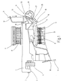
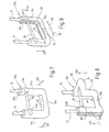
- the thread delivery device shown in Figure 1 is known in its basic structure (compare For example, Figure 1 of DE 43 01 507 C2). It has a housing 1 on that by means of a molded holder 2 and a Clamping screw 3 on a support ring indicated at 4, For example, a circular knitting machine can be attached.
- the housing is vertical in the position of use, through shaft 5 rotatably mounted.
- the wave is on its lower end with one below the housing 1 arranged and designed in the form of a rod cage Thread delivery drum 6 rotatably connected. She is wearing its upper end one rotatably via a coupling 7 couplable pulley 8, the drive device forms and over which the yarn delivery drum 6 from one Endless toothed belt or perforated belt, not shown or the like can be set in rotation.
- Thread brake 9 On the opposite end of the holder 2 Housing 1 is a thread brake 9, the two Identical, essentially disc-shaped brake plates 10, between which a thread to be braked 11 passes through.
- the thread path extends from one thread bobbin not shown by a on the Housing 1 fastens thread eyelet 12, a knot catcher 13 and the thread brake 9 to a base or Receiving part 14 provided via an integrally formed arm 15 Thread inlet eye 16, from the thread 11 on the input side runs onto the thread delivery drum 6.
- Thread delivery drum 6 On the Thread delivery drum 6, the thread 11 forms a storage roll 17, from which it is attached to the housing 1 via a Thread outlet eyelet 18 runs to the thread consumer.
- the thread brake 9 has a one-piece bent wire part trained, substantially U-shaped bracket 19 on which the holding means for the brake discs or plate 10 and their bearing means in the form of a cylindrical Bearing pin 20 forms.
- the bracket 19 has two legs 21 running parallel to each other one end through a crosspiece 22 with each other are connected, each including a right angle to the bracket legs 21.
- On at their other end are the two bracket legs 21 each via a bend 23 of approx. 30 ° and intermediate appropriately designed intermediate sections 24 with two straight bracket sections 25 parallel to one another connected.
- the parallel bracket sections 25 based on the in the Position of use horizontal crossbar 22, in different Height and close the web 22 and the two bracket legs 21 containing imaginary level an angle of approx. 30 °.
- the bracket sections 25 can also optionally with the intermediate sections 24, are at the same level, just a few possible arrangements to mention.
- bracket 19 With its two parallel bracket sections 25 is the bracket 19 in the housing-shaped base or receiving part 14 mounted longitudinally displaceable, as is the case in particular can be seen from Figure 2.
- 14 points two from the front to the back continuous, cylindrical bearing bores 26, in which the bracket sections 25 with in the use position horizontal alignment are guided longitudinally.
- the straight bracket sections 25 are both in height ( Figure 2) and laterally offset from each other ( Figure 5) arranged.
- the overhead bracket section 25 supports its over the back of the base or receptacle 14 protruding end an existing plastic, in Essentially in the form of a cylindrical cap 27 formed coupling part for a in the housing 1st arranged vibration generator, not shown, only one of them in FIG indicated by an arrow 28, back and forth Movement executing drive stamp 29 illustrated is.
- the drive stamp 29 is from one to the shaft 5 the thread delivery device according to FIG. 1, actuated cam, not shown, with which it engages stands.
- the base or receiving part 14 is one compression spring 30 surrounding the upper straight bracket section 26 arranged, which is against an axial spring abutment 31st is supported and endeavors, the coupling piece 27 in plant to hold on the drive stamp 29.
- the compression spring 30 therefore forms return spring means.
- the lower straight bracket section 25 projects, for example the rear of the base or receiving part 14 at 31 something, as indicated by dashed lines in Fig. 2. It is located on the housing 1 base or Receiving part 14 on part of the metallic housing 1 and thus causes electrical grounding of the metallic Bügels 19. Alternatively or in addition to Improvement of the earthing conditions of the bracket 19 also an earth spring (not shown) against the housing 1 press on, and / or the base 14 and / or the cap 27 consists of an electrically conductive material.
- a fastening screw indicated at 32 from the front of the base or receptacle 14 can be actuated.
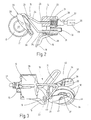
- FIG. 4 On the normal shown in Figure 2 Operating position with the vertical at an angle of approx. 30 ° inclusive, lying on a common level parallel leg 21 of the bracket 19 is a bearing part in Shape of a plastic, essentially U-shaped frame 33 in which the bearing pin 20 for the brake discs 10 at both ends is held, as can be seen in particular from FIG. 4.
- the frame 33 has two mutually parallel, spaced apart frame legs 34, which by an integrally formed frame web 35 at one end are connected.
- the two parallel frame legs 34 are facing the viewer in FIG Inside each with a gutter-shaped Well 36 formed in the vicinity of the free One end of the frame leg protrudes 37.
- the Lugs 37 are on the groove-shaped recesses 36th delimiting on the side of the U-shaped opening of the frame 33 Wall 38 formed. They serve the Frame 33 in the operating position with the legs 21 of the Bracket 19 releasably latch, as is still the case will be explained.
- the frame web 35 is on the outside with a molded bearing shell or claw 39 provided For example, in Fig. 2, 4 is visible and the on the bracket 19 mounted frame 33 elastically engages the crossbar 22, so that the frame 33 is pivotable on the web 22 is stored.
- the bearing shell or claw 39 is there resiliently designed such that the frame 33 overcoming the snap connection formed by her can simply be removed from the bracket 19.
- the frame web 35 On its inside facing the bearing pin 20 is the frame web 35 as a support or support cushion 40 trained for the brake discs or plates 10.
- the frame leg 35 can, for example, inside be provided with a wear-resistant coating.
- one made of wear-resistant Material existing pen or a corresponding one Molding is used in the frame 33, the forms the support or support cushion 40.
- the conditions of use also include cases where a particularly wear-resistant training this in the Rule the entire space between the two frame legs 34 engaging support or support cushion 40 dispensed with becomes.
- the hardened steel, possibly with a wear-resistant coating, made of ceramic or one suitable hard material, thin, cylindrical Bearing pin 20 is on its one, lower in Figure 4 End inserted into a bearing bore 41 which in the Inner wall 38 is formed.
- the bearing pin 20 is in one on the associated side Frame leg 34 provided to the gutter-like Recess 36 open bearing half shell 43 added, which is molded onto the frame leg 34.
- the depth of the Bearing half shell 43 is chosen such that the used bearing pin 20 with its lateral surface somewhat protrudes over the bottom of the groove-shaped recess 36.
- the Bearing pin 20 can also be made of non-conductive material, for example Ceramics exist, which should be mentioned for the sake of order.
- the two brake actuators 10 are on the bearing pin 20 freely suspended. You are in for this purpose in particular from FIGS. 5, 6 each with a central, cylindrical, continuous Opening 44 formed, the diameter of which many times over is larger than the diameter of the bearing pin 20th The diameter ratio is typically about 6: 1 and more.
- the bowl-shaped cambered cross section Brake plate 10 can along the edge of the Opening 44 each formed with a cylindrical lip Hub 45 may be designed to withstand the stress the brake plate 10 and the bearing pin 20 to reduce and cutting the brake plate into the bearing pin 20 to prevent.
- the edges of the Opening 44 in each of the brake actuators 10 also by one used hub ring made of plastic or a suitable bearing pairing with the bearing pin 20 resulting Material can be edged, as is shown in FIG. 10 will be explained.
- the size of the loading force determines the braking effect on the thread running through.
- the two frame legs 34 in the assembled state in considerable lateral distance from the two brake actuators 10.
- the two brake plates 10 resting against each other are therefore considerable in the axial direction Length of the bearing pin 2C freely movable.
- the frame 33 is on the used bearing pin 20 hanging brake actuators 10 with its bearing shell or claw 39 on the horizontal Web 22 of bracket 19 clipped on. Besides, he's around Axis of the web 22 folded up so far that the two Leg 21 in the groove-shaped recesses 36 of the Frame legs 34 are included and the frame 33 with the legs 21 is locked over the locking lugs 37.
- the Thread brake thus has that shown in Figures 1, 2 State in which the between the brake actuators 10 continuous thread 11 in the by the attraction the permanent magnet rings 46 given the amount evenly braked becomes.
- each other Brake actuator 10 of which around the bearing pin 20 or one not shown in the drawing by the Openings 44 of the brake discs 10 extending and in the Frame legs 34 held deflected thread deflecting pin Thread 11 driven frictionally, so that it is a perform a common rotational movement around the bearing pin 20.
- This orbital movement is a wobbling movement in the axial direction superimposed, since, as mentioned, the two brake actuators 10 have no firm lateral guidance. On this ensures that the thread 11 is not in can cut the braking surfaces of the brake plate 10, but that the braking surfaces over their entire circumference progressively engage the thread.
- bracket 19 is over the drive stamp 29 of the vibration generating device vibrating movement issued, under whose Impact of the support points on the opening edge of the Brake actuator 10 on the bearing pin 20 continuously change, so that the brake plate 10 an irregular Carry out movement that the deposit of fluff and the like prevented.
- the bearing pin 20 at one end of the bearing half-shell 43 pushed up out so that he are pulled axially out of the bearing bore 41 can. Since the frame 33 is made of plastic and in unfolded state not by the bracket legs 21 is reinforced, it is elastically deformable so that the described disassembly of the bearing pin 20 easily possible is. A new bearing pin 20 can be reversed be inserted again.
- the arrangement could also be made in such a way that the bearing pin 20 from the frame 33 directly axially is extractable by following it in at least one outside opening bearing bore 41 is supported.
- the bearing pin 20 would then be in its operating position in frame 33 by a locking mechanism, such as in the form of a Locking mechanism or through partial training as a threaded bolt secured.
- a locking mechanism such as in the form of a Locking mechanism or through partial training as a threaded bolt secured.
- Other embodiments that the serve the same purpose are conceivable.
- the two are Bow leg 21 of the U-shaped wire bracket 19a each an eyelet 47 is bent, the cylindrical bearing bore 41 limited.
- the two eyelets 47 are in alignment their bearing bores 41, in which the bearing pin 20th is plugged in.
- the bearing pin 20 is on both sides clamped elastically by the ring eyelets 47. Erforderlichefalls it can be located in the area of at least one bearing bore 41 also a recess, for example in the form of a circumferential one Rastnut, have to additionally or alternatively a form-fitting connection with the respective To produce stirrup legs 21.
- the bearing bore 41 each completely looping eyelets 47
- the bracket legs 21st also be curved so that they have ⁇ -shaped eyelets 47a, as illustrated in Figure 6b, right representation is.
- the bow legs 21 will be loop-shaped.
- the ring eyelets 47 and the eyelets 47a can also be clipped onto the respective stirrup leg 21 and there hook-shaped held frictionally Bracket claw 48 occur, as shown in Figure 6b, left Figure is shown.
- the preferably made of plastic manufactured claws 48 are the end of the Bearing pin 20 attached. They reach around with their jaws 49 the respective stirrup leg 21 on which it is frictionally engaged, are kept immovable.
- one straight bracket section 25 by the compression spring 30 ( Figure 2) in elastic contact with the actuating plunger 29 (or an actuating cam) of the vibration generating device held.
- the coupling part designed as a plastic cap 27 serves the coupling part designed as a plastic cap 27.
- the compression spring 30 it would also be conceivable, the resetting of the bracket 19 or the pressure whose bracket section 25 on the drive tappet 29 to achieve that that the bracket 19 forming Bent wire part with a corresponding elastic prestress is trained.
- positively driven embodiments with two support points of this bent wire part the drive stamp 29 or on the drive cam are possible. Such a variant is indicated in FIG. 6.
- the Temple sections 25 are approximately at right angles to one another at 470 assigning turned. Between the spaced bent bracket parts 470 could, for example Drive stamp or tappet 26 coupled.
- the one-piece, substantially U-shaped frame 33a with a to the back opening, all-round, gutter-shaped Recess 36a formed over the Frame leg 34a and the frame web 35a extends.
- the Frame 33a is through the appropriate dimensioning of the recess 36a on the bracket legs 21 and the bracket web 22 jammed. Overall, he can decrease to the front are, as indicated by the two arrows 480 is.
- the bearing pin 20 is in the frame 33a, similar to in Figure 4.
- a bearing approach and the bearing half shell are designated 42a and 43a.
- FIG. 8 is how by the way, in all embodiments - the frame 33b Made of plastic. His two frame legs 34b and the frame web 35b are each one in the plane of the two stirrup legs 21 lying and towards the outside open, groove-shaped recess 36b formed in the the bracket legs 21 are. In this way it is possible the whole frame 33b in the direction of arrows 490 to move the stirrup legs 21, for example by the operating conditions to change the thread brake.
- the Frame 33b is on the temple legs 21 in its respective Position held by friction.
- the bearing pin 20 is in this case one end in its own, the assigned U-shaped arms 21 encompass and friction with this coupled leg section 340b supported, possibly with the leg 21 also can be locked.
- the bearing pin 20 At its other end is the bearing pin 20 in a groove-like recess open on one side 50 of the associated frame leg 34 recorded and in it locks or jams.
- the bearing pin 20th folded out around the left leg 21 as by an arrow 51 is indicated. He can then from his Leg section 340b are pulled out.
- An actuating tab 52 formed on the frame 33b allows the displacement of the frame 33b in the sense of Arrows 490.
- the frame 33c formed in two parts.
- the frame legs 34c and the Frame web 35c are with a continuous, channel-shaped Provide recess 36c, which corresponds to that of the two stirrup legs 21 limited space towards each other open assigning.
- the whole frame 33c can therefore in Direction of arrows 53 downward on legs 21 moved or subtracted from them entirely.
- Optional can also the two frame legs 34c, the along a parting line 55 in the frame web 35c from one another are separated, laterally subtracted from the legs 21 become. This is indicated by two arrows 56.
- the Support of the bearing pin 20 on the frame legs 34c is solved similarly as in Figure 4. Corresponding parts are provided with corresponding reference symbols.
- the support or support pad 40 for the brake discs 10 not illustrated in detail. It can be similar be designed as in the frame 33 of Figure 4. It in any case serves the brake actuator 10 in operation limit their outer circumference radially in their path of movement.
- the brake actuators 10 hanging on the bearing pin 20 are in their operating position shown in Figure 2 on the bottom of the support or support cushion 40 from which they wobble in the course of their irregular Rotational movement more or less often during operation take off.
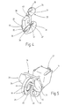
- embodiment a) are on the brake discs or plate 10 consisting of a suitable plastic clipped annular caps 60, with their all-round protruding edge areas 61, 62 the brake plate 10 on the outer circumference and along the circumference of the Overlap opening 44 so that they on the brake actuators 10 are locked.
- the caps 60 cover the cavity the cambered brake actuator 10 in the illustrated Way, while they the permanent magnet rings 46th fix in the correct position so that additional gluing, etc. is generally no longer required.
- the edge 62 bordering the opening 44 forms at the same time a substantially tubular hub, optionally is arched in cross section. To this This results in particularly favorable storage conditions the brake actuator 10 on the bearing pin 20th
- annular disk-shaped inside Mold lip 63 as shown in the illustration b) shows.
- the ring-shaped lips 63 result a small axial width of the bearing surface and thus a increased surface pressure. This can be an advantage if it must be expected that the bearing pin 20 sizing or other resinous or sticky deposits build up.
- FIG Figure c illustrates the washer-shaped Lip also in the form of an annular disc 63a be placed on the permanent magnet ring 46a, the is provided with an annular shoulder 64 for this purpose.
- the permanent magnet rings 46a are with the brake actuators 10 glued, the washers 63a each between its edge and the ring shoulder 64 of the corresponding Permanent magnet rings 46a are inserted.
- Cover 65 can also have an annular disk-shaped lip 65a of a small thickness, which is the hub of the brake actuators 10 forms, so that there are similar storage conditions as in Figures b) and c).
- the invention is not is limited to embodiments in which the Brake actuator 10 oscillating on a thin bearing pin 20 are hung. It can also be used for thread brakes, where the brake plate on a bearing pin or -pin are only rotatably supported with play.
Landscapes
- Engineering & Computer Science (AREA)
- Textile Engineering (AREA)
- Braking Arrangements (AREA)
- Tension Adjustment In Filamentary Materials (AREA)
- Spinning Or Twisting Of Yarns (AREA)
- Knitting Machines (AREA)
- Clamps And Clips (AREA)
- Portable Nailing Machines And Staplers (AREA)
Applications Claiming Priority (2)
| Application Number | Priority Date | Filing Date | Title |
|---|---|---|---|
| DE19743573 | 1997-10-02 | ||
| DE19743573A DE19743573A1 (de) | 1997-10-02 | 1997-10-02 | Fadenbremse |
Publications (3)
| Publication Number | Publication Date |
|---|---|
| EP0906885A2 EP0906885A2 (de) | 1999-04-07 |
| EP0906885A3 EP0906885A3 (de) | 2000-10-25 |
| EP0906885B1 true EP0906885B1 (de) | 2003-04-16 |
Family
ID=7844391
Family Applications (1)
| Application Number | Title | Priority Date | Filing Date |
|---|---|---|---|
| EP98116792A Expired - Lifetime EP0906885B1 (de) | 1997-10-02 | 1998-09-05 | Fadenbremse |
Country Status (23)
| Country | Link |
|---|---|
| US (1) | US6135382A (xx) |
| EP (1) | EP0906885B1 (xx) |
| JP (1) | JP2950820B2 (xx) |
| KR (1) | KR100308840B1 (xx) |
| CN (1) | CN1064644C (xx) |
| AR (1) | AR010948A1 (xx) |
| BR (1) | BR9803855C1 (xx) |
| CO (1) | CO4840533A1 (xx) |
| CZ (1) | CZ319398A3 (xx) |
| DE (2) | DE19743573A1 (xx) |
| EA (1) | EA000426B1 (xx) |
| EG (1) | EG22266A (xx) |
| ES (1) | ES2192723T3 (xx) |
| HK (1) | HK1019346A1 (xx) |
| ID (1) | ID21007A (xx) |
| MY (1) | MY133051A (xx) |
| PE (1) | PE117099A1 (xx) |
| PL (1) | PL186630B1 (xx) |
| PT (1) | PT906885E (xx) |
| SG (1) | SG72862A1 (xx) |
| TR (1) | TR199801979A3 (xx) |
| TW (1) | TW419542B (xx) |
| UA (1) | UA44839C2 (xx) |
Families Citing this family (3)
| Publication number | Priority date | Publication date | Assignee | Title |
|---|---|---|---|---|
| CN105256454B (zh) * | 2015-11-02 | 2017-05-03 | 东莞今富五金机械有限公司 | 压纱机构、储纱器及停车器 |
| IT201800007866A1 (it) * | 2018-08-06 | 2020-02-06 | Lgl Electronics Spa | Dispositivo frena-trama per alimentatori di filato ad accumulo |
| CN108754795A (zh) * | 2018-09-12 | 2018-11-06 | 太平洋纺织机械(常熟)有限公司 | 剑杆织机用的纬纱剪刀装置 |
Family Cites Families (6)
| Publication number | Priority date | Publication date | Assignee | Title |
|---|---|---|---|---|
| US1424124A (en) * | 1922-07-25 | Island | ||
| US1462292A (en) * | 1921-06-09 | 1923-07-17 | Foster Machine Co | Device for guiding, clearing, and tensioning yarn |
| US3181569A (en) * | 1964-02-06 | 1965-05-04 | Beacon Mfg Co | Filling yarn control means |
| US4449355A (en) * | 1982-10-18 | 1984-05-22 | Milliken Research Corporation | A.C.-D.C. Slotted type yarn tension control |
| DE4301507C2 (de) * | 1993-01-21 | 1995-01-26 | Memminger Iro Gmbh | Fadenbremse |
| DE4409450C2 (de) * | 1994-03-18 | 1996-12-05 | Memminger Iro Gmbh | Fadenbremseinrichtung |
-
1997
- 1997-10-02 DE DE19743573A patent/DE19743573A1/de not_active Withdrawn
-
1998
- 1998-09-05 ES ES98116792T patent/ES2192723T3/es not_active Expired - Lifetime
- 1998-09-05 EP EP98116792A patent/EP0906885B1/de not_active Expired - Lifetime
- 1998-09-05 DE DE59807945T patent/DE59807945D1/de not_active Expired - Lifetime
- 1998-09-05 PT PT98116792T patent/PT906885E/pt unknown
- 1998-09-09 SG SG1998003591A patent/SG72862A1/en unknown
- 1998-09-14 PL PL98328557A patent/PL186630B1/pl not_active IP Right Cessation
- 1998-09-22 ID IDP981275A patent/ID21007A/id unknown
- 1998-09-22 PE PE1998000902A patent/PE117099A1/es not_active Application Discontinuation
- 1998-09-22 CO CO98054617A patent/CO4840533A1/es unknown
- 1998-09-24 MY MYPI98004379A patent/MY133051A/en unknown
- 1998-09-28 JP JP10272663A patent/JP2950820B2/ja not_active Expired - Fee Related
- 1998-09-29 EG EG117998A patent/EG22266A/xx active
- 1998-09-30 BR BR9803855-9A patent/BR9803855C1/pt active Search and Examination
- 1998-09-30 UA UA98095181A patent/UA44839C2/uk unknown
- 1998-09-30 CN CN98120814A patent/CN1064644C/zh not_active Expired - Lifetime
- 1998-09-30 TW TW087116206A patent/TW419542B/zh not_active IP Right Cessation
- 1998-10-01 EA EA199800788A patent/EA000426B1/ru not_active IP Right Cessation
- 1998-10-01 KR KR1019980041344A patent/KR100308840B1/ko not_active IP Right Cessation
- 1998-10-01 US US09/164,739 patent/US6135382A/en not_active Expired - Lifetime
- 1998-10-02 TR TR1998/01979A patent/TR199801979A3/tr unknown
- 1998-10-02 CZ CZ983193A patent/CZ319398A3/cs unknown
- 1998-10-02 AR ARP980104930A patent/AR010948A1/es active IP Right Grant
-
1999
- 1999-10-06 HK HK99104369A patent/HK1019346A1/xx not_active IP Right Cessation
Also Published As
| Publication number | Publication date |
|---|---|
| EA000426B1 (ru) | 1999-06-24 |
| DE59807945D1 (de) | 2003-05-22 |
| HK1019346A1 (en) | 2000-02-03 |
| MY133051A (en) | 2007-10-31 |
| CN1064644C (zh) | 2001-04-18 |
| UA44839C2 (uk) | 2002-03-15 |
| TR199801979A2 (xx) | 1999-04-21 |
| TW419542B (en) | 2001-01-21 |
| PT906885E (pt) | 2003-08-29 |
| CZ319398A3 (cs) | 1999-04-14 |
| AR010948A1 (es) | 2000-07-12 |
| PE117099A1 (es) | 1999-12-13 |
| TR199801979A3 (tr) | 1999-04-21 |
| JPH11165953A (ja) | 1999-06-22 |
| KR19990036762A (ko) | 1999-05-25 |
| PL328557A1 (en) | 1999-04-12 |
| PL186630B1 (pl) | 2004-02-27 |
| DE19743573A1 (de) | 1999-04-15 |
| EA199800788A1 (ru) | 1999-04-29 |
| EP0906885A2 (de) | 1999-04-07 |
| EP0906885A3 (de) | 2000-10-25 |
| JP2950820B2 (ja) | 1999-09-20 |
| ID21007A (id) | 1999-04-08 |
| CN1213718A (zh) | 1999-04-14 |
| SG72862A1 (en) | 2000-05-23 |
| CO4840533A1 (es) | 1999-09-27 |
| ES2192723T3 (es) | 2003-10-16 |
| EG22266A (en) | 2002-11-30 |
| KR100308840B1 (ko) | 2001-12-28 |
| US6135382A (en) | 2000-10-24 |
| BR9803855C1 (pt) | 2000-11-14 |
| BR9803855A (pt) | 2000-03-08 |
Similar Documents
| Publication | Publication Date | Title |
|---|---|---|
| EP0499218B1 (de) | Fadenbremse | |
| DE60012423T2 (de) | Schneidekopf für Buschmäher oder Kantentrimmer | |
| EP0190405B1 (de) | Vorrichtung zum Entnehmen einzelner Textilhülsen aus Behälter | |
| EP0943023B1 (de) | Vorrichtung zur steuerung der querbewegung mindestens eines fadens einer textilmaschine | |
| DE102015103639B4 (de) | Nadelzylinder und Rundstrickmaschine | |
| DE2537118C2 (de) | Radial wirkende Nadelwählvorrichtung an einer Rundstrickmaschine | |
| EP0906885B1 (de) | Fadenbremse | |
| EP1428916A2 (de) | Vorrichtung zum Bilden einer Dreherkante | |
| DE4301507A1 (de) | Fadenbremse | |
| CH635137A5 (de) | Zirkularkamm fuer baumwoll- oder wollkaemmaschine. | |
| DE102006058083A1 (de) | Verschließbare Fadenöse | |
| EP0293558A1 (de) | Schussfaden-Auswählvorrichtung für eine Webmaschine | |
| EP0969129A2 (de) | Kämmsegment für einen Rundkamm einer textilen Kämm-Maschine | |
| DE1785157B1 (de) | Vorrichtung zum Durchschneiden eines laufenden Textilgarnes | |
| EP0631825A1 (de) | Fingersieb | |
| EP0529185B1 (de) | Vibrationsförderer | |
| DE4234170A1 (de) | Befestigungsvorrichtung an einem schwingfoerderer | |
| EP1012364A1 (de) | Fadensteuervorrichtung | |
| DE2701525A1 (de) | Elektromagnetisch wirkende mustervorrichtung fuer rundstrickmaschinen | |
| EP3441509B1 (de) | Speisetischvorrichtung für eine faserbandauflösevorrichtung einer offenend-spinnvorrichtung | |
| EP1392900B1 (de) | Garnitur für eine auflöse-, sortier- oder kämmeinrichtung an textilmaschinen | |
| DE3144304C2 (xx) | ||
| EP0850328B1 (de) | Webmaschine | |
| DE8318792U1 (de) | Fadenspeicher- und -liefervorrichtung fuer textilmaschinen | |
| DE1635971A1 (de) | Strick- und Wirkmaschine |
Legal Events
| Date | Code | Title | Description |
|---|---|---|---|
| PUAI | Public reference made under article 153(3) epc to a published international application that has entered the european phase |
Free format text: ORIGINAL CODE: 0009012 |
|
| AK | Designated contracting states |
Kind code of ref document: A2 Designated state(s): AT ES FR GB GR IT PT Kind code of ref document: A2 Designated state(s): DE ES FR GB GR IT PT |
|
| AX | Request for extension of the european patent |
Free format text: AL;LT;LV;MK;RO;SI |
|
| PUAL | Search report despatched |
Free format text: ORIGINAL CODE: 0009013 |
|
| AK | Designated contracting states |
Kind code of ref document: A3 Designated state(s): AT BE CH CY DE DK ES FI FR GB GR IE IT LI LU MC NL PT SE |
|
| AX | Request for extension of the european patent |
Free format text: AL;LT;LV;MK;RO;SI |
|
| 17P | Request for examination filed |
Effective date: 20000929 |
|
| AKX | Designation fees paid |
Free format text: ES FR GB GR IT PT |
|
| AXX | Extension fees paid |
Free format text: LT PAYMENT 20001122;RO PAYMENT 20001122 |
|
| RBV | Designated contracting states (corrected) |
Designated state(s): AT ES FR GB GR IT PT |
|
| REG | Reference to a national code |
Ref country code: DE Ref legal event code: 8566 |
|
| RBV | Designated contracting states (corrected) |
Designated state(s): DE ES FR GB GR IT PT |
|
| GRAH | Despatch of communication of intention to grant a patent |
Free format text: ORIGINAL CODE: EPIDOS IGRA |
|
| RTI1 | Title (correction) |
Free format text: BRAKE FOR TEXTILE THREADS |
|
| GRAH | Despatch of communication of intention to grant a patent |
Free format text: ORIGINAL CODE: EPIDOS IGRA |
|
| GRAA | (expected) grant |
Free format text: ORIGINAL CODE: 0009210 |
|
| AK | Designated contracting states |
Designated state(s): DE ES FR GB GR IT PT |
|
| AX | Request for extension of the european patent |
Extension state: LT RO |
|
| REG | Reference to a national code |
Ref country code: GB Ref legal event code: FG4D Free format text: NOT ENGLISH |
|
| REF | Corresponds to: |
Ref document number: 59807945 Country of ref document: DE Date of ref document: 20030522 Kind code of ref document: P |
|
| REG | Reference to a national code |
Ref country code: GR Ref legal event code: EP Ref document number: 20030402143 Country of ref document: GR |
|
| GBT | Gb: translation of ep patent filed (gb section 77(6)(a)/1977) | ||
| REG | Reference to a national code |
Ref country code: ES Ref legal event code: FG2A Ref document number: 2192723 Country of ref document: ES Kind code of ref document: T3 |
|
| ET | Fr: translation filed | ||
| PLBE | No opposition filed within time limit |
Free format text: ORIGINAL CODE: 0009261 |
|
| STAA | Information on the status of an ep patent application or granted ep patent |
Free format text: STATUS: NO OPPOSITION FILED WITHIN TIME LIMIT |
|
| 26N | No opposition filed |
Effective date: 20040119 |
|
| PGFP | Annual fee paid to national office [announced via postgrant information from national office to epo] |
Ref country code: GR Payment date: 20050927 Year of fee payment: 8 |
|
| PGFP | Annual fee paid to national office [announced via postgrant information from national office to epo] |
Ref country code: PT Payment date: 20060818 Year of fee payment: 9 |
|
| PGFP | Annual fee paid to national office [announced via postgrant information from national office to epo] |
Ref country code: GB Payment date: 20060922 Year of fee payment: 9 Ref country code: FR Payment date: 20060922 Year of fee payment: 9 |
|
| PGFP | Annual fee paid to national office [announced via postgrant information from national office to epo] |
Ref country code: ES Payment date: 20060926 Year of fee payment: 9 |
|
| REG | Reference to a national code |
Ref country code: PT Ref legal event code: MM4A Free format text: LAPSE DUE TO NON-PAYMENT OF FEES Effective date: 20080305 |
|
| GBPC | Gb: european patent ceased through non-payment of renewal fee |
Effective date: 20070905 |
|
| PG25 | Lapsed in a contracting state [announced via postgrant information from national office to epo] |
Ref country code: PT Free format text: LAPSE BECAUSE OF NON-PAYMENT OF DUE FEES Effective date: 20080305 |
|
| REG | Reference to a national code |
Ref country code: FR Ref legal event code: ST Effective date: 20080531 |
|
| PG25 | Lapsed in a contracting state [announced via postgrant information from national office to epo] |
Ref country code: GR Free format text: LAPSE BECAUSE OF NON-PAYMENT OF DUE FEES Effective date: 20070404 Ref country code: FR Free format text: LAPSE BECAUSE OF NON-PAYMENT OF DUE FEES Effective date: 20071001 |
|
| PG25 | Lapsed in a contracting state [announced via postgrant information from national office to epo] |
Ref country code: GB Free format text: LAPSE BECAUSE OF NON-PAYMENT OF DUE FEES Effective date: 20070905 |
|
| REG | Reference to a national code |
Ref country code: ES Ref legal event code: FD2A Effective date: 20070906 |
|
| PG25 | Lapsed in a contracting state [announced via postgrant information from national office to epo] |
Ref country code: ES Free format text: LAPSE BECAUSE OF NON-PAYMENT OF DUE FEES Effective date: 20070906 |
|
| PGFP | Annual fee paid to national office [announced via postgrant information from national office to epo] |
Ref country code: DE Payment date: 20170921 Year of fee payment: 20 Ref country code: IT Payment date: 20170926 Year of fee payment: 20 |
|
| REG | Reference to a national code |
Ref country code: DE Ref legal event code: R071 Ref document number: 59807945 Country of ref document: DE |