EP0905576A1 - Charging device - Google Patents
Charging device Download PDFInfo
- Publication number
- EP0905576A1 EP0905576A1 EP98307438A EP98307438A EP0905576A1 EP 0905576 A1 EP0905576 A1 EP 0905576A1 EP 98307438 A EP98307438 A EP 98307438A EP 98307438 A EP98307438 A EP 98307438A EP 0905576 A1 EP0905576 A1 EP 0905576A1
- Authority
- EP
- European Patent Office
- Prior art keywords
- conductive
- charging
- charged
- electrical
- contact
- Prior art date
- Legal status (The legal status is an assumption and is not a legal conclusion. Google has not performed a legal analysis and makes no representation as to the accuracy of the status listed.)
- Withdrawn
Links
- 238000007600 charging Methods 0.000 title claims abstract description 117
- 239000007788 liquid Substances 0.000 claims abstract description 30
- XLYOFNOQVPJJNP-UHFFFAOYSA-N water Chemical compound O XLYOFNOQVPJJNP-UHFFFAOYSA-N 0.000 claims description 17
- 238000003384 imaging method Methods 0.000 claims description 15
- 239000000463 material Substances 0.000 claims description 15
- 229920001971 elastomer Polymers 0.000 claims description 11
- 150000002500 ions Chemical class 0.000 claims description 10
- 239000000806 elastomer Substances 0.000 claims description 9
- 230000001965 increasing effect Effects 0.000 claims description 9
- CURLTUGMZLYLDI-UHFFFAOYSA-N Carbon dioxide Chemical compound O=C=O CURLTUGMZLYLDI-UHFFFAOYSA-N 0.000 claims description 8
- 230000007935 neutral effect Effects 0.000 claims description 7
- 239000006260 foam Substances 0.000 claims description 6
- HCDGVLDPFQMKDK-UHFFFAOYSA-N hexafluoropropylene Chemical group FC(F)=C(F)C(F)(F)F HCDGVLDPFQMKDK-UHFFFAOYSA-N 0.000 claims description 6
- -1 polyethylene Polymers 0.000 claims description 6
- BQCIDUSAKPWEOX-UHFFFAOYSA-N 1,1-Difluoroethene Chemical compound FC(F)=C BQCIDUSAKPWEOX-UHFFFAOYSA-N 0.000 claims description 5
- 239000001569 carbon dioxide Substances 0.000 claims description 5
- 229910002092 carbon dioxide Inorganic materials 0.000 claims description 5
- 229920002449 FKM Polymers 0.000 claims description 4
- 229920001577 copolymer Polymers 0.000 claims description 4
- 239000008367 deionised water Substances 0.000 claims description 4
- 229910021641 deionized water Inorganic materials 0.000 claims description 4
- 239000012153 distilled water Substances 0.000 claims description 4
- 229920000642 polymer Polymers 0.000 claims description 4
- 229920002635 polyurethane Polymers 0.000 claims description 4
- 239000004814 polyurethane Substances 0.000 claims description 4
- BWHMMNNQKKPAPP-UHFFFAOYSA-L potassium carbonate Chemical compound [K+].[K+].[O-]C([O-])=O BWHMMNNQKKPAPP-UHFFFAOYSA-L 0.000 claims description 4
- 229920002379 silicone rubber Polymers 0.000 claims description 4
- BFKJFAAPBSQJPD-UHFFFAOYSA-N tetrafluoroethene Chemical group FC(F)=C(F)F BFKJFAAPBSQJPD-UHFFFAOYSA-N 0.000 claims description 4
- 229920005830 Polyurethane Foam Polymers 0.000 claims description 3
- 239000000853 adhesive Substances 0.000 claims description 3
- 229920000058 polyacrylate Polymers 0.000 claims description 3
- 229920002338 polyhydroxyethylmethacrylate Polymers 0.000 claims description 3
- 239000011496 polyurethane foam Substances 0.000 claims description 3
- OKTJSMMVPCPJKN-UHFFFAOYSA-N Carbon Chemical compound [C] OKTJSMMVPCPJKN-UHFFFAOYSA-N 0.000 claims description 2
- 108010010803 Gelatin Proteins 0.000 claims description 2
- 229920000715 Mucilage Polymers 0.000 claims description 2
- 239000005062 Polybutadiene Substances 0.000 claims description 2
- 239000004698 Polyethylene Substances 0.000 claims description 2
- 239000004743 Polypropylene Substances 0.000 claims description 2
- 229910052799 carbon Inorganic materials 0.000 claims description 2
- 229920001973 fluoroelastomer Polymers 0.000 claims description 2
- 239000008273 gelatin Substances 0.000 claims description 2
- 229920000159 gelatin Polymers 0.000 claims description 2
- 235000019322 gelatine Nutrition 0.000 claims description 2
- 235000011852 gelatine desserts Nutrition 0.000 claims description 2
- XIXYJCCQFKSBHG-UHFFFAOYSA-L lithium sodium hydrogen carbonate Chemical compound C([O-])([O-])=O.[Na+].C(O)(O)=O.[Li+] XIXYJCCQFKSBHG-UHFFFAOYSA-L 0.000 claims description 2
- 229920002857 polybutadiene Polymers 0.000 claims description 2
- 229920000573 polyethylene Polymers 0.000 claims description 2
- 229920001155 polypropylene Polymers 0.000 claims description 2
- 229910000027 potassium carbonate Inorganic materials 0.000 claims description 2
- 239000004945 silicone rubber Substances 0.000 claims description 2
- 229920001897 terpolymer Polymers 0.000 claims description 2
- 229920002554 vinyl polymer Polymers 0.000 claims description 2
- KRHYYFGTRYWZRS-UHFFFAOYSA-M Fluoride anion Chemical compound [F-] KRHYYFGTRYWZRS-UHFFFAOYSA-M 0.000 claims 1
- UIIMBOGNXHQVGW-DEQYMQKBSA-M Sodium bicarbonate-14C Chemical compound [Na+].O[14C]([O-])=O UIIMBOGNXHQVGW-DEQYMQKBSA-M 0.000 claims 1
- 125000002573 ethenylidene group Chemical group [*]=C=C([H])[H] 0.000 claims 1
- 230000002209 hydrophobic effect Effects 0.000 claims 1
- 108091008695 photoreceptors Proteins 0.000 abstract description 51
- 230000015556 catabolic process Effects 0.000 abstract description 15
- 238000000034 method Methods 0.000 description 12
- 230000008569 process Effects 0.000 description 11
- 239000011344 liquid material Substances 0.000 description 5
- CBENFWSGALASAD-UHFFFAOYSA-N Ozone Chemical compound [O-][O+]=O CBENFWSGALASAD-UHFFFAOYSA-N 0.000 description 4
- 239000012530 fluid Substances 0.000 description 4
- WSFSSNUMVMOOMR-UHFFFAOYSA-N Formaldehyde Chemical compound O=C WSFSSNUMVMOOMR-UHFFFAOYSA-N 0.000 description 3
- HEMHJVSKTPXQMS-UHFFFAOYSA-M Sodium hydroxide Chemical compound [OH-].[Na+] HEMHJVSKTPXQMS-UHFFFAOYSA-M 0.000 description 3
- 230000008901 benefit Effects 0.000 description 3
- 239000004020 conductor Substances 0.000 description 3
- 239000002245 particle Substances 0.000 description 3
- UIIMBOGNXHQVGW-UHFFFAOYSA-M Sodium bicarbonate Chemical compound [Na+].OC([O-])=O UIIMBOGNXHQVGW-UHFFFAOYSA-M 0.000 description 2
- GWEVSGVZZGPLCZ-UHFFFAOYSA-N Titan oxide Chemical compound O=[Ti]=O GWEVSGVZZGPLCZ-UHFFFAOYSA-N 0.000 description 2
- XLOMVQKBTHCTTD-UHFFFAOYSA-N Zinc monoxide Chemical compound [Zn]=O XLOMVQKBTHCTTD-UHFFFAOYSA-N 0.000 description 2
- 238000013459 approach Methods 0.000 description 2
- 230000003247 decreasing effect Effects 0.000 description 2
- 238000000151 deposition Methods 0.000 description 2
- 239000000499 gel Substances 0.000 description 2
- 239000011521 glass Substances 0.000 description 2
- 229920001600 hydrophobic polymer Polymers 0.000 description 2
- 230000001939 inductive effect Effects 0.000 description 2
- 239000010410 layer Substances 0.000 description 2
- 239000005060 rubber Substances 0.000 description 2
- SMZOUWXMTYCWNB-UHFFFAOYSA-N 2-(2-methoxy-5-methylphenyl)ethanamine Chemical compound COC1=CC=C(C)C=C1CCN SMZOUWXMTYCWNB-UHFFFAOYSA-N 0.000 description 1
- NIXOWILDQLNWCW-UHFFFAOYSA-N 2-Propenoic acid Natural products OC(=O)C=C NIXOWILDQLNWCW-UHFFFAOYSA-N 0.000 description 1
- 229920002799 BoPET Polymers 0.000 description 1
- 244000137852 Petrea volubilis Species 0.000 description 1
- HCHKCACWOHOZIP-UHFFFAOYSA-N Zinc Chemical compound [Zn] HCHKCACWOHOZIP-UHFFFAOYSA-N 0.000 description 1
- 230000001070 adhesive effect Effects 0.000 description 1
- XAGFODPZIPBFFR-UHFFFAOYSA-N aluminium Chemical compound [Al] XAGFODPZIPBFFR-UHFFFAOYSA-N 0.000 description 1
- 229910052782 aluminium Inorganic materials 0.000 description 1
- 238000005513 bias potential Methods 0.000 description 1
- 230000015572 biosynthetic process Effects 0.000 description 1
- 239000006229 carbon black Substances 0.000 description 1
- KRVSOGSZCMJSLX-UHFFFAOYSA-L chromic acid Substances O[Cr](O)(=O)=O KRVSOGSZCMJSLX-UHFFFAOYSA-L 0.000 description 1
- 150000001875 compounds Chemical class 0.000 description 1
- 230000003750 conditioning effect Effects 0.000 description 1
- 238000010280 constant potential charging Methods 0.000 description 1
- 238000005260 corrosion Methods 0.000 description 1
- 230000007797 corrosion Effects 0.000 description 1
- 238000006731 degradation reaction Methods 0.000 description 1
- 230000008021 deposition Effects 0.000 description 1
- 239000003989 dielectric material Substances 0.000 description 1
- 230000003292 diminished effect Effects 0.000 description 1
- 238000004090 dissolution Methods 0.000 description 1
- 230000005684 electric field Effects 0.000 description 1
- 230000008030 elimination Effects 0.000 description 1
- 238000003379 elimination reaction Methods 0.000 description 1
- 238000001914 filtration Methods 0.000 description 1
- 239000013305 flexible fiber Substances 0.000 description 1
- AWJWCTOOIBYHON-UHFFFAOYSA-N furo[3,4-b]pyrazine-5,7-dione Chemical compound C1=CN=C2C(=O)OC(=O)C2=N1 AWJWCTOOIBYHON-UHFFFAOYSA-N 0.000 description 1
- 239000003349 gelling agent Substances 0.000 description 1
- 230000009477 glass transition Effects 0.000 description 1
- 231100000206 health hazard Toxicity 0.000 description 1
- 238000010438 heat treatment Methods 0.000 description 1
- 239000000017 hydrogel Substances 0.000 description 1
- 239000012212 insulator Substances 0.000 description 1
- 239000002608 ionic liquid Substances 0.000 description 1
- 238000004519 manufacturing process Methods 0.000 description 1
- 230000007246 mechanism Effects 0.000 description 1
- VNWKTOKETHGBQD-UHFFFAOYSA-N methane Chemical compound C VNWKTOKETHGBQD-UHFFFAOYSA-N 0.000 description 1
- 230000003472 neutralizing effect Effects 0.000 description 1
- 239000007800 oxidant agent Substances 0.000 description 1
- TWNQGVIAIRXVLR-UHFFFAOYSA-N oxo(oxoalumanyloxy)alumane Chemical compound O=[Al]O[Al]=O TWNQGVIAIRXVLR-UHFFFAOYSA-N 0.000 description 1
- 229920001296 polysiloxane Polymers 0.000 description 1
- 229910000030 sodium bicarbonate Inorganic materials 0.000 description 1
- 235000017557 sodium bicarbonate Nutrition 0.000 description 1
- 238000005507 spraying Methods 0.000 description 1
- 239000000758 substrate Substances 0.000 description 1
- 239000002344 surface layer Substances 0.000 description 1
- 239000008399 tap water Substances 0.000 description 1
- 235000020679 tap water Nutrition 0.000 description 1
- XOLBLPGZBRYERU-UHFFFAOYSA-N tin dioxide Chemical compound O=[Sn]=O XOLBLPGZBRYERU-UHFFFAOYSA-N 0.000 description 1
- 229910001887 tin oxide Inorganic materials 0.000 description 1
- 239000004408 titanium dioxide Substances 0.000 description 1
- 238000011144 upstream manufacturing Methods 0.000 description 1
- 238000009736 wetting Methods 0.000 description 1
- 229910052725 zinc Inorganic materials 0.000 description 1
- 239000011701 zinc Substances 0.000 description 1
- 239000011787 zinc oxide Substances 0.000 description 1
Images


Classifications
-
- G—PHYSICS
- G03—PHOTOGRAPHY; CINEMATOGRAPHY; ANALOGOUS TECHNIQUES USING WAVES OTHER THAN OPTICAL WAVES; ELECTROGRAPHY; HOLOGRAPHY
- G03G—ELECTROGRAPHY; ELECTROPHOTOGRAPHY; MAGNETOGRAPHY
- G03G15/00—Apparatus for electrographic processes using a charge pattern
- G03G15/02—Apparatus for electrographic processes using a charge pattern for laying down a uniform charge, e.g. for sensitising; Corona discharge devices
- G03G15/0208—Apparatus for electrographic processes using a charge pattern for laying down a uniform charge, e.g. for sensitising; Corona discharge devices by contact, friction or induction, e.g. liquid charging apparatus
-
- G—PHYSICS
- G03—PHOTOGRAPHY; CINEMATOGRAPHY; ANALOGOUS TECHNIQUES USING WAVES OTHER THAN OPTICAL WAVES; ELECTROGRAPHY; HOLOGRAPHY
- G03G—ELECTROGRAPHY; ELECTROPHOTOGRAPHY; MAGNETOGRAPHY
- G03G2215/00—Apparatus for electrophotographic processes
- G03G2215/02—Arrangements for laying down a uniform charge
- G03G2215/021—Arrangements for laying down a uniform charge by contact, friction or induction
-
- Y—GENERAL TAGGING OF NEW TECHNOLOGICAL DEVELOPMENTS; GENERAL TAGGING OF CROSS-SECTIONAL TECHNOLOGIES SPANNING OVER SEVERAL SECTIONS OF THE IPC; TECHNICAL SUBJECTS COVERED BY FORMER USPC CROSS-REFERENCE ART COLLECTIONS [XRACs] AND DIGESTS
- Y10—TECHNICAL SUBJECTS COVERED BY FORMER USPC
- Y10S—TECHNICAL SUBJECTS COVERED BY FORMER USPC CROSS-REFERENCE ART COLLECTIONS [XRACs] AND DIGESTS
- Y10S430/00—Radiation imagery chemistry: process, composition, or product thereof
- Y10S430/001—Electric or magnetic imagery, e.g., xerography, electrography, magnetography, etc. Process, composition, or product
- Y10S430/102—Electrically charging radiation-conductive surface
Definitions
- the present invention relates generally to a contact charging apparatus for applying a charge potential to a surface in contact therewith, for example, to charge an imaging member such as a photoreceptor in an electrostatographic printing machine.
- Various devices and apparatus are known for applying a uniform electrostatic charge or charge potential to a photoconductive surface prior to the formation of the latent image thereon.
- a well-known corona generating device is utilized for applying charge to the photoreceptor, wherein one or more fine conductive electrodes is biased at a high voltage potential, causing ionization of surrounding air which, in turn, results in the deposit of an electrical charge on an adjacent surface, namely the photoreceptor.
- a corona generating device of the type described can be used in the transfer of an electrostatic toner image from a photoreceptor to the copy sheet, in tacking and detacking a copy sheet to/or from the photoreceptor by neutralizing charge on the sheet, and, generally, in conditioning the photoconductive imaging surface of the photoreceptor prior to, during, and after the deposition of toner thereon for improving the quality of the xerographic output print.
- Each of these functions is typically accomplished by a separate and independent corona generating device such that a relatively large number of devices within a single machine necessitates the economical use of such corona generating devices.
- US-A-4,057,723 shows a dielectric coated coronode uniformly supported along its length on a conductive shield or on an insulating substrate. That patent shows a corona discharge electrode including a conductive wire coated with a relatively thick dielectric material, preferably glass or an inorganic dielectric, in contact with or spaced closely to a conductive shield electrode.
- US-A-4,353,970 discloses a bare wire coronode attached directly to the outside of a glass coated secondary electrode.
- roller charging systems as exemplified by US-A-2,912,586; US-A-3,043,684; and US-A-3,398,336, as well as contact brush charging devices, as exemplified by US-A-4,761,709; US-A-4,336,565; and US-A-5,245,386.
- Such alternative devices operate via discharge from the charging member to the member to be charged.
- One disadvantage that is encountered when employing the foregoing alternative charging systems such as rollers or contact brushes is the presence of air breakdown in the area adjacent to the initial contact point between the contact member and the surface to be charged.
- the present invention relates to a device for charging photoconductive imaging members via a contact charging device, wherein the use of corona generating devices for inducing a charge on an adjacent surface, together with their known disadvantages, can be avoided.
- the present invention relates to a contact charging apparatus, wherein the phenomenon of air breakdown can be avoided.
- the present invention is directed toward a multi-contact point graded potential contact charging apparatus including a plurality of contact elements contacting the surface to be charged, wherein each contact element is provided with a gradually increasing bias voltage which is substantially less than the Paschen threshold voltage at which a discharge current is created, for avoiding air breakdown during the charging process.
- the present invention may also be incorporated into an ionically conductive liquid charging apparatus of the type disclosed in previously referenced US-A-5,602,626.
- the independent electrical bias applied to any selected one of the plurality of conductive charging members does not exceed a Paschen threshold voltage relative to a voltage differential between the selected conductive charging member and the charge potential on said member to be charged.
- the independent electrical bias applied to each of said plurality of conductive charging members is incrementally increased with respect to each independent sequential contact point thereof.
- an electrostatographic printing machine including a charging device for applying an electrical charge to an imaging member, comprising a plurality of electrically isolated conductive charging members, each positioned in contact with the imaging member at an independent sequential contact point therewith, and means for applying an independent electrical bias to each of the plurality of conductive charging members such that each of the plurality of conductive charging members is operative to create a charge potential on the imaging member.
- a charging device for applying an electrical charge to a member to be charged, comprising: a first conductive charging member positioned in contact with the member to be charged at a first contact point whereat the member to be charged is at a substantially neutral electrical potential; a first electrical biasing source coupled to the first conductive charging member for applying an electrical bias thereto which is less than the Paschen threshold voltage at which electrical discharge occurs between the first conductive charging member and the member to be charged; a second conductive charging member positioned in contact with the member to be charged at a second contact point adjacent the first contact point whereat the member to be charged is at an electrical potential induced by the first conductive charging member; and a second electrical biasing source coupled to the second conductive charging member for applying an electrical bias thereto which is greater than the Paschen threshold voltage level at which electrical discharge occurs relative to a voltage differential between the second conductive charging member and the member to be charged when at a substantially neutral electrical potential level, but which is less than the Paschen threshold voltage level at which electrical discharge occurs between
- a method for applying an electrical charge to a member to be charged comprising the steps of providing a first conductive charging member positioned in contact with the member to be charged at a first contact point whereat the member to be charged is at a substantially neutral electrical potential; applying an electrical bias to the first conductive charging member which is less than the Paschen threshold voltage at which electrical discharge occurs between the first conductive charging member and the member to be charged; providing a second conductive charging member positioned in contact with the member to be charged at a second contact point adjacent the first contact point whereat the member to be charged is at an electrical potential induced by the first conductive charging member; and applying an electrical bias to the second conductive charging member which is greater than the Paschen threshold voltage level at which electrical discharge occurs relative to a voltage differential between the second conductive charging member and the member to be charged when at a substantially neutral electrical potential level, but which is less than the Paschen threshold voltage level at which electrical discharge occurs between the second conductive charging member and the member to be charged at an electrical potential induced by
- charging in the electrostatographic printing process involves the provision of an electrical charge on an electrically neutral and grounded photoreceptive member which acts as an insulator when not exposed to light.
- an electrically biased electrode By contacting an electrically biased electrode to the grounded electrically insulating surface of the photoreceptor in a dark environment, electrical discharge occurs from the charging member to the member to be charged, whereby the insulative photoreceptor becomes charged to a voltage potential as a result of the discharge of the voltage from the contact member.
- an electrically conductive electrode having a voltage applied thereto is placed in contact with the surface of the photoconductive imaging member in its insulative state, such that the photoreceptor becomes charged by electrical discharge from the biased electrode in contact therewith.
- This process can provide a substantially uniform constant voltage charging operation, especially when the contact zone contains water or another ion-transporting medium.
- the contact charging process can be highly efficient with for example, 1,000 volts being applied to the contact electrode charging member in order for, the photoreceptor to become charged to approximately 800-900 volts.
- contact charging is generally much more efficient than corona charging processes. This more efficient contact charging process also has the added benefit of eliminating, or at least significantly decreasing, the amount of ozone generated during the charging process.
- conventional contact charging systems comprise a single contact member in the form of a roll, a blade member, or a brush.
- the voltage required to be applied to the single contact member to provide the required charge levels in the electrostatographic process is generally greater than the Paschen threshold voltage at which air breakdown occurs.
- a small but significant air breakdown region is formed immediately adjacent to the point of contact between the contact member and the photoreceptor, in the region at which the upstream surface of the photoreceptor makes initial contact with the contact charging member.
- Such air breakdown generates ozone and may lead to the deposit of non-uniform regions of charge on the photoreceptor, resulting in distorted image quality.
- the present invention is directed toward a multi-contact point charging member, wherein the problem of air breakdown can be avoided by providing a gradually increasing biasing potential at multiple contact points, with each gradually increasing biasing potential generating a potential difference relative to the photoreceptor surface that is less than the Paschen threshold voltage which would generate air breakdown.
- the charging device 20 includes a plurality of contact charging blades 22.
- Each blade member 22 is substantially similar, preferably being relatively flexible in nature and preferably fabricated from a conductive elastomer such as a carbon loaded silicone rubber or any fluoroelastomer or polyurethane material which may be treated to be conductive in any manner known in the art.
- the specific elastomer was a black conducting silicone available from I.S. Moore of Lexington, Kentucky, USA wherein the material is characterized by a hardness of approximately 60 durometer, with a resistivity of approximately 10 5 ohm centimeters.
- the blade member 22 may also be fabricated from a polymer, for example VITON®, a copolymer of vinylidene fluoride/hexafluoropropylene, or terpolymers of vinylidene fluoride/hexafluoropropylene and tetrafluoroethylene, modified to include a conductive carbon black material in a range of approximately 10-30% by weight. It will be understood that any conductive material may be used to provide the blades 22 in the practice of the present invention. Alternatively, it will be understood that each charging blade 22 may be provided in the form of a brush type device comprised of a plurality of uniformly distributed resilient and flexible fibers as disclosed, for example, in previously referenced US-A-4,761,709. Additionally, other contact type devices which are known in the art may also be provided, an example of which will be described hereinbelow.
- VITON® a copolymer of vinylidene fluoride/hexafluoropropylene, or terpolymers of vinyl
- Each charging blade 22 is separated by an insulative member 24 for electrically isolating each charging blade 22 from an adjacent charging blade 22.
- multiple insulative members 24 are provided as integral portions of a housing 26 for furnishing a mounting assembly to support the multiple contact blades 22 in a position adjacent to the photoconductive member 10.
- the support housing 26 is fabricated from a relatively rigid material relative to blade elements 22, providing structural rigidity for urging blade elements 22 into contact with the photoreceptor surface 12 in a springloaded manner.
- each conductive blade 22 is independently coupled to a DC voltage power supply 28 for applying independent biasing voltages to each conductive blade 22.
- Power supply 28 is adapted to supply an array of different biasing voltages through each lead connected to each independent conductive blade 22.
- an incrementally increasing bias voltage is applied to each contact blade 22 relative to the process direction of the photoconductive surface.
- the desired voltage profile is generated by providing a predetermined voltage level to each contact blade member 22.
- the multi-point contact device of the present invention accomplishes the elimination of air breakdown
- the Paschen threshold voltage is assumed to be approximately 500 volts
- the desired charge potential of the photoreceptor is assumed to be approximately 800 volts.
- a charging blade having approximately 90% charge efficiency is also assumed.
- a bias voltage of approximately 600 volts is applied to the second contact blade 22, such that the voltage differential between the blade (600v) and the photoreceptor (270v) still does not exceed the Paschen threshold voltage, while a charge voltage of approximately 530 volts is established on the photoreceptor.
- a bias voltage of approximately 900 volts can be applied to the next contact blade 22 without exceeding the Paschen threshold voltage while establishing a charge potential on the photoreceptor of approximately 810 volts.
- the multi-point contact charging device of the present invention provides the capability to apply an electrical charge to a member in contact therewith without exceeding the Paschen threshold voltage. This eliminates air breakdown, and at least one photoreceptor degradation mechanism. In addition, the need for ozone management and filtration is eliminated, decreasing the unit manufacturing cost of a machine while presenting a lower health hazard relative to machines using typical corona generating devices.
- Typical voltages provided by the power supply 22 might range from about - 1000V to about +1000V, and preferably between about ⁇ 400 to about ⁇ 700.
- the voltage that is applied to the photoconductive surface 12 is substantially equal to the voltage applied to the conductive blade 22 such that a voltage of 750 volts, for example, applied to the blade 22 may result in a voltage of about 700 volts or slightly less on the photoreceptor.
- the voltage supplied by the power source 28 can be of a positive or negative polarity, with the polarity of the charge deposited by the conductive blade 22 being controlled exclusively by the polarity of the supplied voltage.
- the present invention comprises an apparatus which is suitable for contacting a liquid material like distilled water or deionized water, or some other liquid material which may include a gelling agent, as will be discussed, with the surface 12 of the photoreceptor 10.
- a voltage is applied to the liquid material while the photoreceptor 10 is rotated or transported relative to the liquid material, thereby enabling the transfer of ions, preferably of a single sign, such as positive or negative polarity, from the liquid/photoreceptor interface to the photoreceptor surface 12.
- the photoreceptor surface 12 thus becomes charged by the voltage applied to the liquid component in contrast to applying a voltage directly to the photoreceptor via a corona generating or other charging device.
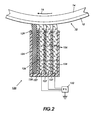
- the ionically conductive liquid charging apparatus of this alternative embodiment is comprised of a housing 124 for supporting a plurality of wetted liquid donor blades 126 in contact with the surface 12 of photoreceptor 10.
- Housing 124 is fabricated of an insulative material such as a polymer.
- the housing 124 is fabricated from a material which is not susceptible to corrosion upon exposure to the particular ionically conductive liquid utilized by the ionically conductive liquid charging apparatus.
- the housing 124 may also serve as a reservoir for storing an amount of the ionically conductive liquid used to wet the liquid donor blades 126 supported therein.
- ionically conductive liquid materials which may serve satisfactorily in the context of the present embodiment include any liquid based material capable of conducting ions, including simple tap water and even distilled or deionized water (where the conductivity thereof is believed to be caused by the known dissolution of carbon dioxide in water).
- Components which can be added to the water to render it more ionically conductive include atmospheric carbon dioxide (CO 2 ), lithium carbonate sodium carbonate, potassium carbonate, sodium bicarbonate and the like. The concentration ranges can vary from trace levels to saturation.
- Another example of an ionically conductive medium is a gel that is composed of 96 wt % water and 4 wt % acrylic acid neutralized with NaOH.
- hydrogels include polyhydroxyethylmethacrylates, polyacrylates, polyvinylpyrrolodonone and the like.
- Other gel materials include gelatin, gums and mucilages both natural and synthetic. Numerous other fluid compounds and materials which may be desirable for use with the apparatus of the present embodiment are described in US-A-5,510,879.
- Donor blades 126 are relatively flexible blade members which may be fabricated from a porous or microporous elastomeric polymer like polyurethane of polyvinylalcohol-co-polyvinylformal (polyvinyl crosslinked with formaldehyde) which provides for bringing the pure liquid or ionically conductive liquid in contact with the photoreceptor 12.
- the blade members should be wettable, preferably hydrophilic by the particular ionically conductive liquid being utilized, especially when the liquid is water.
- polyurethane foam, compressed polyurethane foam, or polyvynilalcohol-co-polyvynilformal foam can be used to provide a compliant blade member.
- the donor blades 126 can be fabricated from a hydrophobic polymer, for example VITON®, a copolymer of vinylidene fluoride/hexafluoropropylene and tetrafluoroethylene.
- the surface of the blade can be chemically treated so as to make it hydrophilic. For example, it may be treated by exposure to ozone gas, or other oxidizing agents such as chromic acid.
- VITON® hydrophilic is to roughen it with fine sand paper.
- Other hydrophobic polymers for the donor blade include polyethylene, polypropylene, polyethylpentane, polybutadiene and silicone elastomers.
- the surface of the blade members 126 may alternatively be rendered hydrophilic by filling the elastomer with finely divided conductive particles, such as aluminum, zinc or oxidized carbon black, aluminum oxide, tin oxide, titanium dioxide, zinc oxide and the like, to the extent of 0.1 to 10 percent.
- conductive particles such as aluminum, zinc or oxidized carbon black, aluminum oxide, tin oxide, titanium dioxide, zinc oxide and the like.
- Both the conductive and semiconductive particles can be embedded in the surface layer of the elastomer by heating the elastomer above its glass transition temperature or by depositing a layer of adhesive onto the elastomer and spraying the particles onto the surface.
- the thickness of this layer can be from 0.1 micron to 100 microns, and preferably is from about 10 to about 50 microns with a harness of from about 10 A to about 60 A on the Shore durometer Scale.
- the preferred embodiment of the present invention include support members 127, fixed within the housing 124 and situated I abutment with each donor blades 126, downstream from each donor blade 126 relative to the direction of travel 16 of the photoreceptor surface 12.
- the support members 127 is fabricated from a relatively rigid material with respect to the donor blades 126, providing structural integrity for urging the donor blade 26 against the photoreceptor surface 12. It has been found that a thin strip of MYLAR® provides an effective support member 27,
- the alternative embodiment shown in FIG. 2 also includes a wiper blade 28.
- the wiper blade 128 is provided for removing any small amount of fluid from the surface of the photoreceptor 12, as may have been transferred thereto at the interface between the wetted donor blade 126 and the photoreceptor surface 12.
- a polyurethane type blade situated downstream from the donor blades 126 and support blades 127 relative to the direction of travel 16 of the photoreceptor surface 12 is provided for eliminating transfer of water or other liquid to the photoreceptor surface.
- the use of a wiper blade also advantageously permits a higher concentration of liquid to be applied by the donor blades 126.
- the effectiveness of the wiper blade 128 can be enhanced by optimizing such factors as the liquid concentration at the donor blades 126/photoreceptor surface 12 interface, the wipe angle of the wiper blade 128 as well as the stiffness of the wiper blade 128.
- the wiper blade 128 also provides increased operational lifetime to the charging system of the present invention by returning the ionically conductive liquid to the donor blades 126 or to a reservoir coupled to the donor blade 126 for use in successive charging operations.
- a liquid management system (not shown) may be provided for adding liquid to the housing 124 of the charging apparatus 20 for continually moistening the donor blades 126.
- the fluid in housing 124 may be prevented from leaking out of the housing 124 by a lubricated rubber gasket or shoe 129.
- the rubber is selected to conform to asperities in the photoreceptor surface 12 and to any curvature in the photoreceptor, such as a drum 10.
- the device of the present invention enables ionic conduction charging of a photoconductive imaging member, or any member placed in contact therewith, by placing an ionically conductive liquid component in contact with the surface of the photoconductive imaging member and applying a voltage to the ionically conductive liquid component such that ions are transferred across the liquid photoreceptive member interface to the photoreceptor surface.
- the photoreceptor thus becomes charged by the flow of ions through the liquid component.
- the ionically conductive liquid is biased by a voltage approximately equal to the surface potential desired on the photoreceptor, causing ions to be deposited at the point of contact between the ionic liquid and the photoreceptor until the electric field thereacross is completely diminished.
- the photoreceptor is charged by wetting a conductive foam component contained in a housing, with wedging rods attaching to foam components to separate voltages of a power supply 122.
- the photoreceptor is situated so as to contact the foam members.
- This voltage causes the HCO 3 - and H3O+ ions present in distilled or deionized water in equilibrium with air in the water to separate.
- positive ions migrate toward the imaging member, and when a negative voltage is applied from the power source negative ions migrate toward the imaging member.
- Rotation or translation of the imaging member causes charge to transfer form the foam to the imaging member, which charge is substantially equivalent or equivalent to the voltage applied from the power source.
- each donor blade 126 is isolated from one another and independently coupled to an independent output port of power supply 122 such that each donor member is provided with an independent biasing voltage. Further, in accordance with the present invention, each donor blade 126 is independently biased to an incrementally increasing bias voltage which permits high level charge to be induced on the surface of a member in contact therewith while not exceeding the Paschen threshold voltage necessary to create air breakdown.
Landscapes
- Physics & Mathematics (AREA)
- Engineering & Computer Science (AREA)
- Plasma & Fusion (AREA)
- General Physics & Mathematics (AREA)
- Electrostatic Charge, Transfer And Separation In Electrography (AREA)
Applications Claiming Priority (2)
| Application Number | Priority Date | Filing Date | Title |
|---|---|---|---|
| US939642 | 1997-09-29 | ||
| US08/939,642 US5832346A (en) | 1997-09-29 | 1997-09-29 | Multi-point contact charging device |
Publications (1)
| Publication Number | Publication Date |
|---|---|
| EP0905576A1 true EP0905576A1 (en) | 1999-03-31 |
Family
ID=25473511
Family Applications (1)
| Application Number | Title | Priority Date | Filing Date |
|---|---|---|---|
| EP98307438A Withdrawn EP0905576A1 (en) | 1997-09-29 | 1998-09-14 | Charging device |
Country Status (3)
| Country | Link |
|---|---|
| US (1) | US5832346A (enExample) |
| EP (1) | EP0905576A1 (enExample) |
| JP (1) | JPH11160963A (enExample) |
Families Citing this family (8)
| Publication number | Priority date | Publication date | Assignee | Title |
|---|---|---|---|---|
| DE10019678A1 (de) * | 2000-04-19 | 2001-10-25 | Sgl Carbon Ag | Flächiges Halbzeug und Verfahren zu dessen Herstellung |
| US6807389B2 (en) * | 2002-12-13 | 2004-10-19 | Xerox Corporation | Bias charge roller with optimally induced AC corona |
| JP2008257183A (ja) * | 2007-03-13 | 2008-10-23 | Ricoh Co Ltd | 帯電ブラシ、帯電装置、プロセスユニット及び画像形成装置 |
| US8362673B2 (en) * | 2009-04-06 | 2013-01-29 | ISC8 Inc. | Micro-image acquisition and transmission system |
| JP2011197422A (ja) * | 2010-03-19 | 2011-10-06 | Konica Minolta Business Technologies Inc | 画像形成装置及び帯電方法 |
| US20130287961A1 (en) * | 2010-06-07 | 2013-10-31 | Tufts University | Reversible contact electrification |
| JP5907414B2 (ja) * | 2012-02-27 | 2016-04-26 | 富士ゼロックス株式会社 | 帯電装置および画像形成装置 |
| US9141037B2 (en) * | 2013-08-15 | 2015-09-22 | Xerox Corporation | Transfer assist members |
Citations (7)
| Publication number | Priority date | Publication date | Assignee | Title |
|---|---|---|---|---|
| JPS56104349A (en) * | 1980-01-24 | 1981-08-20 | Toshiba Corp | Charging device of electrophotographic copier |
| JPS58139156A (ja) * | 1982-02-13 | 1983-08-18 | Canon Inc | 帯電方法 |
| JPS58147757A (ja) * | 1982-02-25 | 1983-09-02 | Kinoshita Kenkyusho:Kk | 電子写真方法 |
| EP0508355A2 (en) * | 1991-04-10 | 1992-10-14 | Kabushiki Kaisha TEC | Device for charging a photosensitive body |
| JPH0784436A (ja) * | 1993-09-17 | 1995-03-31 | Ricoh Co Ltd | 画像形成装置及び帯電装置 |
| US5602626A (en) * | 1995-07-03 | 1997-02-11 | Xerox Corporation | Ionically conductive liquid charging apparatus |
| US5781833A (en) * | 1995-12-01 | 1998-07-14 | Xerox Corporation | Sealed liquid charging apparatus |
Family Cites Families (5)
| Publication number | Priority date | Publication date | Assignee | Title |
|---|---|---|---|---|
| US3684364A (en) * | 1971-06-24 | 1972-08-15 | Xerox Corp | Lift off electrode |
| DE3048141C2 (de) * | 1979-12-25 | 1982-12-23 | Tokyo Shibaura Denki K.K., Kawasaki, Kanagawa | Einrichtung zum gleichförmigen Aufladen eines fotoleitfähigen Aufzeichnungsmaterials |
| US4336565A (en) * | 1980-08-04 | 1982-06-22 | Xerox Corporation | Charge process with a carbon fiber brush electrode |
| US4761709A (en) * | 1984-10-29 | 1988-08-02 | Xerox Corporation | Contact brush charging |
| JP3214120B2 (ja) * | 1992-12-24 | 2001-10-02 | キヤノン株式会社 | 帯電装置及び画像形成装置 |
-
1997
- 1997-09-29 US US08/939,642 patent/US5832346A/en not_active Expired - Fee Related
-
1998
- 1998-09-14 EP EP98307438A patent/EP0905576A1/en not_active Withdrawn
- 1998-09-18 JP JP10264245A patent/JPH11160963A/ja not_active Withdrawn
Patent Citations (7)
| Publication number | Priority date | Publication date | Assignee | Title |
|---|---|---|---|---|
| JPS56104349A (en) * | 1980-01-24 | 1981-08-20 | Toshiba Corp | Charging device of electrophotographic copier |
| JPS58139156A (ja) * | 1982-02-13 | 1983-08-18 | Canon Inc | 帯電方法 |
| JPS58147757A (ja) * | 1982-02-25 | 1983-09-02 | Kinoshita Kenkyusho:Kk | 電子写真方法 |
| EP0508355A2 (en) * | 1991-04-10 | 1992-10-14 | Kabushiki Kaisha TEC | Device for charging a photosensitive body |
| JPH0784436A (ja) * | 1993-09-17 | 1995-03-31 | Ricoh Co Ltd | 画像形成装置及び帯電装置 |
| US5602626A (en) * | 1995-07-03 | 1997-02-11 | Xerox Corporation | Ionically conductive liquid charging apparatus |
| US5781833A (en) * | 1995-12-01 | 1998-07-14 | Xerox Corporation | Sealed liquid charging apparatus |
Non-Patent Citations (4)
| Title |
|---|
| PATENT ABSTRACTS OF JAPAN vol. 005, no. 175 (P - 088) 11 November 1981 (1981-11-11) * |
| PATENT ABSTRACTS OF JAPAN vol. 007, no. 256 (P - 236) 15 November 1983 (1983-11-15) * |
| PATENT ABSTRACTS OF JAPAN vol. 007, no. 266 (P - 239) 26 November 1983 (1983-11-26) * |
| PATENT ABSTRACTS OF JAPAN vol. 095, no. 006 31 July 1995 (1995-07-31) * |
Also Published As
| Publication number | Publication date |
|---|---|
| JPH11160963A (ja) | 1999-06-18 |
| US5832346A (en) | 1998-11-03 |
Similar Documents
| Publication | Publication Date | Title |
|---|---|---|
| US4974027A (en) | Imaging system with compactor and squeegee | |
| US4984025A (en) | Imaging system with intermediate transfer member | |
| US5481341A (en) | Roller for controlling application of carrier liquid | |
| JP3863222B2 (ja) | 帯電装置及び静電写真印刷装置 | |
| EP0905576A1 (en) | Charging device | |
| US5561505A (en) | Mechanically sealable liquid charging apparatus | |
| US5781833A (en) | Sealed liquid charging apparatus | |
| US7184695B2 (en) | Image forming apparatus and elastic roller | |
| CA1084770A (en) | Image transfer unit for electrophotographic copying machines | |
| JPH10228158A (ja) | 接触帯電装置 | |
| JPH0862938A (ja) | 帯電・クリーニング兼用装置 | |
| JP3568089B2 (ja) | 転写ベルト装置 | |
| JP2798969B2 (ja) | ローラ転写装置 | |
| JPS63208880A (ja) | 帯電装置 | |
| JPH0862937A (ja) | 帯電・クリーニング兼用装置 | |
| JPH11218999A (ja) | 帯電装置 | |
| JP3311440B2 (ja) | 転写ベルト装置 | |
| JP3680657B2 (ja) | 帯電装置及びこれを用いた画像形成装置 | |
| JPS5926773A (ja) | クリ−ニング装置 | |
| JPH11218996A (ja) | 帯電装置 | |
| JPH11212333A (ja) | 帯電装置 | |
| JP2000284585A (ja) | 電子写真記録用ローラ | |
| JP2002091139A (ja) | 画像形成装置 | |
| JP2000047453A (ja) | 画像形成装置 | |
| JPH0876557A (ja) | 電荷供給装置 |
Legal Events
| Date | Code | Title | Description |
|---|---|---|---|
| PUAI | Public reference made under article 153(3) epc to a published international application that has entered the european phase |
Free format text: ORIGINAL CODE: 0009012 |
|
| AK | Designated contracting states |
Kind code of ref document: A1 Designated state(s): DE FR GB |
|
| AX | Request for extension of the european patent |
Free format text: AL;LT;LV;MK;RO;SI |
|
| 17P | Request for examination filed |
Effective date: 19990930 |
|
| AKX | Designation fees paid |
Free format text: DE FR GB |
|
| 17Q | First examination report despatched |
Effective date: 20020521 |
|
| STAA | Information on the status of an ep patent application or granted ep patent |
Free format text: STATUS: THE APPLICATION IS DEEMED TO BE WITHDRAWN |
|
| 18D | Application deemed to be withdrawn |
Effective date: 20041216 |