EP0905353B1 - Ensemble des jets d'air pour un procédé de chauffage ou de refroidissement par convection - Google Patents
Ensemble des jets d'air pour un procédé de chauffage ou de refroidissement par convection Download PDFInfo
- Publication number
- EP0905353B1 EP0905353B1 EP97810718A EP97810718A EP0905353B1 EP 0905353 B1 EP0905353 B1 EP 0905353B1 EP 97810718 A EP97810718 A EP 97810718A EP 97810718 A EP97810718 A EP 97810718A EP 0905353 B1 EP0905353 B1 EP 0905353B1
- Authority
- EP
- European Patent Office
- Prior art keywords
- impact
- impingement
- wall
- cooling
- tubs
- Prior art date
- Legal status (The legal status is an assumption and is not a legal conclusion. Google has not performed a legal analysis and makes no representation as to the accuracy of the status listed.)
- Expired - Lifetime
Links
Images


Classifications
-
- F—MECHANICAL ENGINEERING; LIGHTING; HEATING; WEAPONS; BLASTING
- F01—MACHINES OR ENGINES IN GENERAL; ENGINE PLANTS IN GENERAL; STEAM ENGINES
- F01D—NON-POSITIVE DISPLACEMENT MACHINES OR ENGINES, e.g. STEAM TURBINES
- F01D5/00—Blades; Blade-carrying members; Heating, heat-insulating, cooling or antivibration means on the blades or the members
- F01D5/12—Blades
- F01D5/14—Form or construction
- F01D5/18—Hollow blades, i.e. blades with cooling or heating channels or cavities; Heating, heat-insulating or cooling means on blades
- F01D5/187—Convection cooling
- F01D5/188—Convection cooling with an insert in the blade cavity to guide the cooling fluid, e.g. forming a separation wall
- F01D5/189—Convection cooling with an insert in the blade cavity to guide the cooling fluid, e.g. forming a separation wall the insert having a tubular cross-section, e.g. airfoil shape
-
- F—MECHANICAL ENGINEERING; LIGHTING; HEATING; WEAPONS; BLASTING
- F05—INDEXING SCHEMES RELATING TO ENGINES OR PUMPS IN VARIOUS SUBCLASSES OF CLASSES F01-F04
- F05D—INDEXING SCHEME FOR ASPECTS RELATING TO NON-POSITIVE-DISPLACEMENT MACHINES OR ENGINES, GAS-TURBINES OR JET-PROPULSION PLANTS
- F05D2260/00—Function
- F05D2260/20—Heat transfer, e.g. cooling
- F05D2260/201—Heat transfer, e.g. cooling by impingement of a fluid
-
- F—MECHANICAL ENGINEERING; LIGHTING; HEATING; WEAPONS; BLASTING
- F05—INDEXING SCHEMES RELATING TO ENGINES OR PUMPS IN VARIOUS SUBCLASSES OF CLASSES F01-F04
- F05D—INDEXING SCHEME FOR ASPECTS RELATING TO NON-POSITIVE-DISPLACEMENT MACHINES OR ENGINES, GAS-TURBINES OR JET-PROPULSION PLANTS
- F05D2260/00—Function
- F05D2260/20—Heat transfer, e.g. cooling
- F05D2260/221—Improvement of heat transfer
- F05D2260/2212—Improvement of heat transfer by creating turbulence
-
- Y—GENERAL TAGGING OF NEW TECHNOLOGICAL DEVELOPMENTS; GENERAL TAGGING OF CROSS-SECTIONAL TECHNOLOGIES SPANNING OVER SEVERAL SECTIONS OF THE IPC; TECHNICAL SUBJECTS COVERED BY FORMER USPC CROSS-REFERENCE ART COLLECTIONS [XRACs] AND DIGESTS
- Y02—TECHNOLOGIES OR APPLICATIONS FOR MITIGATION OR ADAPTATION AGAINST CLIMATE CHANGE
- Y02T—CLIMATE CHANGE MITIGATION TECHNOLOGIES RELATED TO TRANSPORTATION
- Y02T50/00—Aeronautics or air transport
- Y02T50/60—Efficient propulsion technologies, e.g. for aircraft
Definitions
- the invention relates to an impact arrangement for a convective cooling or heating method according to the preamble of claim 1.
- Impact cooling of the type mentioned at the outset is known from GB 849255.
- the method shown there is characterized by a plurality of impingement tubes which are directed with their mouths against the wall part to be cooled, the support being arranged at a distance from the wall part.
- the wall to be cooled is equipped with a plurality of cylindrical cooling pockets, into each of which an impact jet is directed.
- Such a wall configuration with sharp edges and small radii results in an uneven cooling effect and unfavorable flow conditions. Outside the cylindrical pockets, the heat transfer drops significantly. The result is an inhomogeneous temperature distribution on the hot wall side.
- the wall impacted by the impact beams is designed as a relief with protruding humps, the beams hitting the protruding humps directly (FIG. 3). This is to compensate for the inhomogeneous heat transfer in the impact jets and to achieve a homogeneous temperature distribution on the hot side of the wall.
- the humps are essentially designed as cylinders with rounded edges due to the manufacturing process.
- the relief is in the form of ribs. Both geometries have no advantageous thermal boundary conditions with regard to heat transfer.
- the heat that can be given off over the surface of an element protruding from the wall to be cooled must first be conducted to the surface through its base area and the material. This results in a temperature stratification in the material of the element. Depending on the material and geometry, this can lead to the temperature difference between the fluid and the element becoming so small at the points furthest from the base of the element that practically no heat transfer takes place.
- EP 0 889 is in the earlier priority application 201 has been encouraged to configure such a baffle arrangement in such a way that the impact beams are always directed between the hump-shaped roughness elements and the forming curve of this protruding hump is the contour of a Paraboloid of revolution.
- Such a configuration ensures one high thermal effectiveness of the impact beams hitting the wall in several ways; on the one hand, there is a high one in the area where the rays strike Heat transfer before, on the other hand ensures an unhindered outflow of the Impact medium over the flow-optimized hump area for very high Heat transfer rates.
- the roughness elements are either placed on the wall to be cooled or executed as a uniform casting. In the latter case, the cheap one Geometry of this structure bought by an increased manufacturing effort.
- the invention has for its object to provide a baffle arrangement which the roughness elements related to the manufacturing process and the thermal effectiveness are optimized. Starting from the above Proposed solutions of the prior art should do this by creating a new geometry of the relief structure can be achieved.
- the webs between the tubs can be spaced beam generating plate or depending on the design of this plate can even be used directly as a spacer when the plate is on the webs rests.
- impingement flow is referred to as impingement cooling, for example for cooling hot turbomachine components with flow such as gas turbine blades or combustion chamber walls are used can.
- the wall part to be cooled for example by means of cooling air 5, is 3 designated. It is a flat wall, which is on the outside is flowed around by a hot medium indicated by the arrows 6.
- the carrier 1 on the cooling air side is also designed accordingly. He is in shown case with constant distance 20 by means of suitable, not shown Means attached to the wall 3.
- the carrier has a plurality of Baffle openings 2 and can be designed as a simple perforated plate.
- the wall 3 On the inside is the wall 3 to be cooled with a number arranged side by side Provide tubs 4. These tubs have the shape in the example of domes on. The distance between the tubs is chosen so that a narrow web 7 between the adjacent tub walls results. Compared to a level training, the dome-shaped configuration of the cooling wall a considerable increase in heat transfer Area and thus the heat flow.
- the side of the wall part 3 facing away from the impact beam is flat in the example educated. It goes without saying that this side facing away from the impact beam is precise can be provided with a curvature as well, the radius of curvature then, however, should be much larger than that of the calotte.
- the wall part to be cooled is preferably cast in one piece together with the tubs. Regardless of the manufacturing process, a structure of high strength results.
- the structured surface impacted by the impact beams carries - related to the basic thickness a of wall 3 - decisive for the rigidity of the overall system at. On the one hand, this can lead to an advantageous reduction in the base wall thickness a lead if the smallest possible mass of the system is required is. Or on the other hand, while maintaining the basic strength a and constant mechanical stress the fluid temperature on the hot side be increased accordingly. Finally, while maintaining the basic strength a and the temperature of the hot fluid with the new measure Extend the life of the system.
- An impact jet is provided for each trough, this exiting from the impact opening 2 emerging impact beam usually at least approximately perpendicular to the Tub floor hits.
- the impact jet is directed onto the remaining impact surface, i.e. the walls of the tub, redirected.
- the flow around the calotte heated coolant then flows into the space between the support and the wall part from, the resulting cross-flow also for cooling the webs 7 contributes.
- FIG. 2 There there are only symmetrically constructed elements Half of the tub shown.
- a circle around its diameter is used to produce it 2 a shows an elliptical shape. As with the spherical cap this shape is also rotated around the corresponding section Axis U generated.
- Fig. 2c finally shows a trapezoidal trough with a flat bottom, the Walls can be straight or curved (as shown).
- a composite is created honeycomb structure, the individual elements of which are each assigned a free jet is. This is positioned so that its core under the given boundary conditions - i.a. the cross flow of the outflowing cooling medium from neighboring elements - a stagnation point in the lower floor area of the Tubs.
- the axis position of the free jet can change from the axis of rotation of the rotating body.
- the geometry to be selected should influence the heat flow in such a way that the surface temperature only increases with increasing distance from the base decreases insignificantly and thus an almost constant heat flow through the entire surface can flow.
- Relative to the cross flow in the area of the base can basically distinguish two arrangements.
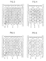
- baffle openings 2 and the troughs 4 can either be connected in series 3 or they can be offset from one another, for example by half a division according to FIG. 4. This results in arrangements, which are either square or hexagonal, like the dashed ones Lines in Fig. 3 respectively. 4 show.
- the tubs 4 are preferably at the crossing points of these dashed lines arranged. As shown in Fig. 3, are in row arrangement directly adjacent tubs without gaps, i.e. arranged without bars. Nevertheless, in this version in the middle of 4 tubs are relative large bridges 7 formed. Spacers to the carrier can be placed on these webs be provided, these spacers also integrally potted with the wall 3 could be.
- the geometry of the arrangement according to FIG. 5 corresponds to that of FIG. 3
- the size and the mutual distance between the baffle openings 2 are chosen to be the same.
- the diameter D of the tubs was increased, resulting in a Intersection of adjacent tubs and leads to smaller webs 7.
- This Solution can have manufacturing advantages and, depending on the choice of Lead to flatter troughs.
- the geometry of the arrangement according to FIG. 6 corresponds to that of FIG. 4.
- the size and the mutual distance between the baffle openings 2 are again the same selected.
- the diameter D of the tubs was increased, which too intersection of adjacent tubs and extremely small webs. You can see here that from a certain tub diameter at all no more bars are formed.
- FIG. 7 shows a gas turbine blade 16 as an example of a component to be cooled shown.
- the carriers with the baffle openings 2 are more or less tubular Inserts 17A, 17B and 17C designed and in the hollow interior of the blade arranged.
- These inserts as well as the bucket wall provided with the tubs 4 can be designed as a cast part. They can also be used as pressure-bearing Formations can be designed for internal pressures that are up to double the in the actual impact zone prevailing pressure.
- the coolant flows into the inserts usually from the blade root towards the tip of the blade.
- the baffle openings 2 and the tubs 4 are in about the bucket height and the bucket circumference required distance from each other. inserts 17A-C can be used from Coolants are flowed through individually or in series.
- the gaseous or vaporous cooling medium can be used in several applications closed circle, i.e. it becomes after cooling pulled back over the blade root. That from the cooled wall parts outflowing cooling medium can, however, out of the blade in the Exit the flow channel. This is preferably done at that point in the Bucket at which the lowest external pressure prevails. Usually you will the coolant can thus escape at the rear edge 18 of the blade.
- Fig. 8 shows an embodiment in which the carrier is also sheet-like is and with a variety, here equidistant and arranged in rows
- Baffle tubes 21 is provided.
- the inlet 22 corresponds to a baffle opening and is flush with the support surface.
- the baffle tubes have a conical inner channel with constant narrowing in the direction of flow. The narrowest cross section the baffle tubes are thus at the mouth 23. With their mouth 23 are the baffle tubes directed vertically against the wall part to be cooled. The mouth is at an impact distance of 25 to the wall. In the example, the ratio is this Impact distance to the narrowest diameter of the baffle tubes is approximately 1. It can be seen that the cooling air deflected after the impact into the free spaces 21 can flow between the baffle tubes without adjacent baffle jets disturb.
- the light-free dimension of the space is vertical Alignment of the baffle tubes given by their length.
- This solution offers the cooling air jets that are generated via a perforated plate Advantage of free design of the ratio of the beam distance to Beam diameter which is quite a range from 0.1 to 4 can extend.
- the tubs have always been viewed as rotationally symmetrical bodies that by rotating the corresponding section through 360 °.
- the troughs it is of course also possible for the troughs to be trough-shaped to design, although the surface enlargement somewhat smaller fails as with rotationally symmetrical tubs.
- To create a gutter the corresponding section is not rotated about an axis U, but along one preferably straight axis U shifted. This gives rise to the cooling surface longitudinal channels with circular, elliptical or trapezoidal shape. At this Configuration occurs the stabilizing effect of the surface-enlarging structure in a defined direction. The impact beams are intended for this solution also hit the bottom of the gutter.
- the carrier 1 is a flat one Perforated plate. 9, however, a perforated plate with dome-like Sinks 26 are used.
- the depressions each contain the baffle openings 2, whereby it can be seen that this solution provides a simple means is to influence the impact distance 25.
- the tubs are trough-shaped are trained, it also makes sense to close the depressions 26 as channels shape. These do not necessarily have to run in the same direction like the tubs. You can choose any angle between 0 ° and 90 ° run to the tub direction or to the direction of the cooling stream 6.
- the Intermediate spaces 27 present between the depressions can thereby be used targeted removal of the cooling medium can be used.
- the different course of the direction the possibility of the trough-shaped depression 26 to be supported directly on the webs 7 of the tub (not shown).
- the invention is not limited to that shown and described Examples limited. It is understood that depending on the requirements, the number and division of the baffle openings 2 or tubes 21, and the length and shape of the latter, can be optimized on a case-by-case basis. Also in the choice of the coolant, its Pressure and its further use after cooling Invention no barriers.
Claims (1)
- Ensemble de jets d'air, dans lequel une pluralité d'ouvertures à jets (2) est disposée en forme de surface dans un support plan ou courbe (1), et le support (1) est disposé à distance d'une partie de paroi (3), dont la face d'impact à refroidir ou à chauffer est configurée en relief avec un certain nombre de cuvettes (4) disposées les unes à côté des autres, dans lequel il est prévu par cuvette (4) au moins un jet, qui frappe le fond de la cuvette au moins à peu près perpendiculairement, et la face de la partie de paroi (3) située à l'opposé du jet est de forme au moins approximativement plane, caractérisé en ce que les cuvettes (4) possèdent une section transversale en forme de portion de cercle, d'ellipse ou de cycloïde raccourci et sont configurées soit avec la symétrie de révolution soit avec une forme allongée par déplacement le long d'un axe rectiligne.
Priority Applications (4)
| Application Number | Priority Date | Filing Date | Title |
|---|---|---|---|
| EP97810718A EP0905353B1 (fr) | 1997-09-30 | 1997-09-30 | Ensemble des jets d'air pour un procédé de chauffage ou de refroidissement par convection |
| DE59709158T DE59709158D1 (de) | 1997-09-30 | 1997-09-30 | Prallanordnung für ein konvektives Kühl- oder Heizverfahren |
| JP10276133A JPH11159301A (ja) | 1997-09-30 | 1998-09-29 | 壁部分用の衝流システム |
| US10/002,633 US20020062945A1 (en) | 1997-09-30 | 2001-12-05 | Wall part acted upon by an impingement flow |
Applications Claiming Priority (1)
| Application Number | Priority Date | Filing Date | Title |
|---|---|---|---|
| EP97810718A EP0905353B1 (fr) | 1997-09-30 | 1997-09-30 | Ensemble des jets d'air pour un procédé de chauffage ou de refroidissement par convection |
Publications (2)
| Publication Number | Publication Date |
|---|---|
| EP0905353A1 EP0905353A1 (fr) | 1999-03-31 |
| EP0905353B1 true EP0905353B1 (fr) | 2003-01-15 |
Family
ID=8230407
Family Applications (1)
| Application Number | Title | Priority Date | Filing Date |
|---|---|---|---|
| EP97810718A Expired - Lifetime EP0905353B1 (fr) | 1997-09-30 | 1997-09-30 | Ensemble des jets d'air pour un procédé de chauffage ou de refroidissement par convection |
Country Status (4)
| Country | Link |
|---|---|
| US (1) | US20020062945A1 (fr) |
| EP (1) | EP0905353B1 (fr) |
| JP (1) | JPH11159301A (fr) |
| DE (1) | DE59709158D1 (fr) |
Cited By (3)
| Publication number | Priority date | Publication date | Assignee | Title |
|---|---|---|---|---|
| US11859824B2 (en) | 2022-05-13 | 2024-01-02 | General Electric Company | Combustor with a dilution hole structure |
| US11859823B2 (en) | 2022-05-13 | 2024-01-02 | General Electric Company | Combustor chamber mesh structure |
| US11867398B2 (en) | 2022-05-13 | 2024-01-09 | General Electric Company | Hollow plank design and construction for combustor liner |
Families Citing this family (65)
| Publication number | Priority date | Publication date | Assignee | Title |
|---|---|---|---|---|
| US6589600B1 (en) * | 1999-06-30 | 2003-07-08 | General Electric Company | Turbine engine component having enhanced heat transfer characteristics and method for forming same |
| EP1409926B1 (fr) * | 1999-08-03 | 2004-11-03 | Siemens Aktiengesellschaft | Dispositif de refroidissement par choc |
| US6164914A (en) * | 1999-08-23 | 2000-12-26 | General Electric Company | Cool tip blade |
| US6302185B1 (en) * | 2000-01-10 | 2001-10-16 | General Electric Company | Casting having an enhanced heat transfer surface, and mold and pattern for forming same |
| EP1136651A1 (fr) * | 2000-03-22 | 2001-09-26 | Siemens Aktiengesellschaft | Système de refroidissement pour une aube de turbine à gaz |
| WO2001071164A1 (fr) * | 2000-03-22 | 2001-09-27 | Siemens Aktiengesellschaft | Structure de rigidification et de refroidissement d'une aube de turbine |
| AU2002237668A1 (en) * | 2000-11-21 | 2002-06-03 | Michael R. Adams | Portable low-power gas discharge laser |
| GB2420156B (en) | 2004-11-16 | 2007-01-24 | Rolls Royce Plc | A heat transfer arrangement |
| FR2893080B1 (fr) * | 2005-11-07 | 2012-12-28 | Snecma | Agencement de refroidissement d'une aube d'une turbine, aube de turbine le comportant, turbine et moteur d'aeronef en etant equipes |
| GB0601413D0 (en) * | 2006-01-25 | 2006-03-08 | Rolls Royce Plc | Wall elements for gas turbine engine combustors |
| US7362574B2 (en) * | 2006-08-07 | 2008-04-22 | International Business Machines Corporation | Jet orifice plate with projecting jet orifice structures for direct impingement cooling apparatus |
| JP5029960B2 (ja) * | 2008-01-15 | 2012-09-19 | 株式会社Ihi | 高温部品の内面冷却構造 |
| EP2143883A1 (fr) * | 2008-07-10 | 2010-01-13 | Siemens Aktiengesellschaft | Aube de turbine et moyau de coulée de fabrication |
| JP5222057B2 (ja) * | 2008-08-08 | 2013-06-26 | 三菱重工業株式会社 | ガスタービン高温部の冷却装置 |
| US7983040B2 (en) * | 2008-10-23 | 2011-07-19 | International Business Machines Corporation | Apparatus and method for facilitating pumped immersion-cooling of an electronic subsystem |
| US7961475B2 (en) | 2008-10-23 | 2011-06-14 | International Business Machines Corporation | Apparatus and method for facilitating immersion-cooling of an electronic subsystem |
| US7885070B2 (en) * | 2008-10-23 | 2011-02-08 | International Business Machines Corporation | Apparatus and method for immersion-cooling of an electronic system utilizing coolant jet impingement and coolant wash flow |
| US7944694B2 (en) | 2008-10-23 | 2011-05-17 | International Business Machines Corporation | Liquid cooling apparatus and method for cooling blades of an electronic system chassis |
| US7916483B2 (en) * | 2008-10-23 | 2011-03-29 | International Business Machines Corporation | Open flow cold plate for liquid cooled electronic packages |
| CH700319A1 (de) * | 2009-01-30 | 2010-07-30 | Alstom Technology Ltd | Gekühltes bauelement für eine gasturbine. |
| US8348613B2 (en) | 2009-03-30 | 2013-01-08 | United Technologies Corporation | Airflow influencing airfoil feature array |
| US8059405B2 (en) * | 2009-06-25 | 2011-11-15 | International Business Machines Corporation | Condenser block structures with cavities facilitating vapor condensation cooling of coolant |
| US7885074B2 (en) * | 2009-06-25 | 2011-02-08 | International Business Machines Corporation | Direct jet impingement-assisted thermosyphon cooling apparatus and method |
| US8018720B2 (en) * | 2009-06-25 | 2011-09-13 | International Business Machines Corporation | Condenser structures with fin cavities facilitating vapor condensation cooling of coolant |
| US8490679B2 (en) * | 2009-06-25 | 2013-07-23 | International Business Machines Corporation | Condenser fin structures facilitating vapor condensation cooling of coolant |
| US8014150B2 (en) * | 2009-06-25 | 2011-09-06 | International Business Machines Corporation | Cooled electronic module with pump-enhanced, dielectric fluid immersion-cooling |
| US8305755B2 (en) * | 2010-03-04 | 2012-11-06 | Toyota Motor Engineering & Manufacturing North America, Inc. | Power modules, cooling devices and methods thereof |
| US8184436B2 (en) | 2010-06-29 | 2012-05-22 | International Business Machines Corporation | Liquid-cooled electronics rack with immersion-cooled electronic subsystems |
| US8369091B2 (en) | 2010-06-29 | 2013-02-05 | International Business Machines Corporation | Interleaved, immersion-cooling apparatus and method for an electronic subsystem of an electronics rack |
| US8179677B2 (en) | 2010-06-29 | 2012-05-15 | International Business Machines Corporation | Immersion-cooling apparatus and method for an electronic subsystem of an electronics rack |
| US8351206B2 (en) | 2010-06-29 | 2013-01-08 | International Business Machines Corporation | Liquid-cooled electronics rack with immersion-cooled electronic subsystems and vertically-mounted, vapor-condensing unit |
| US8345423B2 (en) | 2010-06-29 | 2013-01-01 | International Business Machines Corporation | Interleaved, immersion-cooling apparatuses and methods for cooling electronic subsystems |
| GB2492374A (en) * | 2011-06-30 | 2013-01-02 | Rolls Royce Plc | Gas turbine engine impingement cooling |
| JP5791406B2 (ja) * | 2011-07-12 | 2015-10-07 | 三菱重工業株式会社 | 回転機械の翼体 |
| JP5791405B2 (ja) * | 2011-07-12 | 2015-10-07 | 三菱重工業株式会社 | 回転機械の翼体 |
| US9039350B2 (en) * | 2012-01-09 | 2015-05-26 | General Electric Company | Impingement cooling system for use with contoured surfaces |
| ITTO20120519A1 (it) * | 2012-06-14 | 2013-12-15 | Avio Spa | Turbina a gas per motori aeronautici |
| US8951004B2 (en) * | 2012-10-23 | 2015-02-10 | Siemens Aktiengesellschaft | Cooling arrangement for a gas turbine component |
| US10270220B1 (en) * | 2013-03-13 | 2019-04-23 | Science Research Laboratory, Inc. | Methods and systems for heat flux heat removal |
| US10508808B2 (en) * | 2013-06-14 | 2019-12-17 | United Technologies Corporation | Gas turbine engine wave geometry combustor liner panel |
| JP5880531B2 (ja) * | 2013-12-11 | 2016-03-09 | トヨタ自動車株式会社 | 冷却器 |
| US9528381B2 (en) * | 2013-12-30 | 2016-12-27 | General Electric Company | Structural configurations and cooling circuits in turbine blades |
| FR3038655B1 (fr) * | 2015-07-06 | 2017-08-25 | Snecma | Ensemble comprenant un carter rainure et des moyens de refroidissement du carter, turbine comprenant ledit ensemble, et turbomachine comprenant ladite turbine |
| US20170175577A1 (en) * | 2015-12-18 | 2017-06-22 | General Electric Company | Systems and methods for increasing heat transfer using at least one baffle in an impingement chamber of a nozzle in a turbine |
| US10408073B2 (en) * | 2016-01-20 | 2019-09-10 | General Electric Company | Cooled CMC wall contouring |
| US10352177B2 (en) * | 2016-02-16 | 2019-07-16 | General Electric Company | Airfoil having impingement openings |
| US10738622B2 (en) * | 2016-08-09 | 2020-08-11 | General Electric Company | Components having outer wall recesses for impingement cooling |
| CN106593541B (zh) * | 2016-11-17 | 2018-12-25 | 西北工业大学 | 一种强化冲击传热装置 |
| KR20180065728A (ko) * | 2016-12-08 | 2018-06-18 | 두산중공업 주식회사 | 베인의 냉각 구조 |
| US11101194B2 (en) * | 2016-12-19 | 2021-08-24 | Agency For Science, Technology And Research | Heat sinks and methods for fabricating a heat sink |
| US10494948B2 (en) * | 2017-05-09 | 2019-12-03 | General Electric Company | Impingement insert |
| CN107449308A (zh) * | 2017-07-13 | 2017-12-08 | 西北工业大学 | 一种带有圆弧形曲面凸台的冲击冷却系统 |
| CN107503801A (zh) * | 2017-08-18 | 2017-12-22 | 沈阳航空航天大学 | 一种高效阵列射流冷却结构 |
| US10837314B2 (en) * | 2018-07-06 | 2020-11-17 | Rolls-Royce Corporation | Hot section dual wall component anti-blockage system |
| DE102018128102A1 (de) * | 2018-11-09 | 2020-05-14 | Lauda Dr. R. Wobser Gmbh & Co. Kg. | Vorrichtung zur extrakorporalen Temperierung von Patienten mit einem trennbaren Sekundärkörper |
| DE102018131426A1 (de) * | 2018-12-07 | 2020-06-10 | Lauda Dr. R. Wobser Gmbh & Co. Kg. | Vorrichtung und Verfahren zur Temperierung |
| US11248790B2 (en) * | 2019-04-18 | 2022-02-15 | Rolls-Royce Corporation | Impingement cooling dust pocket |
| US11131199B2 (en) * | 2019-11-04 | 2021-09-28 | Raytheon Technologies Corporation | Impingement cooling with impingement cells on impinged surface |
| DE102019129835A1 (de) * | 2019-11-06 | 2021-05-06 | Man Energy Solutions Se | Vorrichtung zur Kühlung eines Bauteils einer Gasturbine/Strömungsmaschine mittels Prallkühlung |
| US11242760B2 (en) | 2020-01-22 | 2022-02-08 | General Electric Company | Turbine rotor blade with integral impingement sleeve by additive manufacture |
| US11248471B2 (en) | 2020-01-22 | 2022-02-15 | General Electric Company | Turbine rotor blade with angel wing with coolant transfer passage between adjacent wheel space portions by additive manufacture |
| US11492908B2 (en) | 2020-01-22 | 2022-11-08 | General Electric Company | Turbine rotor blade root with hollow mount with lattice support structure by additive manufacture |
| US11220916B2 (en) | 2020-01-22 | 2022-01-11 | General Electric Company | Turbine rotor blade with platform with non-linear cooling passages by additive manufacture |
| KR102502652B1 (ko) | 2020-10-23 | 2023-02-21 | 두산에너빌리티 주식회사 | 물결 형태 유로를 구비한 배열 충돌제트 냉각구조 |
| CN113374546A (zh) * | 2021-06-27 | 2021-09-10 | 西北工业大学 | 一种基于圆台加圆柱形凸起的阵列冲击结构 |
Family Cites Families (5)
| Publication number | Priority date | Publication date | Assignee | Title |
|---|---|---|---|---|
| GB849255A (en) * | 1956-11-01 | 1960-09-21 | Josef Cermak | Method of and arrangements for cooling the walls of combustion spaces and other spaces subject to high thermal stresses |
| US5016090A (en) * | 1990-03-21 | 1991-05-14 | International Business Machines Corporation | Cross-hatch flow distribution and applications thereof |
| US5321951A (en) * | 1992-03-30 | 1994-06-21 | General Electric Company | Integral combustor splash plate and sleeve |
| FR2723177B1 (fr) * | 1994-07-27 | 1996-09-06 | Snecma | Chambre de combustion comportant une double paroi |
| DE4430302A1 (de) | 1994-08-26 | 1996-02-29 | Abb Management Ag | Prallgekühltes Wandteil |
-
1997
- 1997-09-30 EP EP97810718A patent/EP0905353B1/fr not_active Expired - Lifetime
- 1997-09-30 DE DE59709158T patent/DE59709158D1/de not_active Expired - Lifetime
-
1998
- 1998-09-29 JP JP10276133A patent/JPH11159301A/ja active Pending
-
2001
- 2001-12-05 US US10/002,633 patent/US20020062945A1/en not_active Abandoned
Cited By (3)
| Publication number | Priority date | Publication date | Assignee | Title |
|---|---|---|---|---|
| US11859824B2 (en) | 2022-05-13 | 2024-01-02 | General Electric Company | Combustor with a dilution hole structure |
| US11859823B2 (en) | 2022-05-13 | 2024-01-02 | General Electric Company | Combustor chamber mesh structure |
| US11867398B2 (en) | 2022-05-13 | 2024-01-09 | General Electric Company | Hollow plank design and construction for combustor liner |
Also Published As
| Publication number | Publication date |
|---|---|
| EP0905353A1 (fr) | 1999-03-31 |
| US20020062945A1 (en) | 2002-05-30 |
| DE59709158D1 (de) | 2003-02-20 |
| JPH11159301A (ja) | 1999-06-15 |
Similar Documents
| Publication | Publication Date | Title |
|---|---|---|
| EP0905353B1 (fr) | Ensemble des jets d'air pour un procédé de chauffage ou de refroidissement par convection | |
| EP0889201B1 (fr) | Ensemble des jets d'air pour un procédé de chauffage ou de refroidissement par convection | |
| EP1113145B1 (fr) | Aube pour turbine a gaz avec section de mesure sur le bord de fuite | |
| EP2267393B1 (fr) | Canal d'écoulement pour un échangeur de chaleur | |
| EP2770260B1 (fr) | Chambre de combustion de turbine à gaz avec bardeau à refroidissement par impact effusion | |
| EP0745809B1 (fr) | Générateur de tourbillons pour chambre de combustion | |
| DE4430302A1 (de) | Prallgekühltes Wandteil | |
| DE2526277C2 (de) | Gekühlte Gasturbinenschaufel | |
| DE10001109B4 (de) | Gekühlte Schaufel für eine Gasturbine | |
| DE602004007283T2 (de) | Wärmetauscher und seine verwendung | |
| DE2241194A1 (de) | Stroemungsmaschinenschaufel mit tragfluegelfoermigem querschnittsprofil und mit einer vielzahl von in schaufellaengsrichtung verlaufenden kuehlkanaelen | |
| DE102014100482A1 (de) | Heißgaspfadbauteil für Turbinensystem | |
| EP3134682A1 (fr) | Agencement de brûleur | |
| EP1192333B1 (fr) | Composant, notamment aube de turbine, pouvant etre expose a un gaz chaud | |
| WO2003054356A1 (fr) | Piece a sollicitation thermique | |
| EP1876391B1 (fr) | Échangeur de chaleur et méthode pour sa fabrication | |
| DE2127454A1 (de) | Gasturbine | |
| EP3762587A1 (fr) | Pale d'aube pour une aube de turbine | |
| DE10333463C5 (de) | Rohrbündelwärmetauscher | |
| WO2010049195A1 (fr) | Turbine à gaz avec insert de refroidissement | |
| EP2031336B1 (fr) | Echangeur de chaleur pour un moteur à combustion interne | |
| EP1923652B1 (fr) | Échangeur de chaleur à faisceau de tubes avec un support de tube doté d'un dispositif de nettoyage intégré | |
| EP1046784B1 (fr) | Structure refroidie | |
| GB1562662A (en) | Tubular heat exchangers and tube bundle for use therein | |
| CH633870A5 (de) | Gekuehlte regelklappe fuer heissgasleitungen. |
Legal Events
| Date | Code | Title | Description |
|---|---|---|---|
| PUAI | Public reference made under article 153(3) epc to a published international application that has entered the european phase |
Free format text: ORIGINAL CODE: 0009012 |
|
| AK | Designated contracting states |
Kind code of ref document: A1 Designated state(s): DE FR GB IT |
|
| RIN1 | Information on inventor provided before grant (corrected) |
Inventor name: HOECKER, RAINER, DR. Inventor name: HAUSLADEN,JOSEF |
|
| 17P | Request for examination filed |
Effective date: 19990903 |
|
| AKX | Designation fees paid |
Free format text: DE FR GB IT |
|
| RAP1 | Party data changed (applicant data changed or rights of an application transferred) |
Owner name: ALSTOM |
|
| 17Q | First examination report despatched |
Effective date: 20011227 |
|
| GRAH | Despatch of communication of intention to grant a patent |
Free format text: ORIGINAL CODE: EPIDOS IGRA |
|
| RTI1 | Title (correction) |
Free format text: IMPINGEMENT ARRANGEMENT FOR A CONVECTIVE COOLING OR HEATING PROCESS |
|
| GRAH | Despatch of communication of intention to grant a patent |
Free format text: ORIGINAL CODE: EPIDOS IGRA |
|
| RAP1 | Party data changed (applicant data changed or rights of an application transferred) |
Owner name: ALSTOM (SWITZERLAND) LTD |
|
| GRAA | (expected) grant |
Free format text: ORIGINAL CODE: 0009210 |
|
| AK | Designated contracting states |
Kind code of ref document: B1 Designated state(s): DE FR GB IT |
|
| PG25 | Lapsed in a contracting state [announced via postgrant information from national office to epo] |
Ref country code: IT Free format text: LAPSE BECAUSE OF FAILURE TO SUBMIT A TRANSLATION OF THE DESCRIPTION OR TO PAY THE FEE WITHIN THE PRESCRIBED TIME-LIMIT;WARNING: LAPSES OF ITALIAN PATENTS WITH EFFECTIVE DATE BEFORE 2007 MAY HAVE OCCURRED AT ANY TIME BEFORE 2007. THE CORRECT EFFECTIVE DATE MAY BE DIFFERENT FROM THE ONE RECORDED. Effective date: 20030115 Ref country code: FR Free format text: LAPSE BECAUSE OF NON-PAYMENT OF DUE FEES Effective date: 20030115 |
|
| REG | Reference to a national code |
Ref country code: GB Ref legal event code: FG4D Free format text: NOT ENGLISH |
|
| REF | Corresponds to: |
Ref document number: 59709158 Country of ref document: DE Date of ref document: 20030220 Kind code of ref document: P |
|
| GBT | Gb: translation of ep patent filed (gb section 77(6)(a)/1977) |
Effective date: 20030318 |
|
| PLBE | No opposition filed within time limit |
Free format text: ORIGINAL CODE: 0009261 |
|
| STAA | Information on the status of an ep patent application or granted ep patent |
Free format text: STATUS: NO OPPOSITION FILED WITHIN TIME LIMIT |
|
| EN | Fr: translation not filed | ||
| 26N | No opposition filed |
Effective date: 20031016 |
|
| REG | Reference to a national code |
Ref country code: DE Ref legal event code: R082 Ref document number: 59709158 Country of ref document: DE Representative=s name: UWE ROESLER, DE |
|
| REG | Reference to a national code |
Ref country code: GB Ref legal event code: 732E Free format text: REGISTERED BETWEEN 20120802 AND 20120808 |
|
| REG | Reference to a national code |
Ref country code: DE Ref legal event code: R082 Ref document number: 59709158 Country of ref document: DE Representative=s name: ROESLER, UWE, DIPL.-PHYS.UNIV., DE Effective date: 20120713 Ref country code: DE Ref legal event code: R081 Ref document number: 59709158 Country of ref document: DE Owner name: GENERAL ELECTRIC TECHNOLOGY GMBH, CH Free format text: FORMER OWNER: ALSTOM (SWITZERLAND) LTD., BADEN, CH Effective date: 20120713 Ref country code: DE Ref legal event code: R081 Ref document number: 59709158 Country of ref document: DE Owner name: ALSTOM TECHNOLOGY LTD., CH Free format text: FORMER OWNER: ALSTOM (SWITZERLAND) LTD., BADEN, CH Effective date: 20120713 |
|
| REG | Reference to a national code |
Ref country code: DE Ref legal event code: R082 Ref document number: 59709158 Country of ref document: DE Representative=s name: ROESLER, UWE, DIPL.-PHYS.UNIV., DE Ref country code: DE Ref legal event code: R081 Ref document number: 59709158 Country of ref document: DE Owner name: GENERAL ELECTRIC TECHNOLOGY GMBH, CH Free format text: FORMER OWNER: ALSTOM TECHNOLOGY LTD., BADEN, CH |
|
| PGFP | Annual fee paid to national office [announced via postgrant information from national office to epo] |
Ref country code: DE Payment date: 20160921 Year of fee payment: 20 Ref country code: GB Payment date: 20160920 Year of fee payment: 20 |
|
| REG | Reference to a national code |
Ref country code: GB Ref legal event code: 732E Free format text: REGISTERED BETWEEN 20170824 AND 20170830 |
|
| REG | Reference to a national code |
Ref country code: DE Ref legal event code: R071 Ref document number: 59709158 Country of ref document: DE |
|
| REG | Reference to a national code |
Ref country code: GB Ref legal event code: PE20 Expiry date: 20170929 |
|
| PG25 | Lapsed in a contracting state [announced via postgrant information from national office to epo] |
Ref country code: GB Free format text: LAPSE BECAUSE OF EXPIRATION OF PROTECTION Effective date: 20170929 |