EP0905353B1 - Impingement arrangement for a convective cooling or heating process - Google Patents
Impingement arrangement for a convective cooling or heating process Download PDFInfo
- Publication number
- EP0905353B1 EP0905353B1 EP97810718A EP97810718A EP0905353B1 EP 0905353 B1 EP0905353 B1 EP 0905353B1 EP 97810718 A EP97810718 A EP 97810718A EP 97810718 A EP97810718 A EP 97810718A EP 0905353 B1 EP0905353 B1 EP 0905353B1
- Authority
- EP
- European Patent Office
- Prior art keywords
- impact
- impingement
- wall
- cooling
- tubs
- Prior art date
- Legal status (The legal status is an assumption and is not a legal conclusion. Google has not performed a legal analysis and makes no representation as to the accuracy of the status listed.)
- Expired - Lifetime
Links
Images


Classifications
-
- F—MECHANICAL ENGINEERING; LIGHTING; HEATING; WEAPONS; BLASTING
- F01—MACHINES OR ENGINES IN GENERAL; ENGINE PLANTS IN GENERAL; STEAM ENGINES
- F01D—NON-POSITIVE DISPLACEMENT MACHINES OR ENGINES, e.g. STEAM TURBINES
- F01D5/00—Blades; Blade-carrying members; Heating, heat-insulating, cooling or antivibration means on the blades or the members
- F01D5/12—Blades
- F01D5/14—Form or construction
- F01D5/18—Hollow blades, i.e. blades with cooling or heating channels or cavities; Heating, heat-insulating or cooling means on blades
- F01D5/187—Convection cooling
- F01D5/188—Convection cooling with an insert in the blade cavity to guide the cooling fluid, e.g. forming a separation wall
- F01D5/189—Convection cooling with an insert in the blade cavity to guide the cooling fluid, e.g. forming a separation wall the insert having a tubular cross-section, e.g. airfoil shape
-
- F—MECHANICAL ENGINEERING; LIGHTING; HEATING; WEAPONS; BLASTING
- F05—INDEXING SCHEMES RELATING TO ENGINES OR PUMPS IN VARIOUS SUBCLASSES OF CLASSES F01-F04
- F05D—INDEXING SCHEME FOR ASPECTS RELATING TO NON-POSITIVE-DISPLACEMENT MACHINES OR ENGINES, GAS-TURBINES OR JET-PROPULSION PLANTS
- F05D2260/00—Function
- F05D2260/20—Heat transfer, e.g. cooling
- F05D2260/201—Heat transfer, e.g. cooling by impingement of a fluid
-
- F—MECHANICAL ENGINEERING; LIGHTING; HEATING; WEAPONS; BLASTING
- F05—INDEXING SCHEMES RELATING TO ENGINES OR PUMPS IN VARIOUS SUBCLASSES OF CLASSES F01-F04
- F05D—INDEXING SCHEME FOR ASPECTS RELATING TO NON-POSITIVE-DISPLACEMENT MACHINES OR ENGINES, GAS-TURBINES OR JET-PROPULSION PLANTS
- F05D2260/00—Function
- F05D2260/20—Heat transfer, e.g. cooling
- F05D2260/221—Improvement of heat transfer
- F05D2260/2212—Improvement of heat transfer by creating turbulence
-
- Y—GENERAL TAGGING OF NEW TECHNOLOGICAL DEVELOPMENTS; GENERAL TAGGING OF CROSS-SECTIONAL TECHNOLOGIES SPANNING OVER SEVERAL SECTIONS OF THE IPC; TECHNICAL SUBJECTS COVERED BY FORMER USPC CROSS-REFERENCE ART COLLECTIONS [XRACs] AND DIGESTS
- Y02—TECHNOLOGIES OR APPLICATIONS FOR MITIGATION OR ADAPTATION AGAINST CLIMATE CHANGE
- Y02T—CLIMATE CHANGE MITIGATION TECHNOLOGIES RELATED TO TRANSPORTATION
- Y02T50/00—Aeronautics or air transport
- Y02T50/60—Efficient propulsion technologies, e.g. for aircraft
Landscapes
- Engineering & Computer Science (AREA)
- Mechanical Engineering (AREA)
- General Engineering & Computer Science (AREA)
- Turbine Rotor Nozzle Sealing (AREA)
Description
Die Erfindung bezieht sich auf eine Prallanordnung für ein
konvektives Kühl- oder Heizverfahren gemäss Oberbegriff des Patentanspruchs 1.The invention relates to an impact arrangement for a convective cooling or heating method according to the preamble of
Unter den konvektiven Kühl- und Heizverfahren können mit Prallkühlung respektive Prallheizung die höchsten Wärmeübergangszahlen erreicht werden. Realisiert wird die Prallströmung dadurch, dass ein Kühl- oder Heizfluid (z.B. Luft, Wasser, Wasserdampf, Wasserstoff. flüsiges Natrium usw.) durch eine oder mehrere Öffnungen in einer Wand strömt und mehr oder weniger senkrecht auf eine gegenüberliegende Fläche aufprallt. Beim Auftreffen auf die Prallfläche werden die Freistrahlen umgelenkt und es bildet sich eine Strömung parallel zur Prallfläche, wodurch ein hoher Wärmeübergang zwischen Strömung und Wand erzielt wird. Zur Vergrösserung der wärmeübertragenden Fläche ist es bekannt, diese mit Rauhigkeitselementen, meistens in Form von Rippen, zu versehen.Under the convective cooling and heating methods, with impingement cooling respectively Impact heating the highest heat transfer numbers can be achieved. implemented the impact flow is reduced by the fact that a cooling or heating fluid (e.g. air, water, Water vapor, hydrogen. liquid sodium etc.) through one or more openings flows in one wall and more or less perpendicular to an opposite one Surface bounces. When hitting the impact surface, the free jets deflected and a flow forms parallel to the impact surface, whereby a high heat transfer between flow and wall is achieved. It is known to enlarge the heat transfer surface with Roughness elements, mostly in the form of ribs.
Eine Prallkühlung der eingangs genannten Art ist bekannt aus der GB 849255.
Die dort dargestellte Methode zeichnet sich durch eine Mehrzahl von Prallrohren
aus, die mit ihrer Mündung gegen das zu kühlende Wandteil gerichtet sind, wobei
der Träger mit Abstand zum Wandteil angeordnet ist. Zur Erhöhung der Kühlwirkung
ist die zu kühlende Wand mit einer Mehrzahl zylindrischer Kühltaschen
ausgerüstet, in die je ein Prallstrahl gerichtet ist.
Eine derartige Wandkonfiguration mit scharfen Kanten und kleinen Radien hat
eine ungleichmässige Kühlwirkung zur Folge und ungünstige Strömungsverhältnisse
zur Folge. Ausserhalb der zylindrischen Taschen sinkt der Wärmeübergang
erheblich ab. Eine inhomogene Temperaturverteilung auf der heissen Wandseite
ist die Folge. Impact cooling of the type mentioned at the outset is known from GB 849255. The method shown there is characterized by a plurality of impingement tubes which are directed with their mouths against the wall part to be cooled, the support being arranged at a distance from the wall part. To increase the cooling effect, the wall to be cooled is equipped with a plurality of cylindrical cooling pockets, into each of which an impact jet is directed.
Such a wall configuration with sharp edges and small radii results in an uneven cooling effect and unfavorable flow conditions. Outside the cylindrical pockets, the heat transfer drops significantly. The result is an inhomogeneous temperature distribution on the hot wall side.
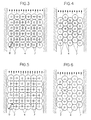
Gemäss DE-A1 44 30 302 ist die von den Prallstrahlen beaufschlagte Wand als
Relief mit vorstehenden Buckeln ausgebildet, wobei die Strahlen direkt auf die
hervorstehende Buckel auftreffen (Fig.3). Damit soll die inhomogene Wärmeübertragung
in den Prallstrahlen ausgeglichen und eine homogene Temperaturverteilung
auf der heissen Seite der Wand erzielt werden. Die Buckel sind bei
dieser Anordnung im wesentlichen als Zylinder ausgebildet mit herstellungsbedingt
abgerundeten Kanten. Bei einem weiteren Ausführungsbeispiel (Fig.4)
liegt das Relief in Fom von Rippen vor.
Beide Geometrien haben in Bezug auf den Wärmeübergang keine vorteilhaften
thermischen Randbedingungen. Die Wärme, die über die Oberfläche eines aus
der zu kühlenden Wand hervorstehenden Elementes abgegeben werden kann,
muss zunächst einmal durch dessen Grundfläche und das Material an die
Oberfläche geleitet werden. Dadurch stellt sich im Material des Elementes eine
Temperaturschichtung ein. Diese kann je nach Material und Geometrie dazu
führen, dass an den am weitesten von der Basis des Elementes entfernten Stellen
die Temperaturdifferenz zwischen Fluid und Element so klein wird, dass praktisch
keine Wärmeübertagung mehr stattfindet. According to DE-A1 44 30 302 , the wall impacted by the impact beams is designed as a relief with protruding humps, the beams hitting the protruding humps directly (FIG. 3). This is to compensate for the inhomogeneous heat transfer in the impact jets and to achieve a homogeneous temperature distribution on the hot side of the wall. In this arrangement, the humps are essentially designed as cylinders with rounded edges due to the manufacturing process. In a further exemplary embodiment (FIG. 4), the relief is in the form of ribs.
Both geometries have no advantageous thermal boundary conditions with regard to heat transfer. The heat that can be given off over the surface of an element protruding from the wall to be cooled must first be conducted to the surface through its base area and the material. This results in a temperature stratification in the material of the element. Depending on the material and geometry, this can lead to the temperature difference between the fluid and the element becoming so small at the points furthest from the base of the element that practically no heat transfer takes place.
Zur Vermeidung dieser Nachteile ist in der prioritätsälteren Anmeldung EP 0 889
201 angeregt worden, eine solche Prallanordnung derartig zu konfigurieren, dass
die Prallstrahlen stets zwischen die buckelförmigen Rauhigkeitselemente gerichtetTo avoid these disadvantages, EP 0 889 is in the earlier priority application
201 has been encouraged to configure such a baffle arrangement in such a way that
the impact beams are always directed between the hump-shaped roughness elements
sind, und die bildende Kurve dieser hervorstehenden Buckel die Kontur eines
Rotationsparaboloiden einnimmt. Eine solche Konfiguration gewährleistet eine
hohe thermische Wirksamkeit der auf die Wand auftreffenden Prallstrahlen in
mehrfacher Hinsicht; zum einen liegt im Auftreffbereich der Strahlen ein hoher
Wärmeübergang vor, zum anderen sorgt eine ungehinderte Abströmung des
Prallmediums über die strömungsoptimierte Buckelfläche für sehr hohe
Wärmeübergangswerte.and the forming curve of this protruding hump is the contour of a
Paraboloid of revolution. Such a configuration ensures one
high thermal effectiveness of the impact beams hitting the wall
in several ways; on the one hand, there is a high one in the area where the rays strike
Heat transfer before, on the other hand ensures an unhindered outflow of the
Impact medium over the flow-optimized hump area for very high
Heat transfer rates.
Die Rauhigkeitselemente sind entweder auf die zu kühlende Wand aufgesetzt
oder als einheitliches Gussteil ausgeführt. Im letzteren Falle wird die günstige
Geometrie dieser Struktur durch einen erhöhten Herstellungsaufwand erkauft.The roughness elements are either placed on the wall to be cooled
or executed as a uniform casting. In the latter case, the cheap one
Geometry of this structure bought by an increased manufacturing effort.
Des weiteren sind umfangreiche Untersuchungen zu lokalen Wärmeübergangszahlen von Einzel-Prallstrahlen und Feldern von Prallstrahlen auf ebene Oberflächen sowie auf einfach gekrümmte Oberflächen bekannt.Furthermore, there are extensive studies on local heat transfer numbers of single impact beams and fields of impact beams on flat surfaces as well as on simply curved surfaces.
Schliesslich ist es im Gebiet der Turbomaschinen aus Untersuchungen zur Kühlung von gekrümmten Schaufelvorderkanten an sich bekannt, die dem Prallstrahl zugekehrte Seite der Wand als Wanne auszubilden, wobei ein Prallstrahl senkrecht auf den Wannenboden auftrifft. Jedoch haben diese bekannten Wandteile eine gleichbleibende Wandstärke, so es sich letztlich um das gleiche Prinzip handelt, wie die Prallkühlung einer Wand mit beidseitig ebenen Flächen. Finally, in the field of turbomachinery, it is known per se from investigations for cooling curved blade leading edges to design the side of the wall facing the impact jet as a trough, with an impact jet hitting the trough bottom perpendicularly. However, these known wall parts have a constant wall thickness, so it is ultimately the same principle as the impingement cooling of a wall with flat surfaces on both sides.
Der Erfindung liegt die Aufgabe zugrunde, eine Prallanordnung zu schaffen, bei welcher die Rauhigkeitselemente bezüglich des Herstellungsprozesses und der thermischen Wirksamkeit optimiert sind. Ausgehend von den oben erwähnten Lösungsvorschlägen des Standes der Technik soll dies durch Schaffung einer neuen Geometrie der Reliefstruktur erreicht werden. The invention has for its object to provide a baffle arrangement which the roughness elements related to the manufacturing process and the thermal effectiveness are optimized. Starting from the above Proposed solutions of the prior art should do this by creating a new geometry of the relief structure can be achieved.
Erfindungsgemäss wird dies bei einer Prallanordnung der eingangs genannten Art
mit den kennzeichenden Merkmalen des Patentanspruchs 1 erreicht. Günstige
Weiterbildungen der Erfindung ergeben sich aus den Unteransprüchen.According to the invention, this is the case with a baffle arrangement of the type mentioned
achieved with the characterizing features of
Die Vorteile der neuen Massnahme sind unter anderem darin zu sehen, dass infolge der nahezu isothermen Oberfläche eine hohe Pin-Effektivität erzielt wird und dass auch an den nicht parallel zur mit den Prallstrahlen zu beaufschlagenden Wand gerichteten Flächen ein hoher Wärmeübergang vorliegt. Darüber hinaus ist wegen des Fehlens von scharfen Kanten und kleinen Radien mit einer einfachen und kostengünstigen Fertigung zu rechnen. Die Geometrie ist leicht auszuformen und damit gut giessbar; sie ist fehlertolerant und gestattet grosse Masstoleranzen. Infolge der Symmetrie der Wannen ist deren Anordnung unabhängig von der Anströmung durch das umgelenkte Prallmittel. Schliesslich haben die neuen Wannen auch niedrige Druckverluste zur Folge.The advantages of the new measure can be seen in the fact that Due to the almost isothermal surface, a high pin effectiveness is achieved and that also on those not parallel to the impact beams Wall-facing surfaces have a high heat transfer. About that addition, due to the lack of sharp edges and small radii with a simple and inexpensive production. The geometry is light form and thus easily pourable; it is fault tolerant and allows large ones Dimensional tolerances. Due to the symmetry of the tubs, their arrangement is regardless of the flow from the deflected impact medium. Finally the new tubs also result in low pressure drops.
Zudem können die Stege zwischen den Wannen mit Abstandshaltern zur strahlerzeugenden Platte versehen werden oder je nach Ausbildung dieser Platte sogar direkt als Abstandshalter benutzt werden, wenn die Platte auf den Stegen aufliegt. In addition, the webs between the tubs can be spaced beam generating plate or depending on the design of this plate can even be used directly as a spacer when the plate is on the webs rests.
Schliesslich werden durch die neue Massnahme neben einer Optimierung der thermischen auch die mechanischen Eigenschaften der zu kühlenden Wand verbessert.Finally, in addition to optimizing the thermal also improves the mechanical properties of the wall to be cooled.
In der Zeichnung sind mehrere Ausführungsbeispiele der Erfindung vereinfacht dargestellt. Es zeigen:
- Fig. 1
- einen Längsschnitt durch eine Prallströmungs-Anordnung;
- Fig. 2a-c
- verschiedene Wannen-Geometrien
- Fig. 3
- eine Vierer-Anordnung von Wannen;
- Fig. 4
- eine verschachtelte Sechser-Anordnung von Wannen;
- Fig. 5
- eine Variante der Vierer-Anordnung nach Fig.3;
- Fig. 6
- eine Variante der Sechser-Anordnung nach Fig.4;
- Fig. 7
- eine prallgekühlte Gasturbinenschaufel;
- Fig. 8
- ein Ausführungsbeispiel mit Prallrohren statt Prallöffnungen.
- Fig. 9
- ein Ausführungsbeispiel mit strukturiertem Träger.
- Fig. 1
- a longitudinal section through an impingement flow arrangement;
- 2a-c
- different tray geometries
- Fig. 3
- a set of four tubs;
- Fig. 4
- an interleaved array of six tubs;
- Fig. 5
- a variant of the arrangement of four according to Figure 3;
- Fig. 6
- a variant of the six arrangement according to Figure 4;
- Fig. 7
- an impact-cooled gas turbine blade;
- Fig. 8
- an embodiment with baffle tubes instead of baffle openings.
- Fig. 9
- an embodiment with a structured carrier.
Es sind nur die für das Verständnis der Erfindung wesentlichen Elemente gezeigt. In den verschiedenen Figuren sind die funktionsgleichen Elemente mit denselben Bezugszeichen versehen. Die Strömungsrichtung der Medien sind mit Pfeilen bezeichnet.Only the elements essential for understanding the invention are shown. In the different figures, the functionally identical elements are the same Provide reference numerals. The flow direction of the media are with arrows designated.
Nachstehend wird die Prallströmung als Prallkühlung bezeichnet, wie sie beispielsweise zur Kühlung von umströmten heissen Turbomaschinen-Komponenten wie Gasturbinenschaufeln oder Brennkammerwandungen Anwendung finden kann.In the following, the impingement flow is referred to as impingement cooling, for example for cooling hot turbomachine components with flow such as gas turbine blades or combustion chamber walls are used can.
In Fig. 1 ist das beispielsweise mittels Kühlluft 5 zu kühlende Wandteil mit 3
bezeichnet. Es handelt sich hier um eine ebene Wand, welche auf der Aussenseite
von einem durch die Pfeile 6 bezeichneten heissen Medium umströmt wird.
Entsprechend eben ist auch der kühlluftseitige Träger 1 ausgebildet. Er ist im
gezeigten Fall mit gleichbleibendem Abstand 20 mittels geeigneter, nicht dargestellter
Mittel mit der Wand 3 befestigt. Der Träger weist eine Mehrzahl von
Prallöffnungen 2 auf und kann als einfaches Lochblech konzipiert sein.In FIG. 1, the wall part to be cooled, for example by means of cooling
Auf der Innenseite ist die zu kühlende Wand 3 mit einer Anzahl nebeneinanderangeordneter
Wannen 4 versehen. Diese Wannen weisen im Beipielsfall die Form
von Kalotten auf. Der Abstand der Wannen zueinander ist so gewählt, dass sich
ein schmaler Steg 7 zwischen den benachbarten Wannen-Wandungen ergibt.
Gegenüber einer ebenen Ausbildung hat die kalottenförmige Konfiguration der zu
kühlenden Wand eine beträchtliche Vergrösserung der wärmeübertragenden
Fläche und damit des Wärmestromes zur Folge.On the inside is the
Die dem Prallstrahl abgekehrte Seite des Wandteiles 3 ist im Beipielsfall eben
ausgebildet. Es versteht sich, dass diese dem Prallstrahl abgekehrte Seite genau
so gut mit einer Krümmung versehen sein kann, wobei der Krümmungsradius
dann jedoch sehr viel grösser sein sollte als jener der Kalotte.The side of the
Das zu kühlende Wandteil ist mitsamt Wannen vorzugsweise einteilig vergossen. Unabhängig vom Herstellungsprozess ergibt sich ein Gebilde von hoher Festigkeit. Die strukturierte von den Prallstrahlen beaufschlagte Fläche trägt - bezogen auf die Grundstärke a der Wand 3 - massgeblich zur Steifigkeit des Gesamtsystems bei. Dies kann einerseits zu einer vorteilhaften Reduzierung der Grundwandstärke a führen, wenn eine möglichst geringe Masse des Systems gefordert ist. Oder aber andererseits kann bei Beibehaltung der Grundstärke a und konstanter mechanischer Beanspruchung die Fluidtemperatur auf der heissen Seite entsprechend erhöht werden. Schliesslich ist bei Beibehaltung der Grundstärke a und der Temperatur des heissen Fluids durch die neue Massnahme mit einer Verlängerung der Haltbarkeit des Systems zu rechnen.The wall part to be cooled is preferably cast in one piece together with the tubs. Regardless of the manufacturing process, a structure of high strength results. The structured surface impacted by the impact beams carries - related to the basic thickness a of wall 3 - decisive for the rigidity of the overall system at. On the one hand, this can lead to an advantageous reduction in the base wall thickness a lead if the smallest possible mass of the system is required is. Or on the other hand, while maintaining the basic strength a and constant mechanical stress the fluid temperature on the hot side be increased accordingly. Finally, while maintaining the basic strength a and the temperature of the hot fluid with the new measure Extend the life of the system.
Je Wanne ist ein Prallstrahl vorgesehen, wobei dieser aus der Prallöffnung 2
austretende Prallstrahl in der Regel zumindest annähernd senkrecht auf den
Wannenboden auftrifft. Beim Auftreffen wird der Prallstrahl auf die übrige Prallfläche,
d.h. die Wände der Wanne, umgelenkt. Das beim Umströmen der Kalotte
erwärmte Kühlmittel strömt danach in den Freiraum zwischen Träger und Wandteil
ab, wobei die sich einstellende Querströmung auch noch zur Kühlung der Stege 7
beiträgt.An impact jet is provided for each trough, this exiting from the
In Fig. 2 sind verschiedene weiter mögliche Geometrien von Wannen erläutert. Da es sich um symmetrisch aufgebaute Elemente handelt, ist jeweils nur eine Wannenhälfte dargestellt.Various further possible geometries of troughs are explained in FIG. 2. There there are only symmetrically constructed elements Half of the tub shown.
Statt der Kalotte nach Fig. 1, zu dessen Erzeugung ein Kreis um seinen Durchmesser gedreht wird, zeigt Fig. 2a eine Ellipsenform. Wie bei der Kugelkalotte wird auch diese Form durch Rotation des entsprechenden Ausschnittes um die Achse U erzeugt.Instead of the spherical cap according to FIG. 1, a circle around its diameter is used to produce it 2 a shows an elliptical shape. As with the spherical cap this shape is also rotated around the corresponding section Axis U generated.
Fig. 2b zeigt eine einer verkürzten Zykloide angenäherte Form, die durch Rotation des entsprechenden Ausschnittes um eine gegenüber der Prallstrahlachse parallel versetzte Achse U erzeugt wurde. Es versteht sich, dass bei dieser Form der Prallstrahl zur vollen Wirksamkeit genau auf den Wendepunkt auftreffen muss.2b shows a shape approximated to a shortened cycloid by rotation the corresponding section around a parallel to the impact beam axis offset axis U was generated. It is understood that with this form of Impact jet must hit the inflection point for full effectiveness.
Fig. 2c schliesslich zeigt eine trapezförmige Wanne mit ebenem Boden, deren Wandungen gerade oder gekrümmt (wie dargestellt) ausgeführt sein können. Fig. 2c finally shows a trapezoidal trough with a flat bottom, the Walls can be straight or curved (as shown).
Unabhängig von der gewählten Wannen-Geometrie entsteht im Verbund eine wabenförmige Struktur, deren Einzelelementen jeweils ein Freistrahl zugeordnet ist. Dieser ist so positioniert, dass sein Kern unter den gegebenen Randbedingungen - u.a. dem Querstrom des abströmenden Kühlmediiums von benachbarten Elementen - einen Staupunkt im unteren Bodenbereich der Wannen bewirkt. Dabei kann die Achslage des Freistrahles von der Drehachse des Rotationskörpers abweichen.Regardless of the selected tub geometry, a composite is created honeycomb structure, the individual elements of which are each assigned a free jet is. This is positioned so that its core under the given boundary conditions - i.a. the cross flow of the outflowing cooling medium from neighboring elements - a stagnation point in the lower floor area of the Tubs. The axis position of the free jet can change from the axis of rotation of the rotating body.
Die jeweils zu wählende Geometrie soll den Wärmestrom derart beeinflussen, dass die Oberflächentemperatur mit zunehmendem Abstand von der Basis nur unwesentlich abnimmt und somit ein nahezu konstanter Wärmestrom durch die gesamte Oberfläche fliessen kann.The geometry to be selected should influence the heat flow in such a way that the surface temperature only increases with increasing distance from the base decreases insignificantly and thus an almost constant heat flow through the entire surface can flow.
Da infolge dieser Geometrie überall eine ausreichende Temperaturdifferenz gewährleistet ist, kann die gesamte Oberflläche Wärme übertragen. Darüberhinaus ist der Wärmeübergangskoeffizient auf der Oberfläche etwa gleich demjenigen, der auf der Basisfläche ohne die Wanne vorherrschen würde. Dies wiederum im Gegensatz zu den bekannten Elementen mit senkrecht zur Wand verlaufenden Flächen, bei denen mit erheblich reduziertem Wärmeübergangskoeffizient zu rechnen ist.As a result of this geometry there is a sufficient temperature difference everywhere is guaranteed, the entire surface can transfer heat. Furthermore the heat transfer coefficient on the surface is approximately equal to that that would prevail on the base surface without the tub. This again in contrast to the known elements with perpendicular to the wall running surfaces where the heat transfer coefficient is significantly reduced is to be expected.
Aufgrund der neuen Geometrie der Wannen sind nun mehrere unterschiedliche Anordnungsmöglichkeiten gegeben, die in Funktion des gewünschten Wärmeübertragung und/oder der tolerierbaren Druckverluste auszuwählen sind.Due to the new geometry of the tubs, there are now several different ones Arrangement options are given, depending on the desired heat transfer and / or the tolerable pressure losses are to be selected.
Bezogen auf die Querströmung im Bereich der Basis lassen sich grundsätzlich zwei Anordnungen unterscheiden. Relative to the cross flow in the area of the base can basically distinguish two arrangements.
Die Prallöffnungen 2 und die Wannen 4 können im Verbund entweder in Reihe
angeordnet sein gemäss Fig. 3 oder sie können gegeneinander versetzt sein,
beispielsweise um eine halbe Teilung gemäss Fig. 4. Daraus resultieren Anordnungen,
die entweder quadratisch oder sechseckig sind, wie die gestrichelten
Linien in den Fig. 3 resp. 4 zeigen.The
Vorzugsweise werden die Wannen 4 an den Kreuzungspunkten dieser
gestrichelten Linen angeordnet. Wie Fig. 3 zeigt, sind in der Reihenanordnung
direkt benachbarte Wannen ohne Zwischenräume, d.h. ohne Stege angeordnet.
Dennoch werden bei dieser Ausführung in der Mitte von jeweils 4 Wannen relativ
grosse Stege 7gebildet. Auf diesen Stegen können Abstandhalter zum Träger
vorgesehen sein, wobei diese Abstandhalter auch integral mit der Wand 3 vergossen
sein können.The
In der versetzten Anordnung nach Fig. 4 sind sechs symmetrische Elemente mit einer danebenliegenden Sechseranordnung ineinanderverschachtelt. Hier ist zu erkennen, dass bei gleicher Wannengrösse die Oberfläche gegenüber der Anordnung nach Fig. 3 insofern vergrössert wird , als die nunmehr zwischen je drei Wannen gebildeten Stege bedeutend kleinere Ausmasse annehmen.4 are six symmetrical elements with nested in a six-sided arrangement. Here is too recognize that with the same tub size the surface compared to the The arrangement according to FIG. 3 is enlarged insofar as that between each three troughs formed by footbridges assume significantly smaller dimensions.
Die Anordnung nach Fig. 5 entspricht in ihrer Geometrie jener der Fig. 3. Die
Grösse und der gegenseitige Abstand der Prallöffnungen 2 sind gleich gewählt.
Hingegen wurde der Durchmesser D der Wannen vergrössert, was zu einer
Verschneidung benachbarter Wannen und zu kleineren Stegen 7 führt. Diese
Lösung kann fertigungsbedingte Vorteile aufweisen und kann je nach Wahl des
Durchmessers zu flacheren Wannen führen.The geometry of the arrangement according to FIG. 5 corresponds to that of FIG. 3
The size and the mutual distance between the
Die Anordnung nach Fig. 6 entspricht in ihrer Geometrie jener der Fig. 4. Die
Grösse und der gegenseitige Abstand der Prallöffnungen 2 sind wiederum gleich
gewählt. Hingegen wurde der Durchmesser D der Wannen vergrössert, was zu
einer Verschneidung benachbarter Wannen und zu extrem kleinen Stegen führt.
Man erkennt hier, dass ab einem gewissen Wannen-Durchmesser überhaupt
keine Stege mehr gebildet werden.The geometry of the arrangement according to FIG. 6 corresponds to that of FIG. 4. The
The size and the mutual distance between the
In Fig. 7 ist als Beispiel eines zu kühlenden Bauteils eine Gasturbinenschaufel 16
gezeigt. Die Träger mit den Prallöffnungen 2 sind als mehr oder weniger rohrförmige
Einsätze 17A, 17B und 17C konzipiert und im hohlen Inneren der Schaufel
angeordnet. Diese Einsätze sowie die mit den Wannen 4 versehene Schaufelwand
können als Gussteil ausgeführt sein. Sie können desgleichen als drucktragenes
Gebilde ausgestaltet sein für Innendrücke, die bis zum Doppelten des in
der eigentlichen Prallzone herrschenden Druckes betragen können.7 shows a
Im Falle einer Leitschaufel erfolgt die Einströmung des Kühlmittels in die Einsätze
in der Regel vom Schaufelfuss her gegen die Schaufelspitze hin. Die Prallöffnungen
2 und die Wannen 4 sind über die Schaufelhöhe und den Schaufelumfang in
erforderlichem Abstand zueinander gestaffelt. die Einsätze 17A-C können vom
Kühlmittel einzeln oder in Serie durchströmt werden.In the case of a guide vane, the coolant flows into the inserts
usually from the blade root towards the tip of the blade. The
Das gas- oder dampfförmige Kühlmedium kann in den mehreren Einsätzen im
geschlossenen Kreis zirkuliert werden, d.h. es wird nach vollzogener Kühlung
wieder über den Schaufelfuss abgezogen. Das von den gekühlten Wandteilen
abströmende Kühlmedium kann jedoch aus der Schaufel heraus in den
Strömungskanal austreten. Dies geschieht vorzugsweise an jener Stelle der
Schaufel, an welcher der tiefste Aussendruck vorherrscht. In der Regel wird man
das Kühlmittel somit an der Hinterkante 18 der Schaufel austreten lassen.The gaseous or vaporous cooling medium can be used in several applications
closed circle, i.e. it becomes after cooling
pulled back over the blade root. That from the cooled wall parts
outflowing cooling medium can, however, out of the blade in the
Exit the flow channel. This is preferably done at that point in the
Bucket at which the lowest external pressure prevails. Usually you will
the coolant can thus escape at the
Fig. 8 zeigt ein Ausführungsbeispiel, bei welchem derTräger ebenfalls flächenförmig
ist und mit einer Vielzahl, hier äquidistanter und in Reihen angeordneter
Prallrohre 21 versehen ist. Deren Einlauf 22 entspricht einer Prallöffnung und ist
bündig mit der Trägeroberfläche. Die Prallrohre weisen einen konischen Innenkanal
mit stetiger Verengung in Strömungsrichtung auf. Der engste Querschnitt
der Prallrohre liegt damit an der Mündung 23. Mit ihrer Mündung 23 sind die Prallrohre
senkrecht gegen das zu kühlende Wandteil gerichtet. Die Mündung befindet
sich im Prallabstand 25 zur Wand. Im Beispielsfall beträgt das Verhältnis dieses
Prallabstandes zum engsten Durchmesser der Prallrohre etwa 1. Es ist ersichtlich,
dass die nach dem Aufprall abgelenkte Kühlluft in die freien Zwischenräume 21
zwischen den Prallrohren abströmen kann, ohne dabei benachbarte Prallstrahlen
zu stören. Das lichffreie Mass des Zwischenraumes ist bei senkrechter
Ausrichtung der Prallrohre durch deren Länge gegeben. Im Gegensatz zu den
Kühlluftstrahlen, die über ein Lochblech erzeugt werden bietet diese Lösung den
Vorteil der freien Gestaltung des Verhältnisses von Strahlabstand zum
Strahldurchmesser welches sich durchaus über einen Bereich von 0.1 bis 4
erstrecken kann.Fig. 8 shows an embodiment in which the carrier is also sheet-like
is and with a variety, here equidistant and arranged in
Bisher wurden die Wannen stets als rotationssymmetrische Körper betrachtet, die durch Drehen des entsprechenden Abschnittes um 360° entstanden sind. In Abweichung hierzu ist es selbstverständlich auch möglich, die Wannen rinnenförmig zu gestalten, wobei allerdings die Oberflächenvergrösserung etwas kleiner ausfällt als mit rotationssymmetrischen Wannen. Zur Erzeugung einer Rinne wird der entsprechende Abschnitt nicht um eine Achse U gedreht, sondern längs einer vorzugsweise geraden Achse U verschoben. Hierdurch entstehen an der zu kühlenden Fläche Längsrinnen mit Kreis-, Ellipsen- oder Trapezform. Bei dieser Konfiguration tritt der Stabilisierungseffet der oberflächenvergrössernden Struktur in einer definierten Richtung auf. Die Prallstrahlen sollen bei dieser Lösung ebenfalls auf den Grund der Rinne auftreffen. Man wird hier eine gewisse Anzahl Prallstrahlen in der Längserstreckung der Rinne vorsehen, wobei der zu wählenden Teilung der Prallstrahlen je nach der erforderlichen Kühlleistung Aufmerksamkeit zu schenken ist. Dabei hat es sich gezeigt, dass eine - beispielsweise fertigungsbedingte - fehlerhafte Anordnung der Prallstrahlen nur einen unwesentlichen Einfluss auf die Wirksamkeit des Gesamtsystemes hat. So far, the tubs have always been viewed as rotationally symmetrical bodies that by rotating the corresponding section through 360 °. In Deviation from this, it is of course also possible for the troughs to be trough-shaped to design, although the surface enlargement somewhat smaller fails as with rotationally symmetrical tubs. To create a gutter the corresponding section is not rotated about an axis U, but along one preferably straight axis U shifted. This gives rise to the cooling surface longitudinal channels with circular, elliptical or trapezoidal shape. At this Configuration occurs the stabilizing effect of the surface-enlarging structure in a defined direction. The impact beams are intended for this solution also hit the bottom of the gutter. You become a certain number here Provide impact beams in the longitudinal direction of the channel, the one to be selected Splitting the impact jets depending on the cooling capacity required is to be given. It has been shown that one - for example manufacturing-related - incorrect arrangement of the impact beams only an insignificant one Has an impact on the effectiveness of the overall system.
Wie bereits oben erwähnt, ist der einfachste Fall für den Träger 1 eine ebene
Lochplatte. Gemäss Fig. 9 kann jedoch auch eine Lochplatte mit kalottenartigen
Senken 26 zur Anwendung gelangen. Die Senken enthalten jeweils die Prallöffnungen
2, wobei erkennbar ist, dass mit dieser Lösung ein einfaches Mittel gegeben
ist, den Prallabstand 25 zu beeinflussen. Für den Fall, dass die Wannen rinnenförmig
ausgebildet sind, bietet es sich an, auch die Senken 26 als Rinnen zu
gestalten. Diese müssen nicht notwendigerweise in der gleichen Richtung verlaufen
wie die Wannen. Sie können beliebig in einem Winkel zwischen 0° und 90°
zur Wannenrichtung oder zur Richtung des Kühlstromes 6 verlaufen. Die
zwischen den Senken vorhandenen Zwischenräume 27 können dadurch zur
gezielten Abfuhr des Kühlmediums benutzt werden. Darüberhinaus bietet der
unterschiedliche Richtungsverlauf die Möglichkeit, die rinnenförmige Senke 26
direkt auf den Stegen 7 der Wanne abzustützen (nicht dargestellt).As already mentioned above, the simplest case for the
Selbstverständlich ist die Erfindung nicht auf die gezeigten und beschriebenen
Beispiele beschränkt. Es versteht sich, dass je nach Erfordernissen die Anzahl
und Teilung der Prallöffnungen 2 oder -rohre 21, sowie Länge und Form der letzteren,
fallweise optimiert werden können. Auch in der Wahl des Kühlmittels, dessen
Druckes und dessen Weiterverwendung nach der Kühltätigkeit setzt die
Erfindung keine Schranken.Of course, the invention is not limited to that shown and described
Examples limited. It is understood that depending on the requirements, the number
and division of the
Schliesslich wird der Fachmann erkennen, dass die Erfindung nicht nur zum Zweck der Kühlung von Wandteilen von Maschinen, Apparaten oder allgemein Anlagen angewendet werden kann, sondern genau so gut zu deren Heizung. Beispiele für eine solche Anwendung des flächigen Heizens bilden z.B. das Trocknen von Papier, das Schmelzen und Verkleben von Kunststoffen, das Enteisen von Tragflügeln an Flugzeugen usw. Finally, those skilled in the art will recognize that the invention is not only for Purpose of cooling wall parts of machines, apparatus or in general Plants can be used, but just as well for heating them. Examples of such an application of flat heating are e.g. the Drying paper, melting and gluing plastics, the Defrosting wings of aircraft, etc.
- 11
- Trägercarrier
- 22
- Prallöffnungimpact aperture
- 33
- Wandteilwall part
- 44
- Wannetub
- 55
- Kühlluftcooling air
- 66
- Heissgashot gas
- 77
- Stegweb
- aa
- Grundstärke a von 3Basic strength a of 3
- UU
- Rotationsachseaxis of rotation
- DD
- Durchmesser der WanneDiameter of the tub
- HH
- Höhe der WanneHeight of the tub
- R1R1
- Radius der WanneRadius of the tub
- 1616
- GasturbinenschaufelGas turbine blade
- 17A,B,C17A, B, C
- Einsatzcommitment
- 1818
- Hinterkantetrailing edge
- 2020
- Trägerabstandcarrier spacing
- 2121
- PrallrohrVertical pipe
- 2222
- Einlaufenema
- 2323
- Mündungmuzzle
- 2525
- Prallabstandbaffle spacing
- 2626
- Senkedepression
- 2727
- Zwischenraumgap
Claims (1)
- Impingement arrangement, in which a plurality of impingement orifices (2) are arranged areally in a plane or curved carrier (1) and the carrier (1) is arranged at a distance from a wall part (3), whose impingement area, to be cooled or heated, is designed as a relief with a number of troughs (4) arranged next to one another, at least one impingement jet per trough (4) being provided, which impingement jet strikes the trough base at least approximately perpendicularly, and that side of the wall part (3) which is remote from the impingement jet being of at least roughly plane design, characterized in that the troughs (4) have the cross-sectional shape of a circle segment, of an ellipse or of a shortened cycloid and are of rotationally symmetrical or, by means of a displacement along a straight axis, longitudially extended design.
Priority Applications (4)
| Application Number | Priority Date | Filing Date | Title |
|---|---|---|---|
| DE59709158T DE59709158D1 (en) | 1997-09-30 | 1997-09-30 | Impact arrangement for a convective cooling or heating process |
| EP97810718A EP0905353B1 (en) | 1997-09-30 | 1997-09-30 | Impingement arrangement for a convective cooling or heating process |
| JP10276133A JPH11159301A (en) | 1997-09-30 | 1998-09-29 | Flow buffer system for wall part |
| US10/002,633 US20020062945A1 (en) | 1997-09-30 | 2001-12-05 | Wall part acted upon by an impingement flow |
Applications Claiming Priority (1)
| Application Number | Priority Date | Filing Date | Title |
|---|---|---|---|
| EP97810718A EP0905353B1 (en) | 1997-09-30 | 1997-09-30 | Impingement arrangement for a convective cooling or heating process |
Publications (2)
| Publication Number | Publication Date |
|---|---|
| EP0905353A1 EP0905353A1 (en) | 1999-03-31 |
| EP0905353B1 true EP0905353B1 (en) | 2003-01-15 |
Family
ID=8230407
Family Applications (1)
| Application Number | Title | Priority Date | Filing Date |
|---|---|---|---|
| EP97810718A Expired - Lifetime EP0905353B1 (en) | 1997-09-30 | 1997-09-30 | Impingement arrangement for a convective cooling or heating process |
Country Status (4)
| Country | Link |
|---|---|
| US (1) | US20020062945A1 (en) |
| EP (1) | EP0905353B1 (en) |
| JP (1) | JPH11159301A (en) |
| DE (1) | DE59709158D1 (en) |
Cited By (3)
| Publication number | Priority date | Publication date | Assignee | Title |
|---|---|---|---|---|
| US11859823B2 (en) | 2022-05-13 | 2024-01-02 | General Electric Company | Combustor chamber mesh structure |
| US11859824B2 (en) | 2022-05-13 | 2024-01-02 | General Electric Company | Combustor with a dilution hole structure |
| US11867398B2 (en) | 2022-05-13 | 2024-01-09 | General Electric Company | Hollow plank design and construction for combustor liner |
Families Citing this family (65)
| Publication number | Priority date | Publication date | Assignee | Title |
|---|---|---|---|---|
| US6589600B1 (en) * | 1999-06-30 | 2003-07-08 | General Electric Company | Turbine engine component having enhanced heat transfer characteristics and method for forming same |
| EP1409926B1 (en) * | 1999-08-03 | 2004-11-03 | Siemens Aktiengesellschaft | Baffle cooling device |
| US6164914A (en) * | 1999-08-23 | 2000-12-26 | General Electric Company | Cool tip blade |
| US6302185B1 (en) * | 2000-01-10 | 2001-10-16 | General Electric Company | Casting having an enhanced heat transfer surface, and mold and pattern for forming same |
| EP1136651A1 (en) * | 2000-03-22 | 2001-09-26 | Siemens Aktiengesellschaft | Cooling system for an airfoil |
| WO2001071164A1 (en) * | 2000-03-22 | 2001-09-27 | Siemens Aktiengesellschaft | Reinforcement and cooling structure of a turbine blade |
| US20020061045A1 (en) * | 2000-11-21 | 2002-05-23 | Access Laser Company | Portable low-power gas discharge laser |
| GB2420156B (en) | 2004-11-16 | 2007-01-24 | Rolls Royce Plc | A heat transfer arrangement |
| FR2893080B1 (en) * | 2005-11-07 | 2012-12-28 | Snecma | COOLING ARRANGEMENT OF A DAWN OF A TURBINE, A TURBINE BLADE COMPRISING IT, TURBINE AND AIRCRAFT ENGINE WHICH ARE EQUIPPED |
| GB0601413D0 (en) * | 2006-01-25 | 2006-03-08 | Rolls Royce Plc | Wall elements for gas turbine engine combustors |
| US7362574B2 (en) * | 2006-08-07 | 2008-04-22 | International Business Machines Corporation | Jet orifice plate with projecting jet orifice structures for direct impingement cooling apparatus |
| JP5029960B2 (en) * | 2008-01-15 | 2012-09-19 | 株式会社Ihi | Internal cooling structure for high temperature parts |
| EP2143883A1 (en) * | 2008-07-10 | 2010-01-13 | Siemens Aktiengesellschaft | Turbine blade and corresponding casting core |
| JP5222057B2 (en) * | 2008-08-08 | 2013-06-26 | 三菱重工業株式会社 | Gas turbine hot section cooling system |
| US7961475B2 (en) | 2008-10-23 | 2011-06-14 | International Business Machines Corporation | Apparatus and method for facilitating immersion-cooling of an electronic subsystem |
| US7944694B2 (en) | 2008-10-23 | 2011-05-17 | International Business Machines Corporation | Liquid cooling apparatus and method for cooling blades of an electronic system chassis |
| US7885070B2 (en) * | 2008-10-23 | 2011-02-08 | International Business Machines Corporation | Apparatus and method for immersion-cooling of an electronic system utilizing coolant jet impingement and coolant wash flow |
| US7983040B2 (en) * | 2008-10-23 | 2011-07-19 | International Business Machines Corporation | Apparatus and method for facilitating pumped immersion-cooling of an electronic subsystem |
| US7916483B2 (en) * | 2008-10-23 | 2011-03-29 | International Business Machines Corporation | Open flow cold plate for liquid cooled electronic packages |
| CH700319A1 (en) * | 2009-01-30 | 2010-07-30 | Alstom Technology Ltd | Chilled component for a gas turbine. |
| US8348613B2 (en) * | 2009-03-30 | 2013-01-08 | United Technologies Corporation | Airflow influencing airfoil feature array |
| US7885074B2 (en) * | 2009-06-25 | 2011-02-08 | International Business Machines Corporation | Direct jet impingement-assisted thermosyphon cooling apparatus and method |
| US8018720B2 (en) * | 2009-06-25 | 2011-09-13 | International Business Machines Corporation | Condenser structures with fin cavities facilitating vapor condensation cooling of coolant |
| US8014150B2 (en) * | 2009-06-25 | 2011-09-06 | International Business Machines Corporation | Cooled electronic module with pump-enhanced, dielectric fluid immersion-cooling |
| US8059405B2 (en) * | 2009-06-25 | 2011-11-15 | International Business Machines Corporation | Condenser block structures with cavities facilitating vapor condensation cooling of coolant |
| US8490679B2 (en) * | 2009-06-25 | 2013-07-23 | International Business Machines Corporation | Condenser fin structures facilitating vapor condensation cooling of coolant |
| US8305755B2 (en) * | 2010-03-04 | 2012-11-06 | Toyota Motor Engineering & Manufacturing North America, Inc. | Power modules, cooling devices and methods thereof |
| US8179677B2 (en) | 2010-06-29 | 2012-05-15 | International Business Machines Corporation | Immersion-cooling apparatus and method for an electronic subsystem of an electronics rack |
| US8345423B2 (en) | 2010-06-29 | 2013-01-01 | International Business Machines Corporation | Interleaved, immersion-cooling apparatuses and methods for cooling electronic subsystems |
| US8351206B2 (en) | 2010-06-29 | 2013-01-08 | International Business Machines Corporation | Liquid-cooled electronics rack with immersion-cooled electronic subsystems and vertically-mounted, vapor-condensing unit |
| US8369091B2 (en) | 2010-06-29 | 2013-02-05 | International Business Machines Corporation | Interleaved, immersion-cooling apparatus and method for an electronic subsystem of an electronics rack |
| US8184436B2 (en) | 2010-06-29 | 2012-05-22 | International Business Machines Corporation | Liquid-cooled electronics rack with immersion-cooled electronic subsystems |
| GB2492374A (en) * | 2011-06-30 | 2013-01-02 | Rolls Royce Plc | Gas turbine engine impingement cooling |
| JP5791406B2 (en) * | 2011-07-12 | 2015-10-07 | 三菱重工業株式会社 | Wing body of rotating machine |
| JP5791405B2 (en) * | 2011-07-12 | 2015-10-07 | 三菱重工業株式会社 | Wing body of rotating machine |
| US9039350B2 (en) * | 2012-01-09 | 2015-05-26 | General Electric Company | Impingement cooling system for use with contoured surfaces |
| ITTO20120519A1 (en) * | 2012-06-14 | 2013-12-15 | Avio Spa | GAS TURBINE FOR AERONAUTICAL MOTORS |
| US8951004B2 (en) * | 2012-10-23 | 2015-02-10 | Siemens Aktiengesellschaft | Cooling arrangement for a gas turbine component |
| US10270220B1 (en) * | 2013-03-13 | 2019-04-23 | Science Research Laboratory, Inc. | Methods and systems for heat flux heat removal |
| EP3008392B1 (en) * | 2013-06-14 | 2019-08-07 | United Technologies Corporation | Gas turbine engine wave geometry combustor liner panel |
| JP5880531B2 (en) * | 2013-12-11 | 2016-03-09 | トヨタ自動車株式会社 | Cooler |
| US9528381B2 (en) * | 2013-12-30 | 2016-12-27 | General Electric Company | Structural configurations and cooling circuits in turbine blades |
| FR3038655B1 (en) * | 2015-07-06 | 2017-08-25 | Snecma | ASSEMBLY COMPRISING A GROOVE CASING AND MEANS FOR COOLING THE CARTER, TURBINE COMPRISING SAID ASSEMBLY, AND TURBOMACHINE COMPRISING SAID TURBINE |
| US20170175577A1 (en) * | 2015-12-18 | 2017-06-22 | General Electric Company | Systems and methods for increasing heat transfer using at least one baffle in an impingement chamber of a nozzle in a turbine |
| US10408073B2 (en) * | 2016-01-20 | 2019-09-10 | General Electric Company | Cooled CMC wall contouring |
| US10352177B2 (en) * | 2016-02-16 | 2019-07-16 | General Electric Company | Airfoil having impingement openings |
| US10738622B2 (en) * | 2016-08-09 | 2020-08-11 | General Electric Company | Components having outer wall recesses for impingement cooling |
| CN106593541B (en) * | 2016-11-17 | 2018-12-25 | 西北工业大学 | A kind of intensifying impact heat transfer unit (HTU) |
| KR20180065728A (en) * | 2016-12-08 | 2018-06-18 | 두산중공업 주식회사 | Cooling Structure for Vane |
| US11101194B2 (en) * | 2016-12-19 | 2021-08-24 | Agency For Science, Technology And Research | Heat sinks and methods for fabricating a heat sink |
| US10494948B2 (en) * | 2017-05-09 | 2019-12-03 | General Electric Company | Impingement insert |
| CN107449308A (en) * | 2017-07-13 | 2017-12-08 | 西北工业大学 | A kind of impinging cooling system with arc-shaped surface boss |
| CN107503801A (en) * | 2017-08-18 | 2017-12-22 | 沈阳航空航天大学 | A kind of efficiently array jetting cooling structure |
| US10837314B2 (en) * | 2018-07-06 | 2020-11-17 | Rolls-Royce Corporation | Hot section dual wall component anti-blockage system |
| DE102018128102A1 (en) * | 2018-11-09 | 2020-05-14 | Lauda Dr. R. Wobser Gmbh & Co. Kg. | Device for extracorporeal temperature control of patients with a separable secondary body |
| DE102018131426A1 (en) * | 2018-12-07 | 2020-06-10 | Lauda Dr. R. Wobser Gmbh & Co. Kg. | Device and method for temperature control |
| US11248790B2 (en) * | 2019-04-18 | 2022-02-15 | Rolls-Royce Corporation | Impingement cooling dust pocket |
| US11131199B2 (en) * | 2019-11-04 | 2021-09-28 | Raytheon Technologies Corporation | Impingement cooling with impingement cells on impinged surface |
| DE102019129835A1 (en) * | 2019-11-06 | 2021-05-06 | Man Energy Solutions Se | Device for cooling a component of a gas turbine / turbo machine by means of impingement cooling |
| US11220916B2 (en) | 2020-01-22 | 2022-01-11 | General Electric Company | Turbine rotor blade with platform with non-linear cooling passages by additive manufacture |
| US11242760B2 (en) | 2020-01-22 | 2022-02-08 | General Electric Company | Turbine rotor blade with integral impingement sleeve by additive manufacture |
| US11248471B2 (en) | 2020-01-22 | 2022-02-15 | General Electric Company | Turbine rotor blade with angel wing with coolant transfer passage between adjacent wheel space portions by additive manufacture |
| US11492908B2 (en) | 2020-01-22 | 2022-11-08 | General Electric Company | Turbine rotor blade root with hollow mount with lattice support structure by additive manufacture |
| KR102502652B1 (en) | 2020-10-23 | 2023-02-21 | 두산에너빌리티 주식회사 | Array impingement jet cooling structure with wavy channel |
| CN113374546A (en) * | 2021-06-27 | 2021-09-10 | 西北工业大学 | Array impact structure based on circular truncated cone and cylindrical bulge |
Family Cites Families (5)
| Publication number | Priority date | Publication date | Assignee | Title |
|---|---|---|---|---|
| GB849255A (en) * | 1956-11-01 | 1960-09-21 | Josef Cermak | Method of and arrangements for cooling the walls of combustion spaces and other spaces subject to high thermal stresses |
| US5016090A (en) * | 1990-03-21 | 1991-05-14 | International Business Machines Corporation | Cross-hatch flow distribution and applications thereof |
| US5321951A (en) * | 1992-03-30 | 1994-06-21 | General Electric Company | Integral combustor splash plate and sleeve |
| FR2723177B1 (en) * | 1994-07-27 | 1996-09-06 | Snecma | COMBUSTION CHAMBER COMPRISING A DOUBLE WALL |
| DE4430302A1 (en) * | 1994-08-26 | 1996-02-29 | Abb Management Ag | Impact-cooled wall part |
-
1997
- 1997-09-30 EP EP97810718A patent/EP0905353B1/en not_active Expired - Lifetime
- 1997-09-30 DE DE59709158T patent/DE59709158D1/en not_active Expired - Lifetime
-
1998
- 1998-09-29 JP JP10276133A patent/JPH11159301A/en active Pending
-
2001
- 2001-12-05 US US10/002,633 patent/US20020062945A1/en not_active Abandoned
Cited By (3)
| Publication number | Priority date | Publication date | Assignee | Title |
|---|---|---|---|---|
| US11859823B2 (en) | 2022-05-13 | 2024-01-02 | General Electric Company | Combustor chamber mesh structure |
| US11859824B2 (en) | 2022-05-13 | 2024-01-02 | General Electric Company | Combustor with a dilution hole structure |
| US11867398B2 (en) | 2022-05-13 | 2024-01-09 | General Electric Company | Hollow plank design and construction for combustor liner |
Also Published As
| Publication number | Publication date |
|---|---|
| EP0905353A1 (en) | 1999-03-31 |
| US20020062945A1 (en) | 2002-05-30 |
| JPH11159301A (en) | 1999-06-15 |
| DE59709158D1 (en) | 2003-02-20 |
Similar Documents
| Publication | Publication Date | Title |
|---|---|---|
| EP0905353B1 (en) | Impingement arrangement for a convective cooling or heating process | |
| EP0889201B1 (en) | Impingement arrangement for a convective cooling or heating process | |
| EP1113145B1 (en) | Blade for gas turbines with metering section at the trailing edge | |
| EP2770260B1 (en) | Gas turbine combustion chamber with impingement effusion cooled shingle | |
| EP0745809B1 (en) | Vortex generator for combustion chamber | |
| DE4430302A1 (en) | Impact-cooled wall part | |
| DE2526277C2 (en) | Cooled gas turbine blade | |
| DE10001109B4 (en) | Cooled shovel for a gas turbine | |
| DE602004007283T2 (en) | HEAT EXCHANGER AND ITS USE | |
| DE102004045923A1 (en) | Flow channel for a heat exchanger comprises rows with structural elements on opposite-lying heat exchanger surfaces that overlap each other | |
| DE2241194A1 (en) | FLOW MACHINE SHOVEL WITH A WING-SHAPED CROSS-SECTIONAL PROFILE AND WITH A NUMBER OF COOLING DUCTS RUNNING IN THE LENGTH DIRECTION OF THE SHOVEL | |
| DE102014100482A1 (en) | Hot gas path component for turbine system | |
| EP3134682A1 (en) | Burner assembly | |
| EP1192333B1 (en) | Component that can be subjected to hot gas, especially a turbine blade | |
| WO2003054356A1 (en) | Thermally loaded component | |
| EP1876391B1 (en) | Heat Exchanger and Method for its Fabrication | |
| DE2127454A1 (en) | Gas turbine | |
| WO2019211427A1 (en) | Aerofoil for a turbine blade | |
| DE112016001691B4 (en) | Turbine blade and gas turbine | |
| WO2010049195A1 (en) | Gas turbine having cooling insert | |
| DE1946667C3 (en) | Speed equalizer for the inflow or outflow opening of a flow channel | |
| EP2031336B1 (en) | Heat exchanger unit for a combustion engine | |
| EP1923652B1 (en) | Tube bundle heat exchanger with a pipe support with integrated cleaning device | |
| EP1046784B1 (en) | Cooled structure | |
| GB1562662A (en) | Tubular heat exchangers and tube bundle for use therein |
Legal Events
| Date | Code | Title | Description |
|---|---|---|---|
| PUAI | Public reference made under article 153(3) epc to a published international application that has entered the european phase |
Free format text: ORIGINAL CODE: 0009012 |
|
| AK | Designated contracting states |
Kind code of ref document: A1 Designated state(s): DE FR GB IT |
|
| RIN1 | Information on inventor provided before grant (corrected) |
Inventor name: HOECKER, RAINER, DR. Inventor name: HAUSLADEN,JOSEF |
|
| 17P | Request for examination filed |
Effective date: 19990903 |
|
| AKX | Designation fees paid |
Free format text: DE FR GB IT |
|
| RAP1 | Party data changed (applicant data changed or rights of an application transferred) |
Owner name: ALSTOM |
|
| 17Q | First examination report despatched |
Effective date: 20011227 |
|
| GRAH | Despatch of communication of intention to grant a patent |
Free format text: ORIGINAL CODE: EPIDOS IGRA |
|
| RTI1 | Title (correction) |
Free format text: IMPINGEMENT ARRANGEMENT FOR A CONVECTIVE COOLING OR HEATING PROCESS |
|
| GRAH | Despatch of communication of intention to grant a patent |
Free format text: ORIGINAL CODE: EPIDOS IGRA |
|
| RAP1 | Party data changed (applicant data changed or rights of an application transferred) |
Owner name: ALSTOM (SWITZERLAND) LTD |
|
| GRAA | (expected) grant |
Free format text: ORIGINAL CODE: 0009210 |
|
| AK | Designated contracting states |
Kind code of ref document: B1 Designated state(s): DE FR GB IT |
|
| PG25 | Lapsed in a contracting state [announced via postgrant information from national office to epo] |
Ref country code: IT Free format text: LAPSE BECAUSE OF FAILURE TO SUBMIT A TRANSLATION OF THE DESCRIPTION OR TO PAY THE FEE WITHIN THE PRESCRIBED TIME-LIMIT;WARNING: LAPSES OF ITALIAN PATENTS WITH EFFECTIVE DATE BEFORE 2007 MAY HAVE OCCURRED AT ANY TIME BEFORE 2007. THE CORRECT EFFECTIVE DATE MAY BE DIFFERENT FROM THE ONE RECORDED. Effective date: 20030115 Ref country code: FR Free format text: LAPSE BECAUSE OF NON-PAYMENT OF DUE FEES Effective date: 20030115 |
|
| REG | Reference to a national code |
Ref country code: GB Ref legal event code: FG4D Free format text: NOT ENGLISH |
|
| REF | Corresponds to: |
Ref document number: 59709158 Country of ref document: DE Date of ref document: 20030220 Kind code of ref document: P |
|
| GBT | Gb: translation of ep patent filed (gb section 77(6)(a)/1977) |
Effective date: 20030318 |
|
| PLBE | No opposition filed within time limit |
Free format text: ORIGINAL CODE: 0009261 |
|
| STAA | Information on the status of an ep patent application or granted ep patent |
Free format text: STATUS: NO OPPOSITION FILED WITHIN TIME LIMIT |
|
| EN | Fr: translation not filed | ||
| 26N | No opposition filed |
Effective date: 20031016 |
|
| REG | Reference to a national code |
Ref country code: DE Ref legal event code: R082 Ref document number: 59709158 Country of ref document: DE Representative=s name: UWE ROESLER, DE |
|
| REG | Reference to a national code |
Ref country code: GB Ref legal event code: 732E Free format text: REGISTERED BETWEEN 20120802 AND 20120808 |
|
| REG | Reference to a national code |
Ref country code: DE Ref legal event code: R082 Ref document number: 59709158 Country of ref document: DE Representative=s name: ROESLER, UWE, DIPL.-PHYS.UNIV., DE Effective date: 20120713 Ref country code: DE Ref legal event code: R081 Ref document number: 59709158 Country of ref document: DE Owner name: GENERAL ELECTRIC TECHNOLOGY GMBH, CH Free format text: FORMER OWNER: ALSTOM (SWITZERLAND) LTD., BADEN, CH Effective date: 20120713 Ref country code: DE Ref legal event code: R081 Ref document number: 59709158 Country of ref document: DE Owner name: ALSTOM TECHNOLOGY LTD., CH Free format text: FORMER OWNER: ALSTOM (SWITZERLAND) LTD., BADEN, CH Effective date: 20120713 |
|
| REG | Reference to a national code |
Ref country code: DE Ref legal event code: R082 Ref document number: 59709158 Country of ref document: DE Representative=s name: ROESLER, UWE, DIPL.-PHYS.UNIV., DE Ref country code: DE Ref legal event code: R081 Ref document number: 59709158 Country of ref document: DE Owner name: GENERAL ELECTRIC TECHNOLOGY GMBH, CH Free format text: FORMER OWNER: ALSTOM TECHNOLOGY LTD., BADEN, CH |
|
| PGFP | Annual fee paid to national office [announced via postgrant information from national office to epo] |
Ref country code: DE Payment date: 20160921 Year of fee payment: 20 Ref country code: GB Payment date: 20160920 Year of fee payment: 20 |
|
| REG | Reference to a national code |
Ref country code: GB Ref legal event code: 732E Free format text: REGISTERED BETWEEN 20170824 AND 20170830 |
|
| REG | Reference to a national code |
Ref country code: DE Ref legal event code: R071 Ref document number: 59709158 Country of ref document: DE |
|
| REG | Reference to a national code |
Ref country code: GB Ref legal event code: PE20 Expiry date: 20170929 |
|
| PG25 | Lapsed in a contracting state [announced via postgrant information from national office to epo] |
Ref country code: GB Free format text: LAPSE BECAUSE OF EXPIRATION OF PROTECTION Effective date: 20170929 |