EP0904848B1 - Procédé et installation de revêtement d'objets en série - Google Patents
Procédé et installation de revêtement d'objets en série Download PDFInfo
- Publication number
- EP0904848B1 EP0904848B1 EP98117999A EP98117999A EP0904848B1 EP 0904848 B1 EP0904848 B1 EP 0904848B1 EP 98117999 A EP98117999 A EP 98117999A EP 98117999 A EP98117999 A EP 98117999A EP 0904848 B1 EP0904848 B1 EP 0904848B1
- Authority
- EP
- European Patent Office
- Prior art keywords
- connecting conduit
- applicator
- displacement means
- conduit
- valve arrangement
- Prior art date
- Legal status (The legal status is an assumption and is not a legal conclusion. Google has not performed a legal analysis and makes no representation as to the accuracy of the status listed.)
- Expired - Lifetime
Links
Images

Classifications
-
- B—PERFORMING OPERATIONS; TRANSPORTING
- B08—CLEANING
- B08B—CLEANING IN GENERAL; PREVENTION OF FOULING IN GENERAL
- B08B9/00—Cleaning hollow articles by methods or apparatus specially adapted thereto
- B08B9/02—Cleaning pipes or tubes or systems of pipes or tubes
- B08B9/027—Cleaning the internal surfaces; Removal of blockages
- B08B9/04—Cleaning the internal surfaces; Removal of blockages using cleaning devices introduced into and moved along the pipes
- B08B9/053—Cleaning the internal surfaces; Removal of blockages using cleaning devices introduced into and moved along the pipes moved along the pipes by a fluid, e.g. by fluid pressure or by suction
- B08B9/055—Cleaning the internal surfaces; Removal of blockages using cleaning devices introduced into and moved along the pipes moved along the pipes by a fluid, e.g. by fluid pressure or by suction the cleaning devices conforming to, or being conformable to, substantially the same cross-section of the pipes, e.g. pigs or moles
-
- B—PERFORMING OPERATIONS; TRANSPORTING
- B05—SPRAYING OR ATOMISING IN GENERAL; APPLYING FLUENT MATERIALS TO SURFACES, IN GENERAL
- B05B—SPRAYING APPARATUS; ATOMISING APPARATUS; NOZZLES
- B05B12/00—Arrangements for controlling delivery; Arrangements for controlling the spray area
- B05B12/14—Arrangements for controlling delivery; Arrangements for controlling the spray area for supplying a selected one of a plurality of liquids or other fluent materials or several in selected proportions to a spray apparatus, e.g. to a single spray outlet
- B05B12/1481—Arrangements for controlling delivery; Arrangements for controlling the spray area for supplying a selected one of a plurality of liquids or other fluent materials or several in selected proportions to a spray apparatus, e.g. to a single spray outlet comprising pigs, i.e. movable elements sealingly received in supply pipes, for separating different fluids, e.g. liquid coating materials from solvent or air
-
- B—PERFORMING OPERATIONS; TRANSPORTING
- B05—SPRAYING OR ATOMISING IN GENERAL; APPLYING FLUENT MATERIALS TO SURFACES, IN GENERAL
- B05B—SPRAYING APPARATUS; ATOMISING APPARATUS; NOZZLES
- B05B15/00—Details of spraying plant or spraying apparatus not otherwise provided for; Accessories
- B05B15/50—Arrangements for cleaning; Arrangements for preventing deposits, drying-out or blockage; Arrangements for detecting improper discharge caused by the presence of foreign matter
- B05B15/55—Arrangements for cleaning; Arrangements for preventing deposits, drying-out or blockage; Arrangements for detecting improper discharge caused by the presence of foreign matter using cleaning fluids
Definitions
- the invention relates to a method according to the preamble of claim 1 and a device for performing a such procedure.
- the invention is particularly suitable for coating systems for example for the series coating of motor vehicle bodies, in which the available paint materials are different Color usually circulate in ring lines which they have via a valve arrangement serving as a color changer and reach a branch line to the application organ, at which is e.g. can be rotary atomizers or also a spray gun that can be operated with the paint changer relatively long hose is connected. Before every color change and even before long breaks in operation must be known the color in the stub line is completely removed become.
- the object of the invention is to specify a method and a device that when pushing out of the coating material by a through the solvent or other pressure medium loaded pig from the connecting line in the direction to the application organ easier than before mixing coating material and avoids pressure medium.
- the invention ensures that, for example, in front of a Color change or a business break or from another Rinsing process necessary for the ongoing Coating cycle used coating material almost can be applied losslessly without having previously Ring line or material supply system are pushed back to have to.
- the result is a substantial saving of Coating material as well as the possibility with appropriate Design of the facility after the completion of a coating cycle almost instantaneously with the next one Start cycle.
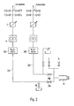
- each color changer is connected via a color pressure regulator 2, a metering pump 4 and a changeover valve 6A or 6B to a valve construction 8 serving as the first “pig station”, which is arranged at the input of a connecting line 12 leading to the application member 10.
- the application member 10 can be a rotary atomizer or, in particular, also a spray gun.
- a further controllable valve arrangement 14 serving as a second “pig station” is provided at the outlet of the connecting line 12.
- Lines for thinner (V) and compressed air (PL) are connected to the changeover valves 6A, 6B and to the valve arrangement 14 as shown via associated valves.
- drain lines RF are connected to the lines between the metering pumps 4 and the changeover valves 6A and 6B and to the valve construction 8, which discard the diluent used during rinsing processes.
- the first “pig station” or valve construction 8 can, for example to accommodate a displacer (not shown) serve according to the proposal of the beginning mentioned patent application 197 09 988.2 a ball of elastic deformable material, whose diameter in undeformed condition equal to or slightly larger than the inside diameter the connecting line 12 is.
- the valve construction 8 is (as also not shown in detail is) switchable between two positions such that the Displacer in the first position the way from Color changer A or B through the changeover valves 6A or 6B in the connecting line 12 releases while he at the second Position by directed into the valve construction 8 Pressure medium can be pressed into the connecting line 12.
- the valve construction 8 similar to that Diaphragm valve containing dead space-free construction Fig. 2 of the mentioned patent application 197 09 988.2 designed his.
- the valve arrangement 14 serving as the second pig station is also designed so that the pig in a valve position the path from the connecting line 12 into the application organ 10 releases and according to the invention in a different valve position is pushed back into the connecting line 12. Instead, it can be sufficient if the pig on the application organ 10 just hits against a stop and through the medium introduced under pressure in the valve arrangement 14, So thinner and / or compressed air can be pushed back into the line is.
- the coating material from a of the two color changers e.g. the color changer A coming through the changeover valve 6A, the valve construction 8, in the the pig in its resting position makes its way into the connecting line 12 releases, and through the valve assembly 14 to the application member 10 promoted.
- the newt or displacer in turn presses the rest of the line Coating material to the application member 10, while this Isolate material from the thinner until it becomes the second Pig station, that is to say reaches the valve arrangement 14, with which the Application process is finished.
- the valve arrangement 14 with which the Application process is finished.
- the switching position is also preferred of the main valve usually formed by the paint needle of the application process and by appropriate Signals reported.
- the pig is passed through the valve arrangement 14 Thinner liquid and / or compressed air back in the valve construction 8 conveyed.
- the thinner can drain the line RF connected to the valve construction 8.
- the color system between the concerned Color changer A or B and the associated switching valve 6A and 6B and the application member 10 rinsed be, the rinsing liquid from the paint system can flow through the line RF at the changeover valve.
- the new color material for a next coating cycle over the other color system from the color changer B to the application member 10 become.
- the one described could Setup even with a single color system without the switching valves 6A and 6B operate.
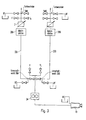
- FIG. 2 differs from that of Fig. 1 essentially in that between the first color changer A and the application member 10 after the color pressure regulator 2 and the dosing pump 4 first as a pig station serving valve construction 28A (corresponding to 8 in Fig. 1), a first connection line 22A and a first valve arrangement 24A (corresponding to 14 in Fig. 1) and between the second Color changer B and the application organ 10 a second as Valve construction 28B serving a pig station, a second Connection line 22B and a second valve assembly 24B are connected to the valve arrangements 24A, 24B lines for thinner and compressed air and on the connecting lines on or near the valve arrangements 24A, 24B drain lines RF connected.
- each of the two connection lines 22A, 22B will be the one therein coating material in the manner described each with its own valve design 28A and 28B positioned displacers to the application organ 10 pressed and from there the displacer moves back according to the invention, the two systems being self-sufficient, i.e. independent of each other can work.
- This facility has the particular advantage that when the pig is moved back in the connecting line 22A and while purging the associated system the other system connected to the color changer already be "preloaded” and with this system without delay the next coating process can be started.
- FIG. 3 Another advantageous variant of the device described is shown in Fig. 3.
- Fig. 1 there are two Color changers A, B optionally via changeover valves 36A or 36B can be coupled to the application member 10.
- Fig. 1 (and to Fig. 2) is only a single metering pump here 34 available, which are in the vicinity of the application member 10 between this and the switching valves 36A, 36B, while two compared to the distance between the application organ 10 and the switching valves 36A, 36B essential longer connecting lines 32A or 32B (corresponding to the Line 12 in Fig. 1) between the switching valves and the both color changers A and B run.
- the positioned in it Displacers are replaced by a sliding means pressurized thinner, compressed air, or instead can be any other print medium and the color changer supplied through the valve SMA or SMB as shown through the relevant connecting line 32A or 32B to the relevant changeover valve 36A or 36B pressed.
- the pig is switched off by the switch valves introduced flushing liquid and / or compressed air to its home position in valve construction 38A or 38B moved back.
- the system from the changeover valve to the color changer through the changeover valve introduced solvent are rinsed on Color changers can be discarded through a drain line RF can.
- the arrangement of the metering pump 34 between those to be pigged Connection lines 32A, 32B and the application member 10 is among others advantageous because only the newts here pure pressed towards the application organ Paint material must be dosed, which is better and more accurate is the dosing of the solvent with which Devices according to Fig. 1 and Fig. 2 the pig and thus the remaining color material to be applied must be promoted. At the same time, there is greater flexibility with regard to of the usable pusher for the pig. Moreover the effort is reduced since one of the two metering pumps 4 1 or FIG. 2 is saved.
- a displacer with which the remaining coating material to be applied by the Connecting line to the application organ is pressed
- a flowable one Use medium that is mixed with the coating material due to its nature and properties such as particularly high surface tension or more appropriate Avoids viscosity, and that by briefly opening a valve from a supply line between the blocked Coating material supply line and the connecting line is initiated before the material change valve assembly the connection from the material supply line for the coating material to be applied next opens.
- This also acts as a pig barrier or insulating medium can, for example, by a provided Valve can be introduced on the color changer or in a separate valve construction according to the pig station 1.
- This valve construction is switchable here between a first position in which one in the valve construction opening channel for the barrier or insulating medium closed by a valve and the way through the valve construction is approved for the coating material, and a second position in which said medium in the Connection line is pressed. It can be useful to open the valve so briefly or in pulses that the Medium introduced only in the form of a small liquid bubble becomes.
- Another possibility of modifying the exemplary embodiments described consists of the pig instead of rinsing liquid and / or compressed air through the after locking the Coating material supply line to be applied next Color material as a print medium through the connecting line to press.
- the cleaning effect of the newt can be sufficient so that no time-consuming rinsing of the Conducting and pressing the next color is required.
Landscapes
- Physics & Mathematics (AREA)
- Fluid Mechanics (AREA)
- Engineering & Computer Science (AREA)
- Mechanical Engineering (AREA)
- Spray Control Apparatus (AREA)
- Cleaning In General (AREA)
- Application Of Or Painting With Fluid Materials (AREA)
Claims (16)
- Procédé pour l'enduction en série de pièces, dans lequel la matière d'enduction est amenée par un conduit d'alimentation de matière d'un dispositif sélecteur de circuit de matière (A, B) et, à partir de là, à travers un conduit de raccordement (12) vers un organe d'application (10), moyennant quoi, avant la fin d'une opération d'enduction, le raccordement entre le conduit d'alimentation de matière et le conduit de raccordement (12) est fermé par le dispositif sélecteur de circuit de matière (A, B), une soupape (V) montée entre un conduit d'alimentation d'un milieu sous pression et le conduit de raccordement est ouverte et la matière d'enduction résiduelle restée dans le conduit de raccordement (12) est transportée par la pression du milieu sous pression jusqu'à l'organe d'application (10) et appliquée par celui-ci, et moyennant quoi la matière d'enduction résiduelle à appliquer est pressée par un organe de refoulement alimenté par le milieu sous pression, qui ne se mélange pas avec la matière d'enduction, à travers le conduit de raccordement (12) jusqu'à l'organe d'application (10), caractérisé en ce que l'organe de refoulement, après l'application de la matière d'enduction résiduelle du conduit de raccordement (12), est replacé dans sa position de repos à l'extrémité du conduit de raccordement (12) opposée à l'organe d'application (10) par un milieu sous pression amené à l'extrémité du conduit de raccordement (12) orientée vers l'organe d'application.
- Procédé selon la revendication 1, caractérisé en ce que l'on utilise comme organe de refoulement un corps de refoulement (refouleur) qui est alimenté par le milieu sous pression.
- Procédé selon la revendication 2, caractérisé en ce que l'on utilise comme corps de refoulement une bille faite d'un matériau élastique déformable dont le diamètre à l'état non déformé est égal ou un peu supérieur au diamètre intérieur du conduit de raccordement (12).
- Procédé selon la revendication 1, caractérisé en ce que l'on utilise comme refouleur un milieu coulant qui, en raison de sa nature et de ses propriétés, évite le mélange avec la matière d'enduction et qui, grâce à l'ouverture momentanée d'une soupape, est introduit par un conduit d'alimentation entre le conduit d'alimentation de matière d'enduction fermé et le conduit de raccordement avant que le dispositif sélecteur de circuit de matière n'ouvre la connexion du conduit d'alimentation de matière pour la matière d'enduction suivante à appliquer.
- Procédé selon l'un des revendications 1 à 4, caractérisé en ce que l'on utilise comme milieu sous pression un liquide de rinçage amené sous pression et/ou de l'air comprimé.
- Procédé selon l'un des revendications 1 à 4, caractérisé en ce que l'on utilise comme milieu sous pression la matière d'enduction suivante à appliquer après la fermeture du conduit d'alimentation de matière d'enduction.
- Procédé selon l'un des revendications 1 à 6, caractérisé en ce que le moment auquel la connexion entre le conduit d'alimentation de matière d'enduction et le conduit de raccordement (12) est fermée et auquel commence donc la pression de la matière d'enduction restée dans le conduit de raccordement vers l'organe d'application (10) par l'intermédiaire du refouleur est choisi par une commande programmée de manière à ce que la quantité de matière nécessaire pour terminer l'enduction d'une pièce ou d'une partie déterminée de la pièce se trouve à ce moment-là encore dans le conduit de raccordement (12).
- Procédé selon l'un des revendications précédentes, caractérisé en ce qu'une commande programmée détermine si, à la fin de l'opération d'enduction, le refouleur n'a pas atteint une position extrême prédéterminée (14) ou est déjà arrivé antérieurement dans cette position, moyennant quoi l'arrivée du refouleur dans la position extrême (14) est signalée, et en ce que, le cas échéant, la commande programmée démarre plus tôt ou plus tard lors d'une opération d'enduction suivante.
- Procédé selon l'un des revendications précédentes, caractérisé en ce que la fin de l'opération d'enduction est définie par le moment de la fermeture d'une soupape principale de l'organe d'application (10).
- Procédé selon l'un des revendications 1 à 3, caractérisé en ce que, pendant le déplacement arrière du corps de refoulement à travers le conduit de raccordement (22A), de la matière d'enduction est amenée à l'organe d'application (10) par un second conduit de raccordement (22B) également raccordé à un système d'alimentation de matière par un second dispositif sélecteur de circuit de matière (B).
- Dispositif pour l'enduction en série de pièces, avec un dispositif sélecteur de circuit de matière (A, B) monté entre un système d'alimentation de matière et un conduit de raccordement (12) conduisant vers un organe d'application (10), moyennant quoi il est prévu une construction de soupape (8) commutable entre deux positions dans laquelle un refouleur, adapté au conduit de raccordement (12) et qui, à cause de sa nature, ne se mélange pas à la matière d'enduction, est disposé ou insérable de manière à ce que, dans la première position de la construction de soupape (8), il libère la voie du dispositif sélecteur de circuit de matière (A, B) dans le conduit de raccordement (12) et à ce que, dans la seconde position, il puisse être pressé dans le conduit de raccordement (12), caractérisé en ce que la construction de soupape (8) est disposée entre le dispositif sélecteur de circuit de matière (A, B) et le conduit de raccordement (12) et en ce que le refouleur est déplaçable à travers le même conduit de raccordement (12) dans la direction de l'organe d'application (10) et inversement vers la construction de soupape (8).
- Dispositif selon la revendication 11, caractérisé en ce qu'un second conduit de raccordement (22B) est monté entre l'organe d'application (10) et un second dispositif sélecteur de circuit de matière (B) raccordé au système d'alimentation de matière, moyennant quoi une seconde construction de soupape (28B) est prévue entre le second conduit de raccordement (22B) et le second dispositif sélecteur de circuit de matière (B) pour loger un second refouleur, et en ce que le second refouleur peut effectuer un mouvement de va-et-vient entre la seconde construction de soupape (28B) et un dispositif de soupape (24B) prévu entre le second conduit de raccordement (22B) et l'organe d'application (10) indépendamment du refouleur dans l'autre conduit de raccordement (22A).
- Dispositif selon la revendication 11, caractérisé en ce que le conduit de raccordement (12) est raccordable, au choix, à l'un ou à l'autre des deux dispositifs sélecteurs de circuit de matière (A, B) séparés par la construction de soupape (8) recevant le refouleur et par un dispositif de soupape d'inversion (6A, 6B).
- Dispositif selon la revendication 11, caractérisé en ce qu'une pompe de dosage (34) est placée en amont de l'organe d'application (10), en ce qu'un dispositif de soupape d'inversion (36A, 36B) est placé en amont de la pompe de dosage et en ce que deux conduits de raccordement (32A, 32B), avec chacun une construction de soupape (38A, 38B) servant à loger un refouleur, raccordables au choix à l'organe d'application (10), conduisant respectivement à un dispositif sélecteur de circuit de couleur (A, B), sont. raccordés au dispositif de soupape d'inversion du côté opposé à la pompe de dosage (34).
- Dispositif selon l'une des revendications 11 à 14, caractérisé en ce que le refouleur est une bille faite d'un matériau . élastique déformable dont le diamètre à l'état non déformé est égal ou un peu supérieur au diamètre intérieur du conduit de raccordement (12).
- Dispositif selon l'une des revendications 12 à 15, caractérisé en ce que le refouleur est alimenté dans un autre dispositif de soupape (14; 24A; 24B; 36A; 36B) actionnable monté entre le conduit de raccordement (12) et l'organe d'application (10) par un milieu sous pression amené à partir de là dans la direction de retour vers la construction de soupape d'inversion (8; 28A; 28B; 38A; 38B).
Applications Claiming Priority (2)
| Application Number | Priority Date | Filing Date | Title |
|---|---|---|---|
| DE19742588A DE19742588B4 (de) | 1997-09-26 | 1997-09-26 | Verfahren zum serienweisen Beschichten von Werkstücken |
| DE19742588 | 1997-09-26 |
Publications (2)
| Publication Number | Publication Date |
|---|---|
| EP0904848A1 EP0904848A1 (fr) | 1999-03-31 |
| EP0904848B1 true EP0904848B1 (fr) | 2003-04-09 |
Family
ID=7843756
Family Applications (1)
| Application Number | Title | Priority Date | Filing Date |
|---|---|---|---|
| EP98117999A Expired - Lifetime EP0904848B1 (fr) | 1997-09-26 | 1998-09-23 | Procédé et installation de revêtement d'objets en série |
Country Status (3)
| Country | Link |
|---|---|
| EP (1) | EP0904848B1 (fr) |
| DE (2) | DE19742588B4 (fr) |
| ES (1) | ES2193455T3 (fr) |
Cited By (2)
| Publication number | Priority date | Publication date | Assignee | Title |
|---|---|---|---|---|
| DE10239516A1 (de) * | 2002-08-28 | 2004-03-18 | Dürr Systems GmbH | Schlauch für die elektrostatische Beschichtung von Werkstücken |
| EP3656476A4 (fr) * | 2017-07-18 | 2021-04-21 | ABB Schweiz AB | Dispositif de peinture |
Families Citing this family (45)
| Publication number | Priority date | Publication date | Assignee | Title |
|---|---|---|---|---|
| DE19805938A1 (de) * | 1998-02-13 | 1999-08-19 | Lactec Gmbh | Verfahren und Vorrichtung zum Beschichten von Teilen |
| DE19937474C2 (de) * | 1999-08-07 | 2001-08-02 | Eisenmann Lacktechnik Kg | Lackiervorrichtung mit einer Pistoleneinheit, einer Farbwechseleinrichtung und einer molchbaren Verbindungseinrichtung |
| DE19961271A1 (de) * | 1999-12-18 | 2001-07-05 | Duerr Systems Gmbh | Lackiereinrichtung |
| DE10064065B4 (de) * | 1999-12-22 | 2006-07-27 | Dürr Systems GmbH | Beschichtungssystem für die automatisierte Beschichtungstechnik |
| DE19962224A1 (de) * | 1999-12-22 | 2001-07-05 | Fraunhofer Ges Forschung | Beschichtungssystem mit unidirektionaler Molchtechnik |
| DE10006310A1 (de) * | 2000-02-12 | 2001-08-16 | Lactec Gmbh | Verfahren und Vorrichtung zum Beschichten |
| DE10033986A1 (de) | 2000-07-13 | 2002-01-24 | Duerr Systems Gmbh | Verfahren zur Verwendung eines Molches in einer Beschichtungsanlage und Molch hierfür |
| DE10033987A1 (de) * | 2000-07-13 | 2002-01-24 | Duerr Systems Gmbh | Verfahren zur Versorgung eines Beschichtungsorgans für die elektrostatische Serienbeschichtung von Werkstücken und Versorgungssystem hierfür |
| DE10063234C1 (de) * | 2000-12-19 | 2002-07-04 | Duerr Systems Gmbh | Schlauchsystem mit einem molchbaren Schlauch |
| DE10115470A1 (de) | 2001-03-29 | 2002-10-10 | Duerr Systems Gmbh | Beschichtungsanlage mit einer Zerstäuberwechselstation |
| DE10115463A1 (de) | 2001-03-29 | 2002-10-02 | Duerr Systems Gmbh | Zerstäuber für eine Beschichtungsanlage und Verfahren zu seiner Materialversorgung |
| DE10115472A1 (de) | 2001-03-29 | 2002-10-10 | Duerr Systems Gmbh | Ventileinheit für eine elektrostatische Beschichtungsanlage |
| DE10115467A1 (de) | 2001-03-29 | 2002-10-02 | Duerr Systems Gmbh | Werkzeugwechselsystem für eine Maschine |
| DE10120077B4 (de) * | 2001-04-24 | 2006-07-27 | Dürr Systems GmbH | Beschichtungssystem für die automatisierte Beschichtungstechnik |
| DE10131562A1 (de) * | 2001-06-29 | 2003-01-16 | Duerr Systems Gmbh | Verfahren und System zur Versorgung einer Beschichtungsvorrichtung |
| DE10145169A1 (de) | 2001-09-13 | 2003-04-03 | Duerr Systems Gmbh | Verfahren zum serienweisen Beschichten von Werkstücken |
| DE10157938A1 (de) * | 2001-11-27 | 2003-06-05 | Duerr Systems Gmbh | Verfahren zur Farbversorgung eines Zerstäubers und Beschichtungsvorrichtung |
| DE10157966A1 (de) * | 2001-11-27 | 2003-06-05 | Duerr Systems Gmbh | Verfahren und Versorgungssystem zur dosierten Materialversorgung einer Beschichtungsvorrichtung |
| DE10160136B4 (de) * | 2001-12-07 | 2005-03-24 | Abb Patent Gmbh | Anordnung und Verfahren zur automatischen Reinigung eines Rohrleitungssystems |
| DE10202711A1 (de) | 2002-01-24 | 2003-07-31 | Duerr Systems Gmbh | Zerstäuber für die elektrostatische Serienbeschichtung von Werkstücken |
| DE10211244A1 (de) * | 2002-03-13 | 2003-10-23 | Lactec Ges Fuer Moderne Lackte | Lackieranlage zum Aufbringen von flüssigem Beschichtungsmaterial |
| DE10231421A1 (de) | 2002-07-11 | 2004-01-22 | Dürr Systems GmbH | Verfahren und System zur Versorgung eines Pulverbeschichtungsgerätes |
| DE10233006B4 (de) | 2002-07-20 | 2007-07-05 | Eisenmann Lacktechnik Gmbh & Co. Kg | Verfahren zur Versorgung einer Lackapplikationseinrichtung mit Lack |
| DE10233198A1 (de) | 2002-07-22 | 2004-02-05 | Dürr Systems GmbH | Rotationszerstäuber |
| DE10235102B4 (de) * | 2002-08-01 | 2006-07-27 | Lac Tec GmbH Gesellschaft für moderne Lackiertechnik | Lackiereinrichtung mit einer molchbaren Ventileinrichtung |
| ATE385443T1 (de) | 2002-08-15 | 2008-02-15 | Duerr Systems Gmbh | Molchbarer schlauch für die elektrostatische beschichtung von werkstücken |
| DE10239517A1 (de) | 2002-08-28 | 2004-03-11 | Dürr Systems GmbH | Beschichtungseinrichtung mit einem Rotationszerstäuber und Verfahren zum Steuern ihres Betriebes |
| DE10240072B4 (de) * | 2002-08-30 | 2005-11-24 | Dürr Systems GmbH | Molch zur Förderung eines Beschichtungsmaterials und Verfahren zu seiner Herstellung |
| DE10240451A1 (de) | 2002-09-02 | 2004-03-11 | Dürr Systems GmbH | Sensoranordnung für eine Beschichtungsanlage |
| DE10245594A1 (de) | 2002-09-30 | 2004-04-08 | Dürr Systems GmbH | Verfahren zur Kollisionserkennung |
| US6991178B2 (en) | 2003-01-24 | 2006-01-31 | Dürr Systems, Inc. | Concentric paint atomizer shaping air rings |
| DE10335358A1 (de) * | 2003-08-01 | 2005-03-10 | Duerr Systems Gmbh | Beschichtungsmittelwechsler |
| DE10346601A1 (de) * | 2003-10-07 | 2005-05-12 | Duerr Systems Gmbh | Verfahren und System zur Versorgung von Materialverbrauchern über Molchstrecken |
| FR2867702A1 (fr) * | 2004-03-19 | 2005-09-23 | Haden Drysys Sa | Dispositif de recuperation d'un produit de revetement contenu dans une canalisation |
| DE102004056789A1 (de) * | 2004-11-24 | 2006-06-01 | Eisenmann Maschinenbau Gmbh & Co. Kg | Elektrische Trenneinheit für eine Fluid-Förderleitung |
| US8671495B2 (en) | 2006-11-06 | 2014-03-18 | Durr Systems, Inc. | Scraper pig |
| EP1952894B1 (fr) | 2007-01-31 | 2010-10-20 | Abb As | Racleur de liquide visqueux pour séparer des fluides dans une conduite de vernis |
| MX390257B (es) | 2008-03-20 | 2025-03-20 | Duerr Systems Gmbh | Robot de pintura y metodo de funcionamiento asociado. |
| DE102008015258B4 (de) * | 2008-03-20 | 2023-05-25 | Dürr Systems Ag | Farbwechsler für einen Lackierroboter |
| DE102008037035B4 (de) * | 2008-08-08 | 2023-05-25 | Dürr Systems Ag | Ventilanordnung eines Lackierroboters |
| WO2010075322A1 (fr) * | 2008-12-23 | 2010-07-01 | Abb Inc. | Système de navette de peinture |
| DE102013007694A1 (de) * | 2013-05-03 | 2014-11-06 | Eisenmann Ag | Wechseleinrichtung für Beschichtungsmedien und Beschichtungssystem zum Beschichten von Gegenständen |
| FR3087361A1 (fr) * | 2018-10-19 | 2020-04-24 | Exel Industries | Procede de projection d'un fluide |
| DE102019103919A1 (de) * | 2019-02-15 | 2020-08-20 | Eisenmann Se | Beschichtungsanlage, Vorrichtung zur berührungslosen Bestimmung einer Zustandsgröße eines Molchs sowie Verfahren zur Beschichtung eines Gegenstandes mit einer Beschichtungsanlage |
| CN114130625B (zh) * | 2021-11-08 | 2023-02-28 | 长飞光纤光缆股份有限公司 | 一种用于光纤涂覆材料的切换装置及其使用方法 |
Citations (1)
| Publication number | Priority date | Publication date | Assignee | Title |
|---|---|---|---|---|
| DE19709988A1 (de) * | 1997-03-11 | 1998-10-01 | Inlac Ind Lackieranlagen Gmbh | Lackiereinrichtung |
Family Cites Families (10)
| Publication number | Priority date | Publication date | Assignee | Title |
|---|---|---|---|---|
| US3672570A (en) * | 1970-09-04 | 1972-06-27 | Nordson Corp | Sequence control of color change |
| US4375865A (en) * | 1980-08-12 | 1983-03-08 | Binks Manufacturing Company | Color change system for spray coating apparatus |
| US4348425A (en) * | 1981-01-26 | 1982-09-07 | Ransburg Corporation | Variable low-pressure fluid color change cycle |
| US4728033A (en) * | 1986-02-06 | 1988-03-01 | Trinity Industrial Corporation | Cleaning method upon color-change in an electrostatic multi-color coating apparatus |
| US4793016A (en) * | 1986-10-30 | 1988-12-27 | Valentine David E | Conduit cleaning apparatus |
| DE3865392D1 (de) * | 1987-08-14 | 1991-11-14 | Sames Sa | Farbspritzanlage fuer beschichtungsprodukte, zum beispiel fuer wasserloesliche farbe. |
| US5230842A (en) * | 1989-02-21 | 1993-07-27 | Munde Bruce A | Interior pipeline coating process |
| FR2662620A1 (fr) * | 1990-05-31 | 1991-12-06 | Sames Sa | Installation de projection de produit de revetement pulverise a debit controle. |
| US5221047A (en) * | 1991-08-13 | 1993-06-22 | Gmfanuc Robotics Corporation | Method and system for cleaning a paint supply line and changing paint colors in production paint operations |
| DE4223054A1 (de) * | 1992-07-14 | 1994-01-20 | Gema Volstatic Ag St Gallen | Verfahren und Vorrichtung zum Reinigen von Pulverleitungen |
-
1997
- 1997-09-26 DE DE19742588A patent/DE19742588B4/de not_active Expired - Lifetime
-
1998
- 1998-09-23 EP EP98117999A patent/EP0904848B1/fr not_active Expired - Lifetime
- 1998-09-23 ES ES98117999T patent/ES2193455T3/es not_active Expired - Lifetime
- 1998-09-23 DE DE59807823T patent/DE59807823D1/de not_active Expired - Lifetime
Patent Citations (1)
| Publication number | Priority date | Publication date | Assignee | Title |
|---|---|---|---|---|
| DE19709988A1 (de) * | 1997-03-11 | 1998-10-01 | Inlac Ind Lackieranlagen Gmbh | Lackiereinrichtung |
Cited By (3)
| Publication number | Priority date | Publication date | Assignee | Title |
|---|---|---|---|---|
| DE10239516A1 (de) * | 2002-08-28 | 2004-03-18 | Dürr Systems GmbH | Schlauch für die elektrostatische Beschichtung von Werkstücken |
| EP3656476A4 (fr) * | 2017-07-18 | 2021-04-21 | ABB Schweiz AB | Dispositif de peinture |
| US11618048B2 (en) | 2017-07-18 | 2023-04-04 | Abb Schweiz Ag | Painting device |
Also Published As
| Publication number | Publication date |
|---|---|
| EP0904848A1 (fr) | 1999-03-31 |
| ES2193455T3 (es) | 2003-11-01 |
| DE19742588A1 (de) | 1999-04-01 |
| DE19742588B4 (de) | 2009-02-19 |
| DE59807823D1 (de) | 2003-05-15 |
Similar Documents
| Publication | Publication Date | Title |
|---|---|---|
| EP0904848B1 (fr) | Procédé et installation de revêtement d'objets en série | |
| DE69622407T2 (de) | Lackierroboter mit system zum lackzufuhr | |
| EP3689473B1 (fr) | Dispositif de revêtement et procédé de revêtement correspondant | |
| EP1284162B1 (fr) | Procédé et appareil pour nettoyer un système d'alimentation en peinture dans un appareil de revêtement | |
| EP1172152B1 (fr) | Système d'alimentation en peinture avec conduits raclables pour un appareil de revêtement électrostatique | |
| DE2043789C3 (de) | Vorrichtung zum Farbspritzen einer Folge von Gegenständen | |
| EP0865830B1 (fr) | Dispositif de changement de teinte avec sens de circulation de vernis réversible | |
| DE19728155A1 (de) | Verfahren und Vorrichtung zum Lackieren | |
| DE3735816A1 (de) | Pumpensystem zur abgabe von fluid unter druck | |
| EP1344572B1 (fr) | Installation de peinture pour revêtir des objets par un revêtement liquide | |
| DE10131562A1 (de) | Verfahren und System zur Versorgung einer Beschichtungsvorrichtung | |
| DE19951956A1 (de) | Ventilanordnung und Verfahren zum Spülen eines Farbwechslers | |
| EP0541745B1 (fr) | Dispositif de revetement par pulverisation | |
| EP2269741B1 (fr) | Dispositif de dosage pour fluides et système pour revêtir des objets | |
| DE102008037035B4 (de) | Ventilanordnung eines Lackierroboters | |
| EP1314480B1 (fr) | Procédé et appareil pour un système d'alimentation en peinture dans un appareil de revêtement avec un ramoneur | |
| EP0104395A2 (fr) | Procédé de mélange de peintures et appareil pour la mise en oeuvre d'un tel procédé | |
| EP3414017B1 (fr) | Dispositif d'isolation ainsi que système de revêtement le comprenant | |
| EP4572893A1 (fr) | Dispositif d'alimentation en agent de revêtement et procédé de fonctionnement associé | |
| EP1384518B1 (fr) | Procédé ainsi qu'ensemble de valves pour commander le changement de couleur dans une installation de revêtement | |
| EP2075073A1 (fr) | Système de changement de couleur et procédé de changement de couleur | |
| DE4133840A1 (de) | Anlage zum beschichten von gegenstaenden mit haeufig wechselndem farbmaterial | |
| DE9106610U1 (de) | Sprühbeschichtungsvorrichtung | |
| DE102008015494B4 (de) | Lackierroboter mit einem Farbwechsler | |
| DE3301911A1 (de) | Vorrichtung zum verarbeiten von mehrkomponentenkunststoffen |
Legal Events
| Date | Code | Title | Description |
|---|---|---|---|
| PUAI | Public reference made under article 153(3) epc to a published international application that has entered the european phase |
Free format text: ORIGINAL CODE: 0009012 |
|
| AK | Designated contracting states |
Kind code of ref document: A1 Designated state(s): DE ES FR GB IT |
|
| AX | Request for extension of the european patent |
Free format text: AL;LT;LV;MK;RO;SI |
|
| 17P | Request for examination filed |
Effective date: 19990910 |
|
| AKX | Designation fees paid |
Free format text: DE ES FR GB IT |
|
| 17Q | First examination report despatched |
Effective date: 20010613 |
|
| GRAH | Despatch of communication of intention to grant a patent |
Free format text: ORIGINAL CODE: EPIDOS IGRA |
|
| GRAH | Despatch of communication of intention to grant a patent |
Free format text: ORIGINAL CODE: EPIDOS IGRA |
|
| GRAA | (expected) grant |
Free format text: ORIGINAL CODE: 0009210 |
|
| AK | Designated contracting states |
Designated state(s): DE ES FR GB IT |
|
| REG | Reference to a national code |
Ref country code: GB Ref legal event code: FG4D Free format text: NOT ENGLISH |
|
| GBT | Gb: translation of ep patent filed (gb section 77(6)(a)/1977) |
Effective date: 20030409 |
|
| ET | Fr: translation filed | ||
| REG | Reference to a national code |
Ref country code: ES Ref legal event code: FG2A Ref document number: 2193455 Country of ref document: ES Kind code of ref document: T3 |
|
| PLBE | No opposition filed within time limit |
Free format text: ORIGINAL CODE: 0009261 |
|
| STAA | Information on the status of an ep patent application or granted ep patent |
Free format text: STATUS: NO OPPOSITION FILED WITHIN TIME LIMIT |
|
| 26N | No opposition filed |
Effective date: 20040112 |
|
| REG | Reference to a national code |
Ref country code: DE Ref legal event code: R082 Ref document number: 59807823 Country of ref document: DE Representative=s name: V. BEZOLD & PARTNER PATENTANWAELTE - PARTG MBB, DE Ref country code: DE Ref legal event code: R081 Ref document number: 59807823 Country of ref document: DE Owner name: DUERR SYSTEMS AG, DE Free format text: FORMER OWNER: DUERR SYSTEMS GMBH, 74321 BIETIGHEIM-BISSINGEN, DE |
|
| REG | Reference to a national code |
Ref country code: FR Ref legal event code: PLFP Year of fee payment: 19 |
|
| REG | Reference to a national code |
Ref country code: DE Ref legal event code: R082 Ref document number: 59807823 Country of ref document: DE Representative=s name: V. BEZOLD & PARTNER PATENTANWAELTE - PARTG MBB, DE Ref country code: DE Ref legal event code: R081 Ref document number: 59807823 Country of ref document: DE Owner name: DUERR SYSTEMS AG, DE Free format text: FORMER OWNER: DUERR SYSTEMS AG, 74321 BIETIGHEIM-BISSINGEN, DE |
|
| REG | Reference to a national code |
Ref country code: FR Ref legal event code: PLFP Year of fee payment: 20 |
|
| PGFP | Annual fee paid to national office [announced via postgrant information from national office to epo] |
Ref country code: GB Payment date: 20170921 Year of fee payment: 20 Ref country code: IT Payment date: 20170926 Year of fee payment: 20 Ref country code: DE Payment date: 20170928 Year of fee payment: 20 Ref country code: FR Payment date: 20170928 Year of fee payment: 20 |
|
| PGFP | Annual fee paid to national office [announced via postgrant information from national office to epo] |
Ref country code: ES Payment date: 20171025 Year of fee payment: 20 |
|
| REG | Reference to a national code |
Ref country code: DE Ref legal event code: R071 Ref document number: 59807823 Country of ref document: DE |
|
| REG | Reference to a national code |
Ref country code: GB Ref legal event code: PE20 Expiry date: 20180922 |
|
| PG25 | Lapsed in a contracting state [announced via postgrant information from national office to epo] |
Ref country code: GB Free format text: LAPSE BECAUSE OF EXPIRATION OF PROTECTION Effective date: 20180922 |
|
| REG | Reference to a national code |
Ref country code: ES Ref legal event code: FD2A Effective date: 20200904 |
|
| PG25 | Lapsed in a contracting state [announced via postgrant information from national office to epo] |
Ref country code: ES Free format text: LAPSE BECAUSE OF EXPIRATION OF PROTECTION Effective date: 20180924 |