EP0904848B1 - Method and apparatus for coating series of objects - Google Patents
Method and apparatus for coating series of objects Download PDFInfo
- Publication number
- EP0904848B1 EP0904848B1 EP98117999A EP98117999A EP0904848B1 EP 0904848 B1 EP0904848 B1 EP 0904848B1 EP 98117999 A EP98117999 A EP 98117999A EP 98117999 A EP98117999 A EP 98117999A EP 0904848 B1 EP0904848 B1 EP 0904848B1
- Authority
- EP
- European Patent Office
- Prior art keywords
- connecting conduit
- applicator
- displacement means
- conduit
- valve arrangement
- Prior art date
- Legal status (The legal status is an assumption and is not a legal conclusion. Google has not performed a legal analysis and makes no representation as to the accuracy of the status listed.)
- Expired - Lifetime
Links
Images

Classifications
-
- B—PERFORMING OPERATIONS; TRANSPORTING
- B08—CLEANING
- B08B—CLEANING IN GENERAL; PREVENTION OF FOULING IN GENERAL
- B08B9/00—Cleaning hollow articles by methods or apparatus specially adapted thereto
- B08B9/02—Cleaning pipes or tubes or systems of pipes or tubes
- B08B9/027—Cleaning the internal surfaces; Removal of blockages
- B08B9/04—Cleaning the internal surfaces; Removal of blockages using cleaning devices introduced into and moved along the pipes
- B08B9/053—Cleaning the internal surfaces; Removal of blockages using cleaning devices introduced into and moved along the pipes moved along the pipes by a fluid, e.g. by fluid pressure or by suction
- B08B9/055—Cleaning the internal surfaces; Removal of blockages using cleaning devices introduced into and moved along the pipes moved along the pipes by a fluid, e.g. by fluid pressure or by suction the cleaning devices conforming to, or being conformable to, substantially the same cross-section of the pipes, e.g. pigs or moles
-
- B—PERFORMING OPERATIONS; TRANSPORTING
- B05—SPRAYING OR ATOMISING IN GENERAL; APPLYING FLUENT MATERIALS TO SURFACES, IN GENERAL
- B05B—SPRAYING APPARATUS; ATOMISING APPARATUS; NOZZLES
- B05B12/00—Arrangements for controlling delivery; Arrangements for controlling the spray area
- B05B12/14—Arrangements for controlling delivery; Arrangements for controlling the spray area for supplying a selected one of a plurality of liquids or other fluent materials or several in selected proportions to a spray apparatus, e.g. to a single spray outlet
- B05B12/1481—Arrangements for controlling delivery; Arrangements for controlling the spray area for supplying a selected one of a plurality of liquids or other fluent materials or several in selected proportions to a spray apparatus, e.g. to a single spray outlet comprising pigs, i.e. movable elements sealingly received in supply pipes, for separating different fluids, e.g. liquid coating materials from solvent or air
-
- B—PERFORMING OPERATIONS; TRANSPORTING
- B05—SPRAYING OR ATOMISING IN GENERAL; APPLYING FLUENT MATERIALS TO SURFACES, IN GENERAL
- B05B—SPRAYING APPARATUS; ATOMISING APPARATUS; NOZZLES
- B05B15/00—Details of spraying plant or spraying apparatus not otherwise provided for; Accessories
- B05B15/50—Arrangements for cleaning; Arrangements for preventing deposits, drying-out or blockage; Arrangements for detecting improper discharge caused by the presence of foreign matter
- B05B15/55—Arrangements for cleaning; Arrangements for preventing deposits, drying-out or blockage; Arrangements for detecting improper discharge caused by the presence of foreign matter using cleaning fluids
Definitions
- the invention relates to a method according to the preamble of claim 1 and a device for performing a such procedure.
- the invention is particularly suitable for coating systems for example for the series coating of motor vehicle bodies, in which the available paint materials are different Color usually circulate in ring lines which they have via a valve arrangement serving as a color changer and reach a branch line to the application organ, at which is e.g. can be rotary atomizers or also a spray gun that can be operated with the paint changer relatively long hose is connected. Before every color change and even before long breaks in operation must be known the color in the stub line is completely removed become.
- the object of the invention is to specify a method and a device that when pushing out of the coating material by a through the solvent or other pressure medium loaded pig from the connecting line in the direction to the application organ easier than before mixing coating material and avoids pressure medium.
- the invention ensures that, for example, in front of a Color change or a business break or from another Rinsing process necessary for the ongoing Coating cycle used coating material almost can be applied losslessly without having previously Ring line or material supply system are pushed back to have to.
- the result is a substantial saving of Coating material as well as the possibility with appropriate Design of the facility after the completion of a coating cycle almost instantaneously with the next one Start cycle.
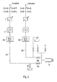
- each color changer is connected via a color pressure regulator 2, a metering pump 4 and a changeover valve 6A or 6B to a valve construction 8 serving as the first “pig station”, which is arranged at the input of a connecting line 12 leading to the application member 10.
- the application member 10 can be a rotary atomizer or, in particular, also a spray gun.
- a further controllable valve arrangement 14 serving as a second “pig station” is provided at the outlet of the connecting line 12.
- Lines for thinner (V) and compressed air (PL) are connected to the changeover valves 6A, 6B and to the valve arrangement 14 as shown via associated valves.
- drain lines RF are connected to the lines between the metering pumps 4 and the changeover valves 6A and 6B and to the valve construction 8, which discard the diluent used during rinsing processes.
- the first “pig station” or valve construction 8 can, for example to accommodate a displacer (not shown) serve according to the proposal of the beginning mentioned patent application 197 09 988.2 a ball of elastic deformable material, whose diameter in undeformed condition equal to or slightly larger than the inside diameter the connecting line 12 is.
- the valve construction 8 is (as also not shown in detail is) switchable between two positions such that the Displacer in the first position the way from Color changer A or B through the changeover valves 6A or 6B in the connecting line 12 releases while he at the second Position by directed into the valve construction 8 Pressure medium can be pressed into the connecting line 12.
- the valve construction 8 similar to that Diaphragm valve containing dead space-free construction Fig. 2 of the mentioned patent application 197 09 988.2 designed his.
- the valve arrangement 14 serving as the second pig station is also designed so that the pig in a valve position the path from the connecting line 12 into the application organ 10 releases and according to the invention in a different valve position is pushed back into the connecting line 12. Instead, it can be sufficient if the pig on the application organ 10 just hits against a stop and through the medium introduced under pressure in the valve arrangement 14, So thinner and / or compressed air can be pushed back into the line is.
- the coating material from a of the two color changers e.g. the color changer A coming through the changeover valve 6A, the valve construction 8, in the the pig in its resting position makes its way into the connecting line 12 releases, and through the valve assembly 14 to the application member 10 promoted.
- the newt or displacer in turn presses the rest of the line Coating material to the application member 10, while this Isolate material from the thinner until it becomes the second Pig station, that is to say reaches the valve arrangement 14, with which the Application process is finished.
- the valve arrangement 14 with which the Application process is finished.
- the switching position is also preferred of the main valve usually formed by the paint needle of the application process and by appropriate Signals reported.
- the pig is passed through the valve arrangement 14 Thinner liquid and / or compressed air back in the valve construction 8 conveyed.
- the thinner can drain the line RF connected to the valve construction 8.
- the color system between the concerned Color changer A or B and the associated switching valve 6A and 6B and the application member 10 rinsed be, the rinsing liquid from the paint system can flow through the line RF at the changeover valve.
- the new color material for a next coating cycle over the other color system from the color changer B to the application member 10 become.
- the one described could Setup even with a single color system without the switching valves 6A and 6B operate.
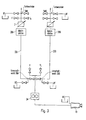
- FIG. 2 differs from that of Fig. 1 essentially in that between the first color changer A and the application member 10 after the color pressure regulator 2 and the dosing pump 4 first as a pig station serving valve construction 28A (corresponding to 8 in Fig. 1), a first connection line 22A and a first valve arrangement 24A (corresponding to 14 in Fig. 1) and between the second Color changer B and the application organ 10 a second as Valve construction 28B serving a pig station, a second Connection line 22B and a second valve assembly 24B are connected to the valve arrangements 24A, 24B lines for thinner and compressed air and on the connecting lines on or near the valve arrangements 24A, 24B drain lines RF connected.
- each of the two connection lines 22A, 22B will be the one therein coating material in the manner described each with its own valve design 28A and 28B positioned displacers to the application organ 10 pressed and from there the displacer moves back according to the invention, the two systems being self-sufficient, i.e. independent of each other can work.
- This facility has the particular advantage that when the pig is moved back in the connecting line 22A and while purging the associated system the other system connected to the color changer already be "preloaded” and with this system without delay the next coating process can be started.
- FIG. 3 Another advantageous variant of the device described is shown in Fig. 3.
- Fig. 1 there are two Color changers A, B optionally via changeover valves 36A or 36B can be coupled to the application member 10.
- Fig. 1 (and to Fig. 2) is only a single metering pump here 34 available, which are in the vicinity of the application member 10 between this and the switching valves 36A, 36B, while two compared to the distance between the application organ 10 and the switching valves 36A, 36B essential longer connecting lines 32A or 32B (corresponding to the Line 12 in Fig. 1) between the switching valves and the both color changers A and B run.
- the positioned in it Displacers are replaced by a sliding means pressurized thinner, compressed air, or instead can be any other print medium and the color changer supplied through the valve SMA or SMB as shown through the relevant connecting line 32A or 32B to the relevant changeover valve 36A or 36B pressed.
- the pig is switched off by the switch valves introduced flushing liquid and / or compressed air to its home position in valve construction 38A or 38B moved back.
- the system from the changeover valve to the color changer through the changeover valve introduced solvent are rinsed on Color changers can be discarded through a drain line RF can.
- the arrangement of the metering pump 34 between those to be pigged Connection lines 32A, 32B and the application member 10 is among others advantageous because only the newts here pure pressed towards the application organ Paint material must be dosed, which is better and more accurate is the dosing of the solvent with which Devices according to Fig. 1 and Fig. 2 the pig and thus the remaining color material to be applied must be promoted. At the same time, there is greater flexibility with regard to of the usable pusher for the pig. Moreover the effort is reduced since one of the two metering pumps 4 1 or FIG. 2 is saved.
- a displacer with which the remaining coating material to be applied by the Connecting line to the application organ is pressed
- a flowable one Use medium that is mixed with the coating material due to its nature and properties such as particularly high surface tension or more appropriate Avoids viscosity, and that by briefly opening a valve from a supply line between the blocked Coating material supply line and the connecting line is initiated before the material change valve assembly the connection from the material supply line for the coating material to be applied next opens.
- This also acts as a pig barrier or insulating medium can, for example, by a provided Valve can be introduced on the color changer or in a separate valve construction according to the pig station 1.
- This valve construction is switchable here between a first position in which one in the valve construction opening channel for the barrier or insulating medium closed by a valve and the way through the valve construction is approved for the coating material, and a second position in which said medium in the Connection line is pressed. It can be useful to open the valve so briefly or in pulses that the Medium introduced only in the form of a small liquid bubble becomes.
- Another possibility of modifying the exemplary embodiments described consists of the pig instead of rinsing liquid and / or compressed air through the after locking the Coating material supply line to be applied next Color material as a print medium through the connecting line to press.
- the cleaning effect of the newt can be sufficient so that no time-consuming rinsing of the Conducting and pressing the next color is required.
Landscapes
- Physics & Mathematics (AREA)
- Fluid Mechanics (AREA)
- Engineering & Computer Science (AREA)
- Mechanical Engineering (AREA)
- Spray Control Apparatus (AREA)
- Application Of Or Painting With Fluid Materials (AREA)
- Cleaning In General (AREA)
Description
Die Erfindung betrifft ein Verfahren gemäß dem Oberbegriff
des Anspruchs 1 und eine Einrichtung zum Durchführen eines
solchen Verfahrens.The invention relates to a method according to the preamble
of
Die Erfindung eignet sich besonders für Beschichtungsanlagen beispielsweise zur Serienbeschichtung von Kraftfahrzeugkarossen, in denen die verfügbaren Lackmaterialien unterschiedlicher Farbe üblicherweise in Ringleitungen zirkulieren, aus denen sie über eine als Farbwechsler dienende Ventilanordnung und eine Stichleitung zu dem Applikationsorgan gelangen, bei dem es sich z.B. um Rotationszerstäuber handeln kann oder auch um eine Sprühpistole, die mit dem Farbwechsler durch einen relativ langen Schlauch verbunden ist. Vor jedem Farbwechsel und auch vor längeren Betriebspausen muß bekanntlich die in der Stichleitung befindliche Farbe restlos entfernt werden.The invention is particularly suitable for coating systems for example for the series coating of motor vehicle bodies, in which the available paint materials are different Color usually circulate in ring lines which they have via a valve arrangement serving as a color changer and reach a branch line to the application organ, at which is e.g. can be rotary atomizers or also a spray gun that can be operated with the paint changer relatively long hose is connected. Before every color change and even before long breaks in operation must be known the color in the stub line is completely removed become.
Bisher wurde das in der Stichleitung befindliche Beschichtungsmaterial entweder verworfen oder wenigstens teilweise in die Ringleitung zurückgedrückt. Die Materialverluste beim Verwerfen sind in heutigen Anlagen in der Regel nicht mehr akzeptabel, besonders wenn es sich um relativ lange Stichleitungen handelt. Beim Zurückdrücken des Farbmaterials in das Materialzufuhrsystem besteht andererseits die Gefahr, daß z.B. aufgrund klemmender Farbventile oder Steuerungsfehler falsches Material in eine Ringleitung gelangt. Stattdessen ist es auch bekannt, schon vor Beendigung eines Lackiervorgangs die Verbindung zwischen der Ringleitung und der Stichleitung durch den Farbwechsler zu sperren und das restliche Beschichtungsmaterial aus der Stichleitung durch Spülflüssigkeit zu dem Applikationsorgan zu drücken, so daß es noch appliziert werden kann (US 4,348,425; EP 0 303 541 B1). Hierbei wird zwar das Problem des Zürückdrückens unerwünschten Materials in eine Ringleitung vermieden, doch kann sich das von der Spülflüssigkeit (Lösemittel) beaufschlagte restliche Beschichtungsmaterial zu einem großen Teil mit der Spülflüssigkeit vermischen. Insbesondere wurde festgestellt, daß das Lösemittel an der Kontaktstelle lanzenartig weit in die Mitte der Farblackfront eindringt. Der von diesem Lanzeneffekt beeinträchtigte Teil des Beschichtungsmaterials in der Stichleitung kann nicht appliziert werden, sondern muß verworfen werden, so daß sich beträchtliche Materialverluste ergeben.So far, the coating material in the stub was either discarded or at least partially in the ring line pushed back. The material losses in In today's systems, there are usually no longer any discards acceptable, especially if it is a relatively long stub is. When pushing the color material back into the Material supply system, on the other hand, there is a risk that e.g. due to jammed paint valves or control errors wrong material gets into a loop. Instead it is also known before a painting process is completed the connection between the ring line and the Block the branch line through the color changer and the rest Coating material from the stub by flushing liquid to push to the application organ so that it can still be applied (US 4,348,425; EP 0 303 541 B1). Here, the problem of pushing back becomes undesirable Avoided materials in a loop, but that can happen remaining of the rinsing liquid (solvent) Coating material to a large extent with the rinsing liquid mix. In particular, it was found that the solvent at the contact point is far into the lance Penetrates the middle of the colored lacquer front. The one with this lance effect impaired part of the coating material in the branch line cannot be applied, but must be discarded be, so that there is considerable loss of material.
Aus der US-A 5,221,047 ist es bei einer Beschichtungsanlage mit einer von einem Farbwechsler zu dem Applikationsorgan führenden Farbleitung bekannt, zum Farbwechsel vor der Beendigung des laufenden Beschichtungsvorgangs noch in der Farbleitung befindliches Farbmaterial mit einem Molch (slug) zum Zerstäuber zu drücken. Der Molch wird seinerseits durch Druckluft über Verdünnerflüssigkeit angetrieben und muß über eine zusätzliche Rückführleitung in die Molchstation zurückgefördert werden. Die Molchstation ist den Farbventilen innerhalb der Materialwechselventilanordnung vorgeschaltet. From US-A 5,221,047 it is in a coating system with one leading from a color changer to the application organ Color line known, for color change before termination of the ongoing coating process still in the paint line Color material with a pig (slug) to the atomizer to press. The newt in turn is compressed air driven by thinner liquid and must have an additional Return line fed back to the pig station become. The pig station is the color valves within the Material change valve arrangement upstream.
Hiervon ausgehend liegt der Erfindung die Aufgabe zugrunde, ein Verfahren und eine Einrichtung anzugeben, die beim Herausdrücken des Beschichtungsmaterials durch einen durch das Lösemittel oder sonstige Druckmedium beaufschlagten Molch aus der Verbindungsleitung in Richtung zum Applikationsorgan einfacher als bisher eine Vermischung von Beschichtungsmaterial und Druckmedium vermeidet.Proceeding from this, the object of the invention is to specify a method and a device that when pushing out of the coating material by a through the solvent or other pressure medium loaded pig from the connecting line in the direction to the application organ easier than before mixing coating material and avoids pressure medium.
Diese Aufgabe wird durch die Merkmale der unabhängigen Ansprüche gelöst.This object is achieved through the features of the independent claims solved.
Vorteilhafte Weiterbildungen der Erfindung sind in den Unteransprüchen gekennzeichnet.Advantageous developments of the invention are in the subclaims characterized.
Durch die Erfindung, wie bei der Beschichtungsanlage der US-A-5,221,047, wird erreicht, daß beispielsweise vor einem Farbwechsel oder einer Betriebspause oder einem aus sonstigen Gründen erforderlichen Spülvorgang das im laufenden Beschichtungszyklus verwendete Beschichtungsmaterial nahezu verlustfrei appliziert werden kann, ohne zuvor in das Ringleitungs- oder Materialzufuhrsystem zurückgedrückt werden zu müssen. Das Ergebnis ist eine beträchtliche Einsparung von Beschichtungsmaterial sowie die Möglichkeit, bei entsprechender Ausgestaltung der Einrichtung nach Beendigung eines Beschichtungszyklus nahezu verzögerungsfrei mit dem nächsten Zyklus beginnen zu können.The invention, as in the coating system of US-A-5,221,047, ensures that, for example, in front of a Color change or a business break or from another Rinsing process necessary for the ongoing Coating cycle used coating material almost can be applied losslessly without having previously Ring line or material supply system are pushed back to have to. The result is a substantial saving of Coating material as well as the possibility with appropriate Design of the facility after the completion of a coating cycle almost instantaneously with the next one Start cycle.
Zum Zurückdrücken des vor einem Farbwechsel oder einer Betriebspause im Verbindungsschlauch einer Sprühpistole verbleibenden Farblacks in das Ringleitungssystem wurde an sich in der DE-Patentanmeldung 197 09 988.2 vom 11.03.1997 schon vorgeschlagen, den Farblack mit einem Verdrängerkörper (Molch) in Form einer Kugel aus elastisch verformbaren Werkstoff zurückzudrücken, der zu diesem Zweck in einer geeigneten Ventilkonstruktion an der Sprühpistole positioniert ist und von dort durch Druckluft entgegen dem in der Ringleitung anstehenden Druck bis zu einem Anschlag in der Nähe des Farbwechlsers bewegt wird, von wo er anschließend durch Spülflüssigkeit und/ oder Druckluft zurück in die Ventilkonstruktion befördert wird. Das erläuterte Ziel der vorliegenden Erfindung ist hiermit nicht erreichbar.For pressing back before a color change or a break in operation remaining in the connecting hose of a spray gun Color varnish in the ring line system was in itself in DE patent application 197 09 988.2 dated March 11, 1997 suggested the colored paint with a displacer (Newt) in the form of a ball made of elastically deformable material push back for this purpose in a suitable Valve construction is positioned on the spray gun and from there by compressed air against that in the ring line pending pressure up to a stop near the color changer is moved from where it is subsequently washed with rinsing liquid and / or compressed air back into the valve construction is promoted. The explained object of the present invention cannot be reached with this.
An den in der Zeichnung dargestellten Ausführungsbeispielen wird die Erfindung Näher erläutert. Es zeigen:
- Fig. 1
- eine schematische und vereinfachte Darstellung einer Einrichtung zum Durchführen des hier beschriebenen Verfahrens;
- Fig. 2
- eine Einrichtung, die auf zwei dasselbe Applikationsorgan unabhängig voneinander speisende Systeme gemäß Fig. 1 erweitert ist;
- Fig. 3
- eine gegenüber Fig. 1 und Fig. 2 teilweise abgewandelte Einrichtung.
- Fig. 1
- a schematic and simplified representation of a device for performing the method described here;
- Fig. 2
- a device which is expanded to two systems feeding the same application organ independently of one another according to FIG. 1;
- Fig. 3
- a device which is partially modified compared to FIGS. 1 and 2.
Gemäß Fig. 1 sind zwei getrennte, als Materialwechselventilanordnung
dienende Farbwechsler A bzw. B an sich bekannter
und üblicher Art über Farbventile F, Fn z.B. an Ringleitungen
für entsprechend viele Lackfarben und über weitere Ventile V
und PL an Leitungen für Spülflüssigkeit (Verdünner) bzw. für
Druckluft angeschlossen. Jeder Farbwechsler ist ausgangsseitig
über je einen Farbdruckregler 2, eine Dosierpumpe 4 und
je ein Umschaltventil 6A bzw. 6B an eine als erste "Molchstation"
dienende Ventilkonstruktion 8 angeschlossen, die am
Eingang einer zu dem Applikationsorgan 10 führenden Verbindungsleitung
12 angeordnet ist. Das Applikationsorgan 10 kann
darstellungsgemäß ein Rotationszerstäuber oder insbesondere
auch eine Sprühpistole sein. Am Ausgang der Verbindungsleitung
12 ist eine als zweite "Molchstation" dienende weitere
steuerbare Ventilanordnung 14 vorgesehen. An die Umschaltventile
6A, 6B und an die Ventilanordnung 14 sind darstellungsgemäß
über zugehörige Ventile jeweils Leitungen für Verdünner
(V) und Druckluft (PL) angeschlossen. Ferner sind an die Leitungen
zwischen den Dosierpumpen 4 und den Umschaltventilen
6A bzw. 6B sowie an die Ventilkonstruktion 8 über je ein Ventil
Abflußleitungen RF angeschlossen, die bei Spülvorgängen
den verwendeten Verdünner verwerfen.According to FIG. 1, two separate color changers A and B, which serve as material change valve arrangements, are known and customary per se via color valves F, F n, for example on ring lines for a correspondingly large number of paint colors and via further valves V and PL on lines for rinsing liquid (thinner) or connected for compressed air. On the output side, each color changer is connected via a color pressure regulator 2, a metering pump 4 and a
Die erste "Molchstation" oder Ventilkonstruktion 8 kann beispielsweise
zur Aufnahme eines Verdrängerkörpers (nicht dargestellt)
dienen, der entsprechend dem Vorschlag der eingangs
erwähnten Patentanmeldung 197 09 988.2 eine Kugel aus elastisch
verformbaren Werkstoff sein kann, deren Durchmesser im
unverformten Zustand gleich oder etwas größer als der Innendurchmesser
der Verbindungsleitung 12 ist. Die Ventilkonstruktion
8 ist (wie ebenfalls nicht im einzelnen dargestellt
ist) zwischen zwei Stellungen derart umschaltbar, daß der
Verdrängerkörper bei der ersten Stellung den Weg von dem
Farbwechsler A oder B durch die Umschaltventile 6A oder 6B in
die Verbindungsleitung 12 freigibt, während er bei der zweiten
Stellung durch in die Ventilkonstruktion 8 geleitetes
Druckmedium in die Verbindungsleitung 12 drückbar ist. Beispielsweise
kann die Ventilkonstruktion 8 ähnlich der ein
Membranventil enthaltenden totraumfreien Konstruktion gemäß
Fig. 2 der erwähnten Patentanmeldung 197 09 988.2 gestaltet
sein.The first “pig station” or
Die als zweite Molchstation dienende Ventilanordnung 14 ist
ebenfalls so ausgebildet, daß der Molch in einer Ventilstellung
den Weg aus der Verbindungsleitung 12 in das Applikationsorgan
10 freigibt und erfindungsgemäß in einer anderen Ventilstellung
in die Verbindungsleitung 12 zurückgedrückt wird.
Stattdessen kann es aber genügen, wenn der Molch am Applikationsorgan
10 lediglich gegen einen Anschlag stößt und durch
das in der Ventilanordnung 14 unter Druck eingeleitete Medium,
also Verdünner und/oder Druckluft in die Leitung zurückdrückbar
ist.The
Im normalen Betrieb wird das Beschichtungsmaterial von einem
der beiden Farbwechsler, z.B. dem Farbwechsler A kommend
durch das Umschaltventil 6A, die Ventilkonstruktion 8, in der
der Molch in seiner Ruheposition den Weg in die Verbindungsleitung
12 freigibt, und durch die Ventilanordnung 14 zum Applikationsorgan
10 gefördert.In normal operation, the coating material from a
of the two color changers, e.g. the color changer A coming
through the
Zum Ende eines Beschichtungszyklus, nämlich sobald die üblicherweise
vorgesehene Programmsteuerung der Anlage errechnet
oder feststellt, daß zum Vollenden eines Beschichtungsvorgangs,
beispielsweise zur Fertiglackierung einer Karosse oder
eines bestimmten begrenzten Teils des Werkstücks gerade noch
soviel Beschichtungsmaterial benötigt wird, wie sich in der
Verbindungsleitung 12 zwischen den beiden Molchstationen befindet,
wird das bisher offene Farbventil F des betreffenden
Farbwechslers A geschlossen, dessen Verdünnerventil V geöffnet
und zugleich die Ventilkonstruktion 8 in die Stellung umgeschaltet,
in der der Molch oder Verdränger von dem nun anstelle
des Farbmaterials mit etwa demselben Druck mittels der
Dosierpumpe 4 zugeführten Verdünner in und durch die Verbindungsleitung
12 gedrückt wird. Der Molch bzw. Verdränger
drückt seinerseits das in der Leitung befindliche restliche
Beschichtungsmaterial zum Applikationsorgan 10, wobei er dieses
Material von dem Verdünner isoliert, bis er die zweite
Molchstation, also die Ventilanordnung 14 erreicht, womit der
Applikationsvorgang beendet ist. Sollte bei Beendigung des
Beschichtungsvorgangs der Molch nicht zeitgleich mit dem
Schließen des Hauptventils des Applikationsorgans 10 seine
Endposition in der Station 14 erreichen, also dort nicht oder
zu früh ankommen, so ist dafür zu sorgen, daß der Molch beim
nächsten Applikationsvorgang um eine entsprechende Zeitdifferenz
früher bzw. später gestartet wird. Dies kann als
"Selbstlern"-Vorgang der Programmsteuerung realisiert werden.
Beispielsweise wird beim ersten Applikationsvorgang der Molch
so spät gestartet, daß er die Station 14 voraussichtlich
nicht bis zum Schließen des Hauptventils erreicht. Dann wird
bei den nächsten Applikationsvorgängen der Startzeitpunkt
schrittweise jeweils um einen gegebenen Zeitbetrag früher
eingestellt. Dieser Vorgang wird so oft wiederholt, bis der
Molch schließlich zur richtigen Zeit in der Station 14 ankommt.
Die Ankunft des Molches in der Station wird durch ein
Signal gemeldet. Vorzugsweise wird auch die Schaltstellung
des in der Regel durch die Farbnadel gebildeten Hauptventils
des Applikationsvorgangs abgefragt und durch entsprechende
Signale gemeldet.At the end of a coating cycle, namely as soon as the usual
intended program control of the system is calculated
or finds that to complete a coating process,
for example to finish painting a body or
of a certain limited part of the workpiece
as much coating material is required as in the
Connecting
Sodann wird erfindungsgemäß der Molch durch in die Ventilanordnung 14 geleitete
Verdünnerflüssigkeit und/oder Druckluft wieder zurück in
die Ventilkonstruktion 8 befördert. Der Verdünner kann durch
die an die Ventilkonstruktion 8 angeschlossene Leitung RF abfließen.
Gleichzeitig können das Farbsystem zwischen dem betreffenden
Farbwechsler A oder B und dem zugehörigen Umschaltventil
6A bzw. 6B sowie das Applikationsorgan 10 gespült
werden, wobei die Spülflüssigkeit aus dem Farbsystem
über die Leitung RF am Umschaltventil abfließen kann.Then, according to the invention, the pig is passed through the
Sobald der Molch sich wieder in seiner Ruheposition in der
Ventilkonstruktion 8 befindet, kann das neue Farbmaterial für
einen nächsten Beschichtungszyklus über das andere Farbsystem
vom Farbwechsler B bis zum Applikationsorgan 10 angedrückt
werden. In einer vereinfachten Ausführungsform könnte die beschriebene
Einrichtung auch mit einem einzigen Farbsystem ohne
die Umschaltventile 6A und 6B arbeiten.As soon as the newt is in its resting position in the
Valve
Die Einrichtung nach Fig. 2 unterscheidet sich von der nach
Fig. 1 im wesentlichen dadurch, daß zwischen den ersten Farbwechsler
A und das Applikationsorgan 10 nach dem Farbdruckregler2
undderDosierpumpe4eineerste als Molchstation
dienende Ventilkonstruktion 28A (entsprechend 8 in Fig. 1),
eine erste Verbindungsleitung 22A und eine erste Ventilanordnung
24A (entsprechend 14 in Fig. 1) und zwischen den zweiten
Farbwechsler B und das Applikationsorgan 10 eine zweite als
Molchstation dienende Ventilkonstruktion 28B, eine zweite
Verbindungsleitung 22B und eine zweite Ventilanordnung 24B
geschaltet sind.Darstellungsgemäß sind an die Ventilanordnungen
24A, 24B Leitungen für Verdünner und Druckluft und an
die Verbindungsleitungen an den oder in der Nähe der Ventilanordnungen
24A, 24B Abflußleitungen RF angeschlossen. In
jeder der beiden Verbindungsleitungen 22A, 22B wird das darin
befindliche Beschichtungsmaterial in der beschriebenen Weise
durch je einen eigenen, in der betreffenden Ventilkonstruktion
28A bzw. 28B positionierten Verdrängerkörper zu dem Applikationsorgan
10 gedrückt und von dort der Verdrängerkörper erfindungsgemäß zuruckbewegt,
wobei die beiden Systeme autark, also unabhängig voneinander
arbeiten können. Diese Einrichtung hat den besonderen Vorteil,
daß beim Zurückbewegen des Molches in der Verbindungsleitung
22A und während des Spülens des zugehörigen Systems
das andere, an den Farbwechsler angeschlossene System
bereits "vorgeladen" sein und mit diesem System ohne Verzögerung
der nächste Beschichtungsvorgang begonnen werden kann.2 differs from that of
Fig. 1 essentially in that between the first color changer
A and the
Eine weitere vorteilhafte Variante der beschriebenen Einrichtung
ist in Fig. 3 dargestellt. Wie bei Fig. 1 sind zwei
Farbwechsler A, B wahlweise über Umschaltventile 36A bzw. 36B
mit dem Applikationsorgan 10 koppelbar. Im Gegensatz zu Fig.
1 (und zu Fig. 2) ist aber hier nur eine einzige Dosierpumpe
34 vorhanden, die sich in der Nähe des Applikationsorgans 10
zwischen diesem und den Umschaltventilen 36A, 36B befindet,
während zwei im Vergleich mit der Strecke zwischen dem Applikationsorgan
10 und den Umschaltventilen 36A, 36B wesentlich
längere Verbindungsleitungen 32A bzw. 32B (entsprechend der
Leitung 12 in Fig. 1) zwischen den Umschaltventilen und den
beiden Farbwechslern A bzw. B verlaufen. Am farbwechslerseitigen
Ende der beiden Verbindungsleitungen 32A, 32B ist je
eine als Molchstation dienende Ventilkonstruktion 38A bzw.
38B (entsprechend 8 in Fig. 1) vorgesehen. Die darin positionierten
Verdrängerkörper werden durch ein Schiebemittel, das
unter Druck zugeführter Verdünner, Druckluft oder stattdessen
ein beliebiges sonstiges Druckmedium sein kann und dem Farbwechsler
darstellungsgemäß durch das Ventil SMA bzw. SMB zugeführt
wird, durch die betreffende Verbindungsleitung 32A
bzw. 32B bis zu dem betreffenen Umschaltventil 36A bzw. 36B
gedrückt. Anschließend wird der Molch erfindungsgemäß von der bei den Umschaltventilen
eingeleiteten Spülflüssigkeit und/oder Druckluft
in seine Ausgangsposition in der Ventilkonstruktion 38A
bzw. 38B zurückbewegt. Bei dieser Einrichtung kann das System
vom Umschaltventil bis zum Farbwechsler durch das beim Umschaltventil
eingeleitete Lösemittel gespült werden, das am
Farbwechsler durch eine Abflußleitung RF verworfen werden
kann.Another advantageous variant of the device described
is shown in Fig. 3. As with Fig. 1, there are two
Color changers A, B optionally via
Die Anordnung der Dosierpumpe 34 zwischen den zu molchenden
Verbindungsleitungen 32A, 32B und dem Applikationsorgan 10
ist u.a. deshalb vorteilhaft, weil hier nur das von den Molchen
in Richtung zu dem Applikationsorgan gedrückte reine
Lackmaterial dosiert werden muß, was besser und genauer möglich
ist als das Dosieren des Lösemittels, mit dem bei den
Einrichtungen nach Fig. 1 und Fig. 2 der Molch und damit das
restliche zu applizierende Farbmaterial gefördert werden müssen.
Zugleich ergibt sich eine größere Flexibilität hinsichtlich
des verwendbaren Schiebemittels für den Molch. Außerdem
wird der Aufwand reduziert, da eine der beiden Dosierpumpen 4
gemäß Fig. 1 oder Fig. 2 eingespart wird.The arrangement of the
In Abwandlung der beschriebenen Ausführungsbeispiele der Erfindung
besteht die Möglichkeit, als Verdränger, mit dem das
restliche zu applizierende Beschichtungsmaterial durch die
Verbindungsleitung zu dem Applikationsorgan gedrückt wird,
anstelle eines kompakten Verdrängerkörpers ein fließfähiges
Medium zu verwenden, das die Vermischung mit dem Beschichtungsmaterial
aufgrund seiner Beschaffenheit und Eigenschaften
wie etwa besonders hoher Oberflächenspannung oder zweckmäßiger
Viskosität vermeidet, und das durch kurzzeitiges Öffnen
eines Ventils aus einer Zufuhrleitung zwischen der gesperrten
Beschichtungsmaterialzufuhrleitung und der Verbindungsleitung
eingeleitet wird, bevor die Materialwechselventilanordnung
die Verbindung von der Materialzufuhrleitung für
das als nächstes zu applizierende Beschichtungsmaterial öffnet.
Dieses ebenfalls wie ein Molch wirkende Sperr- oder Isoliermedium
kann beispielsweise durch ein hierfür vorgesehenes
Ventil am Farbwechsler eingeleitet werden oder auch in eine
gesonderte Ventilkonstruktion entsprechend der Molchstation
gemäß Fig. 1. Diese Ventilkonstruktion ist hier umschaltbar
zwischen einer ersten Stellung, in der ein in der Ventilkonstruktion
mündender Kanal für das Sperr- oder Isoliermedium
durch ein Ventil verschlossen und der Weg durch die Ventilkonstruktion
für das Beschichtungsmaterial freigegeben ist,
und einer zweiten Stellung, in der das genannte Medium in die
Verbindungsleitung gedrückt wird. Es kann zweckmäßig sein,
das Ventil so kurzfristig oder impulsartig zu öffnen, daß das
Medium nur in Form einer kleinen Flüssigkeitsblase eingeleitet
wird.In a modification of the described embodiments of the invention
there is the possibility, as a displacer, with which the
remaining coating material to be applied by the
Connecting line to the application organ is pressed,
instead of a compact displacer, a flowable one
Use medium that is mixed with the coating material
due to its nature and properties
such as particularly high surface tension or more appropriate
Avoids viscosity, and that by briefly opening
a valve from a supply line between the blocked
Coating material supply line and the connecting line
is initiated before the material change valve assembly
the connection from the material supply line for
the coating material to be applied next opens.
This also acts as a pig barrier or insulating medium
can, for example, by a provided
Valve can be introduced on the color changer or in a
separate valve construction according to the
Eine andere Möglichkeit der Abwandlung der beschriebenen Ausführungsbeispiele besteht darin, den Molch statt durch Spülflüssigkeit und/oder Druckluft durch das nach dem Sperren der Beschichtungsmaterialzufuhrleitung als nächstes zu applizierende Farbmaterial als Druckmedium durch die Verbindungsleitung zu drücken. Die Reinigungswirkung des Molches kann hierbei ausreichend sein, so daß kein zeitraubendes Spülen der Leitung und Andrücken der nächsten Farbe erforderlich ist.Another possibility of modifying the exemplary embodiments described consists of the pig instead of rinsing liquid and / or compressed air through the after locking the Coating material supply line to be applied next Color material as a print medium through the connecting line to press. The cleaning effect of the newt can be sufficient so that no time-consuming rinsing of the Conducting and pressing the next color is required.
Claims (16)
- Method of serially coating workpieces in which the coating material is supplied from a material supply conduit to a material changing valve arrangement (A, B) and from there through a connecting conduit (12) to an applicator (10), whereby before termination of the coating process the connection between the material supply conduit and the connecting conduit (12) is closed by the material changing valve arrangement (A, B), a valve (V) connected between a pressure medium supply conduit and the connecting conduit is opened and residual coating material remaining in the connecting conduit (12) is conveyed by the pressure of the pressure medium to the applicator (10) and applied by it, and whereby the remaining coating material to be applied is forced through the connecting conduit (12) to the applicator (10) by displacement means, which is acted on by the pressure medium and does not mix with the coating material, characterised in that after the application of the residual coating material in the connecting conduit (12), the displacement means is moved back through this connecting conduit (12) into its rest position at the end of the connecting conduit (12) remote from the applicator (10) by pressure medium supplied to its end remote from the applicator.
- A method as claimed in Claim 1, characterised in that a displacement body (slug) is used as the displacement means, which is acted on by the pressure medium.
- A method as claimed in Claim 2, characterised in that a ball of elastically deformable material is used as the displacement body, the diameter of which in the undeformed state is equal to or somewhat larger than the internal diameter of the connecting conduit (12).
- A method as claimed in Claim 1, characterised in that a flowable medium is used as the displacement means, which avoids mixing with the coating material as a result of its composition and characteristics and which is introduced by briefly opening a valve from a supply conduit between the closed coating material supply conduit and the connecting conduit before the material changing valve arrangement opens the connection from the material supply conduit for the next coating material to be applied.
- A method as claimed in one of Claims 1 to 4, characterised in that a flushing liquid supplied under pressure and/or compressed air is used as the pressure medium.
- A method as claimed in one of Claims 1 to 4, characterised in that the next coating material to be applied is used as the pressure medium after closing the coating material supply conduit.
- A method as claimed in one of Claims 1 to 6, characterised in that the time at which the connection between the coating material supply conduit and the connecting conduit (12) is closed and the forcing of the coating material remaining in the connecting conduit by the displacement means to the applicator (10) is commenced is so selected by a programmed controller that at this time approximately the amount of material required to complete the coating of the workpiece or a predetermined portion of the workpiece is still situated in the connecting conduit (12).
- A method as claimed in one of the preceding Claims, characterised in that a programmed controller determines whether the displacement means has not reached a predetermined end position (14) or has arrived there earlier, on termination of the coating process, whereby the arrival of the displacement means in the end position (14) is indicated and that, if required, the programmed controller starts the displacement body in a subsequent coating process earlier or later by an appropriate period of time.
- A method as claimed in one of the preceding Claims, characterised in that the termination of the coating process is defined by the time at which a main valve of the applicator (10) is closed.
- A method as claimed in one of Claims 1-3, characterised in that during the return movement of the displacement body through the connecting conduit (22A), coating material is supplied to the applicator (10) by a second connecting conduit (22B), which is also connected to a material supply system via a second material changing valve arrangement (B).
- Apparatus for serially coating workpieces including a material changing valve arrangement (A, B), connected between a material supply system and a connecting conduit (12) leading to an applicator (10), a valve construction (8) being provided, which may be switched between two positions and in which displacement means is arranged or introducable, which fits through the connecting conduit (12) and does not mix with the coating material as a result of its characteristics such that it opens the pathway in the connecting conduit (12) from the material changing valve arrangement (A, B), in the first position of the valve construction, (8) whilst it may be forced into the connecting conduit (12), in the second position, characterised in that the valve construction (8) is arranged between the material changing valve arrangement (A, B) and the connecting conduit (12) and the displacement means is moveable through the same connecting conduit (12) in the direction towards the applicator (10) and back to the valve construction (8).
- Apparatus as claimed in Claim 11, characterised in that a second connecting conduit (22B) is connected between the applicator (10) and a second material changing valve arrangement (B) connected to the material supply system, a second valve construction (28B) for receiving a second displacement means being provided between the second connecting conduit (22B) and the second material changing valve arrangement (B) and that the second displacement means is moveable back and forth between the second valve construction (28B) and a valve arrangement (24B), which is provided between the second connecting conduit (22B) and the applicator (10), independently of the displacement means in the other connecting conduit (22A).
- Apparatus as claimed in Claim 11, characterised in that the connecting conduit (12) is selectively connectable to one or other of two separate paint changing valve arrangements (A, B) via the valve construction (8) accommodating the displacement means and via a switch-over valve arrangement (6A, 6B).
- Apparatus as claimed in Claim 11, characterised in that connected upstream of the applicator (10) is a metering pump (34), connected upstream of the metering pump is a switch-over valve arrangement (36A, 36B) and connected to the switch-over valve arrangement on the side remote from the metering pump (34) are two connecting conduits (32A, 32B), which are selectively connectable to the applicator (10) and lead to a respective paint changing valve arrangement (A, B), with a respective valve construction (38A, 38B) serving to accommodate a displacement means.
- Apparatus as claimed in one of the Claims 11 to 14, characterised in that the displacement means is a ball of elastically deformable material, the diameter of which in the undeformed state is the same as or somewhat greater than the internal diameter of the connecting conduit (12).
- Apparatus as claimed in one of Claims 12 to 15, characterised in that the displacement means is acted on a further controllable valve arrangement (14; 24A, 24B; 36A, 36B), which is connected between the connecting conduit (12) and the applicator (10), by pressure medium supplied there in the direction back towards the switchable valve construction (8; 28A, 28B; 38A, 38B).
Applications Claiming Priority (2)
| Application Number | Priority Date | Filing Date | Title |
|---|---|---|---|
| DE19742588A DE19742588B4 (en) | 1997-09-26 | 1997-09-26 | Method for serial coating of workpieces |
| DE19742588 | 1997-09-26 |
Publications (2)
| Publication Number | Publication Date |
|---|---|
| EP0904848A1 EP0904848A1 (en) | 1999-03-31 |
| EP0904848B1 true EP0904848B1 (en) | 2003-04-09 |
Family
ID=7843756
Family Applications (1)
| Application Number | Title | Priority Date | Filing Date |
|---|---|---|---|
| EP98117999A Expired - Lifetime EP0904848B1 (en) | 1997-09-26 | 1998-09-23 | Method and apparatus for coating series of objects |
Country Status (3)
| Country | Link |
|---|---|
| EP (1) | EP0904848B1 (en) |
| DE (2) | DE19742588B4 (en) |
| ES (1) | ES2193455T3 (en) |
Cited By (2)
| Publication number | Priority date | Publication date | Assignee | Title |
|---|---|---|---|---|
| DE10239516A1 (en) * | 2002-08-28 | 2004-03-18 | Dürr Systems GmbH | Hose with pig for delivery of electrically conductive fluid paints or varnishes at high voltage comprises an inner layer enclosed in an insulating layer with high voltage resistance |
| EP3656476A4 (en) * | 2017-07-18 | 2021-04-21 | ABB Schweiz AB | PAINTING DEVICE |
Families Citing this family (45)
| Publication number | Priority date | Publication date | Assignee | Title |
|---|---|---|---|---|
| DE19805938A1 (en) * | 1998-02-13 | 1999-08-19 | Lactec Gmbh | Method and device for coating parts |
| DE19937474C2 (en) * | 1999-08-07 | 2001-08-02 | Eisenmann Lacktechnik Kg | Painting device with a gun unit, a color changing device and a piggable connecting device |
| DE19961271A1 (en) * | 1999-12-18 | 2001-07-05 | Duerr Systems Gmbh | Painting device |
| DE19962224A1 (en) * | 1999-12-22 | 2001-07-05 | Fraunhofer Ges Forschung | Coating system has unidirectional scraper equipment with scraper insertion station in coating material line with scraper magazine for storing a number of scrapers to be introduced |
| DE10064065B4 (en) * | 1999-12-22 | 2006-07-27 | Dürr Systems GmbH | Coating system for automated coating technology |
| DE10006310A1 (en) * | 2000-02-12 | 2001-08-16 | Lactec Gmbh | Coating method and apparatus |
| DE10033987A1 (en) * | 2000-07-13 | 2002-01-24 | Duerr Systems Gmbh | Process for supplying a coating member for the electrostatic series coating of workpieces and supply system therefor |
| DE10033986A1 (en) | 2000-07-13 | 2002-01-24 | Duerr Systems Gmbh | Process for using a pig in a coating installation and pig therefor |
| DE10063234C1 (en) * | 2000-12-19 | 2002-07-04 | Duerr Systems Gmbh | Hose system, for coating vehicle bodywork, has an inner hose with a moving pig through it held without kinks in an outer hose by compressed air in the ring zone between them |
| DE10115472A1 (en) | 2001-03-29 | 2002-10-10 | Duerr Systems Gmbh | Valve unit for use in electrostatic painting apparatus has an optoelectronic sensor device with light wave conductors and an optoelectronic sensor to sense an indexing position and to generate a corresponding sensing signal. |
| DE10115470A1 (en) | 2001-03-29 | 2002-10-10 | Duerr Systems Gmbh | Coating system with an atomizer change station |
| DE10115467A1 (en) | 2001-03-29 | 2002-10-02 | Duerr Systems Gmbh | Tool changing system for one machine |
| DE10115463A1 (en) * | 2001-03-29 | 2002-10-02 | Duerr Systems Gmbh | Atomizer for a coating system and process for its material supply |
| DE10120077B4 (en) * | 2001-04-24 | 2006-07-27 | Dürr Systems GmbH | Coating system for automated coating technology |
| DE10131562A1 (en) * | 2001-06-29 | 2003-01-16 | Duerr Systems Gmbh | Method and system for supplying a coating device |
| DE10145169A1 (en) | 2001-09-13 | 2003-04-03 | Duerr Systems Gmbh | Process for the serial coating of workpieces |
| DE10157966A1 (en) * | 2001-11-27 | 2003-06-05 | Duerr Systems Gmbh | Method and supply system for the metered supply of material to a coating device |
| DE10157938A1 (en) * | 2001-11-27 | 2003-06-05 | Duerr Systems Gmbh | Process for supplying paint to an atomizer and coating device |
| DE10160136B4 (en) * | 2001-12-07 | 2005-03-24 | Abb Patent Gmbh | Arrangement and method for the automatic cleaning of a pipeline system |
| DE10202711A1 (en) | 2002-01-24 | 2003-07-31 | Duerr Systems Gmbh | Sprayer unit for electrostatic serial coating of workpieces comprises an electrode array integrated into the ring section of insulating material on the outer housing of the unit |
| DE10211244A1 (en) * | 2002-03-13 | 2003-10-23 | Lactec Ges Fuer Moderne Lackte | Painting system for applying liquid coating material |
| DE10231421A1 (en) | 2002-07-11 | 2004-01-22 | Dürr Systems GmbH | Method and system for supplying a powder coating device |
| DE10233006B4 (en) | 2002-07-20 | 2007-07-05 | Eisenmann Lacktechnik Gmbh & Co. Kg | Method for supplying a paint application device with paint |
| DE10233198A1 (en) | 2002-07-22 | 2004-02-05 | Dürr Systems GmbH | rotary atomizers |
| DE10235102B4 (en) | 2002-08-01 | 2006-07-27 | Lac Tec GmbH Gesellschaft für moderne Lackiertechnik | Painting device with a piggable valve device |
| DE50309118D1 (en) | 2002-08-15 | 2008-03-20 | Duerr Systems Gmbh | Piggable hose for the electrostatic coating of workpieces |
| DE10239517A1 (en) | 2002-08-28 | 2004-03-11 | Dürr Systems GmbH | Coating device with a rotary atomizer and method for controlling its operation |
| DE10240072B4 (en) | 2002-08-30 | 2005-11-24 | Dürr Systems GmbH | Pig for conveying a coating material and process for its preparation |
| DE10240451A1 (en) | 2002-09-02 | 2004-03-11 | Dürr Systems GmbH | Sensor arrangement for a coating system |
| DE10245594A1 (en) | 2002-09-30 | 2004-04-08 | Dürr Systems GmbH | Collision detection method |
| US6991178B2 (en) | 2003-01-24 | 2006-01-31 | Dürr Systems, Inc. | Concentric paint atomizer shaping air rings |
| DE10335358A1 (en) * | 2003-08-01 | 2005-03-10 | Duerr Systems Gmbh | Coating agents changer |
| DE10346601A1 (en) * | 2003-10-07 | 2005-05-12 | Duerr Systems Gmbh | Method and system for supplying material consumers via pigging lines |
| FR2867702A1 (en) * | 2004-03-19 | 2005-09-23 | Haden Drysys Sa | DEVICE FOR RECOVERING A COATING PRODUCT CONTAINED IN A CANALIZATION |
| DE102004056789A1 (en) * | 2004-11-24 | 2006-06-01 | Eisenmann Maschinenbau Gmbh & Co. Kg | Electrical separation unit for a fluid delivery line |
| US8671495B2 (en) | 2006-11-06 | 2014-03-18 | Durr Systems, Inc. | Scraper pig |
| ATE485109T1 (en) | 2007-01-31 | 2010-11-15 | Abb As | VISCOUS LIQUID PIG FOR SEPARATING FLUIDS IN A PAINT LINE |
| DE102008015258B4 (en) * | 2008-03-20 | 2023-05-25 | Dürr Systems Ag | Color changer for a painting robot |
| DE102008037035B4 (en) * | 2008-08-08 | 2023-05-25 | Dürr Systems Ag | Valve arrangement of a painting robot |
| HUE025258T2 (en) | 2008-03-20 | 2016-02-29 | Duerr Systems Gmbh | Varnishing robots and associated operating procedures |
| US20120175432A1 (en) * | 2008-12-23 | 2012-07-12 | Abb Inc. | Paint shuttle system |
| DE102013007694A1 (en) * | 2013-05-03 | 2014-11-06 | Eisenmann Ag | Changing device for coating media and coating system for coating objects |
| FR3087361A1 (en) * | 2018-10-19 | 2020-04-24 | Exel Industries | METHOD OF SPRAYING A FLUID |
| DE102019103919A1 (en) * | 2019-02-15 | 2020-08-20 | Eisenmann Se | Coating system, device for the contactless determination of a state variable of a pig and a method for coating an object with a coating system |
| CN114130625B (en) * | 2021-11-08 | 2023-02-28 | 长飞光纤光缆股份有限公司 | Switching device for optical fiber coating material and using method thereof |
Citations (1)
| Publication number | Priority date | Publication date | Assignee | Title |
|---|---|---|---|---|
| DE19709988A1 (en) * | 1997-03-11 | 1998-10-01 | Inlac Ind Lackieranlagen Gmbh | Painting device |
Family Cites Families (10)
| Publication number | Priority date | Publication date | Assignee | Title |
|---|---|---|---|---|
| US3672570A (en) * | 1970-09-04 | 1972-06-27 | Nordson Corp | Sequence control of color change |
| US4375865A (en) * | 1980-08-12 | 1983-03-08 | Binks Manufacturing Company | Color change system for spray coating apparatus |
| US4348425A (en) * | 1981-01-26 | 1982-09-07 | Ransburg Corporation | Variable low-pressure fluid color change cycle |
| US4728033A (en) * | 1986-02-06 | 1988-03-01 | Trinity Industrial Corporation | Cleaning method upon color-change in an electrostatic multi-color coating apparatus |
| US4793016A (en) * | 1986-10-30 | 1988-12-27 | Valentine David E | Conduit cleaning apparatus |
| DE3865392D1 (en) * | 1987-08-14 | 1991-11-14 | Sames Sa | PAINT SPRAYER FOR COATING PRODUCTS, FOR EXAMPLE FOR WATER-SOLUBLE PAINT. |
| US5230842A (en) * | 1989-02-21 | 1993-07-27 | Munde Bruce A | Interior pipeline coating process |
| FR2662620A1 (en) * | 1990-05-31 | 1991-12-06 | Sames Sa | PROJECTION INSTALLATION OF PULVERIZED COATING PRODUCT WITH DEBIT CONTROL. |
| US5221047A (en) * | 1991-08-13 | 1993-06-22 | Gmfanuc Robotics Corporation | Method and system for cleaning a paint supply line and changing paint colors in production paint operations |
| DE4223054A1 (en) * | 1992-07-14 | 1994-01-20 | Gema Volstatic Ag St Gallen | Cleaning method for hoses, injectors etc. of powder coating equipment - involves driving one or more oversize sponge plugs through hose with axially aligned compressed air jet whose dia. is less than that of hose |
-
1997
- 1997-09-26 DE DE19742588A patent/DE19742588B4/en not_active Expired - Lifetime
-
1998
- 1998-09-23 DE DE59807823T patent/DE59807823D1/en not_active Expired - Lifetime
- 1998-09-23 ES ES98117999T patent/ES2193455T3/en not_active Expired - Lifetime
- 1998-09-23 EP EP98117999A patent/EP0904848B1/en not_active Expired - Lifetime
Patent Citations (1)
| Publication number | Priority date | Publication date | Assignee | Title |
|---|---|---|---|---|
| DE19709988A1 (en) * | 1997-03-11 | 1998-10-01 | Inlac Ind Lackieranlagen Gmbh | Painting device |
Cited By (3)
| Publication number | Priority date | Publication date | Assignee | Title |
|---|---|---|---|---|
| DE10239516A1 (en) * | 2002-08-28 | 2004-03-18 | Dürr Systems GmbH | Hose with pig for delivery of electrically conductive fluid paints or varnishes at high voltage comprises an inner layer enclosed in an insulating layer with high voltage resistance |
| EP3656476A4 (en) * | 2017-07-18 | 2021-04-21 | ABB Schweiz AB | PAINTING DEVICE |
| US11618048B2 (en) | 2017-07-18 | 2023-04-04 | Abb Schweiz Ag | Painting device |
Also Published As
| Publication number | Publication date |
|---|---|
| DE59807823D1 (en) | 2003-05-15 |
| EP0904848A1 (en) | 1999-03-31 |
| DE19742588B4 (en) | 2009-02-19 |
| ES2193455T3 (en) | 2003-11-01 |
| DE19742588A1 (en) | 1999-04-01 |
Similar Documents
| Publication | Publication Date | Title |
|---|---|---|
| EP0904848B1 (en) | Method and apparatus for coating series of objects | |
| DE69622407T2 (en) | LACQUERING ROBOT WITH A SYSTEM FOR LACQUER FEEDING | |
| EP3689473B1 (en) | Coating device and associated coating method | |
| EP1172152B1 (en) | Paint supply system with piggable supply lines for an electrostatic coating device | |
| DE2043789C3 (en) | Device for spraying paint on a series of objects | |
| EP0865830B2 (en) | Colour changer with reversible direction of paint flow | |
| DE19728155A1 (en) | Cleaning and preparation method for paint spray pipe | |
| DE3735816A1 (en) | Pump system for dispensing pressurised fluid | |
| EP1344572B1 (en) | Painting installation for coating pieces with a liquid material | |
| DE10131562A1 (en) | Method and system for supplying a coating device | |
| DE19951956A1 (en) | Valve assembly and method for flushing a color changer | |
| EP0541745B1 (en) | Spray coating device | |
| DE102016014948A1 (en) | Printhead and related operating procedures | |
| EP2269741B1 (en) | Piston metering apparatus for fluids and system for coating objects | |
| DE102008037035B4 (en) | Valve arrangement of a painting robot | |
| EP1314480B1 (en) | Method and device for paint supply in a coating device using a pig | |
| EP0104395A2 (en) | Paint mixing process and apparatus for carrying out this process | |
| EP3414017B1 (en) | Insulation device and coating system comprising said insulation device | |
| WO2024165408A1 (en) | Coating agent supply device and associated operating method | |
| EP1384518B1 (en) | Method and valve arrangement for controlling colour change in a coating installation | |
| EP2075073A1 (en) | Colour change system and method for changing colours | |
| DE4133840A1 (en) | Machine to coat articles with varying paint materials - has collection vessels, corresponding to number of paint changes, connected via valve block to return tube | |
| DE9106610U1 (en) | Spray coating device | |
| DE102008015494B4 (en) | Painting robot with a color changer | |
| DE3301911A1 (en) | Device for processing multi-component plastics |
Legal Events
| Date | Code | Title | Description |
|---|---|---|---|
| PUAI | Public reference made under article 153(3) epc to a published international application that has entered the european phase |
Free format text: ORIGINAL CODE: 0009012 |
|
| AK | Designated contracting states |
Kind code of ref document: A1 Designated state(s): DE ES FR GB IT |
|
| AX | Request for extension of the european patent |
Free format text: AL;LT;LV;MK;RO;SI |
|
| 17P | Request for examination filed |
Effective date: 19990910 |
|
| AKX | Designation fees paid |
Free format text: DE ES FR GB IT |
|
| 17Q | First examination report despatched |
Effective date: 20010613 |
|
| GRAH | Despatch of communication of intention to grant a patent |
Free format text: ORIGINAL CODE: EPIDOS IGRA |
|
| GRAH | Despatch of communication of intention to grant a patent |
Free format text: ORIGINAL CODE: EPIDOS IGRA |
|
| GRAA | (expected) grant |
Free format text: ORIGINAL CODE: 0009210 |
|
| AK | Designated contracting states |
Designated state(s): DE ES FR GB IT |
|
| REG | Reference to a national code |
Ref country code: GB Ref legal event code: FG4D Free format text: NOT ENGLISH |
|
| GBT | Gb: translation of ep patent filed (gb section 77(6)(a)/1977) |
Effective date: 20030409 |
|
| ET | Fr: translation filed | ||
| REG | Reference to a national code |
Ref country code: ES Ref legal event code: FG2A Ref document number: 2193455 Country of ref document: ES Kind code of ref document: T3 |
|
| PLBE | No opposition filed within time limit |
Free format text: ORIGINAL CODE: 0009261 |
|
| STAA | Information on the status of an ep patent application or granted ep patent |
Free format text: STATUS: NO OPPOSITION FILED WITHIN TIME LIMIT |
|
| 26N | No opposition filed |
Effective date: 20040112 |
|
| REG | Reference to a national code |
Ref country code: DE Ref legal event code: R082 Ref document number: 59807823 Country of ref document: DE Representative=s name: V. BEZOLD & PARTNER PATENTANWAELTE - PARTG MBB, DE Ref country code: DE Ref legal event code: R081 Ref document number: 59807823 Country of ref document: DE Owner name: DUERR SYSTEMS AG, DE Free format text: FORMER OWNER: DUERR SYSTEMS GMBH, 74321 BIETIGHEIM-BISSINGEN, DE |
|
| REG | Reference to a national code |
Ref country code: FR Ref legal event code: PLFP Year of fee payment: 19 |
|
| REG | Reference to a national code |
Ref country code: DE Ref legal event code: R082 Ref document number: 59807823 Country of ref document: DE Representative=s name: V. BEZOLD & PARTNER PATENTANWAELTE - PARTG MBB, DE Ref country code: DE Ref legal event code: R081 Ref document number: 59807823 Country of ref document: DE Owner name: DUERR SYSTEMS AG, DE Free format text: FORMER OWNER: DUERR SYSTEMS AG, 74321 BIETIGHEIM-BISSINGEN, DE |
|
| REG | Reference to a national code |
Ref country code: FR Ref legal event code: PLFP Year of fee payment: 20 |
|
| PGFP | Annual fee paid to national office [announced via postgrant information from national office to epo] |
Ref country code: GB Payment date: 20170921 Year of fee payment: 20 Ref country code: IT Payment date: 20170926 Year of fee payment: 20 Ref country code: DE Payment date: 20170928 Year of fee payment: 20 Ref country code: FR Payment date: 20170928 Year of fee payment: 20 |
|
| PGFP | Annual fee paid to national office [announced via postgrant information from national office to epo] |
Ref country code: ES Payment date: 20171025 Year of fee payment: 20 |
|
| REG | Reference to a national code |
Ref country code: DE Ref legal event code: R071 Ref document number: 59807823 Country of ref document: DE |
|
| REG | Reference to a national code |
Ref country code: GB Ref legal event code: PE20 Expiry date: 20180922 |
|
| PG25 | Lapsed in a contracting state [announced via postgrant information from national office to epo] |
Ref country code: GB Free format text: LAPSE BECAUSE OF EXPIRATION OF PROTECTION Effective date: 20180922 |
|
| REG | Reference to a national code |
Ref country code: ES Ref legal event code: FD2A Effective date: 20200904 |
|
| PG25 | Lapsed in a contracting state [announced via postgrant information from national office to epo] |
Ref country code: ES Free format text: LAPSE BECAUSE OF EXPIRATION OF PROTECTION Effective date: 20180924 |