EP0903481B1 - Abgasreiniger für direkteingespritzte verbrennungsmotoren - Google Patents
Abgasreiniger für direkteingespritzte verbrennungsmotoren Download PDFInfo
- Publication number
- EP0903481B1 EP0903481B1 EP98901578A EP98901578A EP0903481B1 EP 0903481 B1 EP0903481 B1 EP 0903481B1 EP 98901578 A EP98901578 A EP 98901578A EP 98901578 A EP98901578 A EP 98901578A EP 0903481 B1 EP0903481 B1 EP 0903481B1
- Authority
- EP
- European Patent Office
- Prior art keywords
- catalyst
- lean
- fuel injection
- sulfur component
- additional fuel
- Prior art date
- Legal status (The legal status is an assumption and is not a legal conclusion. Google has not performed a legal analysis and makes no representation as to the accuracy of the status listed.)
- Expired - Lifetime
Links
Images


Classifications
-
- F—MECHANICAL ENGINEERING; LIGHTING; HEATING; WEAPONS; BLASTING
- F01—MACHINES OR ENGINES IN GENERAL; ENGINE PLANTS IN GENERAL; STEAM ENGINES
- F01N—GAS-FLOW SILENCERS OR EXHAUST APPARATUS FOR MACHINES OR ENGINES IN GENERAL; GAS-FLOW SILENCERS OR EXHAUST APPARATUS FOR INTERNAL-COMBUSTION ENGINES
- F01N3/00—Exhaust or silencing apparatus having means for purifying, rendering innocuous, or otherwise treating exhaust
- F01N3/08—Exhaust or silencing apparatus having means for purifying, rendering innocuous, or otherwise treating exhaust for rendering innocuous
- F01N3/0807—Exhaust or silencing apparatus having means for purifying, rendering innocuous, or otherwise treating exhaust for rendering innocuous by using absorbents or adsorbents
- F01N3/0828—Exhaust or silencing apparatus having means for purifying, rendering innocuous, or otherwise treating exhaust for rendering innocuous by using absorbents or adsorbents characterised by the absorbed or adsorbed substances
- F01N3/0842—Nitrogen oxides
-
- F—MECHANICAL ENGINEERING; LIGHTING; HEATING; WEAPONS; BLASTING
- F01—MACHINES OR ENGINES IN GENERAL; ENGINE PLANTS IN GENERAL; STEAM ENGINES
- F01N—GAS-FLOW SILENCERS OR EXHAUST APPARATUS FOR MACHINES OR ENGINES IN GENERAL; GAS-FLOW SILENCERS OR EXHAUST APPARATUS FOR INTERNAL-COMBUSTION ENGINES
- F01N3/00—Exhaust or silencing apparatus having means for purifying, rendering innocuous, or otherwise treating exhaust
- F01N3/08—Exhaust or silencing apparatus having means for purifying, rendering innocuous, or otherwise treating exhaust for rendering innocuous
- F01N3/10—Exhaust or silencing apparatus having means for purifying, rendering innocuous, or otherwise treating exhaust for rendering innocuous by thermal or catalytic conversion of noxious components of exhaust
- F01N3/18—Exhaust or silencing apparatus having means for purifying, rendering innocuous, or otherwise treating exhaust for rendering innocuous by thermal or catalytic conversion of noxious components of exhaust characterised by methods of operation; Control
- F01N3/20—Exhaust or silencing apparatus having means for purifying, rendering innocuous, or otherwise treating exhaust for rendering innocuous by thermal or catalytic conversion of noxious components of exhaust characterised by methods of operation; Control specially adapted for catalytic conversion
-
- B—PERFORMING OPERATIONS; TRANSPORTING
- B01—PHYSICAL OR CHEMICAL PROCESSES OR APPARATUS IN GENERAL
- B01D—SEPARATION
- B01D53/00—Separation of gases or vapours; Recovering vapours of volatile solvents from gases; Chemical or biological purification of waste gases, e.g. engine exhaust gases, smoke, fumes, flue gases, aerosols
- B01D53/34—Chemical or biological purification of waste gases
- B01D53/92—Chemical or biological purification of waste gases of engine exhaust gases
- B01D53/94—Chemical or biological purification of waste gases of engine exhaust gases by catalytic processes
- B01D53/9495—Controlling the catalytic process
-
- F—MECHANICAL ENGINEERING; LIGHTING; HEATING; WEAPONS; BLASTING
- F02—COMBUSTION ENGINES; HOT-GAS OR COMBUSTION-PRODUCT ENGINE PLANTS
- F02D—CONTROLLING COMBUSTION ENGINES
- F02D41/00—Electrical control of supply of combustible mixture or its constituents
- F02D41/02—Circuit arrangements for generating control signals
- F02D41/021—Introducing corrections for particular conditions exterior to the engine
- F02D41/0235—Introducing corrections for particular conditions exterior to the engine in relation with the state of the exhaust gas treating apparatus
- F02D41/027—Introducing corrections for particular conditions exterior to the engine in relation with the state of the exhaust gas treating apparatus to purge or regenerate the exhaust gas treating apparatus
- F02D41/0275—Introducing corrections for particular conditions exterior to the engine in relation with the state of the exhaust gas treating apparatus to purge or regenerate the exhaust gas treating apparatus the exhaust gas treating apparatus being a NOx trap or adsorbent
- F02D41/028—Desulfurisation of NOx traps or adsorbent
-
- F—MECHANICAL ENGINEERING; LIGHTING; HEATING; WEAPONS; BLASTING
- F02—COMBUSTION ENGINES; HOT-GAS OR COMBUSTION-PRODUCT ENGINE PLANTS
- F02D—CONTROLLING COMBUSTION ENGINES
- F02D41/00—Electrical control of supply of combustible mixture or its constituents
- F02D41/30—Controlling fuel injection
- F02D41/38—Controlling fuel injection of the high pressure type
- F02D41/40—Controlling fuel injection of the high pressure type with means for controlling injection timing or duration
- F02D41/402—Multiple injections
- F02D41/405—Multiple injections with post injections
-
- F—MECHANICAL ENGINEERING; LIGHTING; HEATING; WEAPONS; BLASTING
- F01—MACHINES OR ENGINES IN GENERAL; ENGINE PLANTS IN GENERAL; STEAM ENGINES
- F01N—GAS-FLOW SILENCERS OR EXHAUST APPARATUS FOR MACHINES OR ENGINES IN GENERAL; GAS-FLOW SILENCERS OR EXHAUST APPARATUS FOR INTERNAL-COMBUSTION ENGINES
- F01N2570/00—Exhaust treating apparatus eliminating, absorbing or adsorbing specific elements or compounds
- F01N2570/04—Sulfur or sulfur oxides
-
- F—MECHANICAL ENGINEERING; LIGHTING; HEATING; WEAPONS; BLASTING
- F02—COMBUSTION ENGINES; HOT-GAS OR COMBUSTION-PRODUCT ENGINE PLANTS
- F02B—INTERNAL-COMBUSTION PISTON ENGINES; COMBUSTION ENGINES IN GENERAL
- F02B1/00—Engines characterised by fuel-air mixture compression
- F02B1/02—Engines characterised by fuel-air mixture compression with positive ignition
- F02B1/04—Engines characterised by fuel-air mixture compression with positive ignition with fuel-air mixture admission into cylinder
-
- F—MECHANICAL ENGINEERING; LIGHTING; HEATING; WEAPONS; BLASTING
- F02—COMBUSTION ENGINES; HOT-GAS OR COMBUSTION-PRODUCT ENGINE PLANTS
- F02D—CONTROLLING COMBUSTION ENGINES
- F02D2200/00—Input parameters for engine control
- F02D2200/02—Input parameters for engine control the parameters being related to the engine
- F02D2200/08—Exhaust gas treatment apparatus parameters
- F02D2200/0806—NOx storage amount, i.e. amount of NOx stored on NOx trap
-
- F—MECHANICAL ENGINEERING; LIGHTING; HEATING; WEAPONS; BLASTING
- F02—COMBUSTION ENGINES; HOT-GAS OR COMBUSTION-PRODUCT ENGINE PLANTS
- F02D—CONTROLLING COMBUSTION ENGINES
- F02D2200/00—Input parameters for engine control
- F02D2200/02—Input parameters for engine control the parameters being related to the engine
- F02D2200/08—Exhaust gas treatment apparatus parameters
- F02D2200/0818—SOx storage amount, e.g. for SOx trap or NOx trap
-
- F—MECHANICAL ENGINEERING; LIGHTING; HEATING; WEAPONS; BLASTING
- F02—COMBUSTION ENGINES; HOT-GAS OR COMBUSTION-PRODUCT ENGINE PLANTS
- F02D—CONTROLLING COMBUSTION ENGINES
- F02D41/00—Electrical control of supply of combustible mixture or its constituents
- F02D41/30—Controlling fuel injection
- F02D41/3011—Controlling fuel injection according to or using specific or several modes of combustion
- F02D41/3017—Controlling fuel injection according to or using specific or several modes of combustion characterised by the mode(s) being used
- F02D41/3023—Controlling fuel injection according to or using specific or several modes of combustion characterised by the mode(s) being used a mode being the stratified charge spark-ignited mode
-
- F—MECHANICAL ENGINEERING; LIGHTING; HEATING; WEAPONS; BLASTING
- F02—COMBUSTION ENGINES; HOT-GAS OR COMBUSTION-PRODUCT ENGINE PLANTS
- F02D—CONTROLLING COMBUSTION ENGINES
- F02D41/00—Electrical control of supply of combustible mixture or its constituents
- F02D41/30—Controlling fuel injection
- F02D41/38—Controlling fuel injection of the high pressure type
- F02D41/40—Controlling fuel injection of the high pressure type with means for controlling injection timing or duration
- F02D41/402—Multiple injections
-
- Y—GENERAL TAGGING OF NEW TECHNOLOGICAL DEVELOPMENTS; GENERAL TAGGING OF CROSS-SECTIONAL TECHNOLOGIES SPANNING OVER SEVERAL SECTIONS OF THE IPC; TECHNICAL SUBJECTS COVERED BY FORMER USPC CROSS-REFERENCE ART COLLECTIONS [XRACs] AND DIGESTS
- Y02—TECHNOLOGIES OR APPLICATIONS FOR MITIGATION OR ADAPTATION AGAINST CLIMATE CHANGE
- Y02T—CLIMATE CHANGE MITIGATION TECHNOLOGIES RELATED TO TRANSPORTATION
- Y02T10/00—Road transport of goods or passengers
- Y02T10/10—Internal combustion engine [ICE] based vehicles
- Y02T10/40—Engine management systems
Definitions
- the present invention relates to an exhaust purifying apparatus which performs exhaust purification in an in-cylinder injection type internal combustion engine that injects fuel directly into its combustion chamber, and particularly relates to an exhaust purifying apparatus for in an in-cylinder injection type internal combustion engine, suitable for use in the desorption of a sulfur component (SO x ) by fuel injection control.
- SO x sulfur component
- in-cylinder injection type internal combustion engines which inject fuel directly into the combustion chamber have been put to practical use.
- timing to inject fuel can be set freely, fuel injection is performed on a compression stroke in a low load operating area, a mixture with fuel concentration enough for ignition is collected locally near a spark plug, and super lean combustion by so-called stratified-charge combustion is performed, whereby an even further enhancement in fuel consumption is contrived.
- a lean NO x catalyst which can purify NO x even in an oxygen concentration excess condition in which oxygen in exhaust gases becomes excessive has been developed, and providing this NO x catalyst is indispensable.
- fuel or lubricating oil contains a sulfur component (S component), and a sulfur component such as this is also contained in exhaust gases.
- S component sulfur component
- NO x adheres and also a sulfur component such as this adheres.
- the sulfur component burns, and furthermore, it is oxidized on the lean NO x catalyst into SO 3 . And part of this SO 3 further reacts with an NO x occluding agent on the lean NO x catalyst and becomes a sulfate, so that it adheres to the lean NO x catalyst.
- a nitride and a sulfate adhere to the lean NO x catalyst, but, since the sulfate is higher in stability as a salt than the nitride and only a portion thereof is resolved even in a condition in which oxygen concentration has been reduced, the quantity of the sulfate remaining on the lean NO x catalyst increases with time. With this, as the NO x adhesion ability of the lean NO x catalyst is reduced with time, the catalytic performance of the lean NO x catalyst is degraded (this is referred to as S poisoning).
- the nitride which reduces the NO x adhesion ability of such a lean NO x catalyst has the resolve property if temperature becomes high.
- the opening angle of an idle speed control valve is increased to increase an intake air quantity and the engine revolution speed is raised to a high revolution region (2000 to 3000 rpm) and maintained, whereby an attempt is made to hold the catalyst bed temperature at high temperatures.
- the quantity of fuel is increased to make an air-fuel ratio rich, whereby an attempt is made to cause exhaust gases passing on a catalyst to be in a condition of deoxidization.
- JP-A-09 032 619 disclosed de-sulfatising a lean NO x -catalyst by an additional fuel injection during the exhaust or expansion stroke of an interval combustion engine. The additional fuel is burnt in the exhaust line.
- Figs. 1 through 7 show an exhaust purifying apparatus (exhaust emission control system) for an in-cylinder injection type internal combustion engine according to one embodiment of the present invention.
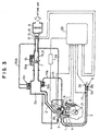
- ABS 50 is an air bypass valve (ABV), which is provided in a bypass path 50A communicating the intake passage 2 on the upstream side of the throttle valve 7 and the surging tank 2a together so as to bypass the installation portion of the throttle valve 7 of the intake passage 2.
- the ABV 50 adjusts an intake quantity separately from the throttle valve 7, thereby adjusting an air-fuel ratio.
- a water temperature sensor 19 for detecting an engine cooling water temperature is provided, and as shown in Fig. 2, a crank angle sensor (crank angle detection means) 21 for detecting a crank angle (this crank angle sensor 21 is also used as a revolution speed sensor for detecting an engine revolution speed) and a TDC sensor (cylinder identification sensor) 22 for detecting top dead center in the first cylinder (reference cylinder) are provided near cams, respectively.
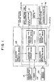
- ECU electronice control unit
- the hardware constitution of the ECU 23 is shown in Fig. 2, and this ECU 23 is provided with a central processing unit (CPU) 27 as its main portion.
- CPU central processing unit
- detection signals from the intake temperature sensor 12, atmospheric pressure sensor 13, throttle sensor 14, O 2 sensor 17, water temperature sensor 19, accelerator position sensor 24, catalytic temperature sensor 26, and from the battery sensor 25 are input through an input interface 28 and an analog/digital converter 30, and also detection signals from the air flow sensor 11, crank angle sensor 21, TDC sensor 22, idle switch 15, cranking switch 20, ignition switch, etc., are input through an input interface 29.
- the CPU 27 transmits and receives data through a bus line between itself and a ROM 31 for storing program data and fixed value data, a RAM 32 which is updated and overwritten in sequence, a free running counter 48, and a battery backup RAM (not shown) backed up by holding the stored contents while a battery is connected.
- fuel injection control signals are input to the solenoids (injector solenoids) 8a of the injectors 8 through injection drivers (fuel injection valve drive means) 34 of the cylinders (here, four cylinders).
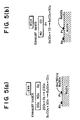
- this engine is provided, as modes of fuel injection, with a late injection mode (late lean operating mode) which performs fuel injection during a compression stroke (particularly, the second half of a compression stroke) in order to realize a lean operation by stratified super lean combustion and enhance fuel consumption, an early injection mode (early lean operating mode) which performs fuel injection during an intake stroke (particularly, the first half of an intake stroke) in order to realize a lean operation by pre-mixture combustion and obtain output by slow acceleration, a stoichiometric mode (stoichiometric operating mode) which performs fuel injection during an intake stroke in order to realize a stoichiometric operation (stoichiometric air-fuel ratio operation) by pre-mixture combustion and enhance output in comparison with the early injection mode, and an enriched mode (open loop mode) which realizes a rich operation (in which an air-fuel ratio is less than a stoichiometric air-fuel
- the desorbed NO 2 is deoxidized by unburned HC and CO in exhaust gases and is exhausted as N 2 .
- this lean NO x catalyst 9A in an oxygen concentration excess condition, O 2 adheres to the surface of platinum Pt, and the sulfur component, contained in fuel or a lubricating oil, is exhausted as SO 2 after combustion. SO 2 contained in the exhaust gases reacts with O 2 on the surface of platinum Pt and becomes SO 3 (2SO 2 + O 2 ⁇ 2SO 3 ). Then, part of the generated SO 3 couples with barium oxide BaO on the surface of platinum Pt, and a sulfate (BaSO 4 ) is generated and adheres to the lean NO x catalyst 9A.
- BaSO 4 barium oxide
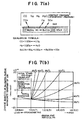
- the reason that the injection start time T INJ is thus set is for reliably burning the fuel injected by additional fuel injection (hereinafter also referred to as after-burning) and thereby raising exhaust gas temperature.
Landscapes
- Engineering & Computer Science (AREA)
- Chemical & Material Sciences (AREA)
- Combustion & Propulsion (AREA)
- General Engineering & Computer Science (AREA)
- Mechanical Engineering (AREA)
- Chemical Kinetics & Catalysis (AREA)
- Health & Medical Sciences (AREA)
- Biomedical Technology (AREA)
- Environmental & Geological Engineering (AREA)
- Analytical Chemistry (AREA)
- General Chemical & Material Sciences (AREA)
- Oil, Petroleum & Natural Gas (AREA)
- Toxicology (AREA)
- Exhaust Gas After Treatment (AREA)
- Electrical Control Of Air Or Fuel Supplied To Internal-Combustion Engine (AREA)
- Combined Controls Of Internal Combustion Engines (AREA)
- Combustion Methods Of Internal-Combustion Engines (AREA)
Claims (3)
- Abgasreinigungsvorrichtung einer Verbrennungskraftmaschine mit Zylindereinspritzung, die mit einem Kraftstoffeinspritzventil (8) für eine Einspritzung von Kraftstoff direkt in eine Verbrennungskammer versehen ist, und bei der Kraftstoff wenigstens während eines Kompressionshubs durch das Kraftstoffeinspritzventil (8) eingespritzt wird, um eine Schichtladeverbrennung durchzuführen, wobei die Abgasreinigungsvorrichtung für die Verbrennungskraftmaschine mit Zylindereinspritzung umfasst:einen NOx Katalysator (9A), der in einem Abgaskanal der Verbrennungskraftmaschine vorgesehen ist, wobei der NOx Katalysator bei einem Zustand mit einer überschüssigen Sauerstoffkonzentration NOx an sich selber adheriert und NOx in einem Zustand mit Sauerstoffkonzentrationsreduktion desorbiert, undeine Schwefelkomponenten-Desorptionseinrichtung (107) für eine Desorption einer Schwefelkomponente aus dem NOx Katalysator (9A),wobei die Schwefelkomponenten-Desorptionseinrichtung (107) während eines Expansionshubes zusätzlichen Kraftstoff zusätzlich zu der Haupteinspritzung für die Schichtladeverbrennung einspritzt und außerdem den zusätzlichen Kraftstoff wieder innerhalb der Verbrennungskammer verbrennt, so dass die Abgastemperatur auf eine vorher bestimmte Temperatur oder darüber hinaus erhöht wird, wodurch die Schwefelkomponente desorbiert wird.
- Abgasreinigungsvorrichtung für die Verbrennungskraftmaschine mit Zylindereinspritzung nach Anspruch 1, außerdem umfassend:eine Schwefelkomponenten-Adhäsionsmengen-Schätzeinrichtung (109) für eine Schätzung einer Adhäsionsmenge einer Schwefelkomponente, die an demNOx Katalysator (9A) adheriert und die NOx -Adhäsionsfähigkeit des NOx Katalysators (9A) reduziert,wobei die Schwefelkomponenten-Desorptionseinrichtung (107) einem Ausgang der Schwefelkomponenten-Adhäsionsmengen-Schätzeinrichtung (109) entsprechend betrieben wird.
- Abgasreinigungsvorrichtung für die Verbrennungskraftmaschine mit Zylindereinspritzung nach Anspruch 2, bei der die Schwefelkomponenten-Adhäsionsmengen-Schätzeinrichtung (109) eine Adhäsionsmenge der Schwefelkomponente auf der Basis einer Gesamtkraftstoffeinspritzmenge schätzt, die aus einem integrierten Wert von Injektor-Antriebszeitabschnitten aller Betriebsmodi erhalten wird.
Applications Claiming Priority (4)
| Application Number | Priority Date | Filing Date | Title |
|---|---|---|---|
| JP9098093A JP3067685B2 (ja) | 1997-03-31 | 1997-03-31 | 火花点火式筒内噴射型内燃機関の排気浄化装置 |
| JP9809397 | 1997-03-31 | ||
| JP98093/97 | 1997-03-31 | ||
| PCT/JP1998/000546 WO1998044245A1 (en) | 1997-03-31 | 1998-02-10 | Exhaust gas purifying device of cylinder injection internal combustion engine |
Publications (3)
| Publication Number | Publication Date |
|---|---|
| EP0903481A1 EP0903481A1 (de) | 1999-03-24 |
| EP0903481A4 EP0903481A4 (de) | 2000-06-21 |
| EP0903481B1 true EP0903481B1 (de) | 2003-09-03 |
Family
ID=14210738
Family Applications (1)
| Application Number | Title | Priority Date | Filing Date |
|---|---|---|---|
| EP98901578A Expired - Lifetime EP0903481B1 (de) | 1997-03-31 | 1998-02-10 | Abgasreiniger für direkteingespritzte verbrennungsmotoren |
Country Status (6)
| Country | Link |
|---|---|
| US (1) | US6173571B1 (de) |
| EP (1) | EP0903481B1 (de) |
| JP (1) | JP3067685B2 (de) |
| KR (1) | KR100318001B1 (de) |
| DE (1) | DE69817718T2 (de) |
| WO (1) | WO1998044245A1 (de) |
Families Citing this family (50)
| Publication number | Priority date | Publication date | Assignee | Title |
|---|---|---|---|---|
| JP3424557B2 (ja) * | 1997-08-06 | 2003-07-07 | マツダ株式会社 | エンジンの排気浄化装置 |
| JP3805098B2 (ja) * | 1998-03-26 | 2006-08-02 | 株式会社日立製作所 | エンジンの排気ガス浄化制御装置 |
| US6336320B1 (en) * | 1998-07-10 | 2002-01-08 | Toyota Jidosha Kabushiki Kaisha | Exhaust gas purification device for an internal combustion engine |
| US6289672B1 (en) * | 1998-07-21 | 2001-09-18 | Toyota Jidosha Kabushiki Kaisha | Exhaust gas purification device for an internal combustion engine |
| DE19852240A1 (de) * | 1998-11-12 | 2000-05-18 | Volkswagen Ag | Überwachungsverfahren für NOx-Speicherkatalysatoren und Abgasreinigungsvorrichtung zur Durchführung dieses Verfahrens |
| IT1304135B1 (it) * | 1998-11-26 | 2001-03-07 | Magneti Marelli Spa | Metodo di controllo dell' iniezione e dell' accensione in un motoreendotermico ad iniezione diretta per accelerare il riscaldamento del |
| JP3225957B2 (ja) | 1999-02-02 | 2001-11-05 | トヨタ自動車株式会社 | 内燃機関 |
| JP3680612B2 (ja) * | 1999-02-09 | 2005-08-10 | マツダ株式会社 | 筒内噴射式エンジンの制御装置 |
| JP2000282848A (ja) * | 1999-03-30 | 2000-10-10 | Nissan Motor Co Ltd | 内燃機関の排気浄化装置 |
| DE19920515C2 (de) * | 1999-05-05 | 2003-03-20 | Daimler Chrysler Ag | Abgasreinigungsanlage mit Stickoxidadsorber und Desulfatisierungsverfahren hierfür |
| DE60024713T2 (de) * | 1999-06-08 | 2006-09-28 | Honda Giken Kogyo K.K. | Abgasreinigungsvorrichtung und Regler für eine Brennkraftmaschine |
| DE19930086B4 (de) * | 1999-06-30 | 2004-08-19 | Robert Bosch Gmbh | Verfahren zum Betreiben einer Brennkraftmaschine |
| JP3304929B2 (ja) * | 1999-08-26 | 2002-07-22 | トヨタ自動車株式会社 | 内燃機関 |
| JP2001090594A (ja) * | 1999-09-22 | 2001-04-03 | Mazda Motor Corp | エンジンの制御装置 |
| JP3642273B2 (ja) * | 1999-10-21 | 2005-04-27 | 日産自動車株式会社 | 排気ガス浄化システム |
| DE19954549C2 (de) * | 1999-11-12 | 2001-12-20 | Daimler Chrysler Ag | Verfahren zum Betrieb einer Abgasreinigungsanlage mit Stickoxidadsorber und Beladungssensor |
| DE19959605A1 (de) * | 1999-12-10 | 2001-06-13 | Volkswagen Ag | Vorrichtung und Verfahren zur NOx- und/oder SOx-Regeneration eines NOx-Speicherkatalysators |
| JP3607980B2 (ja) * | 1999-12-16 | 2005-01-05 | トヨタ自動車株式会社 | 内燃機関 |
| US6928808B2 (en) * | 2000-02-17 | 2005-08-16 | Volkswagen Atkiengesellschaft | Device and method for controlling the nox regeneration of a nox storage catalyst |
| EP1201302B1 (de) | 2000-02-22 | 2007-08-08 | Mazda Motor Corporation | Katalysator zur abgasreinigung und verfahren zu seiner herstellung |
| JP2001241341A (ja) * | 2000-02-28 | 2001-09-07 | Hitachi Ltd | 内燃機関の排気ガス浄化装置及び浄化方法 |
| US6490855B1 (en) * | 2000-04-06 | 2002-12-10 | Ford Global Technologies, Inc. | Fueling control during emission control device purging |
| FR2812034B1 (fr) * | 2000-07-21 | 2003-03-21 | Renault | Procede d'injection de carburant |
| FR2812690B1 (fr) * | 2000-08-03 | 2003-04-04 | Peugeot Citroen Automobiles Sa | Systeme d'aide a la regeneration d'un catalyseur integre dans une ligne d'echappement d'un moteur de vehicule automobile |
| FR2812687B1 (fr) * | 2000-08-03 | 2003-04-04 | Peugeot Citroen Automobiles Sa | Systeme d'aide a la regeneration d'un catalyseur integre dans une ligne d'echappement d'un moteur de vehicule automobile |
| JP3546829B2 (ja) | 2000-10-04 | 2004-07-28 | トヨタ自動車株式会社 | 圧縮着火式内燃機関 |
| JP3981915B2 (ja) | 2001-04-03 | 2007-09-26 | 日産自動車株式会社 | 排気ガス浄化システム |
| JP2002364415A (ja) * | 2001-06-07 | 2002-12-18 | Mazda Motor Corp | エンジンの排気浄化装置 |
| US6490860B1 (en) * | 2001-06-19 | 2002-12-10 | Ford Global Technologies, Inc. | Open-loop method and system for controlling the storage and release cycles of an emission control device |
| US6591604B2 (en) * | 2001-06-19 | 2003-07-15 | Ford Global Technologies, Llc | Oxygen storage capacity estimation |
| US6536209B2 (en) * | 2001-06-26 | 2003-03-25 | Caterpillar Inc | Post injections during cold operation |
| JP2003090250A (ja) * | 2001-09-18 | 2003-03-28 | Nissan Motor Co Ltd | ディーゼルエンジンの制御装置 |
| DE10149236A1 (de) * | 2001-10-05 | 2003-04-30 | Bosch Gmbh Robert | Verfahren zum Betreiben einer Brennkraftmaschine insbesondere eines Kraftfahrzeugs |
| JP3885545B2 (ja) * | 2001-10-12 | 2007-02-21 | 日産自動車株式会社 | 内燃機関の排気浄化装置 |
| JP2003206785A (ja) * | 2002-01-18 | 2003-07-25 | Hitachi Ltd | エンジンの制御方法及び制御装置 |
| JP4114425B2 (ja) * | 2002-07-29 | 2008-07-09 | 三菱ふそうトラック・バス株式会社 | エンジン制御装置 |
| JP4135428B2 (ja) * | 2002-08-01 | 2008-08-20 | 日産自動車株式会社 | 内燃機関の排気浄化装置及び方法 |
| JP3925357B2 (ja) * | 2002-08-30 | 2007-06-06 | いすゞ自動車株式会社 | 排気ガス浄化システムの制御方法 |
| US6981370B2 (en) | 2002-12-03 | 2006-01-03 | Caterpillar Inc | Method and apparatus for PM filter regeneration |
| JP4385593B2 (ja) * | 2002-12-10 | 2009-12-16 | トヨタ自動車株式会社 | 内燃機関の排気浄化装置 |
| JP4357863B2 (ja) * | 2003-04-14 | 2009-11-04 | 株式会社デンソー | 多気筒内燃機関の気筒別空燃比算出装置 |
| JP2005048746A (ja) * | 2003-07-31 | 2005-02-24 | Nissan Motor Co Ltd | 内燃機関の燃焼制御装置 |
| JP4415648B2 (ja) * | 2003-11-05 | 2010-02-17 | いすゞ自動車株式会社 | サルファパージ制御方法及び排気ガス浄化システム |
| US7191591B2 (en) * | 2003-11-06 | 2007-03-20 | International Engine Intellectual Property Company, Llc | Attenuation of engine harshness during lean-to rich transitions |
| US7197867B2 (en) * | 2004-10-04 | 2007-04-03 | Southwest Research Institute | Method for the simultaneous desulfation of a lean NOx trap and regeneration of a Diesel particulate filter |
| US7117843B2 (en) * | 2004-10-07 | 2006-10-10 | International Engine Intellectual Property Company, Llc | Emission reduction in a diesel engine using an alternative combustion process and a low-pressure EGR loop |
| JP4100440B2 (ja) * | 2006-09-26 | 2008-06-11 | トヨタ自動車株式会社 | ハイブリッド車両の制御装置 |
| US8302380B2 (en) * | 2009-06-16 | 2012-11-06 | GM Global Technology Operations LLC | Desulfation systems and methods for lean NOx trap (LNT) |
| RU2460572C1 (ru) * | 2011-05-04 | 2012-09-10 | Государственное образовательное учреждение высшего профессионального образования "Самарский государственный университет путей сообщения" (СамГУПС) | Способ очистки газообразных продуктов сгорания |
| CN112065540B (zh) * | 2020-09-09 | 2021-09-21 | 安徽江淮汽车集团股份有限公司 | 一种nsc的脱硫方法 |
Family Cites Families (23)
| Publication number | Priority date | Publication date | Assignee | Title |
|---|---|---|---|---|
| JPS63150441A (ja) | 1986-12-15 | 1988-06-23 | Toyota Motor Corp | 触媒付着硫黄化合物除去方法 |
| JP2748686B2 (ja) | 1990-11-16 | 1998-05-13 | トヨタ自動車株式会社 | 筒内直接噴射式火花点火機関 |
| JP2605586B2 (ja) * | 1992-07-24 | 1997-04-30 | トヨタ自動車株式会社 | 内燃機関の排気浄化装置 |
| JP2605553B2 (ja) * | 1992-08-04 | 1997-04-30 | トヨタ自動車株式会社 | 内燃機関の排気浄化装置 |
| JP2745985B2 (ja) | 1992-08-13 | 1998-04-28 | トヨタ自動車株式会社 | 内燃機関の排気浄化装置 |
| DE69420488T2 (de) * | 1993-01-19 | 2000-04-13 | Toyota Jidosha K.K., Toyota | Abgasreinigungsgerät für eine brennkraftmaschine |
| EP0621400B1 (de) * | 1993-04-23 | 1999-03-31 | Daimler-Benz Aktiengesellschaft | Luftverdichtende Einspritzbrennkraftmaschine mit einer Abgasnachbehandlungseinrichtung zur Reduzierung von Stickoxiden |
| JP3404846B2 (ja) | 1993-12-28 | 2003-05-12 | トヨタ自動車株式会社 | 自動変速機付内燃機関の制御装置 |
| JP3412314B2 (ja) | 1995-02-13 | 2003-06-03 | トヨタ自動車株式会社 | 内燃機関の排気浄化装置 |
| JP3334396B2 (ja) | 1995-01-20 | 2002-10-15 | トヨタ自動車株式会社 | 内燃機関の排気浄化装置 |
| JP3574203B2 (ja) | 1994-04-12 | 2004-10-06 | トヨタ自動車株式会社 | 内燃機関の排気浄化方法 |
| JPH08105318A (ja) | 1994-10-05 | 1996-04-23 | Mitsubishi Motors Corp | 排気浄化触媒を備えた内燃エンジン |
| JP3030412B2 (ja) | 1994-06-17 | 2000-04-10 | 三菱自動車工業株式会社 | 内燃エンジンの排気浄化触媒装置 |
| DE19536098C2 (de) | 1994-09-29 | 1997-09-18 | Fuji Heavy Ind Ltd | System und Verfahren zur Steuerung der Katalysatoraktivierung in einem Motor mit Kraftstoffdirekteinspritzung |
| JPH08100638A (ja) | 1994-09-29 | 1996-04-16 | Fuji Heavy Ind Ltd | 筒内噴射エンジンの触媒活性化制御装置 |
| KR0185697B1 (ko) | 1995-01-20 | 1999-03-20 | 와다 아키히로 | 내연기관의 배기정화방법 |
| JP3052777B2 (ja) | 1995-04-27 | 2000-06-19 | 三菱自動車工業株式会社 | 筒内噴射型内燃機関 |
| JP3671455B2 (ja) | 1995-04-28 | 2005-07-13 | 株式会社デンソー | 内燃機関の排気浄化装置 |
| JP3757433B2 (ja) | 1995-05-18 | 2006-03-22 | 三菱自動車工業株式会社 | エンジンの排気ガス浄化装置 |
| JP3870430B2 (ja) * | 1995-07-14 | 2007-01-17 | 三菱自動車工業株式会社 | 筒内噴射型内燃機関 |
| US5704339A (en) * | 1996-04-26 | 1998-01-06 | Ford Global Technologies, Inc. | method and apparatus for improving vehicle fuel economy |
| US5839275A (en) * | 1996-08-20 | 1998-11-24 | Toyota Jidosha Kabushiki Kaisha | Fuel injection control device for a direct injection type engine |
| US5910096A (en) * | 1997-12-22 | 1999-06-08 | Ford Global Technologies, Inc. | Temperature control system for emission device coupled to direct injection engines |
-
1997
- 1997-03-31 JP JP9098093A patent/JP3067685B2/ja not_active Expired - Lifetime
-
1998
- 1998-02-10 WO PCT/JP1998/000546 patent/WO1998044245A1/ja not_active Ceased
- 1998-02-10 EP EP98901578A patent/EP0903481B1/de not_active Expired - Lifetime
- 1998-02-10 DE DE69817718T patent/DE69817718T2/de not_active Expired - Lifetime
- 1998-02-10 KR KR1019980709742A patent/KR100318001B1/ko not_active Expired - Fee Related
- 1998-02-10 US US09/180,448 patent/US6173571B1/en not_active Expired - Lifetime
Also Published As
| Publication number | Publication date |
|---|---|
| JPH10274031A (ja) | 1998-10-13 |
| EP0903481A4 (de) | 2000-06-21 |
| DE69817718D1 (de) | 2003-10-09 |
| DE69817718T2 (de) | 2004-07-15 |
| EP0903481A1 (de) | 1999-03-24 |
| JP3067685B2 (ja) | 2000-07-17 |
| KR20000016174A (ko) | 2000-03-25 |
| KR100318001B1 (ko) | 2002-04-17 |
| US6173571B1 (en) | 2001-01-16 |
| WO1998044245A1 (en) | 1998-10-08 |
Similar Documents
| Publication | Publication Date | Title |
|---|---|---|
| EP0903481B1 (de) | Abgasreiniger für direkteingespritzte verbrennungsmotoren | |
| US7111452B2 (en) | Control device of hydrogen engine | |
| US7127883B1 (en) | Exhaust gas purifying apparatus of internal combustion engine | |
| JP3702924B2 (ja) | 排気浄化装置 | |
| EP1148215A1 (de) | Abgasreiniger für brennkraftmaschinen | |
| EP0908613A2 (de) | Abgassteuerungssystem für Brennkraftmaschine mit NOx-Katalysator | |
| US20020129600A1 (en) | Cylinder injection type internal combustion engine | |
| JP3870430B2 (ja) | 筒内噴射型内燃機関 | |
| JP3460503B2 (ja) | 筒内噴射型内燃機関の排気浄化装置 | |
| JPH08105318A (ja) | 排気浄化触媒を備えた内燃エンジン | |
| US10933374B2 (en) | Exhaust emission control device, method and computer program product for an engine | |
| JP3085192B2 (ja) | エンジンの排気ガス浄化装置 | |
| JP3873537B2 (ja) | 内燃機関の排気浄化装置 | |
| JP4161429B2 (ja) | 希薄燃焼内燃機関 | |
| JP2001020781A (ja) | 内燃機関の排気浄化装置 | |
| JP4345202B2 (ja) | 内燃機関の排気浄化装置 | |
| JP4134395B2 (ja) | 筒内噴射型内燃機関 | |
| JPH11229864A (ja) | 内燃機関の排気浄化装置 | |
| JP3867182B2 (ja) | 内燃機関 | |
| JP2004360569A (ja) | 内燃機関の排気浄化制御装置 | |
| JP2000161045A (ja) | 内燃機関の排気浄化装置 | |
| JP3835071B2 (ja) | 内燃機関の排気浄化装置 | |
| JP2003041968A (ja) | 内燃機関の制御装置 | |
| JP2004232555A (ja) | 内燃機関の排気浄化システム | |
| JP4457442B2 (ja) | 内燃機関の排気浄化装置 |
Legal Events
| Date | Code | Title | Description |
|---|---|---|---|
| PUAI | Public reference made under article 153(3) epc to a published international application that has entered the european phase |
Free format text: ORIGINAL CODE: 0009012 |
|
| 17P | Request for examination filed |
Effective date: 19981110 |
|
| AK | Designated contracting states |
Kind code of ref document: A1 Designated state(s): DE FR GB |
|
| A4 | Supplementary search report drawn up and despatched |
Effective date: 20000510 |
|
| AK | Designated contracting states |
Kind code of ref document: A4 Designated state(s): DE FR GB |
|
| RIC1 | Information provided on ipc code assigned before grant |
Free format text: 7F 02D 41/02 A, 7B 01D 53/94 B, 7F 01N 3/08 B |
|
| GRAH | Despatch of communication of intention to grant a patent |
Free format text: ORIGINAL CODE: EPIDOS IGRA |
|
| GRAS | Grant fee paid |
Free format text: ORIGINAL CODE: EPIDOSNIGR3 |
|
| GRAA | (expected) grant |
Free format text: ORIGINAL CODE: 0009210 |
|
| AK | Designated contracting states |
Kind code of ref document: B1 Designated state(s): DE FR GB |
|
| REG | Reference to a national code |
Ref country code: GB Ref legal event code: FG4D |
|
| REF | Corresponds to: |
Ref document number: 69817718 Country of ref document: DE Date of ref document: 20031009 Kind code of ref document: P |
|
| ET | Fr: translation filed | ||
| PLBE | No opposition filed within time limit |
Free format text: ORIGINAL CODE: 0009261 |
|
| STAA | Information on the status of an ep patent application or granted ep patent |
Free format text: STATUS: NO OPPOSITION FILED WITHIN TIME LIMIT |
|
| 26N | No opposition filed |
Effective date: 20040604 |
|
| REG | Reference to a national code |
Ref country code: FR Ref legal event code: CA |
|
| REG | Reference to a national code |
Ref country code: FR Ref legal event code: PLFP Year of fee payment: 19 |
|
| REG | Reference to a national code |
Ref country code: FR Ref legal event code: PLFP Year of fee payment: 20 |
|
| PGFP | Annual fee paid to national office [announced via postgrant information from national office to epo] |
Ref country code: FR Payment date: 20170112 Year of fee payment: 20 Ref country code: DE Payment date: 20170207 Year of fee payment: 20 |
|
| PGFP | Annual fee paid to national office [announced via postgrant information from national office to epo] |
Ref country code: GB Payment date: 20170208 Year of fee payment: 20 |
|
| REG | Reference to a national code |
Ref country code: DE Ref legal event code: R071 Ref document number: 69817718 Country of ref document: DE |
|
| REG | Reference to a national code |
Ref country code: GB Ref legal event code: PE20 Expiry date: 20180209 |
|
| PG25 | Lapsed in a contracting state [announced via postgrant information from national office to epo] |
Ref country code: GB Free format text: LAPSE BECAUSE OF EXPIRATION OF PROTECTION Effective date: 20180209 |