EP0903481B1 - Exhaust gas purifying device of cylinder injection internal combustion engine - Google Patents
Exhaust gas purifying device of cylinder injection internal combustion engine Download PDFInfo
- Publication number
- EP0903481B1 EP0903481B1 EP98901578A EP98901578A EP0903481B1 EP 0903481 B1 EP0903481 B1 EP 0903481B1 EP 98901578 A EP98901578 A EP 98901578A EP 98901578 A EP98901578 A EP 98901578A EP 0903481 B1 EP0903481 B1 EP 0903481B1
- Authority
- EP
- European Patent Office
- Prior art keywords
- catalyst
- lean
- fuel injection
- sulfur component
- additional fuel
- Prior art date
- Legal status (The legal status is an assumption and is not a legal conclusion. Google has not performed a legal analysis and makes no representation as to the accuracy of the status listed.)
- Expired - Lifetime
Links
Images


Classifications
-
- F—MECHANICAL ENGINEERING; LIGHTING; HEATING; WEAPONS; BLASTING
- F01—MACHINES OR ENGINES IN GENERAL; ENGINE PLANTS IN GENERAL; STEAM ENGINES
- F01N—GAS-FLOW SILENCERS OR EXHAUST APPARATUS FOR MACHINES OR ENGINES IN GENERAL; GAS-FLOW SILENCERS OR EXHAUST APPARATUS FOR INTERNAL COMBUSTION ENGINES
- F01N3/00—Exhaust or silencing apparatus having means for purifying, rendering innocuous, or otherwise treating exhaust
- F01N3/08—Exhaust or silencing apparatus having means for purifying, rendering innocuous, or otherwise treating exhaust for rendering innocuous
- F01N3/0807—Exhaust or silencing apparatus having means for purifying, rendering innocuous, or otherwise treating exhaust for rendering innocuous by using absorbents or adsorbents
- F01N3/0828—Exhaust or silencing apparatus having means for purifying, rendering innocuous, or otherwise treating exhaust for rendering innocuous by using absorbents or adsorbents characterised by the absorbed or adsorbed substances
- F01N3/0842—Nitrogen oxides
-
- F—MECHANICAL ENGINEERING; LIGHTING; HEATING; WEAPONS; BLASTING
- F01—MACHINES OR ENGINES IN GENERAL; ENGINE PLANTS IN GENERAL; STEAM ENGINES
- F01N—GAS-FLOW SILENCERS OR EXHAUST APPARATUS FOR MACHINES OR ENGINES IN GENERAL; GAS-FLOW SILENCERS OR EXHAUST APPARATUS FOR INTERNAL COMBUSTION ENGINES
- F01N3/00—Exhaust or silencing apparatus having means for purifying, rendering innocuous, or otherwise treating exhaust
- F01N3/08—Exhaust or silencing apparatus having means for purifying, rendering innocuous, or otherwise treating exhaust for rendering innocuous
- F01N3/10—Exhaust or silencing apparatus having means for purifying, rendering innocuous, or otherwise treating exhaust for rendering innocuous by thermal or catalytic conversion of noxious components of exhaust
- F01N3/18—Exhaust or silencing apparatus having means for purifying, rendering innocuous, or otherwise treating exhaust for rendering innocuous by thermal or catalytic conversion of noxious components of exhaust characterised by methods of operation; Control
- F01N3/20—Exhaust or silencing apparatus having means for purifying, rendering innocuous, or otherwise treating exhaust for rendering innocuous by thermal or catalytic conversion of noxious components of exhaust characterised by methods of operation; Control specially adapted for catalytic conversion ; Methods of operation or control of catalytic converters
-
- B—PERFORMING OPERATIONS; TRANSPORTING
- B01—PHYSICAL OR CHEMICAL PROCESSES OR APPARATUS IN GENERAL
- B01D—SEPARATION
- B01D53/00—Separation of gases or vapours; Recovering vapours of volatile solvents from gases; Chemical or biological purification of waste gases, e.g. engine exhaust gases, smoke, fumes, flue gases, aerosols
- B01D53/34—Chemical or biological purification of waste gases
- B01D53/92—Chemical or biological purification of waste gases of engine exhaust gases
- B01D53/94—Chemical or biological purification of waste gases of engine exhaust gases by catalytic processes
- B01D53/9495—Controlling the catalytic process
-
- F—MECHANICAL ENGINEERING; LIGHTING; HEATING; WEAPONS; BLASTING
- F02—COMBUSTION ENGINES; HOT-GAS OR COMBUSTION-PRODUCT ENGINE PLANTS
- F02D—CONTROLLING COMBUSTION ENGINES
- F02D41/00—Electrical control of supply of combustible mixture or its constituents
- F02D41/02—Circuit arrangements for generating control signals
- F02D41/021—Introducing corrections for particular conditions exterior to the engine
- F02D41/0235—Introducing corrections for particular conditions exterior to the engine in relation with the state of the exhaust gas treating apparatus
- F02D41/027—Introducing corrections for particular conditions exterior to the engine in relation with the state of the exhaust gas treating apparatus to purge or regenerate the exhaust gas treating apparatus
- F02D41/0275—Introducing corrections for particular conditions exterior to the engine in relation with the state of the exhaust gas treating apparatus to purge or regenerate the exhaust gas treating apparatus the exhaust gas treating apparatus being a NOx trap or adsorbent
- F02D41/028—Desulfurisation of NOx traps or adsorbent
-
- F—MECHANICAL ENGINEERING; LIGHTING; HEATING; WEAPONS; BLASTING
- F02—COMBUSTION ENGINES; HOT-GAS OR COMBUSTION-PRODUCT ENGINE PLANTS
- F02D—CONTROLLING COMBUSTION ENGINES
- F02D41/00—Electrical control of supply of combustible mixture or its constituents
- F02D41/30—Controlling fuel injection
- F02D41/38—Controlling fuel injection of the high pressure type
- F02D41/40—Controlling fuel injection of the high pressure type with means for controlling injection timing or duration
- F02D41/402—Multiple injections
- F02D41/405—Multiple injections with post injections
-
- F—MECHANICAL ENGINEERING; LIGHTING; HEATING; WEAPONS; BLASTING
- F01—MACHINES OR ENGINES IN GENERAL; ENGINE PLANTS IN GENERAL; STEAM ENGINES
- F01N—GAS-FLOW SILENCERS OR EXHAUST APPARATUS FOR MACHINES OR ENGINES IN GENERAL; GAS-FLOW SILENCERS OR EXHAUST APPARATUS FOR INTERNAL COMBUSTION ENGINES
- F01N2570/00—Exhaust treating apparatus eliminating, absorbing or adsorbing specific elements or compounds
- F01N2570/04—Sulfur or sulfur oxides
-
- F—MECHANICAL ENGINEERING; LIGHTING; HEATING; WEAPONS; BLASTING
- F02—COMBUSTION ENGINES; HOT-GAS OR COMBUSTION-PRODUCT ENGINE PLANTS
- F02B—INTERNAL-COMBUSTION PISTON ENGINES; COMBUSTION ENGINES IN GENERAL
- F02B1/00—Engines characterised by fuel-air mixture compression
- F02B1/02—Engines characterised by fuel-air mixture compression with positive ignition
- F02B1/04—Engines characterised by fuel-air mixture compression with positive ignition with fuel-air mixture admission into cylinder
-
- F—MECHANICAL ENGINEERING; LIGHTING; HEATING; WEAPONS; BLASTING
- F02—COMBUSTION ENGINES; HOT-GAS OR COMBUSTION-PRODUCT ENGINE PLANTS
- F02D—CONTROLLING COMBUSTION ENGINES
- F02D2200/00—Input parameters for engine control
- F02D2200/02—Input parameters for engine control the parameters being related to the engine
- F02D2200/08—Exhaust gas treatment apparatus parameters
- F02D2200/0806—NOx storage amount, i.e. amount of NOx stored on NOx trap
-
- F—MECHANICAL ENGINEERING; LIGHTING; HEATING; WEAPONS; BLASTING
- F02—COMBUSTION ENGINES; HOT-GAS OR COMBUSTION-PRODUCT ENGINE PLANTS
- F02D—CONTROLLING COMBUSTION ENGINES
- F02D2200/00—Input parameters for engine control
- F02D2200/02—Input parameters for engine control the parameters being related to the engine
- F02D2200/08—Exhaust gas treatment apparatus parameters
- F02D2200/0818—SOx storage amount, e.g. for SOx trap or NOx trap
-
- F—MECHANICAL ENGINEERING; LIGHTING; HEATING; WEAPONS; BLASTING
- F02—COMBUSTION ENGINES; HOT-GAS OR COMBUSTION-PRODUCT ENGINE PLANTS
- F02D—CONTROLLING COMBUSTION ENGINES
- F02D41/00—Electrical control of supply of combustible mixture or its constituents
- F02D41/30—Controlling fuel injection
- F02D41/3011—Controlling fuel injection according to or using specific or several modes of combustion
- F02D41/3017—Controlling fuel injection according to or using specific or several modes of combustion characterised by the mode(s) being used
- F02D41/3023—Controlling fuel injection according to or using specific or several modes of combustion characterised by the mode(s) being used a mode being the stratified charge spark-ignited mode
-
- F—MECHANICAL ENGINEERING; LIGHTING; HEATING; WEAPONS; BLASTING
- F02—COMBUSTION ENGINES; HOT-GAS OR COMBUSTION-PRODUCT ENGINE PLANTS
- F02D—CONTROLLING COMBUSTION ENGINES
- F02D41/00—Electrical control of supply of combustible mixture or its constituents
- F02D41/30—Controlling fuel injection
- F02D41/38—Controlling fuel injection of the high pressure type
- F02D41/40—Controlling fuel injection of the high pressure type with means for controlling injection timing or duration
- F02D41/402—Multiple injections
-
- Y—GENERAL TAGGING OF NEW TECHNOLOGICAL DEVELOPMENTS; GENERAL TAGGING OF CROSS-SECTIONAL TECHNOLOGIES SPANNING OVER SEVERAL SECTIONS OF THE IPC; TECHNICAL SUBJECTS COVERED BY FORMER USPC CROSS-REFERENCE ART COLLECTIONS [XRACs] AND DIGESTS
- Y02—TECHNOLOGIES OR APPLICATIONS FOR MITIGATION OR ADAPTATION AGAINST CLIMATE CHANGE
- Y02T—CLIMATE CHANGE MITIGATION TECHNOLOGIES RELATED TO TRANSPORTATION
- Y02T10/00—Road transport of goods or passengers
- Y02T10/10—Internal combustion engine [ICE] based vehicles
- Y02T10/40—Engine management systems
Definitions
- the present invention relates to an exhaust purifying apparatus which performs exhaust purification in an in-cylinder injection type internal combustion engine that injects fuel directly into its combustion chamber, and particularly relates to an exhaust purifying apparatus for in an in-cylinder injection type internal combustion engine, suitable for use in the desorption of a sulfur component (SO x ) by fuel injection control.
- SO x sulfur component
- in-cylinder injection type internal combustion engines which inject fuel directly into the combustion chamber have been put to practical use.
- timing to inject fuel can be set freely, fuel injection is performed on a compression stroke in a low load operating area, a mixture with fuel concentration enough for ignition is collected locally near a spark plug, and super lean combustion by so-called stratified-charge combustion is performed, whereby an even further enhancement in fuel consumption is contrived.
- a lean NO x catalyst which can purify NO x even in an oxygen concentration excess condition in which oxygen in exhaust gases becomes excessive has been developed, and providing this NO x catalyst is indispensable.
- fuel or lubricating oil contains a sulfur component (S component), and a sulfur component such as this is also contained in exhaust gases.
- S component sulfur component
- NO x adheres and also a sulfur component such as this adheres.
- the sulfur component burns, and furthermore, it is oxidized on the lean NO x catalyst into SO 3 . And part of this SO 3 further reacts with an NO x occluding agent on the lean NO x catalyst and becomes a sulfate, so that it adheres to the lean NO x catalyst.
- a nitride and a sulfate adhere to the lean NO x catalyst, but, since the sulfate is higher in stability as a salt than the nitride and only a portion thereof is resolved even in a condition in which oxygen concentration has been reduced, the quantity of the sulfate remaining on the lean NO x catalyst increases with time. With this, as the NO x adhesion ability of the lean NO x catalyst is reduced with time, the catalytic performance of the lean NO x catalyst is degraded (this is referred to as S poisoning).
- the nitride which reduces the NO x adhesion ability of such a lean NO x catalyst has the resolve property if temperature becomes high.
- the opening angle of an idle speed control valve is increased to increase an intake air quantity and the engine revolution speed is raised to a high revolution region (2000 to 3000 rpm) and maintained, whereby an attempt is made to hold the catalyst bed temperature at high temperatures.
- the quantity of fuel is increased to make an air-fuel ratio rich, whereby an attempt is made to cause exhaust gases passing on a catalyst to be in a condition of deoxidization.
- JP-A-09 032 619 disclosed de-sulfatising a lean NO x -catalyst by an additional fuel injection during the exhaust or expansion stroke of an interval combustion engine. The additional fuel is burnt in the exhaust line.
- Figs. 1 through 7 show an exhaust purifying apparatus (exhaust emission control system) for an in-cylinder injection type internal combustion engine according to one embodiment of the present invention.
- ABS 50 is an air bypass valve (ABV), which is provided in a bypass path 50A communicating the intake passage 2 on the upstream side of the throttle valve 7 and the surging tank 2a together so as to bypass the installation portion of the throttle valve 7 of the intake passage 2.
- the ABV 50 adjusts an intake quantity separately from the throttle valve 7, thereby adjusting an air-fuel ratio.
- a water temperature sensor 19 for detecting an engine cooling water temperature is provided, and as shown in Fig. 2, a crank angle sensor (crank angle detection means) 21 for detecting a crank angle (this crank angle sensor 21 is also used as a revolution speed sensor for detecting an engine revolution speed) and a TDC sensor (cylinder identification sensor) 22 for detecting top dead center in the first cylinder (reference cylinder) are provided near cams, respectively.
- ECU electronice control unit
- the hardware constitution of the ECU 23 is shown in Fig. 2, and this ECU 23 is provided with a central processing unit (CPU) 27 as its main portion.
- CPU central processing unit
- detection signals from the intake temperature sensor 12, atmospheric pressure sensor 13, throttle sensor 14, O 2 sensor 17, water temperature sensor 19, accelerator position sensor 24, catalytic temperature sensor 26, and from the battery sensor 25 are input through an input interface 28 and an analog/digital converter 30, and also detection signals from the air flow sensor 11, crank angle sensor 21, TDC sensor 22, idle switch 15, cranking switch 20, ignition switch, etc., are input through an input interface 29.
- the CPU 27 transmits and receives data through a bus line between itself and a ROM 31 for storing program data and fixed value data, a RAM 32 which is updated and overwritten in sequence, a free running counter 48, and a battery backup RAM (not shown) backed up by holding the stored contents while a battery is connected.
- fuel injection control signals are input to the solenoids (injector solenoids) 8a of the injectors 8 through injection drivers (fuel injection valve drive means) 34 of the cylinders (here, four cylinders).
- this engine is provided, as modes of fuel injection, with a late injection mode (late lean operating mode) which performs fuel injection during a compression stroke (particularly, the second half of a compression stroke) in order to realize a lean operation by stratified super lean combustion and enhance fuel consumption, an early injection mode (early lean operating mode) which performs fuel injection during an intake stroke (particularly, the first half of an intake stroke) in order to realize a lean operation by pre-mixture combustion and obtain output by slow acceleration, a stoichiometric mode (stoichiometric operating mode) which performs fuel injection during an intake stroke in order to realize a stoichiometric operation (stoichiometric air-fuel ratio operation) by pre-mixture combustion and enhance output in comparison with the early injection mode, and an enriched mode (open loop mode) which realizes a rich operation (in which an air-fuel ratio is less than a stoichiometric air-fuel
- the desorbed NO 2 is deoxidized by unburned HC and CO in exhaust gases and is exhausted as N 2 .
- this lean NO x catalyst 9A in an oxygen concentration excess condition, O 2 adheres to the surface of platinum Pt, and the sulfur component, contained in fuel or a lubricating oil, is exhausted as SO 2 after combustion. SO 2 contained in the exhaust gases reacts with O 2 on the surface of platinum Pt and becomes SO 3 (2SO 2 + O 2 ⁇ 2SO 3 ). Then, part of the generated SO 3 couples with barium oxide BaO on the surface of platinum Pt, and a sulfate (BaSO 4 ) is generated and adheres to the lean NO x catalyst 9A.
- BaSO 4 barium oxide
- the reason that the injection start time T INJ is thus set is for reliably burning the fuel injected by additional fuel injection (hereinafter also referred to as after-burning) and thereby raising exhaust gas temperature.
Description
- The present invention relates to an exhaust purifying apparatus which performs exhaust purification in an in-cylinder injection type internal combustion engine that injects fuel directly into its combustion chamber, and particularly relates to an exhaust purifying apparatus for in an in-cylinder injection type internal combustion engine, suitable for use in the desorption of a sulfur component (SOx) by fuel injection control.
- Presently, in-cylinder injection type internal combustion engines which inject fuel directly into the combustion chamber have been put to practical use. In such in-cylinder injection type internal combustion engines, since timing to inject fuel can be set freely, fuel injection is performed on a compression stroke in a low load operating area, a mixture with fuel concentration enough for ignition is collected locally near a spark plug, and super lean combustion by so-called stratified-charge combustion is performed, whereby an even further enhancement in fuel consumption is contrived.
- In an in-cylinder injection type internal combustion engine such as this, as previously described, the operation at this super lean area is performed at a predetermined operating area, so it is difficult from the side of exhaust purification to make the exhaust gas characteristics satisfactory by providing only a three-way catalyst (having a three-way function near a stoichiometric ratio) which is used in a multipoint injection (MPI) engine, etc.
- Hence, a lean NOx catalyst which can purify NOx even in an oxygen concentration excess condition in which oxygen in exhaust gases becomes excessive has been developed, and providing this NOx catalyst is indispensable.
- For this lean NOx catalyst, types which purify NOx in exhaust gases by adhering NOx to a catalyst (an occlusion type lean NOx catalyst and a trap type lean NOx catalyst) have been developed.
- This lean NOx catalyst has the function of adhering NOx in exhaust gases to itself in an oxygen concentration excess condition and desorbing the adhered NOx if oxygen concentration is reduced. In other words, in an oxygen concentration excess condition, the lean NOx catalyst has a function of oxidizing NO in exhaust gases and generating a nitride, thereby adhering NOx to itself. On the other hand, in a condition in which oxygen concentration has been reduced, the lean NOx catalyst has the function of causing the nitride adhered to itself and CO in exhaust gases to react and generating a carbonate, thereby desorbing NOx.
- Incidentally, fuel or lubricating oil contains a sulfur component (S component), and a sulfur component such as this is also contained in exhaust gases. In the lean NOx catalyst, in an oxygen concentration excess condition, NOx adheres and also a sulfur component such as this adheres. In other words, the sulfur component burns, and furthermore, it is oxidized on the lean NOx catalyst into SO3. And part of this SO3 further reacts with an NOx occluding agent on the lean NOx catalyst and becomes a sulfate, so that it adheres to the lean NOx catalyst.
- Therefore, a nitride and a sulfate adhere to the lean NOx catalyst, but, since the sulfate is higher in stability as a salt than the nitride and only a portion thereof is resolved even in a condition in which oxygen concentration has been reduced, the quantity of the sulfate remaining on the lean NOx catalyst increases with time. With this, as the NOx adhesion ability of the lean NOx catalyst is reduced with time, the catalytic performance of the lean NOx catalyst is degraded (this is referred to as S poisoning).
- The nitride which reduces the NOx adhesion ability of such a lean NOx catalyst has the resolve property if temperature becomes high.
- For this reason, for example, in a technique disclosed in Japanese Laid-Open Patent Publication No. SHO 63-150441, the opening angle of an idle speed control valve is increased to increase an intake air quantity and the engine revolution speed is raised to a high revolution region (2000 to 3000 rpm) and maintained, whereby an attempt is made to hold the catalyst bed temperature at high temperatures. And in this state, the quantity of fuel is increased to make an air-fuel ratio rich, whereby an attempt is made to cause exhaust gases passing on a catalyst to be in a condition of deoxidization.
- However, since a special operating state such as this will have influence on the output torque of an engine, it cannot be applied to any engine. For example, in the case where such a technique is applied to engines for automobiles, if the above-mentioned special operating state is produced during the normal operation of an automobile, it will have influence on the travel of the automobile and be difficult to put to practical use.
- In addition, for example, in a technique disclosed in Japanese Laid-Open Patent Publication No. HEI 6-66129, when a certain quantity or greater of sulfur component adheres to a lean NOx catalyst, the air-fuel ratio of exhaust gases is made a stoichiometric air-fuel ratio or made rich, and the exhaust gases are heated and raised in temperature by an electric heater arranged around an exhaust pipe, whereby an attempt is made to resolve and desorb the sulfur component from the lean NOx catalyst.
- However, in this technique, there is a need to arrange an electric heater to raise the temperature of exhaust gases, so that the cost is considerably increased. On the other hand, in the electric heater, warm-up time is required and it takes time to raise the temperature of exhaust gases, so that it is difficult to regenerate the purification efficiency of the catalyst early. In addition, it is undesirable to make an air-fuel ratio a stoichiometric air-fuel ratio or make it rich, because if done, fluctuation will occur in the engine output torque. JP-A-09 032 619 disclosed de-sulfatising a lean NOx-catalyst by an additional fuel injection during the exhaust or expansion stroke of an interval combustion engine. The additional fuel is burnt in the exhaust line.
- The present invention has been made in view of such problems, and it is an object of the invention to provide an exhaust purifying apparatus for an in-cylinder injection type internal combustion engine which is capable of reliably desorbing a sulfur component adhered to an NOx catalyst and enhancing the durability of the NOx catalyst, by reliably raising exhaust gas temperature, while providing no additional device and furthermore having no influence on an engine output torque. This is achieved with the features according to
claim 1 - In an exhaust purifying apparatus equipped in an in-cylinder injection type internal combustion engine which is equipped with a fuel injection valve for injecting fuel directly into a combustion chamber and in which fuel is injected during at least a compression stroke by the fuel injection valve to perform stratified-charge combustion, the exhaust purifying apparatus for the in-cylinder injection type internal combustion engine of the present invention comprises: an NOx catalyst provided in an exhaust passage of the internal combustion engine, the NOx catalyst adhering NOx to itself in an oxygen concentration excess condition and desorbing NOx in an oxygen concentration reduction condition; and sulfur component desorption means for desorbing a sulfur component from the NOx catalyst. The sulfur component desorption means injects additional fuel during an expansion stroke in addition to main injection for the stratified-charge combustion and also burns the additional fuel again so that exhaust gas temperature is raised to a predetermined temperature or beyond, whereby the sulfur component is desorbed.
- With constitution such as this, without providing an additional device, additional fuel can be made to reliably burn and exhaust gas temperature can be made to rise, so the sulfur component adhered to an NOx catalyst can be reliably resorbed. With this, there is an advantage that the durability of the NOx catalyst can be enhanced.
- Also, since exhaust gas temperature can be made to rise in a short period, there is also an advantage that the desorption of the sulfur component from the lean NOx catalyst by the sulfur component desorption means can be performed in a short period. Furthermore, there is also an advantage that additional fuel can be made to burn and exhaust gas temperature can be made to rise reliably, without having influence on the output torque of an internal combustion engine.
- Preferably, the injection time of the additional fuel injection on an expansion stroke is set so that exhaust gas temperature reaches approximately 600° or greater. Also, it is preferable that the air-fuel ratio of main combustion (air-fuel ratio within a cylinder) be equal to or greater than approximately 20 during operation of the sulfur component desorption means. In addition, it is preferable that a control of desorbing a sulfur component by the sulfur component desorption means continue for a predetermined period (the order of about 5 min).
- Also, the exhaust purifying apparatus according to the present invention preferably has a sulfur component adhesion quantity estimation means for estimating an adhesion quantity of a sulfur component which adheres to the NOx catalyst and reduces an NOx adhesion ability of the NOx catalyst. It is preferable that the sulfur component desorption means be operated according to an output from the sulfur component adhesion quantity estimation means.
- With constitution such as thus, by estimating the adhesion quantity of a sulfur component to an NOx catalyst, there is an advantage that the sulfur component desorption means can be made to operate at proper timing.
- Furthermore, it is preferable that the sulfur component adhesion quantity estimation means estimate an adhesion quantity of the sulfur component, based on a total fuel injection quantity which is obtained from an integrated value of injector drive periods of all operating modes.
- With constitution such as thus, there is an advantage that the estimation of the adhesion quantity of a sulfur component to an NOx catalyst can be performed easily and simply.
-
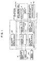
- FIG. 1 is a block diagram showing schematically the essential constitution of the control system of an exhaust purifying apparatus for an in-cylinder injection type internal combustion engine according to one embodiment of the present invention;
- FIG. 2 is a control block diagram of the in-cylinder injection type internal combustion engine according to the one embodiment of the present invention;
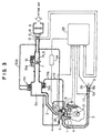
- FIG. 3 is an overall constitution diagram of the in-cylinder injection type internal combustion engine according to the one embodiment of the present invention;
- FIG. 4(a) is a schematic view for describing a lean NOx catalyst in the exhaust purifying apparatus for an in-cylinder injection type internal combustion engine according to one embodiment of the present invention and is a diagram showing the constitution of the lean NOx catalyst;
- FIG. 4(b) is a schematic view for describing a lean NOx catalyst in the exhaust purifying apparatus for an in-cylinder injection type internal combustion engine according to one embodiment of the present invention and is a diagram showing the NOx adhesion function of the lean NOx catalyst;
- FIG. 4(c) is a schematic view for describing a lean NOx catalyst in the exhaust purifying apparatus for an in-cylinder injection type internal combustion engine according to one embodiment of the present invention and is a diagram showing the NOx desorption function of the lean NOx catalyst;
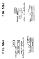
- FIG. 5(a) is a schematic view for describing the sulfur component adhesion-desorption function of the lean NOx catalyst in the exhaust purifying apparatus for an in-cylinder injection type internal combustion engine according to one embodiment of the present invention and is a diagram showing the sulfur component adhesion function;
- FIG. 5(b) is a schematic view for describing the sulfur component adhesion-desorption function of the lean NOx catalyst in the exhaust purifying apparatus for an in-cylinder injection type internal combustion engine according to one embodiment of the present invention and is a diagram showing the sulfur component desorption function;
- FIG. 6 is a flowchart showing the additional fuel injection control of the exhaust purifying apparatus for an in-cylinder injection type internal combustion engine according to the one embodiment of the present invention;
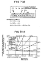
- FIG. 7(a) is a diagram for describing a chemical reaction in the exhaust purifying apparatus for an in-cylinder injection type internal combustion engine according to the one embodiment of the present invention and shows the equilibrium state of the chemical reaction; and
- FIG. 7(b) is a diagram for describing a chemical reaction in the exhaust purifying apparatus for an in-cylinder injection type internal combustion engine according to the one embodiment of the present invention and shows the relation between chemical reaction and temperature.
-
- An embodiment of the present invention will hereinafter be described by the drawings.
- Figs. 1 through 7 show an exhaust purifying apparatus (exhaust emission control system) for an in-cylinder injection type internal combustion engine according to one embodiment of the present invention.
- First, a description will be made of the in-cylinder injection type internal combustion engine equipped with the exhaust purifying apparatus of the present invention. This internal combustion engine, as shown in Fig. 3, is an internal combustion engine equipped with an intake stroke, a compression stroke, an expansion stroke, and an exhaust stroke in one operating cycle, i.e., a four-cycle engine, and is constituted as an in-cylinder injection type internal combustion engine (in-cylinder injection engine) which is of a spark ignition type and also injects fuel directly into a combustion chamber.
- To a
combustion chamber 1 anintake passage 2 and anexhaust passage 3 are connected so that they can be communicated with each other. Theintake passage 2 and thecombustion chamber 1 are controlled by an intake valve 4 so that they are opened or closed, and theexhaust passage 3 and thecombustion chamber 1 are controlled by an exhaust valve 5 so that they are opened or closed. - Also, in the
intake passage 2, an air cleaner 6 and a throttle valve 7 are provided in order from the upstream side. In theexhaust passage 3, acatalytic converter 9 for exhaust gas purification and a muffler (silencer) (not shown) are provided in order from the upstream side. Note that theintake passage 2 is provided with a surgingtank 2a. - In addition, an exhaust gas recirculation system (hereinafter referred to as an EGR system) 10 is arranged. In other words, an
exhaust recirculating passage 10b is provided so as to connect the surgingtank 2a of theintake passage 2 and the upstream side of theexhaust passage 3 together, and anEGR valve 10a is attached to thisexhaust recirculating passage 10b. - And with this
EGR valve 10a, the flow rate of emission gas (also called exhaust or exhaust gas or flue gas) can be controlled. Note that the control of theEGR valve 10a is performed according to the operating state of the engine. - Additionally, the opening angle of the throttle valve 7 varies according to the stepping-on quantity of the accelerator pedal (not shown), and with this, the quantity of air which is introduced into the
combustion chamber 1 is adjusted. Furthermore, 16 is an idle speed control valve (ISC valve), which is provided in abypass path 16A bypassing the installation portion of the throttle valve 7 of theintake passage 2. Thevalve 16 is driven to be opened and closed by a stepper motor (not shown), and finely adjusts idling engine speed primarily when the throttle valve 7 is fully closed or almost fully closed. - 50 is an air bypass valve (ABV), which is provided in a
bypass path 50A communicating theintake passage 2 on the upstream side of the throttle valve 7 and the surgingtank 2a together so as to bypass the installation portion of the throttle valve 7 of theintake passage 2. TheABV 50 adjusts an intake quantity separately from the throttle valve 7, thereby adjusting an air-fuel ratio. - An injector (fuel injection valve) 8 is arranged so that its opening faces the
combustion chamber 1, in order to inject fuel directly toward thecombustion chamber 1 of the cylinder. Also, it is a matter of course that thisinjector 8 is provided in every cylinder. For example, assuming the engine of this embodiment is an in-line four-cylinder engine, fourinjectors 8 will be provided. - With constitution such as this, the air drawn in through the air cleaner 6 in correspondence to the opening angle of the throttle valve 7 is drawn into the
combustion chamber 1 by opening the intake valve 4. Within thiscombustion chamber 1, the air drawn in is mixed with fuel injected directly from theinjector 8. The mixture has been burned within thecombustion chamber 1 by igniting aspark plug 35 at proper timing. After engine torque has been generated, the burned gases are exhausted from thecombustion chamber 1 into theexhaust passage 3 as exhaust gases. After three harmful components in the exhaust gases, CO, HC, and NOx have been purified with a catalytic converter (hereinafter also referred as to simply a catalyst) 9, the purified gases are desorbed into the atmosphere, silencing the sound made by a muffler. - Particularly, the engine of the present invention is an engine which can perform economic operation, making an air-fuel ratio lean. During a lean operation, NOx in the exhaust gases cannot be sufficiently purified with an ordinary three-way catalyst alone, so the
catalyst 9 consists of a combination of a lean NOx catalyst (NOx catalyst) 9A and a three-way catalyst 9B. In the other words, the three-way catalyst 9B with a three-way function which can purify CO, HC and NOx in exhaust gases under a stoichiometric air-fuel ratio is provided downstream of the lean NOx catalyst 9A. Among these catalysts, the lean NOx catalyst 9A is related to the present invention, and a detailed description thereof will be given later. - If the engine of the present invention is described further, this engine is constructed so that the intake flow introduced from the
intake passage 2 into thecombustion chamber 1 forms a longitudinal vortex (reverse tumble flow), and within thecombustion chamber 1, the intake flow forms a longitudinal vortex flow such as this. Therefore, for example, a small quantity of fuel is collected only in the vicinity of thespark plug 35 arranged in the center of the vertex portion of thecombustion chamber 1 by utilizing this longitudinal vortex flow, whereby a portion remote from thespark plug 35 can be made to be in an super lean air-fuel ratio state. If only the vicinity of thespark plug 35 is caused to be in a state of stoichiometric air-fuel ratio or a state of rich air-fuel ratio, fuel consumption can be suppressed realizing stable stratified-charge combustion (stratified super lean combustion). The optimum fuel injection timing in this case is at the latter period of the compression stroke in which an air flow is weak. - Also, in the case of obtaining high output from this engine, pre-mixture combustion needs to be preformed with the fuel from the
injector 8 made uniform in quality over theentire combustion chamber 1 and also with theentire combustion chamber 1 caused to be in a mixture state of stoichiometric air-fuel ratio or lean air-fuel ratio. Of course, higher output is obtained by a stoichiometric air-fuel ratio than by a lean air-fuel ratio, and even in these cases, higher output can be efficiently obtained by performing fuel injection at timing such that atomization and gasification of fuel are sufficiently performed. The optimum fuel injection timing in such cases is set so that fuel injection ends during the intake stroke so that the atomization and gasification of fuel can be promoted by taking advantage of an intake flow. - Incidentally, various kinds of sensors are provided for controlling this engine. First, on the side of the
intake passage 2, anair flow sensor 11 for detecting an intake air volume from Karman's vortex information, an intake temperature sensor 12 for detecting intake air temperature, and anatmospheric pressure sensor 13 for detecting atmospheric pressure are provided in the installation portion of the air cleaner, and a potentiometertype throttle sensor 14 for detecting an opening angle of the throttle valve 7, anidle switch 15 for detecting an idling state, etc., are provided in the installation portion of the throttle valve. - In addition, on the side of the
exhaust passage 3, anoxygen concentration sensor 17 for detecting the concentration of oxygen (O2 concentration) in exhaust gases (hereinafter referred to as simply an O2 sensor) is provided in the upstream side portion of thecatalyst 9, and also a catalytic temperature sensor (high temperature sensor) 26 for detecting temperature c.c of thecatalyst 9 or the vicinity (hereinafter referred to as catalytic temperature c.c) is provided in the downstream side portion of thecatalyst 9. - Furthermore, as for other sensors, a
water temperature sensor 19 for detecting an engine cooling water temperature is provided, and as shown in Fig. 2, a crank angle sensor (crank angle detection means) 21 for detecting a crank angle (this crankangle sensor 21 is also used as a revolution speed sensor for detecting an engine revolution speed) and a TDC sensor (cylinder identification sensor) 22 for detecting top dead center in the first cylinder (reference cylinder) are provided near cams, respectively. - And detection signals from these sensors are input to an electronic control unit (ECU) 23.
- Note that voltage signals from an
accelerator position sensor 24 for detecting an stepping-on quantity of the accelerator pedal and abattery sensor 25 for detecting a battery voltage and a signal from a cranking switch [or an ignition switch (key switch)] 20 for detecting when the engine is started are also input to theECU 23. - Incidentally, the hardware constitution of the
ECU 23 is shown in Fig. 2, and thisECU 23 is provided with a central processing unit (CPU) 27 as its main portion. To thisCPU 27, detection signals from the intake temperature sensor 12,atmospheric pressure sensor 13,throttle sensor 14, O2 sensor 17,water temperature sensor 19,accelerator position sensor 24,catalytic temperature sensor 26, and from thebattery sensor 25 are input through aninput interface 28 and an analog/digital converter 30, and also detection signals from theair flow sensor 11, crankangle sensor 21,TDC sensor 22,idle switch 15, crankingswitch 20, ignition switch, etc., are input through aninput interface 29. - Furthermore, the
CPU 27 transmits and receives data through a bus line between itself and aROM 31 for storing program data and fixed value data, aRAM 32 which is updated and overwritten in sequence, afree running counter 48, and a battery backup RAM (not shown) backed up by holding the stored contents while a battery is connected. - Note that data within the
RAM 32 will be cleared and reset if the ignition switch is turned off. - Also, fuel injection control signals, based on the result of computation in the
CPU 27, are input to the solenoids (injector solenoids) 8a of theinjectors 8 through injection drivers (fuel injection valve drive means) 34 of the cylinders (here, four cylinders). - And from the characteristics of an in-cylinder injection engine such as the above-mentioned, this engine is provided, as modes of fuel injection, with a late injection mode (late lean operating mode) which performs fuel injection during a compression stroke (particularly, the second half of a compression stroke) in order to realize a lean operation by stratified super lean combustion and enhance fuel consumption, an early injection mode (early lean operating mode) which performs fuel injection during an intake stroke (particularly, the first half of an intake stroke) in order to realize a lean operation by pre-mixture combustion and obtain output by slow acceleration, a stoichiometric mode (stoichiometric operating mode) which performs fuel injection during an intake stroke in order to realize a stoichiometric operation (stoichiometric air-fuel ratio operation) by pre-mixture combustion and enhance output in comparison with the early injection mode, and an enriched mode (open loop mode) which realizes a rich operation (in which an air-fuel ratio is less than a stoichiometric air-fuel ratio) by pre-mixture combustion and enhances output in comparison with the stoichiometric operating mode. This engine is switched according to the engine operating state. Note that a switch of the above-mentioned operating modes refers to a switch of engine combustion states.
- The exhaust purifying apparatus of the present invention is equipped in such an engine (in-cylinder injection type internal combustion engine). Here, a description will be made of the exhaust purifying apparatus of the present invention.
- First, the principles of this apparatus will be described.
- Here, the lean NOx catalyst 9A will be described. This lean NOx catalyst 9A is a catalyst of the type which purifies NOx in exhaust gases by adhering NOx to a catalyst (an occlusion type lean NOx catalyst and a trap type lean NOx catalyst). As shown in Fig. 4(a), the lean NOx catalyst 9A is constituted by alumina Al2O3 (carrier), and barium Ba, platinum Pt, and rhodium Rh carried on the carrier.
- This lean NOx catalyst 9A has a NOx adhesion-desorption function of adhering NOx in exhaust gases to itself in an oxygen concentration excess condition and desorbing the adhered NOx if oxygen concentration is reduced.
- If the NOx adhesion-desorption function in this lean NOx catalyst 9A is described, in an oxygen concentration excess condition (lean condition), as shown in Fig. 4(b), O2 first adheres to the surface of platinum Pt and then NO in exhaust gases reacts with O2 on the surface of platinum Pt and becomes
- On the other hand, part of Ba carried by the lean NOx catalyst 9A reacts with O2 and becomes barium oxide BaO. This barium oxide BaO further reacts with CO, etc. in exhaust gases and becomes a carbonate BaCO3.
- Under such a state, part of the generated NO2 further reacts with the carbonate (BaCO3) generated from barium oxide BaO and CO, and a nitrate [Ba(NO3)2] is generated and adheres to the lean NOx catalyst 9A.
- If such reaction is shown with a chemical reaction formula, it becomes like the following Reaction Formula (1):
- On the other hand, in the condition in which oxygen concentration has been reduced (rich condition), as shown in Fig. 4(c), the generation quantity of NO2 is reduced and reaction advances in the opposite direction, whereby NO2 is desorbed from the lean NOx catalyst 9A.
- In other words, the nitrite [Ba(NO3)2] adhered to the lean NOx catalyst 9A and CO in exhaust gases react with each other on the surface of platinum Pt, and NO2 and a carbonate (BaCO3) are generated, whereby NO2 is desorbed from the lean NOx catalyst 9A. If this is shown with a chemical reaction formula, it becomes like the following Reaction Formula (2):
- Next, the desorbed NO2 is deoxidized by unburned HC and CO in exhaust gases and is exhausted as N2.
- Thus, in the lean NOx catalyst 9A, a nitrite [Ba(NO3)2] and a carbonate (BaCO3) are present in a chemical equilibrium state, and a reaction in each direction will take place according to a condition near the lean NOx catalyst 9A.
- Therefore, as shown in the above-mentioned Formula (2), in a state in which residual oxygen concentration is considerably low, if a large quantity of CO which is the material of a carbonate (BaCO3) is supplied, a chemical reaction in a direction which consumes this CO, i.e., a chemical reaction in a direction which resolves a nitrite [Ba(NO3)2] and generates a carbonate (BaCO3) [a chemical reaction in a direction of reaction from right to left in Formula (2)] will advance. Therefore, with this, NOx adhered to the lean NOx catalyst 9A can be desorbed.
- For this reason, in the embodiment of the present invention, in a state in which residual oxygen concentration is considerably low, a large supply of CO which is the material of a corbonate (BaCO3) (i.e., a large supply of unburned or incompletely burned gases) is performed, thereby moving the above-mentioned chemical equilibrium, reliably removing NOx adhered to the lean NOx catalyst 9A, and maintaining the function of the lean NOx catalyst 9A. For this reason, additional fuel injection is performed as described later.
- In addition, such a lean NOx catalyst 9A also has the property of adhering SOx in exhaust gases to itself in an oxygen concentration excess condition and desorbing the adhered SOx if oxygen concentration is reduced.
- In other words, in this lean NOx catalyst 9A, as shown in Fig. 5, in an oxygen concentration excess condition, O2 adheres to the surface of platinum Pt, and the sulfur component, contained in fuel or a lubricating oil, is exhausted as SO2 after combustion. SO2 contained in the exhaust gases reacts with O2 on the surface of platinum Pt and becomes SO3 (2SO2 + O2 → 2SO3). Then, part of the generated SO3 couples with barium oxide BaO on the surface of platinum Pt, and a sulfate (BaSO4) is generated and adheres to the lean NOx catalyst 9A.
- If this is shown with a chemical reaction formula, it becomes like the following Reaction Formula (3):
- If a chemical reaction such as this takes place, Ba carried by the lean NOx catalyst 9A will be a sulfate (BaSO4) and a nitrite [Ba(NO3)2] will not be generated by this amount. Therefore, the chemical equilibrium between the sulfate (BaSO4) and the carbonate (BaCO3) will move in a direction which resolves the sulfate (BaSO4), and the NOx adhesion ability of the sulfate (BaSO4) will be reduced and therefore the performance will be reduced.
- On the other hand, in a condition in which oxygen concentration has been reduced, a portion of the sulfate (BaSO4) adhered to the lean NOx catalyst 9A and CO in exhaust gases react with each other on the surface of platinum Pt, SO3 and a carbonate (BaCO3) are generated, and SO3 is desorbed from the lean NOx catalyst 9A. If this is shown with a chemical reaction formula, it becomes like the following Reaction Formula (4):
(1/2)O2 - Then, the desorbed SO3 is deoxidized by unburned HC and CO in exhaust gases.
- Thus, in the lean NOx catalyst 9A, as shown in Fig. 7(a), a carbonate (BaCO3) and a sulfate (BaSO4) are present in a chemical equilibrium state, and a reaction in each direction becomes easy to advance according to a condition near the lean NOx catalyst 9A. In other words, Fig. 7(b) is obtained by chemical equilibrium calculation, and as shown in Fig. 7(b), as an air-fuel ratio becomes small (i.e., as an air-fuel ratio becomes lean), the sulfate (BaSO4) becomes easy to resolve and the carbonate (BaCO3) becomes easy to generate. Conversely, as an air-fuel ratio becomes great (i.e., as an air-fuel ratio becomes lean), the carbonate (BaCO3) becomes easy to resolve and the sulfate (BaSO4) becomes easy to generate.
- Also, the lean NOx catalyst 9A, in addition to a property such as this, has the property that a reaction in each direction becomes easy to advance according to temperature near the vicinity of the lean NOx catalyst 9A. In other words, the lean NOx catalyst 9A, as shown in Fig. 7(b), has the property that as temperature rises, the sulfate (BaSO4) becomes easy to resolve and the carbonate (BaCO3) becomes easy to generate. If the lean NOx catalyst 9A reaches a high temperature, part of the sulfate (BaSO4) adhered to the lean NOx catalyst 9A will resolve thermally.
- If attention is paid to such properties and if the temperature of exhaust gases supplied to the lean NOx catalyst 9A is made high (generally, about 600°C or greater), the thermal resolution of the sulfate (BaSO4) adhered to the lean NOx catalyst 9A will take place. If this is shown with a chemical reaction formula, it becomes like the following Reaction Formula (5):
- Thus, if the vicinity of the lean NOx catalyst 9A is made to be in a condition in which oxygen concentration has been reduced and is also made high in temperature (e.g., about 600°C or greater), the resolution of the sulfate (BaSO4) adhered to the lean NOx catalyst 9A by a chemical change will be promoted and also thermal resolution will take place, so the sulfur component can be reliably desorbed from the lean NOx catalyst 9A.
- Hence, the present invention, as described later, injects additional fuel during an expansion stroke, makes the temperature of exhaust gases high, and makes the condition in exhaust gases an oxygen concentration reduction condition, thereby reliably desorbing the sulfur component from the lean NOx catalyst 9A.
- In other words, in a state in which residual oxygen concentration has been made low, CO which is the material of the carbonate (BaCO3) is supplied; the nitrite [Ba(NO3)2] adhered to the lean NOx catalyst 9A is resolved and is also desorbed as NO2; and part of the sulfate (BsSO4) adhered to the lean NOx catalyst 9A is resolved by a chemical reaction and is desorbed as SO3, whereby NOx and a sulfur component (SOx) are desorbed from the lean NOx catalyst 9A. Furthermore, to desorb the sulfate (BaSO4) remaining on the lean NOx catalyst 9A, the sulfate (BaSO4) is moved in a direction in which the chemical equilibrium between the sulfate (BaSO4) and the carbonate (BaCO3) resolves the sulfate (BaSO4), by raising exhaust gas temperature, and is also resolved thermally, whereby a reduction in the NOx adhesion ability of the lean NOx catalyst 9A is prevented.
- Note that the desorbed NO2 is deoxidized by HC and is exhausted as N2.
- For this reason, additional fuel injection is made so that it is performed within an expansion stroke of each cylinder (if possible, timing near the end period of the expansion stroke is preferable), on the basis of the NOx quantity (estimated NOx quantity) and SOx quantity (estimated SOx quantity) adhered to the lean NOx catalyst 9A and, furthermore, in consideration of an ensurrance of HC and CO as a deoxidating agent in exhaust gases and the influence on an engine output torque.
- Hence, the apparatus of the present invention, as shown in Fig. 1, has a lean NOx catalyst (NOx catalyst) 9A, NOx adhesion quantity estimation means 103 for estimating the adhesion quantity of NOx adhered to the lean NOx catalyst 9A, and NOx desorption means 107A for positively desorbing NOx adhered to the lean NOx catalyst 9A.
The apparatus is also equipped with sulfur component adhesion quantity estimation means (SOx adhesion quantity estimation means) 109 for estimating the adhesion quantity of a sulfur component adhered to this lean NOx catalyst 9A, and sulfur component desorption means 107 for desorbing the sulfur component adhered to the lean NOx catalyst 9A from the lean NOx catalyst 9A. - That is, in the apparatus of the present invention, separately from the aforementioned fuel injection (main injection) for normal combustion within a combustion chamber, additional fuel is injected at timing which has little influence on engine output, and this additional fuel is burned. With this, in the NOx desorption means 107A, appropriate concentrations of HC and CO are supplied to the lean NOx catalyst 9A and a chemical reaction is promoted, whereby NOx adhered to the lean NOx catalyst 9A is desorbed. In addition, in the sulfur component desorption means 107, HC and CO similar to this NOx desorption function are supplied and also the temperature of exhaust gases is raised, whereby chemical equilibrium is moved and thermal resolution advances. With this, the sulfur component (SOx) is desorbed from the lean NOx catalyst 9A.
- Thus, the NOx desorption means 107A and the sulfur component desorption means 107 both perform the desorption of NOx and the desorption of a sulfur component by making use of fuel injection control (injector drive control). These NOx desorption means 107A and sulfur component desorption means 107, as shown in a block diagram of Fig. 1, are constituted by additional fuel injection judgment means 102, additional fuel injection control means 104, and
fuel injection valve 8, equipped as part of fuel injection control means 101 for performing fuel injection control. Note that of course, the fuel injection control means 101 is equipped with normal fuel injection control means 105 associated with main fuel injection. - Here, the constituents shown in Fig. 1 will be described.
- First, the NOx adhesion quantity estimation means 103 estimates an NOx quantity adhered to the lean NOx catalyst 9A, based on a total fuel injection quantity which is obtained from the integrated value of injector drive periods during a lean operating mode.
- Note that the NOx adhesion quantity estimation means 103 is not limited to this, but may be constituted so as to estimate the NOx quantity adhered to the lean NOx catalyst 9A, based on an NOx quantity detected by an NOx sensor.
- Also, the SOx adhesion quantity estimation means 109 estimates a SOx quantity adhered to the lean NOx catalyst 9A, based on a total fuel injection quantity which is obtained from the integrated value of injector drive periods of all operating modes.
- Note that the SOx adhesion quantity estimation means 109 is not limited to this, but may be constituted so as to estimate the SOx quantity adhered to the lean NOx catalyst 9A, based on the traveled distance of a vehicle.
- Also, the additional fuel injection judgment means 102 judges whether or not additional fuel injection control is needed in order to desorb NOx or SOx adhered to the lean NOx catalyst 9A and is constructed so that it judges whether or not a condition for starting these controls (control start condition) and a condition for releasing these controls (control release condition) have been met.
- Here, for the control start condition for desorbing NOx adhered to the lean NOx catalyst 9A, it is set such that the NOx adhesion quantity is equal to or greater than a predetermined value and also that main combustion is in a lean operating mode (e.g., a late lean operating mode) and 2-stage combustion is possible [that the air-fuel ratio (A/F) of main combustion is, for example, equal to or greater than 20 and that water temperature WT is equal to or greater than 10°C] (all are "AND" conditional).
- In this embodiment, whether the NOx adhesion quantity is equal to or greater than a predetermined value is judged based on an NOx adhesion quantity which is estimated by the NOx adhesion quantity estimation means 103, and this result of judgment is sent to the additional fuel injection judgment means 102.
- Also, whether the air-fuel ratio (A/F) of main combustion is equal to or greater than 20 (i.e., whether the air-fuel ratio is lean) is judged based on an air-fuel ratio of main combustion which is set by the normal fuel injection control means 105. For this reason, the information on an air-fuel ratio is sent from the normal fuel injection control means 105 to the additional fuel injection control means 104. The reason that this is made a condition is that since a large quantity of oxygen is present in exhaust gases, additional fuel can be reliably burned.
- Furthermore, whether water temperature WT is equal to or greater than 10°C is judged based on the detection signal from the cooling
water temperature sensor 19. For this reason, the detection information from the coolingwater temperature sensor 19 is sent to the additional fuel injection control means 104. The reason that this is made a condition is that if water temperature is too low, the occurrence of self-ignition will become difficult even if additional fuel injection were performed. - On the other hand, for the control start condition for desorbing SOx adhered to the lean NOx catalyst 9A, it is set such that the SOx adhesion quantity is equal to or greater than a predetermined value, that the air-fuel ratio (A/F) of main combustion is, for example, in a lean operating mode of 20 or more (e.g., a late lean operating mode or an early lean operating mode), and that water temperature WT is equal to or greater than 10°C (all are "AND" conditional).
- In this embodiment, whether the SOx adhesion quantity is equal to or greater than a predetermined value is judged based on a SOx adhesion quantity which is estimated by the SOx adhesion quantity estimation means 109, and this result of judgment is sent to the additional fuel injection judgment means 102.
- Note that since the judgment of whether the air-fuel ratio (A/F) of main combustion is equal to or greater than 20 and the judgment of whether water temperature WT is equal to or greater than 10°C are the same as the aforementioned control start condition for desorbing NOx, in this embodiment a description thereof is omitted.
- In this manner, the additional fuel injection judgment means 102 performs the judgment of whether or not control start conditions have been met. In the case where all of these control start conditions have been met, this additional fuel injection judgment means 102 sends a signal to the additional fuel injection control means 104 in order to perform additional fuel injection.
- Next, a description will be made of the release condition of the control for resorbing NOx or SOx adhered to the lean NOx catalyst 9A.
- First, for the control release condition for resorbing NOx adhered to the lean NOx catalyst 9A, it is set such that a predetermined period (e.g., order of 5 sec) has elapsed since additional fuel injection control was started.
- It is performed, based on the result of count of a
timer 106, whether or not a predetermined period has elapsed since additional fuel injection control was started. For this reason, if the additional fuel injection control is started, thetimer 106 will start the count, and the counted value of thetimer 106 will be sent to the additional fuel injection judgment means 102. - On the other hand, for the control release condition for resorbing SOx adhered to the lean NOx catalyst 9A, it is set such that a predetermined period (e.g., order of 5 min) has elapsed since additional fuel injection control was started.
- It is also performed, based on the result of count of the
timer 106, whether or not a predetermined period has elapsed since additional fuel injection control was started. For this reason, if the additional fuel injection control is started, thetimer 106 will start the count, and the counted value of thetimer 106 will be sent to the additional fuel injection judgment means 102. - In this manner, the additional fuel injection judgment means 102 judges whether or not the control release condition has been met, and in the case where this control release condition has been met, the
means 102 releases the additional fuel injection control. - In addition, in the case where it has been judged by the additional fuel injection judgment means 102 that additional fuel injection is needed in order to resorb NOx or SOx adhered to the lean NOx catalyst 9A, the additional fuel injection control means 104 sets the injection start time TINJ of additional fuel injection and also sets the injection period of additional fuel of each cycle.
- By adjusting these injection start time TINJ and injection period of additional fuel injection, the quantities of HC and CO which are supplied to the lean NOx catalyst 9A are adjusted. In other words, if the start time TINJ of additional fuel injection is set to a time as late as possible, the time for fuel to be atomized will be insufficient and therefore fuel oxidation can be suppressed, whereby the quantities of HC and CO which are supplied to the lean NOx catalyst 9A can be increased. Also, if the injection period of additional fuel injection is lengthened, the injection quantity of additional fuel can be increased and therefore the quantities of HC and CO which are supplied to the lean NOx catalyst 9A can be increased.
- First, a description will be made of the setting of the fuel start time TINJ and injection period of additional fuel injection for resorbing NOx.
- This injection start time TINJ of additional fuel injection is set so that additional fuel injection is performed during the middle period of an expansion stroke of each cylinder or during the expansion stroke thereafter. In other words, the injection start time TINJ of additional fuel is set, based on the detection information from the
crank angle sensor 21 as crank angle detection means, so that additional fuel injection is performed near acrank angle 90° after top dead center of piston compression between the compression and expansion strokes. - The reason that the injection start time TINJ is thus set is for reliably burning the fuel injected by additional fuel injection (hereinafter also referred to as after-burning) and thereby causing CO and a high temperature condition necessary for resorbing NOx adhered to the lean NOx catalyst 9A to occur.
- If additional fuel injection is performed at the injection start time TINJ set in this manner, pre-flame reaction products will be present with concentration near an ignition limit at a lean mixture portion formed within the combustion chamber by main combustion. Therefore, the total amount with the pre-flame reaction products which arise from additional fuel injected into a high temperature atmosphere within the cylinder exceeds an ignition limit, self-ignition takes place, and the additional fuel burns.
- Here, the point of time that the concentration of pre-flame reaction products increases and exceeds an equilibrium concentration and also that the pre-flame reaction speed advances exponentially explosively is referred to as ignition. At this point of time, flame (thermal flame) occurs. The pre-flame reaction products are active chemical reaction seeds which are effective for thrusting a chain branch reaction, and they are, for example, CHO, H2O2, OH, etc.
- Specifically, the additional fuel injection control means 104 sets injection start time TINJ by correcting for basic fuel injection start time TbINJ which is a base in additional fuel injection on this expansion stroke by cooling water temperature W, a quantity of EGR, and ignition time TIG in main combustion. For this reason, a start time map for additional fuel injection previously set based on the target A/F of main combustion is equipped in the
ECU 23. - Also, the injection period of additional fuel injection, i.e., injector drive period tPLUS is set so that the air-fuel ratio of an exhaust (exhaust target air-fuel ratio) which is supplied to the lean NOx catalyst 9A reaches the order of about 14. That is, the air-fuel ratio of the total injection quantity of additional fuel injection added to the fuel injection quantity of main combustion is set so as to reach the order of about 14. The reason that the air-fuel ratio is thus set is that there is a need to supply much HC and CO to the lean NOx catalyst 9A in order to desorb NOx from the lean NOx catalyst 9A.
- Specifically, the additional fuel injection control means 104 sets an injector drive period tPLUS by correcting for a basic drive period tB which is a base in additional fuel injection on the expansion stroke by injection start time TINJ.
- For this reason, a map for NOx desorption previously set based on the target A/F of main combustion is equipped in the
ECU 23. This map for NOx desorption is set so that the exhaust target air-fuel ratio reaches the order of about 14. And this map for NOx desorption is selected by the additional fuel injection control means 104 in setting an injector drive period tPLUS in the case where additional fuel injection for desorbing NOx is performed. - Next, a description will be made of the setting of the injection start time TINJ and injection period of additional fuel injection for resorbing SOx.
- In this case, the injection start time TINJ of additional fuel injection is set to a time such that exhaust gas temperature reaches approximately 600°C or greater. This is for promoting the chemical change of a sulfate (BaSO4) adhered to the lean NOx catalyst 9A and also promoting thermal resolution, by causing exhaust gas temperature to reach approximately 600°C or greater.
- Note that in this embodiment of the present invention, the additional fuel injection control will end if it continues for a predetermined period (order of about 5 min), and therefore, there is a little possibility of an excessive rise in the temperature of the lean NOx catalyst 9. However, in consideration of the durability of the lean NOx catalyst 9A and in order to prevent an excessive rise in the temperature of the lean NOx catalyst 9A reliably, it is preferable to adjust exhaust gas temperature, based on detection information from the
catalytic temperature sensor 26, so that it does not reach approximately 800°C or greater. - This additional fuel injection for desorbing SOx absorbed to the lean NOx catalyst 9A is performed under a lean combustion operation. Therefore, when it is estimated that a certain quantity or greater of SOx has been absorbed to the lean NOx catalyst 9A, this additional fuel injection will be performed immediately if the operating mode is a lean operating mode. If the operating mode is another operating mode (stoichiometric feedback operating mode or enriched open loop operating mode), the additional fuel injection will wait for a lean operation mode and be performed.
- Also, even when the operating mode is switched from a lean operating mode to another operating mode before such additional fuel injection continues for a predetermined period T1 (here, about 5 min), the additional fuel injection is stopped once, and thereafter, the additional fuel injection is again performed when the operating mode is switched to a lean operating mode. In this case, if the accumulated period of the additional fuel injection reaches a predetermined period T2, it is assumed that the present additional fuel injection for desorbing SOx has been completed.
- However, this additional fuel injection is performed by raising the atmosphere temperature of the lean NOx catalyst 9A up to a predetermined temperature region and also by making the atmosphere of the lean NOx catalyst 9A a condition of deoxidization, and it takes a certain time until the atmosphere temperature of the lean NOx catalyst 9A rises up to a predetermined level since the additional fuel injection was started. Therefore, in the case where the additional fuel injection is caused to continue for a predetermined period T1 (here, about 5 min), the surroundings of the lean NOx catalyst 9A reach the temperature of atmosphere which can desorb SOx, for only a period T1 - t1 obtained by subtracting time t1 required for the atmosphere temperature of the lean NOx catalyst 9A to rise to a predetermined level from the predetermined period T1.
- If the additional fuel injection is performed while being interrupted in the middle of the injection, the time t1 required for the atmosphere temperature of the lean NOx catalyst 9A to rise to a predetermined level will be required each time, as described above. (But, if the interval of interruption is short, the time t1 required to rise to this predetermined level will also shorten.) Hence, in the case where additional fuel injection is performed while being interrupted in the middle of the injection, it is desirable to set a predetermined period T2 in consideration of such time required for a rise in temperature.
- In this embodiment, the injection start time TINJ of additional fuel is set, based on detection information from the
crank angle sensor 21 as crank angle detection means, so that additional fuel injection is performed near acrank angle 90° after top dead center of piston compression between the compression and expansion strokes. - The reason that the injection start time TINJ is thus set is for reliably burning the fuel injected by additional fuel injection (hereinafter also referred to as after-burning) and thereby raising exhaust gas temperature.
- If additional fuel injection is performed at the injection start time TINJ set in this manner, as described above, pre-flame reaction products are present with a concentration near an ignition limit at a lean mixture portion formed within the combustion chamber by main combustion. Therefore, the total amount with the pre-flame reaction products which arise from additional fuel injected into a high temperature atmosphere within the cylinder exceeds an ignition limit, self-ignition takes place, and the additional fuel burns.
- The specific setting of the injection start time TINJ is similar to the above-mentioned setting of the injection start time TINJ of the additional fuel injection for desorbing NOx.
- Also, the injection period of additional fuel injection, i.e., injector drive period tPLUS is set so that the air-fuel ratio of an exhaust (exhaust target air-fuel ratio) which is supplied to the lean NOx catalyst 9A reaches the order of about 11. That is, the air-fuel ratio of the total injection quantity of additional fuel injection added to the fuel injection quantity of main combustion is set so as to reach the order of about 11. The reason that the air-fuel ratio is thus set is for causing additional fuel to reliably burn to make exhaust gas temperature high and also for supplying HC and CO as a deoxidating agent, in order to desorb SOx from the lean NOx catalyst 9A.
- Specifically, the additional fuel injection control means 104 sets an injector drive period tPLUS by correcting for a basic drive period tB which is a base in additional fuel injection on the expansion stroke by injection start time TINJ.
- For this reason, a map for SOx desorption previously set based on the target A/F of main combustion is equipped in the
ECU 23. This map for SOx desorption is set so that the exhaust target air-fuel ratio reaches the order of about 11. And this map for SOx desorption is selected by the additional fuel injection control means 104 in setting an injector drive period tPLUS in the case where additional fuel injection for desorbing SOx is performed. - Note that in this case, although NOx and SOx adhered to the lean NOx catalyst 9A both need to be desorbed, desorption of SOx has priority and a map for SOx desorption is selected.
- Incidentally, if the fuel injection control in the normal fuel injection control means 105 is described, this normal fuel injection control means 105 has a function of setting a fuel injection quantity in a normal fuel injection, based on information from
various sensors 108. - In other words, the fuel injection quantity is set as a fuel injection period (which is a time to drive an injector and referred to as an injector drive pulse width in actual control) tAU. Even in the case of a stoichiometric mode and an early injection mode and even in the case of a late injection mode, a basic drive period tP is computed based on engine load (intake air quantity per 1 stroke) Q/Ne, a target air-fuel ratio (A/F which will hereinafter be referred to as AF), etc., and the fuel injection period tAU is set in consideration of the engine cooling water temperature detected with the
water temperature sensor 19, intake temperature detected with the intake temperature sensor 12, fuel correction coefficient f which is set according to the atmospheric pressure detected with theatmospheric pressure sensor 13, injector dead time tD, etc. - Since the exhaust purifying apparatus according to this embodiment of the present invention is constituted as described above, control associated with exhaust purification is performed, for example, as shown in a flowchart of Fig. 6. First, in step S10 an NOx adhesion quantity adhered to the lean NOx catalyst 9A is estimated by the NOx adhesion quantity estimation means (NOx adhesion quantity estimation means) 103. In step S20 a SOx adhesion quantity adhered to the lean NOx catalyst 9A is estimated by the SOx adhesion quantity estimation means (SOx adhesion quantity estimation means) 109.
- And in step S30, the additional fuel injection judgment means 102 judges whether or not the NOx adhesion quantity estimated by the NOx adhesion quantity estimation means 103 is equal to or greater than a predetermined quantity. As this result of judgment, in the case where it has been judged that the estimated NOx adhesion quantity is equal to or greater than a predetermined quantity, step S30 advances to step S40 and a flag N for NOx desorption is set to 1.
- Note that the flag N for NOx desorption goes to 1 when the map for NOx desorption is selected and goes to 0 when the map for NOx desorption is not selected. Also, it is set to 0 at the time of initial setting.
- Next, in step S50 the additional fuel injection judgment means 102 judges whether or not the SOx adhesion quantity estimated by the SOx adhesion quantity estimation means 109 is equal to or greater than a predetermined quantity. As this result of judgment, in the case where it has been judged that the estimated SOx adhesion quantity is equal to or greater than a predetermined quantity, step S50 advances to step S60 and a flag S for SOx desorption is set to 1.
- Note that the flag S for SOx desorption goes to 1 when the map for SOx desorption is selected and goes to 0 when the map for SOx desorption is not selected. Also, it is set to 0 at the time of initial setting.
- On the other hand, in step S30, when it is judged that the NOx adhesion quantity is not equal to or greater than a predetermined value, this step advances to step S50, in which it is judged whether the SOx adhesion quantity is equal to or greater than a predetermined value.
- Also, in step S50, when it is judged that the SOx adhesion quantity is not equal to or greater than a predetermined value, this step advances to step S70.
- And in step S70, the additional fuel injection judgment means 102 judges whether or not an air-fuel ratio is equal to or greater than 20. When the air-fuel ratio is equal to or greater than 20, this step advances to step S80.
- In step S80 the additional fuel injection judgment means 102 judges whether or not the water temperature detected by the cooling
water temperature 19 is equal to or greater than 10°C. When the water temperature WT is equal to or greater than 10°C, this step advances to step S90. - And in step S90, the additional fuel injection control means 104 reads the injection start time TINJ and injector drive period tPLUS of the additional fuel injection on the expansion stroke from the map.
- In this case, when the flag S for SOx desorption is 1 (at this time, the flag N for NOx desorption is also 1), the map for SOx desorption is selected and the injector drive period tPLUS is set by this map for SOx desorption. On the other hand, when the flag S for SOx desorption is 0 (at this time, the flag N for NOx desorption is 1), the map for NOx desorption is selected and the injector drive period tPLUS is set by this map for NOx desorption.
- In this manner, after the injection start time TINJ and injector drive period tPLUS of the additional fuel injection on the expansion stroke have been set, step S90 advances to step S100, and based on these injection start time TINJ and injector drive period tPLUS, the additional fuel injection on the expansion stroke is performed.
- If the additional fuel injection is started, the
timer 106 will be started at the same time. Whether or not a predetermined period has elapsed since the additional fuel injection was started is judged by whether or not the counted value of thetimer 106 has exceeded a predetermined value. As this result of judgment, in the case where it has been judged that a predetermined time has elapsed since the additional fuel injection was started, the additional fuel injection on the expansion stroke is ended on the assumption that NOx or SOx adhering to the lean NOx catalyst 9A was desorbed sufficiently. - And in step S110, the flag N for NOx desorption and the flag S for SOx desorption are reset (N = 0 and S = 0), and this step returns.
- On the other hand, in the case where in step S70 it is judged that an air-fuel ratio is not equal to or greater than 20 and in the case where in step S80 it is judged that the water temperature WT detected by the cooling
water temperature 19 is not equal to or greater than 10°C, both cases return without performing the additional fuel injection of the expansion stroke for desorbing NOx or SOx adhered to the lean NOx catalyst 9A. - Since the exhaust purifying apparatus of the present invention is thus operated, it can make additional fuel burn reliably and make the temperature of exhaust gases rise without providing an additional device. Therefore, the sulfur component adhered to the lean NOx catalyst 9A can be reliably desorbed. With this, there is an advantage that the durability of the lean NOx catalyst 9A can be enhanced.
- Also, since warm-up time is unnecessary and exhaust gas temperature can be made to rise in a short period, there is also an advantage that the desorption of the sulfur component from the lean NOx catalyst 9A by the sulfur component desorption means 107 can be performed in a short period.
- In addition, since the additional fuel injection is performed according to an adhesion quantity of SOx estimated by the SOx adhesion quantity estimation means, there is also an advantage that SOx adhered to the lean NOx catalyst 9A can be efficiently desorbed, a reduction in the NOx adhesion ability of the lean NOx catalyst 9A can be suppressed, and the performance of the lean NOx catalyst 9A can be further enhanced.
- Additionally, since CO can be reliably supplied to the lean NOx catalyst 9A without causing torque fluctuation to occur, the reaction of resorbing NOx adhered to the lean NOx catalyst 9A is promoted, whereby the lean NOx catalyst 9A can be reliably regenerated. With this, there is an advantage that the performance of the lean NOx catalyst 9A can be enhanced. Also, by varying the injection time of additional fuel injection, the concentrations of HC and CO in exhaust gases can be varied according to the quantity of NOx which is estimated to have adhered to the lean NOx catalyst 9A, so there is an advantage that appropriate concentrations of HC and CO can be supplied with respect to the quantity of NOx adhered to the lean NOx catalyst 9A.
- In other words, in the case where there is a large quantity of NOx which is estimated to have adhered to the lean NOx catalyst 9A, the injection period of the additional fuel injection on the expansion stroke is made as late as possible, thereby degrading atomization of fuel. With this, oxidization of fuel is suppressed and high concentrations of HC and CO are generated.
- Thus, since the concentrations of HC and CO in exhaust gases can be varied, there is an advantage that NOx adhering to the lean NOx catalyst 9A can be efficiently desorbed according to the quantity of NOx which is estimated to have adhered to the lean NOx catalyst 9A.
- In addition, since additional fuel injection has been performed on the expansion stroke, a fluctuation in the output torque of the engine is reduced. Particularly, by performing the additional fuel injection in the second half of the expansion stroke, with this additional fuel injection there is also an advantage that there is almost no occurrence of torque fluctuation.
- For this reason, the injection quantity of additional fuel injection can be set according to the quantities of HC and CO which are desired to be supplied to the lean NOx catalyst 9A, and much HC and CO can be supplied to the lean NOx catalyst 9A during 1 cycle, so NOx can be reliably desorbed from the lean NOx catalyst 9A.
- In addition, since additional fuel injection can be performed if the air-fuel ratio of main combustion is lean, there is an advantage that the desorption of NOx or SOx from the lean NOx catalyst 9A can be performed in a wide operating state (e.g., during normal operation).
- In the exhaust purifying apparatus of the embodiment of the present invention, although the adhesion quantity of a sulfur component to an NOx catalyst is estimated by surface component adhesion quantity estimation means, sulfur desorption means, for example, may be periodically operated during a specific operation without providing this estimation means specially.
- In addition, in the embodiment of the present invention, while additional fuel injection is performed during the middle period of the expansion stroke or thereafter, the present invention is not limited to this. If additional fuel can be reliably burned suppressing torque fluctuation, the additional fuel injection may be performed during another period of the expansion stroke or the exhaust stroke.
- Particularly, in the case where the temperature of cooling water is low, even if additional fuel injection were performed during the middle period of the expansion stroke or thereafter, the occurrence of self-ignition will be difficult. Therefore, in this case, additional fuel injection may be performed within the remaining flame period of main combustion in the first half of the expansion stroke (e.g., near a
crank angle 35° to 50° after top dead point of piston compression). If done in this way, even in the case where the temperature of cooling water is low, additional fuel can be reliably burned (after-burning). - Also, the exhaust purifying apparatus of this embodiment is constituted so that it is equipped with the NOx adhesion quantity estimation means 103 and the SOx adhesion quantity estimation means 109 to perform the control of desorbing NOx from the lean NOx catalyst 9A and also perform the control of desorbing SOx from the lean NOx catalyst 9A. But, the present invention may be constituted so that it is equipped with the SOx adhesion quantity estimation means 109 alone to perform only the control of desorbing SOx from the lean NOx catalyst 9A.
- In addition, in the exhaust purifying apparatus of this embodiment, when SOx is desorbed from the lean NOx catalyst 9A, an exhaust target air-fuel ratio is set so that it reaches the order of about 14, in order to make exhaust gas temperature high and promote the resolution reaction of a nitride. But, if the exhaust target air-fuel ratio is set to the order of about 11, it will be possible to make exhaust gas temperature even higher and make even higher the concentrations of HC and CO which are supplied. At the same time the desorption of SOx from the lean NOx catalyst 9A can be further promoted, the desorption of NOx from the lean NOx catalyst 9A can be also promoted and also SOx and NOx after desorption can be deoxidized.
- Additionally, in the exhaust purifying apparatus of this embodiment, although the lean NOx catalyst 9A carries platinum Pt and barium Ba on a carrier, the present invention is not limited to this, but it may carry other precious metals and metals on a carrier.
- Also, in the exhaust purifying apparatus of this embodiment, the start and end of additional fuel injection are controlled by whether or not the additional fuel injection on the expansion stroke has continued for a predetermined period. However, for example, the start and end of additional fuel injection may be controlled by detecting exhaust gas temperature with a temperature sensor and by whether or not this exhaust gas temperature has continued in a state of 550°C or more for a predetermined period. With this, a degradation in fuel consumption can be prevented.
- Furthermore, in the exhaust purifying apparatus of this embodiment, while expansion stroke injection is performed in sequence in each cylinder, the present invention may be set so that expansion stroke injection is performed only in a specific cylinder of four cylinders. Also, the exhaust purifying apparatus of this embodiment may be set so that expansion stroke injection is performed every predetermined cycle (e.g., once every two cycles).
- Also, although the exhaust purifying apparatus of this embodiment is equipped in a spark-ignition type in-cylinder injection engine, the present invention is not limited to this. For example, it may be equipped in diesel engines.
- By adopting the present invention in an exhaust purifying apparatus for an in-cylinder injection type internal combustion engine, additional fuel is made to reliably burn and exhaust gas temperature can be made to rise, without providing an additional device. Therefore, it is considered that a sulfur component adhered to an NOx catalyst can be reliably desorbed and that the durability of the NOx catalyst can be enhanced.
Claims (3)
- An exhaust purifying apparatus of an in-cylinder injection type internal combustion engine which is equipped with a fuel injection valve (8) for injecting fuel directly into a combustion chamber and in which fuel is injected during at least a compression stroke by said fuel injection valve (8) to perform stratified-charge combustion, the exhaust purifying apparatus for the in-cylinder injection type internal combustion engine comprising:wherein said sulfur component desorption means (107) injects additional fuel during an expansion stroke in addition to main injection for said stratified-charge combustion and also burns said additional fuel again within said combustion chamber so that exhaust gas temperature is raised to a predetermined temperature or beyond, whereby said sulfur component is desorbed.an NOx catalyst (9A) provided in an exhaust passage of said internal combustion engine, the NOx catalyst adhering NOx to itself in an oxygen concentration excess condition and desorbing NOx in an oxygen concentration reduction condition; andsulfur component desorption means (107) for desorbing a sulfur component from said NOx catalyst (9A);
- The exhaust purifying apparatus of the in-cylinder injection type internal combustion engine, as set forth in claim 1, further comprising:wherein said sulfur component desorption means (107) is operated according to output from said sulfur component adhesion quantity estimation means (109).a sulfur component adhesion quantity estimation means (109) for estimating an adhesion quantity of a sulfur component which adheres to said NOx catalyst (9A) and reduces an NOx adhesion ability of said NOx catalyst (9A);
- The exhaust purifying apparatus of the in-cylinder injection type internal combustion engine, as set forth in claim 2, wherein said sulfur component adhesion quantity estimation means (109) estimates an adhesion quantity of the sulfur component, based on a total fuel injection quantity which is obtained from an integrated value of injector drive periods of all operating modes.
Applications Claiming Priority (4)
| Application Number | Priority Date | Filing Date | Title |
|---|---|---|---|
| JP9098093A JP3067685B2 (en) | 1997-03-31 | 1997-03-31 | Exhaust purification system for spark ignition type direct injection type internal combustion engine |
| JP98093/97 | 1997-03-31 | ||
| JP9809397 | 1997-03-31 | ||
| PCT/JP1998/000546 WO1998044245A1 (en) | 1997-03-31 | 1998-02-10 | Exhaust gas purifying device of cylinder injection internal combustion engine |
Publications (3)
| Publication Number | Publication Date |
|---|---|
| EP0903481A1 EP0903481A1 (en) | 1999-03-24 |
| EP0903481A4 EP0903481A4 (en) | 2000-06-21 |
| EP0903481B1 true EP0903481B1 (en) | 2003-09-03 |
Family
ID=14210738
Family Applications (1)
| Application Number | Title | Priority Date | Filing Date |
|---|---|---|---|
| EP98901578A Expired - Lifetime EP0903481B1 (en) | 1997-03-31 | 1998-02-10 | Exhaust gas purifying device of cylinder injection internal combustion engine |
Country Status (6)
| Country | Link |
|---|---|
| US (1) | US6173571B1 (en) |
| EP (1) | EP0903481B1 (en) |
| JP (1) | JP3067685B2 (en) |
| KR (1) | KR100318001B1 (en) |
| DE (1) | DE69817718T2 (en) |
| WO (1) | WO1998044245A1 (en) |
Families Citing this family (50)
| Publication number | Priority date | Publication date | Assignee | Title |
|---|---|---|---|---|
| JP3424557B2 (en) * | 1997-08-06 | 2003-07-07 | マツダ株式会社 | Engine exhaust purification device |
| JP3805098B2 (en) * | 1998-03-26 | 2006-08-02 | 株式会社日立製作所 | Engine exhaust gas purification control device |
| US6336320B1 (en) * | 1998-07-10 | 2002-01-08 | Toyota Jidosha Kabushiki Kaisha | Exhaust gas purification device for an internal combustion engine |
| US6289672B1 (en) * | 1998-07-21 | 2001-09-18 | Toyota Jidosha Kabushiki Kaisha | Exhaust gas purification device for an internal combustion engine |
| DE19852240A1 (en) * | 1998-11-12 | 2000-05-18 | Volkswagen Ag | Monitoring method for NOx storage catalytic converters and exhaust gas purification device for carrying out this method |
| IT1304135B1 (en) * | 1998-11-26 | 2001-03-07 | Magneti Marelli Spa | INJECTION AND IGNITION CONTROL METHOD IN A DIRECT INJECTION THERMAL ENGINE TO ACCELERATE THE HEATING OF THE |
| JP3225957B2 (en) | 1999-02-02 | 2001-11-05 | トヨタ自動車株式会社 | Internal combustion engine |
| JP3680612B2 (en) * | 1999-02-09 | 2005-08-10 | マツダ株式会社 | In-cylinder injection engine control device |
| JP2000282848A (en) * | 1999-03-30 | 2000-10-10 | Nissan Motor Co Ltd | Exhaust emission control device for internal combustion engine |
| DE19920515C2 (en) * | 1999-05-05 | 2003-03-20 | Daimler Chrysler Ag | Emission control system with nitrogen oxide adsorber and Desulfatisierungsverfahren this |
| EP1059428B1 (en) * | 1999-06-08 | 2005-12-14 | Honda Giken Kogyo Kabushiki Kaisha | Exhaust gas purifying apparatus and controller for internal combustion engine |
| DE19930086B4 (en) * | 1999-06-30 | 2004-08-19 | Robert Bosch Gmbh | Method for operating an internal combustion engine |
| JP3304929B2 (en) * | 1999-08-26 | 2002-07-22 | トヨタ自動車株式会社 | Internal combustion engine |
| JP2001090594A (en) * | 1999-09-22 | 2001-04-03 | Mazda Motor Corp | Control device for engine |
| JP3642273B2 (en) * | 1999-10-21 | 2005-04-27 | 日産自動車株式会社 | Exhaust gas purification system |
| DE19954549C2 (en) * | 1999-11-12 | 2001-12-20 | Daimler Chrysler Ag | Process for operating an exhaust gas cleaning system with nitrogen oxide adsorber and loading sensor |
| DE19959605A1 (en) * | 1999-12-10 | 2001-06-13 | Volkswagen Ag | Device and method for NOx and / or SOx regeneration of a NOx storage catalytic converter |
| JP3607980B2 (en) * | 1999-12-16 | 2005-01-05 | トヨタ自動車株式会社 | Internal combustion engine |
| US6928808B2 (en) * | 2000-02-17 | 2005-08-16 | Volkswagen Atkiengesellschaft | Device and method for controlling the nox regeneration of a nox storage catalyst |
| EP1201302B1 (en) | 2000-02-22 | 2007-08-08 | Mazda Motor Corporation | Exhaust gas purifying catalyst and production method for exhaust gas purifying catalyst |
| JP2001241341A (en) * | 2000-02-28 | 2001-09-07 | Hitachi Ltd | Exhaust emission control device and exmission control method for internal combustion engine |
| US6490855B1 (en) * | 2000-04-06 | 2002-12-10 | Ford Global Technologies, Inc. | Fueling control during emission control device purging |
| FR2812034B1 (en) * | 2000-07-21 | 2003-03-21 | Renault | FUEL INJECTION PROCESS |
| FR2812687B1 (en) * | 2000-08-03 | 2003-04-04 | Peugeot Citroen Automobiles Sa | SYSTEM FOR AIDING THE REGENERATION OF A CATALYST INTEGRATED IN AN EXHAUST SYSTEM OF A MOTOR VEHICLE |
| FR2812690B1 (en) * | 2000-08-03 | 2003-04-04 | Peugeot Citroen Automobiles Sa | SYSTEM FOR AIDING THE REGENERATION OF A CATALYST INTEGRATED IN AN EXHAUST SYSTEM OF A MOTOR VEHICLE |
| JP3546829B2 (en) | 2000-10-04 | 2004-07-28 | トヨタ自動車株式会社 | Compression ignition type internal combustion engine |
| JP3981915B2 (en) | 2001-04-03 | 2007-09-26 | 日産自動車株式会社 | Exhaust gas purification system |
| JP2002364415A (en) * | 2001-06-07 | 2002-12-18 | Mazda Motor Corp | Exhaust emission control device for engine |
| US6490860B1 (en) * | 2001-06-19 | 2002-12-10 | Ford Global Technologies, Inc. | Open-loop method and system for controlling the storage and release cycles of an emission control device |
| US6591604B2 (en) * | 2001-06-19 | 2003-07-15 | Ford Global Technologies, Llc | Oxygen storage capacity estimation |
| US6536209B2 (en) * | 2001-06-26 | 2003-03-25 | Caterpillar Inc | Post injections during cold operation |
| JP2003090250A (en) * | 2001-09-18 | 2003-03-28 | Nissan Motor Co Ltd | Control device for diesel engine |
| DE10149236A1 (en) * | 2001-10-05 | 2003-04-30 | Bosch Gmbh Robert | Method for operating an internal combustion engine, in particular a motor vehicle |
| JP3885545B2 (en) * | 2001-10-12 | 2007-02-21 | 日産自動車株式会社 | Exhaust gas purification device for internal combustion engine |
| JP2003206785A (en) * | 2002-01-18 | 2003-07-25 | Hitachi Ltd | Method and device for controlling engine |
| JP4114425B2 (en) * | 2002-07-29 | 2008-07-09 | 三菱ふそうトラック・バス株式会社 | Engine control device |
| JP4135428B2 (en) * | 2002-08-01 | 2008-08-20 | 日産自動車株式会社 | Apparatus and method for exhaust gas purification of internal combustion engine |
| JP3925357B2 (en) * | 2002-08-30 | 2007-06-06 | いすゞ自動車株式会社 | Control method of exhaust gas purification system |
| US6981370B2 (en) * | 2002-12-03 | 2006-01-03 | Caterpillar Inc | Method and apparatus for PM filter regeneration |
| JP4385593B2 (en) * | 2002-12-10 | 2009-12-16 | トヨタ自動車株式会社 | Exhaust gas purification device for internal combustion engine |
| JP4357863B2 (en) * | 2003-04-14 | 2009-11-04 | 株式会社デンソー | Multi-cylinder internal combustion engine cylinder-by-cylinder air-fuel ratio calculation device |
| JP2005048746A (en) * | 2003-07-31 | 2005-02-24 | Nissan Motor Co Ltd | Fuel control device for internal combustion engine |
| JP4415648B2 (en) | 2003-11-05 | 2010-02-17 | いすゞ自動車株式会社 | Sulfur purge control method and exhaust gas purification system |
| US7191591B2 (en) * | 2003-11-06 | 2007-03-20 | International Engine Intellectual Property Company, Llc | Attenuation of engine harshness during lean-to rich transitions |
| US7197867B2 (en) * | 2004-10-04 | 2007-04-03 | Southwest Research Institute | Method for the simultaneous desulfation of a lean NOx trap and regeneration of a Diesel particulate filter |
| US7117843B2 (en) * | 2004-10-07 | 2006-10-10 | International Engine Intellectual Property Company, Llc | Emission reduction in a diesel engine using an alternative combustion process and a low-pressure EGR loop |
| JP4100440B2 (en) * | 2006-09-26 | 2008-06-11 | トヨタ自動車株式会社 | Control device for hybrid vehicle |
| US8302380B2 (en) * | 2009-06-16 | 2012-11-06 | GM Global Technology Operations LLC | Desulfation systems and methods for lean NOx trap (LNT) |
| RU2460572C1 (en) * | 2011-05-04 | 2012-09-10 | Государственное образовательное учреждение высшего профессионального образования "Самарский государственный университет путей сообщения" (СамГУПС) | Method for purification of gaseous combustion products |
| CN112065540B (en) * | 2020-09-09 | 2021-09-21 | 安徽江淮汽车集团股份有限公司 | NSC desulfurization method |
Family Cites Families (23)
| Publication number | Priority date | Publication date | Assignee | Title |
|---|---|---|---|---|
| JPS63150441A (en) | 1986-12-15 | 1988-06-23 | Toyota Motor Corp | Removing method for sulfur compound adhered to catalyst |
| JP2748686B2 (en) * | 1990-11-16 | 1998-05-13 | トヨタ自動車株式会社 | In-cylinder direct injection spark ignition engine |
| JP2605586B2 (en) | 1992-07-24 | 1997-04-30 | トヨタ自動車株式会社 | Exhaust gas purification device for internal combustion engine |
| JP2605553B2 (en) * | 1992-08-04 | 1997-04-30 | トヨタ自動車株式会社 | Exhaust gas purification device for internal combustion engine |
| JP2745985B2 (en) | 1992-08-13 | 1998-04-28 | トヨタ自動車株式会社 | Exhaust gas purification device for internal combustion engine |
| WO1994017291A1 (en) * | 1993-01-19 | 1994-08-04 | Toyota Jidosha Kabushiki Kaisha | Exhaust gas cleaning device for an internal combustion engine |
| EP0621400B1 (en) * | 1993-04-23 | 1999-03-31 | Daimler-Benz Aktiengesellschaft | Air compressing injection internal combustion engine with an exhaust gas treating device for reducing nitrous oxides |
| JP3404846B2 (en) | 1993-12-28 | 2003-05-12 | トヨタ自動車株式会社 | Control device for internal combustion engine with automatic transmission |
| JP3412314B2 (en) | 1995-02-13 | 2003-06-03 | トヨタ自動車株式会社 | Exhaust gas purification device for internal combustion engine |
| JP3574203B2 (en) | 1994-04-12 | 2004-10-06 | トヨタ自動車株式会社 | Exhaust gas purification method for internal combustion engine |
| JP3334396B2 (en) | 1995-01-20 | 2002-10-15 | トヨタ自動車株式会社 | Exhaust gas purification device for internal combustion engine |
| JPH08105318A (en) | 1994-10-05 | 1996-04-23 | Mitsubishi Motors Corp | Internal combustion engine provided with exhaust purifying catalyst |
| JP3030412B2 (en) | 1994-06-17 | 2000-04-10 | 三菱自動車工業株式会社 | Exhaust purification catalyst device for internal combustion engine |
| GB2294334B (en) * | 1994-09-29 | 1997-07-02 | Fuji Heavy Ind Ltd | Catalyst activation control system |
| JPH08100638A (en) * | 1994-09-29 | 1996-04-16 | Fuji Heavy Ind Ltd | Catalytic activation control device for fuel cylinder injection engine |
| DE69520567T2 (en) | 1995-01-20 | 2001-08-23 | Toyota Motor Co Ltd | EXHAUST GAS CLEANING METHOD FOR AN INTERNAL COMBUSTION ENGINE |
| JP3052777B2 (en) | 1995-04-27 | 2000-06-19 | 三菱自動車工業株式会社 | In-cylinder injection internal combustion engine |
| JP3671455B2 (en) | 1995-04-28 | 2005-07-13 | 株式会社デンソー | Exhaust gas purification device for internal combustion engine |
| JP3757433B2 (en) | 1995-05-18 | 2006-03-22 | 三菱自動車工業株式会社 | Engine exhaust gas purification device |
| JP3870430B2 (en) * | 1995-07-14 | 2007-01-17 | 三菱自動車工業株式会社 | In-cylinder internal combustion engine |
| US5704339A (en) * | 1996-04-26 | 1998-01-06 | Ford Global Technologies, Inc. | method and apparatus for improving vehicle fuel economy |
| US5839275A (en) * | 1996-08-20 | 1998-11-24 | Toyota Jidosha Kabushiki Kaisha | Fuel injection control device for a direct injection type engine |
| US5910096A (en) * | 1997-12-22 | 1999-06-08 | Ford Global Technologies, Inc. | Temperature control system for emission device coupled to direct injection engines |
-
1997
- 1997-03-31 JP JP9098093A patent/JP3067685B2/en not_active Expired - Lifetime
-
1998
- 1998-02-10 US US09/180,448 patent/US6173571B1/en not_active Expired - Lifetime
- 1998-02-10 DE DE69817718T patent/DE69817718T2/en not_active Expired - Lifetime
- 1998-02-10 EP EP98901578A patent/EP0903481B1/en not_active Expired - Lifetime
- 1998-02-10 WO PCT/JP1998/000546 patent/WO1998044245A1/en active IP Right Grant
- 1998-02-10 KR KR1019980709742A patent/KR100318001B1/en not_active IP Right Cessation
Also Published As
| Publication number | Publication date |
|---|---|
| EP0903481A1 (en) | 1999-03-24 |
| DE69817718T2 (en) | 2004-07-15 |
| KR100318001B1 (en) | 2002-04-17 |
| WO1998044245A1 (en) | 1998-10-08 |
| DE69817718D1 (en) | 2003-10-09 |
| EP0903481A4 (en) | 2000-06-21 |
| KR20000016174A (en) | 2000-03-25 |
| US6173571B1 (en) | 2001-01-16 |
| JP3067685B2 (en) | 2000-07-17 |
| JPH10274031A (en) | 1998-10-13 |
Similar Documents
| Publication | Publication Date | Title |
|---|---|---|
| EP0903481B1 (en) | Exhaust gas purifying device of cylinder injection internal combustion engine | |
| US7111452B2 (en) | Control device of hydrogen engine | |
| JP3702924B2 (en) | Exhaust purification device | |
| EP1148215A1 (en) | Exhaust emission control device of internal combustion engine | |
| EP0908613A2 (en) | Engine exhaust gas control system having NOx catalyst | |
| JP3870430B2 (en) | In-cylinder internal combustion engine | |
| JP3460503B2 (en) | Exhaust gas purification device for in-cylinder injection internal combustion engine | |
| JPH08105318A (en) | Internal combustion engine provided with exhaust purifying catalyst | |
| US10933374B2 (en) | Exhaust emission control device, method and computer program product for an engine | |
| JP3085192B2 (en) | Engine exhaust gas purifier | |
| JP3873537B2 (en) | Exhaust gas purification device for internal combustion engine | |
| JP4161429B2 (en) | Lean combustion internal combustion engine | |
| JP4345202B2 (en) | Exhaust gas purification device for internal combustion engine | |
| JP4134395B2 (en) | In-cylinder internal combustion engine | |
| JPH11229864A (en) | Exhaust emission control device of internal combustion engine | |
| JP3867182B2 (en) | Internal combustion engine | |
| JP2003041968A (en) | Control system for internal combustion engine | |
| JP2000161045A (en) | Exhaust emission control device for internal combustion engine | |
| JP2004360569A (en) | Exhaust gas purification control system of internal combustion engine | |
| JP3835071B2 (en) | Exhaust gas purification device for internal combustion engine | |
| JP2004232555A (en) | Exhaust gas cleaning system for internal-combustion engine | |
| JP4457442B2 (en) | Exhaust gas purification device for internal combustion engine | |
| JP4231969B2 (en) | In-cylinder internal combustion engine | |
| JP2001152912A (en) | Air-fuel ratio control device for lean-burn internal combustion engine | |
| JPH11229858A (en) | Internal combustion engine |
Legal Events
| Date | Code | Title | Description |
|---|---|---|---|
| PUAI | Public reference made under article 153(3) epc to a published international application that has entered the european phase |
Free format text: ORIGINAL CODE: 0009012 |
|
| 17P | Request for examination filed |
Effective date: 19981110 |
|
| AK | Designated contracting states |
Kind code of ref document: A1 Designated state(s): DE FR GB |
|
| A4 | Supplementary search report drawn up and despatched |
Effective date: 20000510 |
|
| AK | Designated contracting states |
Kind code of ref document: A4 Designated state(s): DE FR GB |
|
| RIC1 | Information provided on ipc code assigned before grant |
Free format text: 7F 02D 41/02 A, 7B 01D 53/94 B, 7F 01N 3/08 B |
|
| GRAH | Despatch of communication of intention to grant a patent |
Free format text: ORIGINAL CODE: EPIDOS IGRA |
|
| GRAS | Grant fee paid |
Free format text: ORIGINAL CODE: EPIDOSNIGR3 |
|
| GRAA | (expected) grant |
Free format text: ORIGINAL CODE: 0009210 |
|
| AK | Designated contracting states |
Kind code of ref document: B1 Designated state(s): DE FR GB |
|
| REG | Reference to a national code |
Ref country code: GB Ref legal event code: FG4D |
|
| REF | Corresponds to: |
Ref document number: 69817718 Country of ref document: DE Date of ref document: 20031009 Kind code of ref document: P |
|
| ET | Fr: translation filed | ||
| PLBE | No opposition filed within time limit |
Free format text: ORIGINAL CODE: 0009261 |
|
| STAA | Information on the status of an ep patent application or granted ep patent |
Free format text: STATUS: NO OPPOSITION FILED WITHIN TIME LIMIT |
|
| 26N | No opposition filed |
Effective date: 20040604 |
|
| REG | Reference to a national code |
Ref country code: FR Ref legal event code: CA |
|
| REG | Reference to a national code |
Ref country code: FR Ref legal event code: PLFP Year of fee payment: 19 |
|
| REG | Reference to a national code |
Ref country code: FR Ref legal event code: PLFP Year of fee payment: 20 |
|
| PGFP | Annual fee paid to national office [announced via postgrant information from national office to epo] |
Ref country code: FR Payment date: 20170112 Year of fee payment: 20 Ref country code: DE Payment date: 20170207 Year of fee payment: 20 |
|
| PGFP | Annual fee paid to national office [announced via postgrant information from national office to epo] |
Ref country code: GB Payment date: 20170208 Year of fee payment: 20 |
|
| REG | Reference to a national code |
Ref country code: DE Ref legal event code: R071 Ref document number: 69817718 Country of ref document: DE |
|
| REG | Reference to a national code |
Ref country code: GB Ref legal event code: PE20 Expiry date: 20180209 |
|
| PG25 | Lapsed in a contracting state [announced via postgrant information from national office to epo] |
Ref country code: GB Free format text: LAPSE BECAUSE OF EXPIRATION OF PROTECTION Effective date: 20180209 |