EP0903314B1 - Dispositif de surveillance pour une commande de machinerie d'ascenseur - Google Patents
Dispositif de surveillance pour une commande de machinerie d'ascenseur Download PDFInfo
- Publication number
- EP0903314B1 EP0903314B1 EP98117235A EP98117235A EP0903314B1 EP 0903314 B1 EP0903314 B1 EP 0903314B1 EP 98117235 A EP98117235 A EP 98117235A EP 98117235 A EP98117235 A EP 98117235A EP 0903314 B1 EP0903314 B1 EP 0903314B1
- Authority
- EP
- European Patent Office
- Prior art keywords
- safety
- circuit
- brake
- monitoring equipment
- protection system
- Prior art date
- Legal status (The legal status is an assumption and is not a legal conclusion. Google has not performed a legal analysis and makes no representation as to the accuracy of the status listed.)
- Expired - Lifetime
Links
Images


Classifications
-
- B—PERFORMING OPERATIONS; TRANSPORTING
- B66—HOISTING; LIFTING; HAULING
- B66B—ELEVATORS; ESCALATORS OR MOVING WALKWAYS
- B66B5/00—Applications of checking, fault-correcting, or safety devices in elevators
- B66B5/0006—Monitoring devices or performance analysers
- B66B5/0018—Devices monitoring the operating condition of the elevator system
- B66B5/0031—Devices monitoring the operating condition of the elevator system for safety reasons
Definitions
- the invention relates to a monitoring device for a drive control for elevators.
- EP 0 535 205 describes a monitoring device for a control device for elevator and conveyor systems become known, which with contactless triggerable, electronic, testable, comprehensive sensor Switching device is provided, with the help of State of the sensor is detectable. These non-contact Switching devices should, for example, for the Monitoring the door latches can be used.
- the invention has for its object a Monitoring device for a drive control for To propose lifts of the type mentioned at the outset does not have the aforementioned disadvantages.
- the advantages achieved by the invention are in essential to see that the Monitoring device from a safety circuit sensor system and there is a motor and brake circuit, that are related, the Monitoring device only electronic components, bypassing galvanic Separation points.
- electronic components can be based on electromechanical Switching elements that have galvanic separation points, to be dispensed with.
- By using exclusively electronic components becomes a significant reduction of the noise level is reached because there are no switching noises arise more. This particularly affects machine room-less elevator systems advantageous. Further can be achieved by using conventional electronic Components massively reduce the manufacturing costs and high security and reliability of the Monitoring device can be guaranteed.
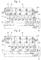
- Fig.1 is a schematic representation of a Monitoring device 1 with a safety circuit sensor system 2 and a motor and brake circuit 3 for an AC safety circuit 4 shown.
- the Safety circuit sensor 2 is for monitoring the Safety circuit 4, for example whether the Safety circuit 4 is open or closed.
- the motor and brake circuit 3 for it resulting follow-up actions in relation to a Drive motor 5 respectively.
- an associated brake 6 Im Safety circuit 4, the elevator car and shaft is looped, there are several contacts 7, for example on the landing doors, which are checked have to.
- a signal source 10 of the safety circuit 4 must be in the Frequency from the mains voltage (230V, 50 / 60Hz) distinguishable, for example 200Hz, and the voltage should be 24V (protection against contact).
- the safety circuit sensor system 2 deliver four output signals. Security against three Errors require the use of four sensors included Evaluation electronics. Because of the contact crosstalk capacity is between the heads of the safety circuit 4 Voltage measurement alone cannot determine whether the load / measuring resistor has an interruption. Therefore, the Voltage and current of the safety circuit 4 measured become. The current measurement must go through an element with energy transfer.
- the maximum possible current in the open Safety circuit 4 should be at least three times smaller than the minimum current in the closed safety circuit 4, in which a current sensor switches on. Desweitern should turn off a voltage sensor when the Phase shift from the source signal more than is sixty degrees.
- Optocouplers are used as current sensors 15 (or also transformers) with a defined Transfer factor used. So that a defined Current threshold can be determined is a Output transistor 16 fed with a current source. This will make for a negative and a positive Safety circuit current each generates a signal that subsequently filtered and in an evaluation unit 17 is processed digitally. These two signals are in the evaluation unit 17 with a Synchronization signal from a synchronization unit 18 linked. This can cause false signals, for example, the interference frequency 50 / 60Hz, at least are suppressed every half-period. Further includes the evaluation unit 17 of the current sensor 15 flip-flops, which generate a reset pulse for a counter if there is no valid signal in a half period would. In the absence of a synchronization signal, the However, flip-flops do not generate reset pulses. Out for this reason, a monitoring circuit sets the counter back if the synchronization signal is missing.
- the output signals are combined and put on one Led counter. With a defined meter reading a current sensor output 20 reaches a state 1, which means that safety circuit 4 is closed. At the same time, the counter input is blocked.
- the digital part of the evaluation unit 17 can also be used PAL, GAL, EPLD or ASIC can be realized.
- synchronization unit 18 Synchronization of the current sensors 15 and Voltage sensors 25 from the source signal Square wave generated.
- An operational amplifier is wired as a bandpass and ensures at the same time a level adjustment. Low and high signals Frequencies are suppressed.
- the voltage sensor 25 contains an operational amplifier which is wired the same way as in the Synchronization unit 18 and one Operational amplifier that inverts this signal. Analog switches transmit the signals from these two Operational amplifier piece by piece to an active, unbalanced filter (connected as active low pass Operational amplifier). The sensor input signal is correct coincide with the source signal, the Analog switch like a rectifier. If not Case, the sensor input signal is dismembered and by subsequent filter greatly weakened. A diode in front The low pass ensures that negative input signals amplified (approx. ten times) on a filter capacitor in Act in the direction of switching off. Another Operational amplifier is included as a threshold switch Hysteresis switches and supplies the signal on Voltage sensor output 26.
- the four output signals of the safety circuit sensors 2 the sensors described above and synchronization carried out twice.
- the Signal evaluation also implemented with digital sampling become.
- the circuit is based on the Voltage sensor described.
- the source signal becomes generates a scanning signal via synchronization, which for Time of the voltage maximum has the state 1. Lies at this time the voltage of the safety circuit 4 above a threshold, a count for one Counter generated. If this is not the case or does it fall If the scanning signal is off, the counter receives a reset pulse.
- FIG 2 is a schematic representation of a Monitoring device 30 for a direct current safety circuit 31 with a safety circuit sensor system 32 and a motor and brake circuit 33.
- Die Safety circuit sensor system 32 is for monitoring the Safety circuit 31 responsible, the engine and Brake circuit 33 for the resulting Follow-up actions with respect to a drive motor 34 respectively. an associated brake 35.
- the safety circuit 31 is looped through the elevator car and shaft several contacts 36, for example on the shaft doors, available that need to be checked.
- the safety circuit sensor system 32 is equipped with a DC-operated safety circuit 31 much easier than with alternating current, as already taken from Fig.2 can be.
- the synchronization with the source signal omitted and the evaluation only has to be carried out for one current / voltage direction will be realized.
- a signal source 40 of the safety circuit 31 is connected DC operated. Voltage and current in the Safety circuit 31 must be selected so that the Contacts 36 the material migration is negligibly small is. The voltage should continue for reasons of Protection against contact be less than 60V. From these For example, the voltage can be set to 48V (Protection against contact). The coupling of the Mains voltage in the safety circuit 31 forms the Operation with direct current continues to be a source of interference. The Filtering out this disturbance leads to the Response time of the evaluation circuit longer than the previous one AC safety circuit described.
- a current sensor 45 consists of an optocoupler Power supply as in the AC safety circuit above is described. It will be a signal generated, which is then in an evaluation unit 46 is filtered by 50 Hz interference signals to the mains voltage suppress and digitally processed. in the The structure of the evaluation unit 46 is essential identical to that of the AC safety circuit.
- a voltage threshold switch is used as the voltage sensor 47 with hysteresis and a subsequent one Filters used to supply 50Hz noise to the mains voltage suppress.
- the four output signals of the safety circuit sensors 32 are also available when operating with direct current the sensors described above are carried out twice.
- Safety circuit taps for diagnostic functions are also here how to build the voltage sensors 47.
- FIGS. 1 and 2 show a representation of the monitoring device 1, 30 with the motor and brake circuit 3, 33.
- the one in FIGS. 1 and 2 is also shown schematically described safety circuit 4, 31 with the signal source 10, 40, and the safety circuit sensors 2, 32 with the Connection to the motor and brake circuit 3, 33, respectively. with the current sensor outputs 20 and the voltage sensor outputs 26th
- the frequency converter power section 50 contains all of them Power electronics elements around the mains voltage in one DC link DC voltage and from it into three-phase current convert for the drive motor 5, 34.
- the VWF drive / control part 51 is the summary of the Components of drive control and elevator control.
- the VVVF drive / control part 51 controls the Frequency converter power section 50 and on the other hand from the intelligent protection system 52 as an interface addressed.
- the intelligent protection system 52 is that Safety module of the electric drive. It exists from an electronic safety circuit and monitors all safety-related functions. If the Safety circuit 4, 31 opens, activates the intelligent one Protection system 52 the brake 6, 35 and switches the Energy flow to the drive motor 5, 34 from. Put that intelligent protection system 52 found a malfunction the elevator is also stopped.
- the Brake control 53 contains all the switching elements to the Switch brake 6, 35 on and off safely. The Brake control 53 must be the highest Security requirements meet and is therefore direct and continuously from the intelligent protection system 52 checked.
- the interface between the VVVF drive / control part 51 and the intelligent protection system 52 is hereby very simple without electromechanical contactors.
- the three-phase energy flow to the drive motor 5, 34 can be blocked and released by the intelligent protection system 52 by means of two switching elements, an input rectifier 55 and an IGBT inverter 56, via a VVVF drive / control part 51.
- the input rectifier 55 which is fed by three phases L1, L2, L3, consists of half a thyristor bridge with rectifier control 57.
- the input rectifier 55 can be switched on and off by the rectifier control 57. When it is switched off, a small current flows through a charging resistor R c .
- Control signals T1 to T6 of a pulse width modulation PWM for controlling the IGBTs of the inverter 56 are checked and released as a block by the intelligent protection system 52 via a logic link in the VVVF drive / control part 51.
- Measurement signals of the motor current i U , i V , I w are preprocessed by the VVVF drive / control part 51 and passed on to the intelligent protection system 52.
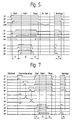
- the intelligent protection system 52 measures the time t2 switching off the brake magnet current. Exceed this Time a certain value, becomes an emergency stop initiated. This monitoring is imperative so it is ensured that all elements within one be checked once at a certain time.
- the Shutdown sequence is provided by the intelligent protection system 52 supervised.
- the Time t3 of the shutdown sequence is the intelligent Protection system 52 monitors.
- An emergency stop is initiated when the intelligent Protection system 52 detects a malfunction or the Safety circuit is interrupted.
- FIG. 6 shows a second variant of a motor control. Instead of the input rectifier 55, a Comprehensive circuit for regenerative power supply be used. Because of this, in this second variant a solution without monitoring the Input rectifier 55 described. The will continue IGBT's of the inverter 56 from the intelligent protection system 52 no longer as a block but in groups of two tested and approved.
- the switching means (IGBT) and the brake 6, 35 are through the intelligent protection system 52 locked. s2, s4, s6 and s8 are zero.
- the VVVF drive / control part 51 wants to drive kick off. Before the journey from the protection system 52 is released, the switching means must be checked. For this purpose, the VVVF drive / control part 51 generates the PWM signal for the transistors so they're for the test's can be switched on. The transistors can are not switched on statically for a long time, because the current in the motor winding is at a standstill would be big.
- the VVVF drive / control part divides 51 the protection system 52 with that T1 and T6 should be checked.
- the protection system 52 turns on s2.
- the currents iU and iW increase.
- the Protection system 52 measures the current and switches after one defined time s2 again, so that the current against Zero goes.
- the VVVF drive / control part 51 controls the Transistors to the holding torque in the drive motor 5, 34 to build.
- the intelligent protection system 52 measures the time t2 brake activation. If t2 exceeds a certain one Value, an emergency stop is initiated. This surveillance is imperative to ensure that everyone Elements checked once within a certain time become.
- the VVVF drive / control section regulates 51 the motor current towards zero and then switches off s1, s3 and s5.
- the protection system 52 also s2, s4 and s6. the time t3 the shutdown sequence is monitored by the protection system 52.
- An emergency stop is initiated when the protection system 52 detects a malfunction or the safety circuit is interrupted.
- the intelligent protection system 52 monitors that the time t3 has a certain value not exceed, otherwise using s2, s4 and s6 off.
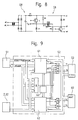
- Fig. 8 shows an embodiment of the brake control 53.
- the brake control 53 is responsible for the control the brake 6, 35. It must absolutely be prevented can that the braking current is no longer turned off can be. The elevator car could drift away, causing too can lead to a dangerous state. For this reason the brake voltage should be reduced as soon as the The armature of the MGB brake magnet is attracted. Before the Protection system 52 turns on the braking current through voltage measurement for all switching elements the switched off state is determined.
- the DC voltage for operating the brake 6, 34 can either with a rectifier GR, a transformer or with a switching power supply are generated. It has Switching power supply the advantage that the output voltage is on, off and switchable and a small tolerance having.
- the energy of the brake magnet MGB can be converted into heat when switched off, for example in a varistor R3, or fed back into a smoothing capacitor C G.
- the power can be reduced in this circuit by clocking a transistor. For example, if a transistor T T1 , T T2 is only switched on 50%, the brake magnet current flows through a free-wheeling diode D1, D2 during the pause. This halves the average braking voltage.
- the transistors T T1 , T T2 can be functionally tested by alternately briefly switching off the transistors. While the transistor is switched off, the current flows through the freewheeling diode D1, D2 in the same branch. When the brake 6, 34 is switched off, a small current flows through the resistors R1, R2. With the aid of the voltages u1, u2, u3 it can thus be checked by the protection system 52 whether the transistors T T1 , T T2 are short-circuited. The power in the brake 6, 34 can be controlled as desired by increasing the switch-off time.
- This relay is from intelligent protection system 52 controlled so that it is in Normal operation switches off. Only if one If the transistor is defective, the relay needs the braking current can switch off.
- the function check of this relay over the protection system 52 can by voltage measurement or by means of a positively driven break contact respectively.
- Fig. 9 shows a schematic representation of the intelligent protection system 52 with the associated Interfaces to safety circuit sensors 2, 32 for VVVF drive / control part 51, for brake control 53 and to a variant like the one described above necessary brake relay control 60.
- the in the functions described in the preceding figures and Processes of the intelligent protection system 52 are shown in Form of a program of microcontrollers 61, 62 two-channel controlled and monitored or processed. In a state comparator 63 is used to obtain specific data from the two microcontrollers 61, 62 compared with each other.
- the program detects errors in the switching process the safety circuit sensors 2, 32, the VVVF drive / control section 51, the frequency converter power section 50, the brake control 53 and the intelligent protection system 52 and prevents dangerous states of the elevator by locking the Motor current and by switching off the braking current.
Claims (7)
- Dispositif de surveillance (1, 30) pour une commande d'entraínement pour ascenseurs, le dispositif de surveillance (1, 30) surveillant un circuit de sécurité. (4, 31) muni de contacts (7, 36) qui est actionné par une source de signaux (10, 40) avec du courant continu ou du courant alternatif et déclenchant les actions consécutives qui en résultent, comme l'actionnement d'un frein (6, 35) ou la mise en circuit/hors circuit du courant d'un moteur (5, 34), le dispositif de surveillance (1, 30) étant composé d'un système de capteurs de circuit de sécurité (2, 32) et d'un circuit de commutation de moteur et/ou de frein (3, 33) qui sont en relation entre eux, caractérisé en ce que le dispositif de surveillance (1, 30) est exclusivement composé de composants électroniques.
- Dispositif de surveillance (1, 30) selon la revendication 1, caractérisé en ce que, lorsque le circuit de sécurité (4) fonctionne avec un courant continu, le systèmede capteurs de circuit de sécurité (2, 32) est composé au moins d'un capteur de courant (15) muni d'une unité d'analyse (17) et d'un capteur de tension (25).
- Dispositif de surveillance (1, 30) selon la revendication 1, caractérisé en ce que, lorsque le circuit de sécurité (4) fonctionne avec un courant alternatif, le système de capteurs de circuit de sécurité (2, 32) est composé au moins d'un capteur de courant (15) muni d'une unité d'analyse (17), d'une unité de synchronisation (18) et d'un capteur de tension (25).
- Dispositif de surveillance (1, 30) selon une des revendications 1 à 3, caractérisé en ce que le circuit de commutation de moteur et/ou de frein (3, 33) est essentiellement composé d'un élément de puissance convertisseur de fréquence (50), d'un élément d'entraínement VVVF (à tension et fréquence variables) de commande (51), d'un système de protection intelligent (52) et d'une commande de frein (53), le système de protection intelligent (52) assurant toutes les fonctions de surveillance et de commande relatives à la sécurité du système de capteurs de circuit de sécurité (2, 32), de l'élément d'entraínement VVVF/de commande (51), de l'élément de puissance convertisseur de fréquence (50) et de la commande de frein (53).
- Dispositif de surveillance (1, 30) selon une des revendications 1 à 4, caractérisé en ce que le système de protection intelligent (52) exécute les fonctions de surveillance et de commande relatives à la sécurité en deux canaux et présente un comparateur d'état (63) destiné à la comparaison des deux canaux.
- Dispositif de surveillance (1, 30) selon la revendication 5, caractérisé en ce que, pour chaque canal, il est prévu un micro contrôleur (61, 62) équipé d'un programme.
- Dispositif de surveillance (1, 30) selon la revendication 6, caractérisé en ce qu'il est prévu un programme qui détecte des défauts dans le déroulement des processus de commande du système de capteurs de circuit de sécurité (2, 32), de l'élément d'entraínement VVVF/de commande (51), de l'élément de puissance convertisseur de fréquence (50), de la commande de frein (53) et du système de protection intelligent (52), et empêche les états dangereux de l'ascenseur.
Priority Applications (1)
| Application Number | Priority Date | Filing Date | Title |
|---|---|---|---|
| EP98117235A EP0903314B1 (fr) | 1997-09-22 | 1998-09-11 | Dispositif de surveillance pour une commande de machinerie d'ascenseur |
Applications Claiming Priority (3)
| Application Number | Priority Date | Filing Date | Title |
|---|---|---|---|
| EP97810690 | 1997-09-22 | ||
| EP97810690 | 1997-09-22 | ||
| EP98117235A EP0903314B1 (fr) | 1997-09-22 | 1998-09-11 | Dispositif de surveillance pour une commande de machinerie d'ascenseur |
Publications (2)
| Publication Number | Publication Date |
|---|---|
| EP0903314A1 EP0903314A1 (fr) | 1999-03-24 |
| EP0903314B1 true EP0903314B1 (fr) | 2003-02-26 |
Family
ID=8230398
Family Applications (1)
| Application Number | Title | Priority Date | Filing Date |
|---|---|---|---|
| EP98117235A Expired - Lifetime EP0903314B1 (fr) | 1997-09-22 | 1998-09-11 | Dispositif de surveillance pour une commande de machinerie d'ascenseur |
Country Status (10)
| Country | Link |
|---|---|
| US (1) | US6056088A (fr) |
| EP (1) | EP0903314B1 (fr) |
| JP (1) | JP4295373B2 (fr) |
| AR (1) | AR017759A1 (fr) |
| AT (1) | ATE233226T1 (fr) |
| BR (1) | BR9803584B1 (fr) |
| CA (1) | CA2248335C (fr) |
| DE (1) | DE59807293D1 (fr) |
| ES (1) | ES2192724T3 (fr) |
| ZA (1) | ZA988339B (fr) |
Cited By (2)
| Publication number | Priority date | Publication date | Assignee | Title |
|---|---|---|---|---|
| DE102004006049A1 (de) * | 2004-01-30 | 2005-08-18 | Detlev Dipl.-Ing. Abraham | Verfahren und Anordnung zum Stillsetzen von Aufzügen |
| DE102015204400A1 (de) | 2014-12-09 | 2016-06-09 | Thyssenkrupp Ag | Ansteuereinrichtung für Bremsen |
Families Citing this family (42)
| Publication number | Priority date | Publication date | Assignee | Title |
|---|---|---|---|---|
| US6173814B1 (en) * | 1999-03-04 | 2001-01-16 | Otis Elevator Company | Electronic safety system for elevators having a dual redundant safety bus |
| SG87902A1 (en) * | 1999-10-01 | 2002-04-16 | Inventio Ag | Monitoring device for drive equipment for lifts |
| US6382362B1 (en) * | 2001-02-13 | 2002-05-07 | Inventio Ag | Optical monitoring system for hoistway door interlocks |
| DE10122204B4 (de) * | 2001-05-08 | 2008-10-09 | Otis Elevator Co., Farmington | Aufzugssicherheitssystem |
| US6778079B2 (en) * | 2001-05-16 | 2004-08-17 | Banner Engineering | Input/output methodology for control reliable interconnection of safety light curtains and other machine safety controls |
| FI20031647A0 (fi) * | 2003-11-12 | 2003-11-12 | Kone Corp | Hissin jarrun ohjauspiiri |
| JP4566992B2 (ja) * | 2004-02-26 | 2010-10-20 | 三菱電機株式会社 | エレベータ安全装置 |
| FI116937B (fi) * | 2004-11-01 | 2006-04-13 | Kone Corp | Hissin testijärjestelmä |
| DE502005001371D1 (de) * | 2005-01-07 | 2007-10-11 | Thyssen Krupp Aufzuege Gmbh | Aufzugsanlage mit einer Steuervorrichtung |
| FI117797B (fi) * | 2005-04-08 | 2007-02-28 | Kone Corp | Hissijärjestelmä |
| AT502582B1 (de) * | 2005-09-20 | 2008-05-15 | Tuev Oesterreich Tech Ueberwac | Überwachungseinrichtung einer aufzugsanlage |
| FI118642B (fi) * | 2006-04-28 | 2008-01-31 | Kone Corp | Hissijärjestelmä |
| FI119231B (fi) * | 2006-12-08 | 2008-09-15 | Kone Corp | Menetelmä, järjestelmä ja ohjelmistotuote hissin turvakytkinten kunnon seuraamiseksi |
| EP2341609B1 (fr) * | 2008-10-15 | 2018-05-02 | Panasonic Corporation | Dispositif de commande de moteur |
| JP5327867B2 (ja) * | 2009-09-18 | 2013-10-30 | 東芝エレベータ株式会社 | エレベータの安全制御装置 |
| KR101666251B1 (ko) * | 2009-10-26 | 2016-10-13 | 인벤티오 아게 | 엘리베이터 시스템의 안전 회로 |
| DE102010015312A1 (de) * | 2010-04-17 | 2011-10-20 | Audi Ag | Hochvoltsystem für ein Kraftfahrzeug und Verfahren zur Diagnose eines Hochvoltsystems für ein Kraftfahrzeug |
| US8970152B2 (en) | 2010-07-30 | 2015-03-03 | Otis Elevator Company | Elevator motor power supply control |
| FI122393B (fi) | 2010-10-11 | 2011-12-30 | Kone Corp | Menetelmä hissin hätäseis -tilanteen yhteydessä sekä hissin turvajärjestely |
| FI122474B (fi) * | 2010-12-01 | 2012-02-15 | Kone Corp | Hissin turvakytkentä sekä menetelmä hissin turvakytkennän toiminnallisen poikkeaman tunnistamiseksi |
| EP2460753A1 (fr) * | 2010-12-03 | 2012-06-06 | Inventio AG | Procédé d'essai des freins d'élévateurs |
| FI122473B (fi) | 2010-12-14 | 2012-02-15 | Kone Corp | Liitäntäyksikkö, kuljetusjärjestelmä sekä menetelmä |
| KR101304481B1 (ko) * | 2011-10-14 | 2013-09-05 | 티센크루프 아우프주크스베르케 게엠베하 | 엘리베이터 제어 장치 |
| FI123506B (fi) * | 2012-05-31 | 2013-06-14 | Kone Corp | Hissin käyttölaite sekä hissin turvajärjestely |
| WO2014003722A1 (fr) | 2012-06-26 | 2014-01-03 | Otis Elevator Company | Circuit de chaîne de sécurité |
| CN102795524B (zh) * | 2012-07-27 | 2014-07-23 | 石家庄五龙制动器股份有限公司 | 电梯制动系统的abs制动控制电路 |
| CA2898671C (fr) * | 2013-02-12 | 2020-08-18 | Inventio Ag | Surveillance de circuit de securite au moyen d'une tension alternative |
| EP2956394B1 (fr) * | 2013-02-14 | 2021-03-31 | Otis Elevator Company | Circuit de sécurité d'ascenseur |
| DE102013101932A1 (de) * | 2013-02-27 | 2014-08-28 | Pilz Gmbh & Co. Kg | Sicherheitsschaltvorrichtung zum Ein- und fehlersicheren Ausschalten einer technischen Anlage |
| KR101880830B1 (ko) * | 2013-09-27 | 2018-07-20 | 미쓰비시덴키 가부시키가이샤 | 엘리베이터의 제어 장치 |
| JP6015708B2 (ja) * | 2014-05-13 | 2016-10-26 | 株式会社デンソー | 3相回転機の電流制御システム |
| US10442660B2 (en) | 2014-09-12 | 2019-10-15 | Otis Elevator Company | Elevator brake control system |
| US10450162B2 (en) | 2015-06-29 | 2019-10-22 | Otis Elevator Company | Electromagnetic brake control circuitry for elevator application |
| AU2016307263B2 (en) * | 2015-08-12 | 2019-07-18 | Inventio Ag | Anti-lock braking arrangement for an elevator and method for controlling same |
| ES2714352T3 (es) * | 2015-10-07 | 2019-05-28 | Kone Corp | Unidad de conexión de sensor, sistema de seguridad y ascensor |
| EP3192760B1 (fr) * | 2016-01-13 | 2022-03-02 | KONE Corporation | Procédé pour tester le fonctionnement d'un ascenseur et ascenseur |
| CN106154949A (zh) * | 2016-07-28 | 2016-11-23 | 杭州巨骐信息科技股份有限公司 | 一种机房智能测控系统 |
| US10745244B2 (en) * | 2017-04-03 | 2020-08-18 | Otis Elevator Company | Method of automated testing for an elevator safety brake system and elevator brake testing system |
| US10680538B2 (en) | 2017-09-28 | 2020-06-09 | Otis Elevator Company | Emergency braking for a drive system |
| CN108394775B (zh) * | 2018-04-28 | 2020-04-14 | 苏州汇川技术有限公司 | 电梯安全系统及安全控制方法 |
| CN110482344A (zh) * | 2019-08-27 | 2019-11-22 | 山东奔速电梯股份有限公司 | 一种家用电梯及其保护控制方法 |
| CN113086802B (zh) * | 2021-03-30 | 2022-07-22 | 日立电梯(中国)有限公司 | 一种电梯安全回路电压诊断系统及方法 |
Family Cites Families (9)
| Publication number | Priority date | Publication date | Assignee | Title |
|---|---|---|---|---|
| BR7203809D0 (pt) * | 1972-06-14 | 1974-04-18 | A Podcameni | Sistema de seguranca para controle de partida de elevadores |
| GB2110388A (en) * | 1981-10-30 | 1983-06-15 | Yorkshire Chemicals Ltd | Improvements relating to electrical controls for lifts, hoists and the like |
| AT394022B (de) * | 1989-03-01 | 1992-01-27 | Tuma Oskar | Aufzugsanlage |
| US5107964A (en) * | 1990-05-07 | 1992-04-28 | Otis Elevator Company | Separate elevator door chain |
| JP2502167B2 (ja) * | 1990-05-24 | 1996-05-29 | 三菱電機株式会社 | エレベ―タの速度制御装置 |
| DE4112626A1 (de) * | 1991-04-18 | 1992-10-22 | Fraunhofer Ges Forschung | Ueberwachungseinrichtung fuer eine steuervorrichtung |
| CA2132152C (fr) * | 1993-10-06 | 2005-02-15 | Peter Spiess | Circuit de securite de porte, utilise pour surveiller les portes d'etage d'un ascenseur |
| US5635688A (en) * | 1994-10-31 | 1997-06-03 | Otis Elevator Company | Start jerk reduction for an elevator |
| DE69622655T2 (de) * | 1995-10-05 | 2003-04-03 | Otis Elevator Co | Fehlerdetektor für Aufzugsantrieb |
-
1998
- 1998-09-11 ES ES98117235T patent/ES2192724T3/es not_active Expired - Lifetime
- 1998-09-11 ZA ZA988339A patent/ZA988339B/xx unknown
- 1998-09-11 DE DE59807293T patent/DE59807293D1/de not_active Expired - Lifetime
- 1998-09-11 AT AT98117235T patent/ATE233226T1/de active
- 1998-09-11 EP EP98117235A patent/EP0903314B1/fr not_active Expired - Lifetime
- 1998-09-17 JP JP26287498A patent/JP4295373B2/ja not_active Expired - Fee Related
- 1998-09-21 US US09/158,020 patent/US6056088A/en not_active Expired - Fee Related
- 1998-09-22 CA CA002248335A patent/CA2248335C/fr not_active Expired - Fee Related
- 1998-09-22 BR BRPI9803584-3B1A patent/BR9803584B1/pt active IP Right Grant
- 1998-09-22 AR ARP980104729A patent/AR017759A1/es active IP Right Grant
Cited By (3)
| Publication number | Priority date | Publication date | Assignee | Title |
|---|---|---|---|---|
| DE102004006049A1 (de) * | 2004-01-30 | 2005-08-18 | Detlev Dipl.-Ing. Abraham | Verfahren und Anordnung zum Stillsetzen von Aufzügen |
| US7775327B2 (en) | 2004-01-30 | 2010-08-17 | Danfoss A/S | Method and system for stopping elevators using AC motors driven by static frequency converters |
| DE102015204400A1 (de) | 2014-12-09 | 2016-06-09 | Thyssenkrupp Ag | Ansteuereinrichtung für Bremsen |
Also Published As
| Publication number | Publication date |
|---|---|
| DE59807293D1 (de) | 2003-04-03 |
| AR017759A1 (es) | 2001-10-24 |
| JP4295373B2 (ja) | 2009-07-15 |
| US6056088A (en) | 2000-05-02 |
| CA2248335C (fr) | 2008-06-17 |
| ATE233226T1 (de) | 2003-03-15 |
| CA2248335A1 (fr) | 1999-03-22 |
| EP0903314A1 (fr) | 1999-03-24 |
| ZA988339B (en) | 1999-03-23 |
| ES2192724T3 (es) | 2003-10-16 |
| BR9803584B1 (pt) | 2013-11-12 |
| BR9803584A (pt) | 1999-10-19 |
| JPH11165963A (ja) | 1999-06-22 |
Similar Documents
| Publication | Publication Date | Title |
|---|---|---|
| EP0903314B1 (fr) | Dispositif de surveillance pour une commande de machinerie d'ascenseur | |
| EP2741993B1 (fr) | Procédé de test d'une installation d'ascenseur et un dispositif de surveillance destiné à l'exécution du procédé de test | |
| WO2017055420A1 (fr) | Procédé et dispositif de commande d'un système d'ascenseur | |
| WO2016096269A1 (fr) | Circuit de sécurité pour une installation d'ascenseur | |
| DE102019128441A1 (de) | Anordnung und Verfahren zur Überwachung einer elektrischen Sicherheitsverriegelung | |
| CH663497A5 (de) | Antriebsanordnung mit einer schutzeinrichtung fuer die leistungstransistoren eines umformers. | |
| DE2444455B2 (de) | Steuersystem für eine Brenneranlage | |
| WO2011061108A1 (fr) | Interrupteur d'une installation électrique | |
| EP1037354B1 (fr) | Procédé de fonctionnement de l'entraínement électromoteur d'une installation pour un ascenseur et ascenseur utilisant une telle méthode | |
| EP1182762B1 (fr) | Outil électrique et procédé pour son utilisation | |
| EP3853989A1 (fr) | Dispositif de commande conçu pour un onduleur, onduleur conçu pour une machine asynchrone, véhicule et procédé pour faire fonctionner un onduleur | |
| DE4421406A1 (de) | Einzelmotorischer Antrieb eines als permanentmagnetischer Läufer eines Axialfeldmotors ausgebildeten schaftlosen Spinnrotors und Verfahren zum Betreiben des einzelmotorischen Antriebes | |
| EP2709226B1 (fr) | Agencement de circuit ainsi que convertisseur de niveau et circuit comparateur pour l'agencement de circuit | |
| EP3704048A1 (fr) | Dispositif de surveillance de sécurité destiné à surveiller des états relatifs à la sécurité dans une installation de transport de personnes ainsi que procédé destiné à faire fonctionner ce dernier | |
| EP0924528A1 (fr) | Dispositif électronique pour détecter la défaillance de systèmes électriques | |
| DE10159639A1 (de) | Verfahren und Vorrichtung zur Aufrechterhaltung der Versorgungsspannung einer Stromrichterelektronik während einer Ankerkurzschlussbremsung einer stromrichtergespeisten Drehfeldmaschine | |
| WO2018077918A1 (fr) | Système d'ascenseur comportant un circuit de commutation muni d'un commutateur surveillé au moyen d'un signal de tension alternative | |
| EP0103182B1 (fr) | Dispositif pour la surveillance des valves électriques d'un convertisseur de courant alternatif | |
| DE3436776A1 (de) | Ueberwachungseinrichtung insbesondere fuer einen kollektorlosen gleichstrommotor | |
| WO2020182339A1 (fr) | Système d'entraînement, présentant un convertisseur et un onduleur pour l'alimentation d'un moteur électrique | |
| EP4121383B1 (fr) | Unité de commande pour système de levage | |
| EP1323661B1 (fr) | Procédé pour stopper un dispositif de transport pour personnes | |
| EP1088781B1 (fr) | Dispositif de surveillance pour système d'entrainement d'ascenseurs | |
| WO2016091842A1 (fr) | Dispositif de commande pour freins | |
| WO2022008590A1 (fr) | Technologie pour permettre l'actionnement d'un étage de puissance |
Legal Events
| Date | Code | Title | Description |
|---|---|---|---|
| PUAI | Public reference made under article 153(3) epc to a published international application that has entered the european phase |
Free format text: ORIGINAL CODE: 0009012 |
|
| AK | Designated contracting states |
Kind code of ref document: A1 Designated state(s): AT BE CH DE ES FR GB IT LI NL |
|
| AX | Request for extension of the european patent |
Free format text: AL;LT;LV;MK;RO;SI |
|
| 17P | Request for examination filed |
Effective date: 19990819 |
|
| AKX | Designation fees paid |
Free format text: AT BE CH DE ES FR GB IT LI NL |
|
| GRAG | Despatch of communication of intention to grant |
Free format text: ORIGINAL CODE: EPIDOS AGRA |
|
| 17Q | First examination report despatched |
Effective date: 20020503 |
|
| GRAG | Despatch of communication of intention to grant |
Free format text: ORIGINAL CODE: EPIDOS AGRA |
|
| GRAH | Despatch of communication of intention to grant a patent |
Free format text: ORIGINAL CODE: EPIDOS IGRA |
|
| GRAH | Despatch of communication of intention to grant a patent |
Free format text: ORIGINAL CODE: EPIDOS IGRA |
|
| GRAA | (expected) grant |
Free format text: ORIGINAL CODE: 0009210 |
|
| AK | Designated contracting states |
Designated state(s): AT BE CH DE ES FR GB IT LI NL |
|
| REG | Reference to a national code |
Ref country code: GB Ref legal event code: FG4D Free format text: NOT ENGLISH |
|
| REG | Reference to a national code |
Ref country code: CH Ref legal event code: EP |
|
| REF | Corresponds to: |
Ref document number: 59807293 Country of ref document: DE Date of ref document: 20030403 Kind code of ref document: P |
|
| GBT | Gb: translation of ep patent filed (gb section 77(6)(a)/1977) |
Effective date: 20030415 |
|
| ET | Fr: translation filed | ||
| REG | Reference to a national code |
Ref country code: ES Ref legal event code: FG2A Ref document number: 2192724 Country of ref document: ES Kind code of ref document: T3 |
|
| PLBE | No opposition filed within time limit |
Free format text: ORIGINAL CODE: 0009261 |
|
| STAA | Information on the status of an ep patent application or granted ep patent |
Free format text: STATUS: NO OPPOSITION FILED WITHIN TIME LIMIT |
|
| 26N | No opposition filed |
Effective date: 20031127 |
|
| PGFP | Annual fee paid to national office [announced via postgrant information from national office to epo] |
Ref country code: AT Payment date: 20120912 Year of fee payment: 15 |
|
| PGFP | Annual fee paid to national office [announced via postgrant information from national office to epo] |
Ref country code: CH Payment date: 20130930 Year of fee payment: 16 Ref country code: NL Payment date: 20130918 Year of fee payment: 16 |
|
| PGFP | Annual fee paid to national office [announced via postgrant information from national office to epo] |
Ref country code: BE Payment date: 20130919 Year of fee payment: 16 |
|
| REG | Reference to a national code |
Ref country code: AT Ref legal event code: MM01 Ref document number: 233226 Country of ref document: AT Kind code of ref document: T Effective date: 20130911 |
|
| PG25 | Lapsed in a contracting state [announced via postgrant information from national office to epo] |
Ref country code: AT Free format text: LAPSE BECAUSE OF NON-PAYMENT OF DUE FEES Effective date: 20130911 |
|
| REG | Reference to a national code |
Ref country code: CH Ref legal event code: PL |
|
| PG25 | Lapsed in a contracting state [announced via postgrant information from national office to epo] |
Ref country code: NL Free format text: LAPSE BECAUSE OF NON-PAYMENT OF DUE FEES Effective date: 20150401 Ref country code: BE Free format text: LAPSE BECAUSE OF NON-PAYMENT OF DUE FEES Effective date: 20140930 |
|
| PG25 | Lapsed in a contracting state [announced via postgrant information from national office to epo] |
Ref country code: CH Free format text: LAPSE BECAUSE OF NON-PAYMENT OF DUE FEES Effective date: 20140930 Ref country code: LI Free format text: LAPSE BECAUSE OF NON-PAYMENT OF DUE FEES Effective date: 20140930 |
|
| REG | Reference to a national code |
Ref country code: FR Ref legal event code: PLFP Year of fee payment: 19 |
|
| PGFP | Annual fee paid to national office [announced via postgrant information from national office to epo] |
Ref country code: GB Payment date: 20160920 Year of fee payment: 19 Ref country code: DE Payment date: 20160921 Year of fee payment: 19 |
|
| PGFP | Annual fee paid to national office [announced via postgrant information from national office to epo] |
Ref country code: FR Payment date: 20160921 Year of fee payment: 19 |
|
| PGFP | Annual fee paid to national office [announced via postgrant information from national office to epo] |
Ref country code: ES Payment date: 20160916 Year of fee payment: 19 |
|
| PGFP | Annual fee paid to national office [announced via postgrant information from national office to epo] |
Ref country code: IT Payment date: 20160922 Year of fee payment: 19 |
|
| REG | Reference to a national code |
Ref country code: DE Ref legal event code: R119 Ref document number: 59807293 Country of ref document: DE |
|
| GBPC | Gb: european patent ceased through non-payment of renewal fee |
Effective date: 20170911 |
|
| REG | Reference to a national code |
Ref country code: FR Ref legal event code: ST Effective date: 20180531 |
|
| PG25 | Lapsed in a contracting state [announced via postgrant information from national office to epo] |
Ref country code: DE Free format text: LAPSE BECAUSE OF NON-PAYMENT OF DUE FEES Effective date: 20180404 Ref country code: GB Free format text: LAPSE BECAUSE OF NON-PAYMENT OF DUE FEES Effective date: 20170911 |
|
| PG25 | Lapsed in a contracting state [announced via postgrant information from national office to epo] |
Ref country code: IT Free format text: LAPSE BECAUSE OF NON-PAYMENT OF DUE FEES Effective date: 20170911 Ref country code: FR Free format text: LAPSE BECAUSE OF NON-PAYMENT OF DUE FEES Effective date: 20171002 |
|
| REG | Reference to a national code |
Ref country code: ES Ref legal event code: FD2A Effective date: 20181019 |
|
| PG25 | Lapsed in a contracting state [announced via postgrant information from national office to epo] |
Ref country code: ES Free format text: LAPSE BECAUSE OF NON-PAYMENT OF DUE FEES Effective date: 20170912 |