EP0902797B1 - Durable, low surface energy compounds and articles, apparatuses, and methods for using the same - Google Patents
Durable, low surface energy compounds and articles, apparatuses, and methods for using the same Download PDFInfo
- Publication number
- EP0902797B1 EP0902797B1 EP97923453A EP97923453A EP0902797B1 EP 0902797 B1 EP0902797 B1 EP 0902797B1 EP 97923453 A EP97923453 A EP 97923453A EP 97923453 A EP97923453 A EP 97923453A EP 0902797 B1 EP0902797 B1 EP 0902797B1
- Authority
- EP
- European Patent Office
- Prior art keywords
- die
- group
- polymeric compound
- coating
- epoxy
- Prior art date
- Legal status (The legal status is an assumption and is not a legal conclusion. Google has not performed a legal analysis and makes no representation as to the accuracy of the status listed.)
- Expired - Lifetime
Links
- 238000000034 method Methods 0.000 title claims description 38
- 150000001875 compounds Chemical class 0.000 title claims description 15
- 239000000203 mixture Substances 0.000 claims description 108
- 238000000576 coating method Methods 0.000 claims description 80
- 239000011248 coating agent Substances 0.000 claims description 73
- 239000000178 monomer Substances 0.000 claims description 54
- 239000007788 liquid Substances 0.000 claims description 28
- 229920000642 polymer Polymers 0.000 claims description 23
- 230000008569 process Effects 0.000 claims description 23
- 125000004432 carbon atom Chemical group C* 0.000 claims description 22
- 229910000077 silane Inorganic materials 0.000 claims description 19
- 230000003381 solubilizing effect Effects 0.000 claims description 19
- 125000001931 aliphatic group Chemical group 0.000 claims description 16
- NIXOWILDQLNWCW-UHFFFAOYSA-M Acrylate Chemical compound [O-]C(=O)C=C NIXOWILDQLNWCW-UHFFFAOYSA-M 0.000 claims description 12
- BLRPTPMANUNPDV-UHFFFAOYSA-N Silane Chemical compound [SiH4] BLRPTPMANUNPDV-UHFFFAOYSA-N 0.000 claims description 11
- 125000005647 linker group Chemical group 0.000 claims description 10
- 230000005855 radiation Effects 0.000 claims description 10
- 239000003999 initiator Substances 0.000 claims description 9
- 239000012986 chain transfer agent Substances 0.000 claims description 7
- 229910052739 hydrogen Inorganic materials 0.000 claims description 7
- 125000002496 methyl group Chemical group [H]C([H])([H])* 0.000 claims description 7
- 125000004430 oxygen atom Chemical group O* 0.000 claims description 7
- 239000004593 Epoxy Substances 0.000 claims description 6
- 239000001257 hydrogen Substances 0.000 claims description 6
- 125000004435 hydrogen atom Chemical group [H]* 0.000 claims description 6
- 238000004519 manufacturing process Methods 0.000 claims description 6
- 238000007788 roughening Methods 0.000 claims description 6
- 125000006162 fluoroaliphatic group Chemical group 0.000 claims description 4
- 125000005842 heteroatom Chemical group 0.000 claims description 4
- 239000012442 inert solvent Substances 0.000 claims description 4
- 125000002252 acyl group Chemical group 0.000 claims description 3
- 125000004122 cyclic group Chemical group 0.000 claims description 3
- 229910052736 halogen Inorganic materials 0.000 claims description 3
- 150000002367 halogens Chemical group 0.000 claims description 3
- 238000010438 heat treatment Methods 0.000 claims description 2
- -1 polytetrafluoroethylene Polymers 0.000 description 52
- XEKOWRVHYACXOJ-UHFFFAOYSA-N Ethyl acetate Chemical compound CCOC(C)=O XEKOWRVHYACXOJ-UHFFFAOYSA-N 0.000 description 24
- 229920001343 polytetrafluoroethylene Polymers 0.000 description 23
- 239000004810 polytetrafluoroethylene Substances 0.000 description 23
- 239000000463 material Substances 0.000 description 17
- 239000003054 catalyst Substances 0.000 description 16
- IJGRMHOSHXDMSA-UHFFFAOYSA-N Atomic nitrogen Chemical compound N#N IJGRMHOSHXDMSA-UHFFFAOYSA-N 0.000 description 14
- 230000001588 bifunctional effect Effects 0.000 description 14
- 150000001252 acrylic acid derivatives Chemical class 0.000 description 11
- 239000011324 bead Substances 0.000 description 11
- 238000002360 preparation method Methods 0.000 description 11
- ZWEHNKRNPOVVGH-UHFFFAOYSA-N 2-Butanone Chemical compound CCC(C)=O ZWEHNKRNPOVVGH-UHFFFAOYSA-N 0.000 description 10
- 238000001125 extrusion Methods 0.000 description 10
- 150000002734 metacrylic acid derivatives Chemical class 0.000 description 10
- 238000005422 blasting Methods 0.000 description 9
- 229920001223 polyethylene glycol Polymers 0.000 description 9
- 239000002904 solvent Substances 0.000 description 9
- BPSIOYPQMFLKFR-UHFFFAOYSA-N trimethoxy-[3-(oxiran-2-ylmethoxy)propyl]silane Chemical compound CO[Si](OC)(OC)CCCOCC1CO1 BPSIOYPQMFLKFR-UHFFFAOYSA-N 0.000 description 9
- 125000000217 alkyl group Chemical group 0.000 description 8
- 238000013459 approach Methods 0.000 description 8
- 229910052731 fluorine Inorganic materials 0.000 description 8
- 239000002245 particle Substances 0.000 description 8
- 238000007767 slide coating Methods 0.000 description 8
- 125000001424 substituent group Chemical group 0.000 description 8
- 229910052757 nitrogen Inorganic materials 0.000 description 7
- 239000007787 solid Substances 0.000 description 7
- 229910001220 stainless steel Inorganic materials 0.000 description 7
- 239000000758 substrate Substances 0.000 description 7
- YCKRFDGAMUMZLT-UHFFFAOYSA-N Fluorine atom Chemical compound [F] YCKRFDGAMUMZLT-UHFFFAOYSA-N 0.000 description 6
- 238000006243 chemical reaction Methods 0.000 description 6
- 239000011737 fluorine Substances 0.000 description 6
- 125000002887 hydroxy group Chemical group [H]O* 0.000 description 6
- 230000037452 priming Effects 0.000 description 6
- 239000010935 stainless steel Substances 0.000 description 6
- 239000004094 surface-active agent Substances 0.000 description 6
- 238000011144 upstream manufacturing Methods 0.000 description 6
- 238000009736 wetting Methods 0.000 description 6
- RTZKZFJDLAIYFH-UHFFFAOYSA-N Diethyl ether Chemical compound CCOCC RTZKZFJDLAIYFH-UHFFFAOYSA-N 0.000 description 5
- 239000000843 powder Substances 0.000 description 5
- 239000000047 product Substances 0.000 description 5
- HBMJWWWQQXIZIP-UHFFFAOYSA-N silicon carbide Chemical compound [Si+]#[C-] HBMJWWWQQXIZIP-UHFFFAOYSA-N 0.000 description 5
- XLYOFNOQVPJJNP-UHFFFAOYSA-N water Substances O XLYOFNOQVPJJNP-UHFFFAOYSA-N 0.000 description 5
- OZAIFHULBGXAKX-UHFFFAOYSA-N 2-(2-cyanopropan-2-yldiazenyl)-2-methylpropanenitrile Chemical compound N#CC(C)(C)N=NC(C)(C)C#N OZAIFHULBGXAKX-UHFFFAOYSA-N 0.000 description 4
- 125000003903 2-propenyl group Chemical group [H]C([*])([H])C([H])=C([H])[H] 0.000 description 4
- CSCPPACGZOOCGX-UHFFFAOYSA-N Acetone Chemical compound CC(C)=O CSCPPACGZOOCGX-UHFFFAOYSA-N 0.000 description 4
- 230000008901 benefit Effects 0.000 description 4
- 125000003700 epoxy group Chemical group 0.000 description 4
- 125000001495 ethyl group Chemical group [H]C([H])([H])C([H])([H])* 0.000 description 4
- 238000009472 formulation Methods 0.000 description 4
- 229930195733 hydrocarbon Natural products 0.000 description 4
- OMIGHNLMNHATMP-UHFFFAOYSA-N 2-hydroxyethyl prop-2-enoate Chemical compound OCCOC(=O)C=C OMIGHNLMNHATMP-UHFFFAOYSA-N 0.000 description 3
- UHOVQNZJYSORNB-UHFFFAOYSA-N Benzene Chemical compound C1=CC=CC=C1 UHOVQNZJYSORNB-UHFFFAOYSA-N 0.000 description 3
- KFZMGEQAYNKOFK-UHFFFAOYSA-N Isopropanol Chemical compound CC(C)O KFZMGEQAYNKOFK-UHFFFAOYSA-N 0.000 description 3
- CERQOIWHTDAKMF-UHFFFAOYSA-M Methacrylate Chemical compound CC(=C)C([O-])=O CERQOIWHTDAKMF-UHFFFAOYSA-M 0.000 description 3
- ZMXDDKWLCZADIW-UHFFFAOYSA-N N,N-Dimethylformamide Chemical compound CN(C)C=O ZMXDDKWLCZADIW-UHFFFAOYSA-N 0.000 description 3
- 229920003171 Poly (ethylene oxide) Polymers 0.000 description 3
- 239000004820 Pressure-sensitive adhesive Substances 0.000 description 3
- YXFVVABEGXRONW-UHFFFAOYSA-N Toluene Chemical compound CC1=CC=CC=C1 YXFVVABEGXRONW-UHFFFAOYSA-N 0.000 description 3
- 238000005299 abrasion Methods 0.000 description 3
- 125000003118 aryl group Chemical group 0.000 description 3
- 125000000484 butyl group Chemical group [H]C([*])([H])C([H])([H])C([H])([H])C([H])([H])[H] 0.000 description 3
- 150000001768 cations Chemical class 0.000 description 3
- 230000008859 change Effects 0.000 description 3
- 239000012530 fluid Substances 0.000 description 3
- 125000000524 functional group Chemical group 0.000 description 3
- 230000007246 mechanism Effects 0.000 description 3
- 229910052751 metal Inorganic materials 0.000 description 3
- 239000002184 metal Substances 0.000 description 3
- VLKZOEOYAKHREP-UHFFFAOYSA-N n-Hexane Chemical compound CCCCCC VLKZOEOYAKHREP-UHFFFAOYSA-N 0.000 description 3
- 125000000962 organic group Chemical group 0.000 description 3
- 230000000737 periodic effect Effects 0.000 description 3
- 238000007348 radical reaction Methods 0.000 description 3
- 239000000376 reactant Substances 0.000 description 3
- 239000011347 resin Substances 0.000 description 3
- 229920005989 resin Polymers 0.000 description 3
- 150000003839 salts Chemical class 0.000 description 3
- 125000004079 stearyl group Chemical group [H]C([*])([H])C([H])([H])C([H])([H])C([H])([H])C([H])([H])C([H])([H])C([H])([H])C([H])([H])C([H])([H])C([H])([H])C([H])([H])C([H])([H])C([H])([H])C([H])([H])C([H])([H])C([H])([H])C([H])([H])C([H])([H])[H] 0.000 description 3
- 125000000999 tert-butyl group Chemical group [H]C([H])([H])C(*)(C([H])([H])[H])C([H])([H])[H] 0.000 description 3
- 150000003573 thiols Chemical class 0.000 description 3
- 229910052724 xenon Inorganic materials 0.000 description 3
- FHNFHKCVQCLJFQ-UHFFFAOYSA-N xenon atom Chemical compound [Xe] FHNFHKCVQCLJFQ-UHFFFAOYSA-N 0.000 description 3
- 229920002818 (Hydroxyethyl)methacrylate Polymers 0.000 description 2
- SMZOUWXMTYCWNB-UHFFFAOYSA-N 2-(2-methoxy-5-methylphenyl)ethanamine Chemical class COC1=CC=C(C)C=C1CCN SMZOUWXMTYCWNB-UHFFFAOYSA-N 0.000 description 2
- NIXOWILDQLNWCW-UHFFFAOYSA-N 2-Propenoic acid Chemical class OC(=O)C=C NIXOWILDQLNWCW-UHFFFAOYSA-N 0.000 description 2
- JMADMUIDBVATJT-UHFFFAOYSA-N 2-methylprop-2-enamide;propan-2-one Chemical compound CC(C)=O.CC(C)=O.CC(=C)C(N)=O JMADMUIDBVATJT-UHFFFAOYSA-N 0.000 description 2
- FIHBHSQYSYVZQE-UHFFFAOYSA-N 6-prop-2-enoyloxyhexyl prop-2-enoate Chemical compound C=CC(=O)OCCCCCCOC(=O)C=C FIHBHSQYSYVZQE-UHFFFAOYSA-N 0.000 description 2
- HGINCPLSRVDWNT-UHFFFAOYSA-N Acrolein Chemical compound C=CC=O HGINCPLSRVDWNT-UHFFFAOYSA-N 0.000 description 2
- 239000004215 Carbon black (E152) Substances 0.000 description 2
- VEXZGXHMUGYJMC-UHFFFAOYSA-M Chloride anion Chemical compound [Cl-] VEXZGXHMUGYJMC-UHFFFAOYSA-M 0.000 description 2
- 241000870659 Crassula perfoliata var. minor Species 0.000 description 2
- IAZDPXIOMUYVGZ-UHFFFAOYSA-N Dimethylsulphoxide Chemical compound CS(C)=O IAZDPXIOMUYVGZ-UHFFFAOYSA-N 0.000 description 2
- LFQSCWFLJHTTHZ-UHFFFAOYSA-N Ethanol Chemical compound CCO LFQSCWFLJHTTHZ-UHFFFAOYSA-N 0.000 description 2
- WSFSSNUMVMOOMR-UHFFFAOYSA-N Formaldehyde Chemical compound O=C WSFSSNUMVMOOMR-UHFFFAOYSA-N 0.000 description 2
- UFHFLCQGNIYNRP-UHFFFAOYSA-N Hydrogen Chemical compound [H][H] UFHFLCQGNIYNRP-UHFFFAOYSA-N 0.000 description 2
- WOBHKFSMXKNTIM-UHFFFAOYSA-N Hydroxyethyl methacrylate Chemical compound CC(=C)C(=O)OCCO WOBHKFSMXKNTIM-UHFFFAOYSA-N 0.000 description 2
- IMNFDUFMRHMDMM-UHFFFAOYSA-N N-Heptane Chemical compound CCCCCCC IMNFDUFMRHMDMM-UHFFFAOYSA-N 0.000 description 2
- PXHVJJICTQNCMI-UHFFFAOYSA-N Nickel Chemical compound [Ni] PXHVJJICTQNCMI-UHFFFAOYSA-N 0.000 description 2
- 239000004698 Polyethylene Substances 0.000 description 2
- QYKIQEUNHZKYBP-UHFFFAOYSA-N Vinyl ether Chemical class C=COC=C QYKIQEUNHZKYBP-UHFFFAOYSA-N 0.000 description 2
- 239000002253 acid Substances 0.000 description 2
- 230000002411 adverse Effects 0.000 description 2
- 150000001336 alkenes Chemical class 0.000 description 2
- 125000005250 alkyl acrylate group Chemical group 0.000 description 2
- 239000012298 atmosphere Substances 0.000 description 2
- 230000015572 biosynthetic process Effects 0.000 description 2
- 239000007795 chemical reaction product Substances 0.000 description 2
- 239000003795 chemical substances by application Substances 0.000 description 2
- 230000000052 comparative effect Effects 0.000 description 2
- RWGFKTVRMDUZSP-UHFFFAOYSA-N cumene Chemical compound CC(C)C1=CC=CC=C1 RWGFKTVRMDUZSP-UHFFFAOYSA-N 0.000 description 2
- 125000006165 cyclic alkyl group Chemical group 0.000 description 2
- 125000000113 cyclohexyl group Chemical group [H]C1([H])C([H])([H])C([H])([H])C([H])(*)C([H])([H])C1([H])[H] 0.000 description 2
- 230000007547 defect Effects 0.000 description 2
- 239000006185 dispersion Substances 0.000 description 2
- 239000000839 emulsion Substances 0.000 description 2
- 150000002148 esters Chemical class 0.000 description 2
- DNJIEGIFACGWOD-UHFFFAOYSA-N ethanethiol Chemical compound CCS DNJIEGIFACGWOD-UHFFFAOYSA-N 0.000 description 2
- 150000002170 ethers Chemical class 0.000 description 2
- 229940052303 ethers for general anesthesia Drugs 0.000 description 2
- 125000000816 ethylene group Chemical group [H]C([H])([*:1])C([H])([H])[*:2] 0.000 description 2
- 239000000835 fiber Substances 0.000 description 2
- 239000007789 gas Substances 0.000 description 2
- LEQAOMBKQFMDFZ-UHFFFAOYSA-N glyoxal Chemical compound O=CC=O LEQAOMBKQFMDFZ-UHFFFAOYSA-N 0.000 description 2
- 125000000555 isopropenyl group Chemical group [H]\C([H])=C(\*)C([H])([H])[H] 0.000 description 2
- 125000001449 isopropyl group Chemical group [H]C([H])([H])C([H])(*)C([H])([H])[H] 0.000 description 2
- 150000002576 ketones Chemical class 0.000 description 2
- FQPSGWSUVKBHSU-UHFFFAOYSA-N methacrylamide Chemical class CC(=C)C(N)=O FQPSGWSUVKBHSU-UHFFFAOYSA-N 0.000 description 2
- 238000002156 mixing Methods 0.000 description 2
- OMNKZBIFPJNNIO-UHFFFAOYSA-N n-(2-methyl-4-oxopentan-2-yl)prop-2-enamide Chemical compound CC(=O)CC(C)(C)NC(=O)C=C OMNKZBIFPJNNIO-UHFFFAOYSA-N 0.000 description 2
- TVMXDCGIABBOFY-UHFFFAOYSA-N octane Chemical compound CCCCCCCC TVMXDCGIABBOFY-UHFFFAOYSA-N 0.000 description 2
- KZCOBXFFBQJQHH-UHFFFAOYSA-N octane-1-thiol Chemical compound CCCCCCCCS KZCOBXFFBQJQHH-UHFFFAOYSA-N 0.000 description 2
- 125000005740 oxycarbonyl group Chemical group [*:1]OC([*:2])=O 0.000 description 2
- 125000001997 phenyl group Chemical group [H]C1=C([H])C([H])=C(*)C([H])=C1[H] 0.000 description 2
- 238000005498 polishing Methods 0.000 description 2
- 229920000573 polyethylene Polymers 0.000 description 2
- 238000006116 polymerization reaction Methods 0.000 description 2
- SUVIGLJNEAMWEG-UHFFFAOYSA-N propane-1-thiol Chemical compound CCCS SUVIGLJNEAMWEG-UHFFFAOYSA-N 0.000 description 2
- 125000001436 propyl group Chemical group [H]C([*])([H])C([H])([H])C([H])([H])[H] 0.000 description 2
- 150000004756 silanes Chemical class 0.000 description 2
- 239000000126 substance Substances 0.000 description 2
- 238000012360 testing method Methods 0.000 description 2
- 238000012546 transfer Methods 0.000 description 2
- 125000000391 vinyl group Chemical group [H]C([*])=C([H])[H] 0.000 description 2
- 229920002554 vinyl polymer Polymers 0.000 description 2
- QNODIIQQMGDSEF-UHFFFAOYSA-N (1-hydroxycyclohexyl)-phenylmethanone Chemical compound C=1C=CC=CC=1C(=O)C1(O)CCCCC1 QNODIIQQMGDSEF-UHFFFAOYSA-N 0.000 description 1
- DDKMFQGAZVMXQV-UHFFFAOYSA-N (3-chloro-2-hydroxypropyl) 2-methylprop-2-enoate Chemical compound CC(=C)C(=O)OCC(O)CCl DDKMFQGAZVMXQV-UHFFFAOYSA-N 0.000 description 1
- POTYORUTRLSAGZ-UHFFFAOYSA-N (3-chloro-2-hydroxypropyl) prop-2-enoate Chemical compound ClCC(O)COC(=O)C=C POTYORUTRLSAGZ-UHFFFAOYSA-N 0.000 description 1
- REMAVXPZIWANOX-UHFFFAOYSA-M (4-cyanophenyl)-diphenylsulfanium;iodide Chemical compound [I-].C1=CC(C#N)=CC=C1[S+](C=1C=CC=CC=1)C1=CC=CC=C1 REMAVXPZIWANOX-UHFFFAOYSA-M 0.000 description 1
- DELJOESCKJGFML-DUXPYHPUSA-N (e)-3-aminobut-2-enenitrile Chemical compound C\C(N)=C/C#N DELJOESCKJGFML-DUXPYHPUSA-N 0.000 description 1
- GETTZEONDQJALK-UHFFFAOYSA-N (trifluoromethyl)benzene Chemical compound FC(F)(F)C1=CC=CC=C1 GETTZEONDQJALK-UHFFFAOYSA-N 0.000 description 1
- BSSNZUFKXJJCBG-UPHRSURJSA-N (z)-but-2-enediamide Chemical compound NC(=O)\C=C/C(N)=O BSSNZUFKXJJCBG-UPHRSURJSA-N 0.000 description 1
- UOCLXMDMGBRAIB-UHFFFAOYSA-N 1,1,1-trichloroethane Chemical compound CC(Cl)(Cl)Cl UOCLXMDMGBRAIB-UHFFFAOYSA-N 0.000 description 1
- OXFSTTJBVAAALW-UHFFFAOYSA-N 1,3-dihydroimidazole-2-thione Chemical compound SC1=NC=CN1 OXFSTTJBVAAALW-UHFFFAOYSA-N 0.000 description 1
- 239000012956 1-hydroxycyclohexylphenyl-ketone Substances 0.000 description 1
- KWKAKUADMBZCLK-UHFFFAOYSA-N 1-octene Chemical group CCCCCCC=C KWKAKUADMBZCLK-UHFFFAOYSA-N 0.000 description 1
- FCBZNZYQLJTCKR-UHFFFAOYSA-N 1-prop-2-enoxyethanol Chemical class CC(O)OCC=C FCBZNZYQLJTCKR-UHFFFAOYSA-N 0.000 description 1
- LBEQDSMTGNIUIB-UHFFFAOYSA-M 2,2,2-trichloroacetate;triphenylsulfanium Chemical compound [O-]C(=O)C(Cl)(Cl)Cl.C1=CC=CC=C1[S+](C=1C=CC=CC=1)C1=CC=CC=C1 LBEQDSMTGNIUIB-UHFFFAOYSA-M 0.000 description 1
- YAJYJWXEWKRTPO-UHFFFAOYSA-N 2,3,3,4,4,5-hexamethylhexane-2-thiol Chemical compound CC(C)C(C)(C)C(C)(C)C(C)(C)S YAJYJWXEWKRTPO-UHFFFAOYSA-N 0.000 description 1
- STMDPCBYJCIZOD-UHFFFAOYSA-N 2-(2,4-dinitroanilino)-4-methylpentanoic acid Chemical compound CC(C)CC(C(O)=O)NC1=CC=C([N+]([O-])=O)C=C1[N+]([O-])=O STMDPCBYJCIZOD-UHFFFAOYSA-N 0.000 description 1
- CNDCQWGRLNGNNO-UHFFFAOYSA-N 2-(2-sulfanylethoxy)ethanethiol Chemical compound SCCOCCS CNDCQWGRLNGNNO-UHFFFAOYSA-N 0.000 description 1
- XNWFRZJHXBZDAG-UHFFFAOYSA-N 2-METHOXYETHANOL Chemical compound COCCO XNWFRZJHXBZDAG-UHFFFAOYSA-N 0.000 description 1
- XHZPRMZZQOIPDS-UHFFFAOYSA-N 2-Methyl-2-[(1-oxo-2-propenyl)amino]-1-propanesulfonic acid Chemical compound OS(=O)(=O)CC(C)(C)NC(=O)C=C XHZPRMZZQOIPDS-UHFFFAOYSA-N 0.000 description 1
- VETIYACESIPJSO-UHFFFAOYSA-N 2-[2-(2-hydroxyethoxy)ethoxy]ethyl prop-2-enoate Chemical compound OCCOCCOCCOC(=O)C=C VETIYACESIPJSO-UHFFFAOYSA-N 0.000 description 1
- QIRNGVVZBINFMX-UHFFFAOYSA-N 2-allylphenol Chemical class OC1=CC=CC=C1CC=C QIRNGVVZBINFMX-UHFFFAOYSA-N 0.000 description 1
- XRXANEMIFVRKLN-UHFFFAOYSA-N 2-hydroperoxy-2-methylbutane Chemical compound CCC(C)(C)OO XRXANEMIFVRKLN-UHFFFAOYSA-N 0.000 description 1
- RLLJBUZYAVNFOG-UHFFFAOYSA-N 2-methylprop-1-ene-1,1-diol Chemical class CC(C)=C(O)O RLLJBUZYAVNFOG-UHFFFAOYSA-N 0.000 description 1
- RUMACXVDVNRZJZ-UHFFFAOYSA-N 2-methylpropyl 2-methylprop-2-enoate Chemical compound CC(C)COC(=O)C(C)=C RUMACXVDVNRZJZ-UHFFFAOYSA-N 0.000 description 1
- DMQYPVOQAARSNF-UHFFFAOYSA-N 3-[2,3-bis(3-prop-2-enoyloxypropoxy)propoxy]propyl prop-2-enoate Chemical compound C=CC(=O)OCCCOCC(OCCCOC(=O)C=C)COCCCOC(=O)C=C DMQYPVOQAARSNF-UHFFFAOYSA-N 0.000 description 1
- GNSFRPWPOGYVLO-UHFFFAOYSA-N 3-hydroxypropyl 2-methylprop-2-enoate Chemical compound CC(=C)C(=O)OCCCO GNSFRPWPOGYVLO-UHFFFAOYSA-N 0.000 description 1
- QZPSOSOOLFHYRR-UHFFFAOYSA-N 3-hydroxypropyl prop-2-enoate Chemical compound OCCCOC(=O)C=C QZPSOSOOLFHYRR-UHFFFAOYSA-N 0.000 description 1
- PAKCOSURAUIXFG-UHFFFAOYSA-N 3-prop-2-enoxypropane-1,2-diol Chemical class OCC(O)COCC=C PAKCOSURAUIXFG-UHFFFAOYSA-N 0.000 description 1
- MAGFQRLKWCCTQJ-UHFFFAOYSA-N 4-ethenylbenzenesulfonic acid Chemical class OS(=O)(=O)C1=CC=C(C=C)C=C1 MAGFQRLKWCCTQJ-UHFFFAOYSA-N 0.000 description 1
- DXPPIEDUBFUSEZ-UHFFFAOYSA-N 6-methylheptyl prop-2-enoate Chemical compound CC(C)CCCCCOC(=O)C=C DXPPIEDUBFUSEZ-UHFFFAOYSA-N 0.000 description 1
- HRPVXLWXLXDGHG-UHFFFAOYSA-N Acrylamide Chemical compound NC(=O)C=C HRPVXLWXLXDGHG-UHFFFAOYSA-N 0.000 description 1
- 239000004342 Benzoyl peroxide Substances 0.000 description 1
- OMPJBNCRMGITSC-UHFFFAOYSA-N Benzoylperoxide Chemical compound C=1C=CC=CC=1C(=O)OOC(=O)C1=CC=CC=C1 OMPJBNCRMGITSC-UHFFFAOYSA-N 0.000 description 1
- 239000007848 Bronsted acid Substances 0.000 description 1
- DKPFZGUDAPQIHT-UHFFFAOYSA-N Butyl acetate Natural products CCCCOC(C)=O DKPFZGUDAPQIHT-UHFFFAOYSA-N 0.000 description 1
- GPVWCCOYPOFOKI-UHFFFAOYSA-N CCOC(C1=C(C2(C=CC=CC2)I)C2=CC=CC=C2C=C1)=O.Cl Chemical compound CCOC(C1=C(C2(C=CC=CC2)I)C2=CC=CC=C2C=C1)=O.Cl GPVWCCOYPOFOKI-UHFFFAOYSA-N 0.000 description 1
- XDTMQSROBMDMFD-UHFFFAOYSA-N Cyclohexane Chemical compound C1CCCCC1 XDTMQSROBMDMFD-UHFFFAOYSA-N 0.000 description 1
- ZAFNJMIOTHYJRJ-UHFFFAOYSA-N Diisopropyl ether Chemical compound CC(C)OC(C)C ZAFNJMIOTHYJRJ-UHFFFAOYSA-N 0.000 description 1
- XTHFKEDIFFGKHM-UHFFFAOYSA-N Dimethoxyethane Chemical compound COCCOC XTHFKEDIFFGKHM-UHFFFAOYSA-N 0.000 description 1
- 229920005682 EO-PO block copolymer Polymers 0.000 description 1
- YIVJZNGAASQVEM-UHFFFAOYSA-N Lauroyl peroxide Chemical compound CCCCCCCCCCCC(=O)OOC(=O)CCCCCCCCCCC YIVJZNGAASQVEM-UHFFFAOYSA-N 0.000 description 1
- 239000002841 Lewis acid Substances 0.000 description 1
- PEEHTFAAVSWFBL-UHFFFAOYSA-N Maleimide Chemical compound O=C1NC(=O)C=C1 PEEHTFAAVSWFBL-UHFFFAOYSA-N 0.000 description 1
- CERQOIWHTDAKMF-UHFFFAOYSA-N Methacrylic acid Chemical class CC(=C)C(O)=O CERQOIWHTDAKMF-UHFFFAOYSA-N 0.000 description 1
- NTIZESTWPVYFNL-UHFFFAOYSA-N Methyl isobutyl ketone Chemical compound CC(C)CC(C)=O NTIZESTWPVYFNL-UHFFFAOYSA-N 0.000 description 1
- UIHCLUNTQKBZGK-UHFFFAOYSA-N Methyl isobutyl ketone Natural products CCC(C)C(C)=O UIHCLUNTQKBZGK-UHFFFAOYSA-N 0.000 description 1
- FXHOOIRPVKKKFG-UHFFFAOYSA-N N,N-Dimethylacetamide Chemical compound CN(C)C(C)=O FXHOOIRPVKKKFG-UHFFFAOYSA-N 0.000 description 1
- CNCOEDDPFOAUMB-UHFFFAOYSA-N N-Methylolacrylamide Chemical compound OCNC(=O)C=C CNCOEDDPFOAUMB-UHFFFAOYSA-N 0.000 description 1
- YKRZVAFAUGJTRE-UHFFFAOYSA-N N=NS(=O)=O Chemical compound N=NS(=O)=O YKRZVAFAUGJTRE-UHFFFAOYSA-N 0.000 description 1
- CTQNGGLPUBDAKN-UHFFFAOYSA-N O-Xylene Chemical compound CC1=CC=CC=C1C CTQNGGLPUBDAKN-UHFFFAOYSA-N 0.000 description 1
- 239000002202 Polyethylene glycol Substances 0.000 description 1
- XUIMIQQOPSSXEZ-UHFFFAOYSA-N Silicon Chemical group [Si] XUIMIQQOPSSXEZ-UHFFFAOYSA-N 0.000 description 1
- 229910000831 Steel Inorganic materials 0.000 description 1
- XSTXAVWGXDQKEL-UHFFFAOYSA-N Trichloroethylene Chemical group ClC=C(Cl)Cl XSTXAVWGXDQKEL-UHFFFAOYSA-N 0.000 description 1
- FBNNUGJSOUOKEU-UHFFFAOYSA-M [Cl-].[Br+](c1ccccc1)c1ccccc1 Chemical compound [Cl-].[Br+](c1ccccc1)c1ccccc1 FBNNUGJSOUOKEU-UHFFFAOYSA-M 0.000 description 1
- 125000002777 acetyl group Chemical group [H]C([H])([H])C(*)=O 0.000 description 1
- 150000007513 acids Chemical class 0.000 description 1
- 150000003926 acrylamides Chemical class 0.000 description 1
- 150000001253 acrylic acids Chemical class 0.000 description 1
- 239000004480 active ingredient Substances 0.000 description 1
- 239000000853 adhesive Substances 0.000 description 1
- 230000001070 adhesive effect Effects 0.000 description 1
- 230000032683 aging Effects 0.000 description 1
- 150000001298 alcohols Chemical class 0.000 description 1
- 125000003545 alkoxy group Chemical group 0.000 description 1
- 125000004414 alkyl thio group Chemical group 0.000 description 1
- 150000001356 alkyl thiols Chemical group 0.000 description 1
- 125000002947 alkylene group Chemical group 0.000 description 1
- 125000006365 alkylene oxy carbonyl group Chemical group 0.000 description 1
- 150000001408 amides Chemical class 0.000 description 1
- 239000003849 aromatic solvent Substances 0.000 description 1
- 125000000732 arylene group Chemical group 0.000 description 1
- QVGXLLKOCUKJST-UHFFFAOYSA-N atomic oxygen Chemical compound [O] QVGXLLKOCUKJST-UHFFFAOYSA-N 0.000 description 1
- 235000019400 benzoyl peroxide Nutrition 0.000 description 1
- KYLDDEXSDLYMHS-UHFFFAOYSA-N benzyl-(2-nitrophenyl)sulfanium sulfate Chemical compound S(=O)(=O)([O-])[O-].[N+](=O)([O-])C1=C(C=CC=C1)[SH+]CC1=CC=CC=C1.[N+](=O)([O-])C1=C(C=CC=C1)[SH+]CC1=CC=CC=C1 KYLDDEXSDLYMHS-UHFFFAOYSA-N 0.000 description 1
- INONVDCAECLNMK-UHFFFAOYSA-M bis(4-methoxyphenyl)iodanium;chloride Chemical compound [Cl-].C1=CC(OC)=CC=C1[I+]C1=CC=C(OC)C=C1 INONVDCAECLNMK-UHFFFAOYSA-M 0.000 description 1
- MQDJYUACMFCOFT-UHFFFAOYSA-N bis[2-(1-hydroxycyclohexyl)phenyl]methanone Chemical compound C=1C=CC=C(C(=O)C=2C(=CC=CC=2)C2(O)CCCCC2)C=1C1(O)CCCCC1 MQDJYUACMFCOFT-UHFFFAOYSA-N 0.000 description 1
- 229920001400 block copolymer Polymers 0.000 description 1
- 229910052794 bromium Inorganic materials 0.000 description 1
- 230000001680 brushing effect Effects 0.000 description 1
- WQAQPCDUOCURKW-UHFFFAOYSA-N butanethiol Chemical compound CCCCS WQAQPCDUOCURKW-UHFFFAOYSA-N 0.000 description 1
- 125000005518 carboxamido group Chemical group 0.000 description 1
- 125000004181 carboxyalkyl group Chemical group 0.000 description 1
- 230000001413 cellular effect Effects 0.000 description 1
- 235000013351 cheese Nutrition 0.000 description 1
- 238000003486 chemical etching Methods 0.000 description 1
- 239000003153 chemical reaction reagent Substances 0.000 description 1
- 239000013626 chemical specie Substances 0.000 description 1
- 229910052801 chlorine Inorganic materials 0.000 description 1
- AFYPFACVUDMOHA-UHFFFAOYSA-N chlorotrifluoromethane Chemical compound FC(F)(F)Cl AFYPFACVUDMOHA-UHFFFAOYSA-N 0.000 description 1
- 238000004140 cleaning Methods 0.000 description 1
- 239000002131 composite material Substances 0.000 description 1
- 239000000805 composite resin Substances 0.000 description 1
- 238000010276 construction Methods 0.000 description 1
- 238000007334 copolymerization reaction Methods 0.000 description 1
- 238000005520 cutting process Methods 0.000 description 1
- LSXWFXONGKSEMY-UHFFFAOYSA-N di-tert-butyl peroxide Chemical compound CC(C)(C)OOC(C)(C)C LSXWFXONGKSEMY-UHFFFAOYSA-N 0.000 description 1
- 125000004386 diacrylate group Chemical group 0.000 description 1
- 239000012933 diacyl peroxide Substances 0.000 description 1
- 239000012954 diazonium Substances 0.000 description 1
- 150000001989 diazonium salts Chemical class 0.000 description 1
- 229960004132 diethyl ether Drugs 0.000 description 1
- SBZXBUIDTXKZTM-UHFFFAOYSA-N diglyme Chemical compound COCCOCCOC SBZXBUIDTXKZTM-UHFFFAOYSA-N 0.000 description 1
- 150000002009 diols Chemical class 0.000 description 1
- SMSLTJMQFBHKSO-UHFFFAOYSA-M diphenyliodanium;2,2,2-trichloroacetate Chemical compound [O-]C(=O)C(Cl)(Cl)Cl.C=1C=CC=CC=1[I+]C1=CC=CC=C1 SMSLTJMQFBHKSO-UHFFFAOYSA-M 0.000 description 1
- RSJLWBUYLGJOBD-UHFFFAOYSA-M diphenyliodanium;chloride Chemical compound [Cl-].C=1C=CC=CC=1[I+]C1=CC=CC=C1 RSJLWBUYLGJOBD-UHFFFAOYSA-M 0.000 description 1
- WQIRVUAXANLUPO-UHFFFAOYSA-M diphenyliodanium;iodide Chemical compound [I-].C=1C=CC=CC=1[I+]C1=CC=CC=C1 WQIRVUAXANLUPO-UHFFFAOYSA-M 0.000 description 1
- QUNUEWSTWIWYEF-UHFFFAOYSA-L diphenyliodanium;sulfate Chemical compound [O-]S([O-])(=O)=O.C=1C=CC=CC=1[I+]C1=CC=CC=C1.C=1C=CC=CC=1[I+]C1=CC=CC=C1 QUNUEWSTWIWYEF-UHFFFAOYSA-L 0.000 description 1
- 238000007598 dipping method Methods 0.000 description 1
- 238000009826 distribution Methods 0.000 description 1
- 238000001035 drying Methods 0.000 description 1
- 239000003822 epoxy resin Substances 0.000 description 1
- 125000001033 ether group Chemical group 0.000 description 1
- 239000004744 fabric Substances 0.000 description 1
- 238000001914 filtration Methods 0.000 description 1
- 239000012467 final product Substances 0.000 description 1
- 125000002485 formyl group Chemical group [H]C(*)=O 0.000 description 1
- 150000002334 glycols Chemical class 0.000 description 1
- 229940015043 glyoxal Drugs 0.000 description 1
- 238000000227 grinding Methods 0.000 description 1
- 125000001188 haloalkyl group Chemical group 0.000 description 1
- 125000005843 halogen group Chemical group 0.000 description 1
- FUZZWVXGSFPDMH-UHFFFAOYSA-N hexanoic acid Chemical compound CCCCCC(O)=O FUZZWVXGSFPDMH-UHFFFAOYSA-N 0.000 description 1
- 150000002430 hydrocarbons Chemical class 0.000 description 1
- XMBWDFGMSWQBCA-UHFFFAOYSA-N hydrogen iodide Chemical compound I XMBWDFGMSWQBCA-UHFFFAOYSA-N 0.000 description 1
- 230000007062 hydrolysis Effects 0.000 description 1
- 238000006460 hydrolysis reaction Methods 0.000 description 1
- 150000002432 hydroperoxides Chemical class 0.000 description 1
- 230000002209 hydrophobic effect Effects 0.000 description 1
- 125000002768 hydroxyalkyl group Chemical group 0.000 description 1
- 229910052740 iodine Inorganic materials 0.000 description 1
- 238000005259 measurement Methods 0.000 description 1
- 125000005395 methacrylic acid group Chemical class 0.000 description 1
- 238000012986 modification Methods 0.000 description 1
- 230000004048 modification Effects 0.000 description 1
- ZIUHHBKFKCYYJD-UHFFFAOYSA-N n,n'-methylenebisacrylamide Chemical compound C=CC(=O)NCNC(=O)C=C ZIUHHBKFKCYYJD-UHFFFAOYSA-N 0.000 description 1
- DNTMQTKDNSEIFO-UHFFFAOYSA-N n-(hydroxymethyl)-2-methylprop-2-enamide Chemical compound CC(=C)C(=O)NCO DNTMQTKDNSEIFO-UHFFFAOYSA-N 0.000 description 1
- QNILTEGFHQSKFF-UHFFFAOYSA-N n-propan-2-ylprop-2-enamide Chemical compound CC(C)NC(=O)C=C QNILTEGFHQSKFF-UHFFFAOYSA-N 0.000 description 1
- 229910052759 nickel Inorganic materials 0.000 description 1
- 125000004971 nitroalkyl group Chemical group 0.000 description 1
- 125000004433 nitrogen atom Chemical group N* 0.000 description 1
- QJGQUHMNIGDVPM-UHFFFAOYSA-N nitrogen(.) Chemical compound [N] QJGQUHMNIGDVPM-UHFFFAOYSA-N 0.000 description 1
- HMZGPNHSPWNGEP-UHFFFAOYSA-N octadecyl 2-methylprop-2-enoate Chemical compound CCCCCCCCCCCCCCCCCCOC(=O)C(C)=C HMZGPNHSPWNGEP-UHFFFAOYSA-N 0.000 description 1
- 125000002347 octyl group Chemical group [H]C([*])([H])C([H])([H])C([H])([H])C([H])([H])C([H])([H])C([H])([H])C([H])([H])C([H])([H])[H] 0.000 description 1
- 238000006384 oligomerization reaction Methods 0.000 description 1
- 238000005457 optimization Methods 0.000 description 1
- 239000003960 organic solvent Substances 0.000 description 1
- 230000001590 oxidative effect Effects 0.000 description 1
- RPQRDASANLAFCM-UHFFFAOYSA-N oxiran-2-ylmethyl prop-2-enoate Chemical compound C=CC(=O)OCC1CO1 RPQRDASANLAFCM-UHFFFAOYSA-N 0.000 description 1
- 125000000466 oxiranyl group Chemical group 0.000 description 1
- 125000004043 oxo group Chemical group O=* 0.000 description 1
- TWNQGVIAIRXVLR-UHFFFAOYSA-N oxo(oxoalumanyloxy)alumane Chemical compound O=[Al]O[Al]=O TWNQGVIAIRXVLR-UHFFFAOYSA-N 0.000 description 1
- 125000001820 oxy group Chemical group [*:1]O[*:2] 0.000 description 1
- 229910052760 oxygen Inorganic materials 0.000 description 1
- ICMWSAALRSINTC-UHFFFAOYSA-N penta-1,4-dien-3-ol Chemical class C=CC(O)C=C ICMWSAALRSINTC-UHFFFAOYSA-N 0.000 description 1
- 150000002978 peroxides Chemical class 0.000 description 1
- JRKICGRDRMAZLK-UHFFFAOYSA-L persulfate group Chemical group S(=O)(=O)([O-])OOS(=O)(=O)[O-] JRKICGRDRMAZLK-UHFFFAOYSA-L 0.000 description 1
- KTNLYTNKBOKXRW-UHFFFAOYSA-N phenyliodanium Chemical compound [IH+]C1=CC=CC=C1 KTNLYTNKBOKXRW-UHFFFAOYSA-N 0.000 description 1
- LSMAIBOZUPTNBR-UHFFFAOYSA-N phosphanium;iodide Chemical compound [PH4+].[I-] LSMAIBOZUPTNBR-UHFFFAOYSA-N 0.000 description 1
- 150000008105 phosphatidylcholines Chemical class 0.000 description 1
- 150000003014 phosphoric acid esters Chemical class 0.000 description 1
- 229920003023 plastic Polymers 0.000 description 1
- 239000004033 plastic Substances 0.000 description 1
- 229920001515 polyalkylene glycol Polymers 0.000 description 1
- 229920000647 polyepoxide Polymers 0.000 description 1
- 229920001225 polyester resin Polymers 0.000 description 1
- 239000004645 polyester resin Substances 0.000 description 1
- 229920000570 polyether Polymers 0.000 description 1
- 230000001902 propagating effect Effects 0.000 description 1
- 125000001501 propionyl group Chemical group O=C([*])C([H])([H])C([H])([H])[H] 0.000 description 1
- 238000010526 radical polymerization reaction Methods 0.000 description 1
- 239000011541 reaction mixture Substances 0.000 description 1
- 230000009467 reduction Effects 0.000 description 1
- 229920006395 saturated elastomer Polymers 0.000 description 1
- 239000000243 solution Substances 0.000 description 1
- 230000006641 stabilisation Effects 0.000 description 1
- 238000011105 stabilization Methods 0.000 description 1
- 230000000087 stabilizing effect Effects 0.000 description 1
- 230000003068 static effect Effects 0.000 description 1
- 239000010959 steel Substances 0.000 description 1
- 238000003756 stirring Methods 0.000 description 1
- 125000000446 sulfanediyl group Chemical group *S* 0.000 description 1
- 125000000475 sulfinyl group Chemical group [*:2]S([*:1])=O 0.000 description 1
- 125000004964 sulfoalkyl group Chemical group 0.000 description 1
- 125000005420 sulfonamido group Chemical group S(=O)(=O)(N*)* 0.000 description 1
- 150000003460 sulfonic acids Chemical class 0.000 description 1
- 125000000472 sulfonyl group Chemical group *S(*)(=O)=O 0.000 description 1
- 150000003462 sulfoxides Chemical class 0.000 description 1
- 229910052717 sulfur Inorganic materials 0.000 description 1
- GJBRNHKUVLOCEB-UHFFFAOYSA-N tert-butyl benzenecarboperoxoate Chemical compound CC(C)(C)OOC(=O)C1=CC=CC=C1 GJBRNHKUVLOCEB-UHFFFAOYSA-N 0.000 description 1
- 125000000383 tetramethylene group Chemical group [H]C([H])([*:1])C([H])([H])C([H])([H])C([H])([H])[*:2] 0.000 description 1
- AEFPPQGZJFTXDR-UHFFFAOYSA-M tetraphenylphosphanium;iodide Chemical compound [I-].C1=CC=CC=C1[P+](C=1C=CC=CC=1)(C=1C=CC=CC=1)C1=CC=CC=C1 AEFPPQGZJFTXDR-UHFFFAOYSA-M 0.000 description 1
- UBOXGVDOUJQMTN-UHFFFAOYSA-N trichloroethylene Natural products ClCC(Cl)Cl UBOXGVDOUJQMTN-UHFFFAOYSA-N 0.000 description 1
- JXUKBNICSRJFAP-UHFFFAOYSA-N triethoxy-[3-(oxiran-2-ylmethoxy)propyl]silane Chemical compound CCO[Si](OCC)(OCC)CCCOCC1CO1 JXUKBNICSRJFAP-UHFFFAOYSA-N 0.000 description 1
- DQZNLOXENNXVAD-UHFFFAOYSA-N trimethoxy-[2-(7-oxabicyclo[4.1.0]heptan-4-yl)ethyl]silane Chemical compound C1C(CC[Si](OC)(OC)OC)CCC2OC21 DQZNLOXENNXVAD-UHFFFAOYSA-N 0.000 description 1
- ZNXDCSVNCSSUNB-UHFFFAOYSA-N trimethoxy-[2-(oxiran-2-ylmethoxy)ethyl]silane Chemical compound CO[Si](OC)(OC)CCOCC1CO1 ZNXDCSVNCSSUNB-UHFFFAOYSA-N 0.000 description 1
- DBUFXGVMAMMWSD-UHFFFAOYSA-N trimethoxy-[3-(7-oxabicyclo[4.1.0]heptan-4-yl)propyl]silane Chemical compound C1C(CCC[Si](OC)(OC)OC)CCC2OC21 DBUFXGVMAMMWSD-UHFFFAOYSA-N 0.000 description 1
- ODHXBMXNKOYIBV-UHFFFAOYSA-O triphenylazanium Chemical compound C1=CC=CC=C1[NH+](C=1C=CC=CC=1)C1=CC=CC=C1 ODHXBMXNKOYIBV-UHFFFAOYSA-O 0.000 description 1
- XZZGCKRBJSPNEF-UHFFFAOYSA-M triphenylsulfanium;acetate Chemical compound CC([O-])=O.C1=CC=CC=C1[S+](C=1C=CC=CC=1)C1=CC=CC=C1 XZZGCKRBJSPNEF-UHFFFAOYSA-M 0.000 description 1
- CVJLQNNJZBCTLI-UHFFFAOYSA-M triphenylsulfanium;iodide Chemical compound [I-].C1=CC=CC=C1[S+](C=1C=CC=CC=1)C1=CC=CC=C1 CVJLQNNJZBCTLI-UHFFFAOYSA-M 0.000 description 1
- SUXJTECDWRGGQV-UHFFFAOYSA-L triphenylsulfanium;sulfate Chemical compound [O-]S([O-])(=O)=O.C1=CC=CC=C1[S+](C=1C=CC=CC=1)C1=CC=CC=C1.C1=CC=CC=C1[S+](C=1C=CC=CC=1)C1=CC=CC=C1 SUXJTECDWRGGQV-UHFFFAOYSA-L 0.000 description 1
- 239000000080 wetting agent Substances 0.000 description 1
- 239000008096 xylene Substances 0.000 description 1
Images

Classifications
-
- B—PERFORMING OPERATIONS; TRANSPORTING
- B05—SPRAYING OR ATOMISING IN GENERAL; APPLYING FLUENT MATERIALS TO SURFACES, IN GENERAL
- B05C—APPARATUS FOR APPLYING FLUENT MATERIALS TO SURFACES, IN GENERAL
- B05C5/00—Apparatus in which liquid or other fluent material is projected, poured or allowed to flow on to the surface of the work
- B05C5/007—Slide-hopper coaters, i.e. apparatus in which the liquid or other fluent material flows freely on an inclined surface before contacting the work
-
- C—CHEMISTRY; METALLURGY
- C08—ORGANIC MACROMOLECULAR COMPOUNDS; THEIR PREPARATION OR CHEMICAL WORKING-UP; COMPOSITIONS BASED THEREON
- C08F—MACROMOLECULAR COMPOUNDS OBTAINED BY REACTIONS ONLY INVOLVING CARBON-TO-CARBON UNSATURATED BONDS
- C08F8/00—Chemical modification by after-treatment
-
- C—CHEMISTRY; METALLURGY
- C08—ORGANIC MACROMOLECULAR COMPOUNDS; THEIR PREPARATION OR CHEMICAL WORKING-UP; COMPOSITIONS BASED THEREON
- C08F—MACROMOLECULAR COMPOUNDS OBTAINED BY REACTIONS ONLY INVOLVING CARBON-TO-CARBON UNSATURATED BONDS
- C08F8/00—Chemical modification by after-treatment
- C08F8/42—Introducing metal atoms or metal-containing groups
-
- B—PERFORMING OPERATIONS; TRANSPORTING
- B05—SPRAYING OR ATOMISING IN GENERAL; APPLYING FLUENT MATERIALS TO SURFACES, IN GENERAL
- B05C—APPARATUS FOR APPLYING FLUENT MATERIALS TO SURFACES, IN GENERAL
- B05C9/00—Apparatus or plant for applying liquid or other fluent material to surfaces by means not covered by any preceding group, or in which the means of applying the liquid or other fluent material is not important
- B05C9/06—Apparatus or plant for applying liquid or other fluent material to surfaces by means not covered by any preceding group, or in which the means of applying the liquid or other fluent material is not important for applying two different liquids or other fluent materials, or the same liquid or other fluent material twice, to the same side of the work
Definitions
- the present invention relates to polymeric compounds and their use as durable, low surface energy coatings for dies, edge guides, and other surfaces of coating apparatuses and other fluid-contacting components. More particularly, the present invention relates to novel polymeric compounds and their use with coating dies to minimize streaking and to minimize damage due to die-cleaning procedures.
- U. S. Patent No. 5,380,365 describes covering or coating a surface of a slide coating die adjacent to and below the coating bead with a low energy material, such as a fluorinated polyethylene.
- the covering starts 0.05-5.00 mm below the coating lip tip and extends away from the coating bead.
- the low surface energy covering is separated from the coating lip tip by a bare metal strip. This locates the bead static contact line.
- the low energy covering is noted to eliminate coating streaks and to facilitate die cleanup.
- the process of applying the streak-reducing material should not involve a significant risk of detrimentally affecting the coating apparatus.
- the process should not run the risk of dimensionally distorting the coating apparatus by requiring the coating apparatus to be raised to a temperature above a critical level.
- the process of applying the streaking-reducing material also should involve no more than a moderate capital investment, and the process and the material itself should provide for only a moderate cost to actually apply the material to the coating apparatus.
- the epoxy-silane comprises terminal epoxy groups and terminal, polymerizable silane groups.
- novel polymeric compounds of the present invention are particularly useful as durable, low surface energy (DLSE) coatings for dies, edge guides, and other surfaces of coating apparatuses.
- DLSE low surface energy
- the fluorinated monomer, bifunctional monomer, and organic-solubilizing monomer of the fluoroaliphatic oligomer portion of the invention will be further illustrated with reference to the embodiment shown in Formula I.
- the fluorinated monomer is a perfluoroaliphaticsulfonylamido acrylate and contains a perfluoroaliphatic group (i.e., a perfluorinated aliphatic group), designated herein as R f .
- R f is a stable, inert, nonpolar, preferably saturated monovalent group which is both oleophobic and hydrophobic.
- a fluorinated oligomer preferably comprises from about 2 to about 25 R f groups and preferably comprises about 5 percent to about 30 percent, and more preferably about 8 percent to about 20 percent fluorine by weight-based on the total weight of the oligomer, the loci of the fluorine being essentially in the R f groups.
- R f preferably contains at least 3 carbon atoms, more preferably 3 to 20 carbon atoms, and most preferably 6 to 12 carbon atoms.
- R f can contain straight chain, branched chain, or cyclic perfluorinated alkyl groups or combinations thereof, or combinations thereof with straight chain, branched chain, or cyclic alkyl groups. It is preferred that each R f contain about 40% to about 78% fluorine by weight, and more preferably about 50% to about 78% fluorine by weight.
- Perfluoroaliphatic groups i.e., those of the formula C y F (2y-1) , are the most preferred embodiments of R f .
- the organic-solubilizing monomer contains an organic-solubilizing group, designated herein as R s .
- R s groups render the fluorinated oligomer prepared in step (i) soluble in organic media such as conventional solvents, e.g., ketones, esters, ethers, and hydrocarbons, polymerizable mixtures of acrylic acids, methacrylic acids, acrylates and methacrylates, and the like.
- organic media such as conventional solvents, e.g., ketones, esters, ethers, and hydrocarbons, polymerizable mixtures of acrylic acids, methacrylic acids, acrylates and methacrylates, and the like.
- the particular preferred number of R s groups will depend on the nature of the particular R s groups and the particular medium in which the compound is intended to be solubilized. Generally, however, a plurality of R s groups is preferred, e.g., about 2 to about 60, more preferably about 4 to about 30.
- Each R s group contains at least 4 carbon atoms and optionally contains at least one catenary oxygen atom.
- R s groups preferably contain from about 8 to about 50 carbon atoms and can be straight chain, branched chain, cyclic, or any combination thereof.
- the organic-solubilizing group R s is preferably pendent to the fluorinated oligomer.
- R s groups include polyoxyalkylene or polyoxyalkylenyl groups, e.g., polyoxyethylene or polyoxyethylenyl, and straight chain, branched chain, cyclic alkyl or alkylene groups, e.g., butyl, butylene, octyl, octylene, isooctyl, isooctylene, octadecyl, or octadecylene, and combinations thereof.
- polyoxyalkylene or polyoxyalkylenyl groups e.g., polyoxyethylene or polyoxyethylenyl
- straight chain, branched chain, cyclic alkyl or alkylene groups e.g., butyl, butylene, octyl, octylene, isooctyl, isooctylene, octadecyl, or octadecylene, and
- Solubilizing monomers are well known and generally commercially available or easily prepared by those skilled in the art.
- Exemplary solubilizing monomers include C 2 and longer, and preferably C 4 and longer alkyl acrylate and methacrylates such as iso-butyl methacrylate, iso -octyl acrylate, octadecyl methacrylate and the like; acrylates and methacrylates of polyalkylene glycols, such as triethyleneglycol acrylate; acrylates and methacrylates of methoxypolyethylene glycols and polyethylene glycols, acrylates and methacrylates of block copolymers of ethylene oxide and propylene oxide endcapped by hydroxy groups, acrylates and methacrylates of tetramethyleneoxide glycols; and acrylamides and methacrylamides of amino-terminated polyethers.
- the bifunctional monomer contains an organic functional group, designated herein as R b , capable of reacting with an epoxy-silane.
- R b can be any group that is capable of reacting with an epoxy-silane. Examples of such groups include hydroxy, amino, carboxcylic acids, and sulfonic acids. R b is preferably a hydroxy group.
- Bifunctional monomers containing such groups are well known and generally commercially available or easily prepared by those skilled in the art ,
- Preferred bifunctional monomers are hydroxy-containing acrylate monomers such as:
- the fluorinated oligomers are prepared by free-radical polymerization of the three monomers in the proportions desired for the final product. It is preferred that the monomers be present in the polymer as follows: about 30 to 50 wt% fluorinated, ethylenically unsaturated monomer; about 44 to 64 wt% polyoxyethylene unsaturated monomer; and about 6 to 16 wt% hydroxyl-containing ethylenically unsaturated monomer; and more preferably, 34.5, 54, 11.5 wt% of the three monomers, respectively.
- the polymerization is carried out in inert solvents such as ethyl acetate, 2-butanone, ethanol, 2-propanol, acetone, etc.
- linking group Q can be a covalent bond, a heteroatom, e.g., O or S, or an organic group.
- the linking group Q is preferably an organic group containing about 1 to about 20 carbon atoms, and optionally containing oxygen-, nitrogen-, or sulfur- containing groups or a combination thereof, and preferably free of functional groups, e.g., polymerizable olefinic double bonds, thiols, easily abstracted hydrogen atoms such as cumyl hydrogens, and other such functionalies known to those skilled in the art that substantially interfere with free-radical oligomerization.
- functional groups e.g., polymerizable olefinic double bonds, thiols, easily abstracted hydrogen atoms such as cumyl hydrogens, and other such functionalies known to those skilled in the art that substantially interfere with free-radical oligomerization.
- linking group Q examples include straight chain, branched chain, or cyclic alkylene, arylene, aralkylene, oxy, oxo, thio, sulfonyl, sulfinyl, imino, sulfonamide, carboxamido, oxycarbonyl, urethanylene, ureylene, and combinations thereof such as sulfonamidoalkylene.
- Preferred linking groups Q can be selected according to ease of preparation and commercial availability and will differ depending on whether it links R f , R s , or R b to the aliphatic backbone.
- each k is independently an integer from about 1 to about 20
- g is an integer from 0 to about 10
- h is an integer from about 1 to about 20
- R' is hydrogen, phenyl, or alkyl of 1 to 4 carbon atoms
- R" is alkyl of about 1 to 20 carbon atoms.
- the aliphatic backbone of the fluoroaliphatic oligomer does not exist in the form shown in Formula I. Rather it is terminated on each end by hydrogen or by some organic group (not shown in Formula I).
- the terminal groups are present by virtue of the method used to prepare the compositions.
- the particular terminal groups present in a particular fluorinated compound are not unduly critical to the function of the compositions of the invention.
- Typical terminal groups include hydrogen or an alkylthio group which would be derived from an alkylthiol chain transfer agent.
- step (i) of the reaction scheme fluorinated, bifunctional, and solubilizing monomers are oligomerized to form an intermediate fluorinated oligomer of Formula I.
- chain transfer agents include thiols such as ethanethiol, propanethiol, butanethiol, n-octylthiol, t -dodecylthiol, 2-mercaptoethyl ether, 2-mercapto-imidazole, and the like.
- the chain-transfer agent is present in step (i) in an amount sufficient to control the number of polymerized units in the aliphatic backbone.
- the chain-transfer agent is generally used in an amount of about 1 to about 20 mole percent, preferably about 3 to about 10 mole percent, based on the number of moles of monomers in the reaction.
- a free-radical initiator is a free-radical initiator.
- Such compounds include persulfates, azo compounds such as azo-bis-isobutyronitrile and azo-2-cyanovaleric acid and the like, hydroperoxides such as cumene, t-butyl, and t-amyl hydroperoxide, dialkyl peroxides such as di- t -butyl peroxide, and peroxyesters such as t -butyl perbenzoate and di- t -butylperoxy phthalate, diacylperoxides such as benzoyl peroxide and lauroyl peroxide.
- a suitable amount of initiator depends on the particular initiator and other reactants being used. About 0.1 percent to about 5 percent, preferably about 0.1 percent to about 1 percent, by weight of an initiator can be used, based on the total weight of all other reactants in the reaction.
- Step (i) is preferably carried out in an inert atmosphere such as, for example, in an atmosphere of dry nitrogen.
- Step (i) can be carried out in any solvent suitable for organic free-radical reactions.
- the reactants can be present in the solvent and can be any suitable concentration, e.g., from about 5 percent to about 90 percent by weight based on the total weight of the reaction mixture.
- suitable solvents include: aliphatic and alicyclic hydrocarbons, e.g., hexane, heptane, and cyclohexane; aromatic solvents, e.g., benzene, toluene, and xylene; ethers, e.g., diethylether, glyme, diglyme, and diisopropyl ether; esters, e.g., ethyl acetate and butyl acetate; ketones, e.g., acetone, methyl ethyl ketone (MEK, 2-butanone), and methyl isobutyl ketone; sulfoxides, e.g., dimethyl sulfoxide; amides, e.g., N,N-dimethylformamide and N,N-dimethylacetamide; halogenated solvents such as methylchloroform, Freon 13, trichloroethylene and
- step (i) can be carried out at any temperature suitable for conducting an organic free-radical reaction.
- Particular temperatures and solvents for use can be easily selected by those skilled in the art based on considerations such as the solubility of reagents, the temperature required for the use of a particular initiator, and the like. While it is not practical to enumerate a particular temperature suitable for all initiators and all solvents, generally suitable temperatures are between about 30°C and about 200°C.
- a further method of preparing the fluorinated oligomer composition of the invention having catenary solubilizing groups involves using in step (i) a bifunctional solubilizing monomer, i.e., one that contains a solubilizing group that connects two polymerizable olefinic moieties, instead of the illustrated monofunctional solubilizing monomer.
- a bifunctional solubilizing monomer i.e., one that contains a solubilizing group that connects two polymerizable olefinic moieties, instead of the illustrated monofunctional solubilizing monomer.
- suitable bifunctional solubilizing monomers include diacrylates and dimethacrylates of such polyoxyalkylene diols as Carbowax 1000, 1450, and 3350.
- step (ii) the fluorochemical oligomer of Formula II is further polymerized with an epoxy-silane to form the durable, low surface energy (DLSE) coatings of this invention.
- DLSE durable, low surface energy
- the preferred epoxy-silanes which are useful in the radiation-curable compositions of this invention are compounds having terminal polymerizable epoxy (oxirane) groups and terminal silane groups, and can be represented by the formulae: and where m and n are integers from 1 to 4; and R is an aliphatic group of less than 10 carbon atoms such as methyl, ethyl, iso-propyl, butyl, vinyl, allyl; or any acyl group of less than 10 carbon atoms such as formyl, acetyl, or propionyl; or any group of the formula (CH 2 CH 2 O) j Z in which j is an integer of at least 1; and Z is any aliphatic group of less than 10 carbon atoms such as methyl, ethyl, iso -propyl, butyl, vinyl, and allyl.
- R is an alkyl group of 1 to 3 carbon atoms. Examples of representative preferred epoxy-silanes include:
- the polymerizable epoxy-functional silane constitutes from 76 to 95 wt%, preferably 80 to 90 wt% of the total composition.
- All three of the classes of catalysts cure both the epoxy and silane groups to varying degrees and are the preferred catalysts for the epoxy-silane compositions. Different catalysts, such as diazonium salts are useful, and additional catalysts for individual groups may be added to be used in combination with these catalysts.
- Examples of these catalysts having a Periodic Table Group V-A cation include:
- a preferred class of "onium” catalysts are those having a Periodic Table Group VI-A cation. Examples of these catalysts include:
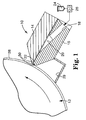
- Figures 1 and 2 show one embodiment of a coating apparatus, in this case an extrusion die 10, positioned relative to a back-up roll 12.
- the extrusion die 10 includes a die top 14, and a die body 16 which can be made of, for example, 15-5 stainless steel.
- a die inlet 18, a die manifold 20, and a die slot 22 are formed between the die top 14 and the die body 16.
- a liquid 24, such as solution, mixture, dispersion, or emulsion, can be supplied by a pump 26 (or other means) to the die 10 for application to a substrate or web 28.
- the liquid 24 can flow through the die inlet 18 to the die manifold 20 for distribution through the die slot 22.
- a bead of the liquid 24 can be applied to the web 28, for example, when the web is transported between the back-up roll 12 and the die 10.
- a vacuum chamber 29 can apply a vacuum to the liquid 24 upstream of the bead to stabilize the bead.
- the liquid 24 can pass through the die slot 22 and form a continuous coating bead along the upstream die lip 30, the downstream die lip 32, and the web 28.
- the liquid 24 can be one of numerous liquids, including water-based liquids, organic solvent-based liquids and 100%-solids fluids.
- the upstream die lip 30 is part of the die body 16, and the downstream die lip 32 is part of die top 14.
- the upstream and downstream die lips 30, 32 can be formed as sharp edges, or can be more rounded, for instance, as a result of polishing.
- the upstream and downstream lips 30, 32 should be clean and relatively free of nicks and burrs.
- the DLSE surface 50 Key portions of the die 10 can be enhanced with a durable, low surface energy surface 50 (hereinafter, the DLSE surface 50).
- the process of providing the die 10 with the DLSE surface 50 is relatively simple and cost-effective.
- the fluorochemical described in the Examples could constitute between 1 to 30 percent of the durable, low surface energy composition, more preferably between 5 to 20 percent, and even more preferably between 7 to 13 percent (Example 1: 10 percent).
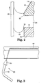
- Figure 2 shows that the DLSE surface 50 can be inlayed on a portion of the die top 14 adjacent to the downstream die lip 32, and on a portion of the die body 16 adjacent to the upstream die lip 30.
- recesses can be cut in the die 10 which can be filled with the priming composition and the durable, low surface energy composition.
- the depth of the inlay can range, for example, from 0.01 to 0.2500 millimeter, although a shallower or deeper inlay is feasible.
- the width of inlay can range, for example, from 1 to 250 millimeter, although a narrower or wider inlay is feasible.
- the length of the inlay is preferably the same as the die width.
- the die body 16 and/or the die top 14 can be cut such that the DLSE surface 50 is inlayed just slightly back from the die lip, as shown. This approach creates a small land at the die lip. Instead, the die body 16 and/or the die top 14 can be cut such that the DLSE surface 50 is applied right to the die lip. If this approach is used, it is preferred to polish the die lip with a mild abrasive to leave a smooth die lip surface. Another option involves having the DLSE surface 50 go beyond the die lip and into the die slot 22. Still another option simply involves applying the DLSE surface 50 onto the die body 16 and/or the die top 14 without cutting a depth to inlay the DLSE surface 50.
- the method can include the steps: (a) preparing specific portions of the die 10 for the DLSE surface 50, (b) priming the prepared portions with a primer composition, (c) curing the primer composition, (d) roughening the set primer composition, (e) applying a durable, low surface energy composition to the primed portions, and (f) curing the durable, low surface energy component.
- the preparing step can accomplish one or two objectives: first, to provide better adhesion between the die 10 and the primer composition, and second, to provide a recess into which the primer and durable, low surface energy composition can be applied.
- a recess or trough can be machined into the portion of the die where the DLSE surface 50 will be located.
- the portion of the die where the DLSE surface 50 will be located can be roughened. Roughening can be accomplished in a number of ways, including grit blasting, hand sanding with fine abrasive paper, and chemical etching with strong acid.
- Figure 3 illustrates a grit blasting apparatus 60 which is made up of commercially available components.
- the grit blasting apparatus 60 can direct an abrasive powder at the die 10 to roughen the surface of the desired portion of the die 10.
- the grit blasting apparatus 60 can include a blast enclosure (not shown), an air compressor or a compressed nitrogen source (not shown), air or nitrogen pressure controls (not shown), an abrasive particle hopper (not shown), conduit 62, nozzle 64, nozzle-pivoting apparatus (not shown), and a workpiece translating apparatus (not shown).
- the enclosure and the hopper are available from Empire Abrasive Equipment Corp. (2101 West Cabot Blvd., Langhorne, PA, 19407) and are referred to as PRO-FINISH Model PF-3696.
- the controls, conduit 62, nozzles 64, and the abrasive powder are available from COMCO Inc. (2151 North Lincoln Street, Burbank, CA 91504).
- a preferred nozzle arrangement includes two nozzles which are positioned side-by-side.
- a preferred nozzle is the COMCO Model MB 1500-23 nozzle (rectangular orifice, 3.8 millimeters by 0.02 millimeters).
- the nozzle-pivoting or - oscillating apparatus includes a Model S57-83-MO stepper motor and Model S6 drive which are available from Compumotor Division of Parker Hannifin Corp. (5500 Business Park Drive, Rohnert Park, CA 94928-7902).
- MicroBlaster Precision abrasive powders are available from COMCO, such as Silicon Carbide powder and Aluminum Oxide powder.
- Silicon Carbide powder having a 10- to 100-micron particle size is preferred, although other sizes and powders are acceptable.
- the nozzles 64 can be pointed toward a workpiece, such as a die body 16 (or a die top 14), such that the abrasive particles strike a surface of the die body 16 leaving an abraded portion 66.
- the die body 16 can be masked with tape such that only the desired portion of the die body 16 is struck by the abrasive particles.
- air pressure is preferably set at 100 pounds per square inch; the orifices of the nozzles 62 are preferably positioned 1.25 centimeters from the die body 16; and, the nozzles are translated across the die body 16 at a rate of 2.5 centimeters per minute and pivoted or reciprocated at a rate of 24 cycles per second.
- the nozzle is pivoted or oscillated across a 26 degree range (from -13 degrees from horizontal to +13 degrees from horizontal).
- the nozzle is translated across the die component at a rate of 2.5 cm/minute.
- Other rates, distances and ranges, however, have been shown to provide the abraded portion 66. (Other abrading techniques could be used including the use of sandpaper or other roughening materials.)
- the priming step which is particularly useful when applying the DLSE surface 50 to a stainless steel component, can involve leveling the die 10 and applying a primer composition to the abraded portion 66 of the die 10.
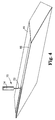
- a formulation of the primer composition is described in the Examples Section, although variations of that formulation and other formulations could be used. While the primer composition could be brushed or sprayed onto a portion or portions of the die 10, Figure 4 schematically illustrates a preferred priming approach.
- This approach can involve the steps of: (a) positioning the abraded portion 66 of the die body 16 (or die top 14) relative to a composition applicator 70 and such that the abraded portion 66 is level, (b) translating the composition applicator 70 at a controlled velocity relative to the die body 16, (c) controlling the volumetric rate of primer composition from the composition applicator 70 to the die body 16, and (d) allowing the primer composition to spread over the abraded portion 66 of the die body 16.
- the composition applicator 70 include a needle 72, syringe 74, and an actuating mechanism (not shown) for compressing the syringe at a controlled rate.
- An actuating mechanism is a 74900 Series syringe pump, which is commercially available from Cole-Parmer Instruments Company (7425 N. Oak Park Avenue, Niles, IL 60714).
- the primer composition is preferably dispensed at a rate of 7.0 cubic centimeters per hour and the applicator 70 is preferably translated at a rate of 15.2 centimeters per minute.
- the die body 16 After dispensing the primer composition down the length of the abraded portion 66, the die body 16 remains stationary for the necessary time for the primer composition to flow outwardly and cover the abraded portion 66.
- a small paint brush with all but a few brush fibers removed, can be used to spread the primer composition to any area uncovered by the primer composition.
- the primer composition is subjected to ultraviolet radiation to cure the composition.
- An ultraviolet radiation source available from XENON Corporation (20 Commerce Way, Woburn MA 01801), can pulse the ultraviolet radiation tube at a particular rate and for a particular duration.
- the ultraviolet radiation tube is preferably positioned 0.5 to 5 centimeters above the primer composition and preferably pulsed at a rate of 7 bursts per second and for a duration of 5 to 60 seconds.
- the preferred ultraviolet tube is Model 890-1741 which has an energy output of approximate 209 joules and which is available from XENON.
- the primed surface is preferably grit blasted to allow for improved adhesion between the primed surface and the durable, low surface energy composition (hereinafter, DLSE composition).
- DLSE composition durable, low surface energy composition
- the same nozzles 64 as previously mentioned can be used, but with a Silicon Carbide powder (20 micron particle size available from COMCO).
- the air pressure is 70 pounds per square inch; the distance from the orifice of the nozzles 64 to the workpiece is 25.4 millimeters; the nozzles 64 are pivoted at a rate of 24 cycles per second; and, the nozzle is translated through the die component at a rate of 15.2 centimeters per minute.
- the DLSE composition can be applied to the abraded, primed surface using the composition applicator 70 and following the same steps as those previously described for applying the primer composition.
- the applications of the primer and the DLSE compositions could instead be done with an electrostatic sprayer, by simply using a dropper, by brushing, and even by dipping the component into the compositions.
- the durable low surface energy composition can be cured using the previously described curing equipment.
- the pulsed ultraviolet radiation is preferably applied for a duration of 18 seconds.
- a final step can involve polishing the DLSE surface 50 at the very tip of the downstream die lip 32 to remove or reduce the roughness at the tip which can be caused by the grit blasting step. But, this step is only advisable if the DLSE composition has been applied right up to the very tip of the die lip 32.
- the previously described method for applying the DLSE surface 50 to a portion of a die body 16 and/or a die top 14 should be compared with the method for applying a fluorinated polyethylene coating (e.g., polytetrafluoroethylene-PTFE) to a die part.
- a fluorinated polyethylene coating e.g., polytetrafluoroethylene-PTFE
- a comparative example describes such a PTFE process.
- the PTFE coating and process is significantly different from the DLSE coating and process in several ways. First, while the PTFE coating can be abraded to some degree and still provide a low surface energy surface, the PTFE coating is relatively soft and can be rendered ineffective when a web tears in process and strikes the PTFE coating with sufficient force. The DLSE coating is significantly less susceptible to this sort of impact.
- the process of applying the PTFE is far more time-consuming than the DLSE process. This is significant because manufacturers strive to minimize production downtime, such as minimizing the time to have a die part coated or recoated. It is generally estimated that the time required to apply the PTFE composition is many times greater than the time required to apply the DLSE composition. This can have a very serious impact on production scheduling, production efficiencies, and capital investment.
- the PTFE process involves subjecting the die part to a significantly higher temperature than the DLSE process.
- the DLSE process can include heating the die part to between, for example, about 80 and about 140 degrees Fahrenheit (about 27 to 49 degrees Celsius), but more preferably to about 110 degrees Fahrenheit (43 degrees Celsius).
- the DLSE process can include heating the die part to between, for example, about 80 and about 140 degrees Fahrenheit (about 27 to 49 degrees Celsius), but more preferably to about 110 degrees Fahrenheit (43 degrees Celsius).
- significant care must be taken to prevent dimensional changes and distortions within the die parts. This can be critical in that the surface of these die parts are commonly precision ground to allow for the precision coating when the die is in use, and dimensional changes can render a die part ineffective.
- preparing a PTFE coating involves several more steps (e.g., multiple PTFE layers, final grinding of the PTFE coating) and can involve more handling of the die part being treated. More handling can increase the risk that a critical surface of a die part will inadvertently strike another object and be damaged by the impact. Damage to a critical surface of a die part can result in the need to regrind the surface or, worse yet, the need to replace the damaged die part all together. Both of these results can, of course, cause further production downtime and significant expense.
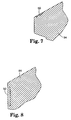
- Figure 5 illustrate an embodiment of a slide coating apparatus 80 which includes a DLSE surface 50 on two portions of the apparatus 80 which contacts the liquid 24.
- the slide coating apparatus 80 includes a slide assembly 82 and a slide back-up roll 84.
- the slide assembly 82 includes a number of slide blocks 86, 88, 90, 92, 94 which can simultaneously deliver multiple layers of liquid 24 to the web 28.
- Figures 6-8 more specifically show the locations of the DLSE surface 50 on the slide coating apparatus 80.
- Figures 6-7 illustrate that the DLSE surface 50 can be applied to the top surface of the last slide block 94 to minimize the wetting of the top surface by the liquid 24 flowing down the slide coating apparatus 80.
- Figure 6 shows edge guides 96 positioned to guide the liquid 24 toward the back-up roll 84 and the web 28.
- the DLSE surface 50 can be applied to the portions of the edge guides 96 which can minimize the wetting of the liquid 24 on the edge guides 96. If made of stainless steel, the edge guides 96 should be roughened and primed as previously discussed. But, if made of plastic (e.g., SL5170 epoxy from Ciba-Geigy), the DLSE composition can be applied without the roughening and priming steps.
- the presence of the DLSE surface 50 on the portions of the edge guides which contact the coating fluid minimizes the wetting of the edge guides or a portion thereof. This can minimize the build-up/drying of coating solids on the edge guides which can adversely affect the quality of the coating.
- Figure 8 shows the surface of the first slide block 86 which is adjacent to the back-up roll 84.
- This surface can include a DLSE surface 50 to minimize the wetting of the liquid 24 down this surface of the first slot block 86. This, in turn, minimizes the build-up of coating solids and the related adverse consequences.
- the DLSE surface 50 could be applied to portions of the extrusion die 10 and the slide assembly 82 other than those previously described, and to other coating apparatuses and fluid contacting surfaces.
- the DLSE surface 50 could provide a durable, low surface energy surface for apparatuses or components other than those involved in the process of applying liquids to substrates.
- variations of the DLSE surface 50, other than those already described, are contemplated by the Applicants and should be considered as part of the disclosed invention.
- EtFOSEMA is N-ethyl-perfluoro(octane)sulfonamidoethyl methacrylate, and is available from 3M Company, St. Paul, MN.
- ⁇ -glycidoxypropyl trimethoxysilane is available under the name Z-6040 from Dow Chemical Company, Midland, MI. It is also available under the name A-187 from OSi Specialties Inc, Danbury, CT.
- Triphenylsulfonium hexafluoroantimonate was obtained from 3M Company, St. Paul, MN. It is also available from Union Carbide, Danbury, CT.
- Carbowax 750 is a polyethylene glycol monomethyl ether available from Union Carbide, Danbury, CT. It is believed to have the approximate formula CH 3 O-(CH 2 CH 2 O) 16 -OH.
- Carbowax 750 acrylate is the reaction product between Carbowax 750 and acrylic acid.
- the preparation of Carbowax 750 acrylate is described in Example 2 of U.S. Patent No. 3,787,351 (Olson).
- Fluorochemical Oligomer A fluorochemical oligomer was prepared as described in Example 1, part A of U.S. Patent No. 5,468,812.
- the bottle and contents were deaerated under reduced pressure, purged with nitrogen, capped tightly, then heated and agitated in a Launder-O-Meter at 65°C for 16 hours to afford a fluorochemical oligomer.
- the bottle was cooled, degassed under reduced pressure, purged with air, and used in the next step.
- the solution contained 48 wt% of oligomer in ethyl acetate.
- the oligomer contained 34.5% fluoroaliphatic monomer, 54.0% organic solubilizing monomer, and 11.5% bifunctional monomer.
- a durable, low energy surface polymer was prepared by mixing the following:
- the fluorochemical oligomer comprised 10 wt%
- the triphenylsulfonium hexafluoroantimonate comprised 4 wt%
- the ⁇ -glycidoxypropyl trimethoxysilane (Z-6040) comprised 86 wt%.
- Primer Composition A primer composition was prepared by mixing the following:
- Gas (nitrogen) pressure was set at 100 lb/in 2 (6.89x10 2 kPa); the orifices of the nozzles 62 were positioned 1.25 cm from the die body 16; and, the nozzles were translated across the die component at a rate of 2.5 cm/min and pivoted or reciprocated at a rate of 24 cycles/min.
- FIG. 4 schematically illustrates a preferred priming approach. This approach involved the steps of: (a) positioning the abraded portion 66 of the die body 16 (or die top 14) relative to a composition applicator 70 and such that the abraded portion 66 is level, (b) translating the composition applicator 70 at a controlled velocity relative to the die body 16, (c) controlling the volumetric rate of primer composition from the composition applicator 70 to the die body 16, and (d) allowing the primer composition to spread over the abraded portion 66 of the die body 16.
- the composition applicator 70 included a needle 72, syringe 74, and an actuating mechanism 76 for compressing the syringe at a controlled rate.
- the primer composition When applying the primer composition to the abraded portion 66 which was approximately 12.5 mm wide and 0.08 mm deep, the primer composition was dispensed at a rate of 7.0 cm 3 /hour and the composition applicator 70 was preferably translated at a rate of 15.2 cm/min. After dispensing the primer composition down the length of the abraded portion 66, the die body 16 was held stationary for the necessary time for the primer composition to flow outwardly and cover the abraded portion 66. A small paint brush, with all but a few brush fibers removed, was used to spread the primer composition to any area uncovered by the primer composition.
- the primer composition was subjected to previously described XENON, ultraviolet radiation source to cure the composition.
- the ultraviolet radiation tube was positioned approximately 1.6 cm above the primer composition and pulsed at a rate of 10 bursts per second for 60 seconds.
- the primed surface was grit blasted using the same nozzles 64 as previously mentioned, but with a Silicon Carbide powder (20 ⁇ m particle size).
- Gas (nitrogen) pressure was 70 lb/in 2 (4.83x10 2 kPa); the distance from the orifice of the nozzles 64 to the workpiece was 25.4 mm; the nozzles 64 were pivoted at a rate of 24 cycles/sec; and, the nozzles were translated such that the nozzle streams moved across the die body 16 at a rate of 15.2 cm/min.
- dispensed rate is preferably 5 cm 3 /hr.
- the DLSE composition was cured using the previously described curing equipment.
- the pulsed ultraviolet radiation was applied for a duration of 18 seconds.
- the very tip of the downstream die lip 32 was polished to remove or reduce the roughness at the tip which can be caused by the grit blasting step. Care is required at this step to minimize the abrading of the DLSE surface 50.
- compositions and this process of preparing the extrusion die provided a low surface energy to the treated surface.
- Contact angle measurements of the DLSE surface 50 with water, a 6.4% MEK in water solution, and 100% MEK gave contact angles of 100.1 degrees, 69.2 degrees, and 43.6 degrees, respectively.
- the DLSE surface 50 was observed to reduce streaking even after a web broke and directly struck the DLSE surface 50.
- Example 2 is similar to Example 1 except that the fluorochemical oligomer in ethyl acetate was at 1% solids, rather than 10%. This composition change provided similar performance results to those provided by the composition in Example 1.
- Example 3 is similar to Example 1 except that the fluorochemical oligomer in ethyl acetate was at 5% solids, rather than 10%. This composition change provided similar performance results to those provided by the composition in Example 1.
- Example 4 is similar to Example 1 except that the fluorochemical oligomer in ethyl acetate was at 20% solids, rather than 10%. This composition change provided similar performance results to those provided by the composition in Example 1.
- a polytetrafluoroethylene (PTFE) coating was applied to a die part, including a die top and a die body. Approximately the same preparation as that described in the previous examples was used including the grit blasting the die part surface.
- a primer was prepared by agitating the primer and filtering it through a 150 mesh stainless steel wire screen or cheese cloth. The primer was applied to die part surface using the same approach as that described in previous examples. The desired dried coating thickness of the primer was 0.001 inch (25.4 ⁇ m). The primer was air dried for 1-5 minutes, then was placed into an oven and slowly heated to 400-450 °F (204-232 °C) for 10 minutes. The oven was then turned off so that the die part could cool to approximately room temperature. The primer used was 856-204 series, green polytetrafluoroethylene non-stick primer (available from DuPont). The die part surface was then cleaned and degreased.
- the PTFE top coating was then prepared (856-200 series clear top coat, DuPont) by gently agitating or stirring for 15-30 minutes and filtered through a 100-mesh stainless steel screen.
- the die part was preheated to 120-140 °F (48.8-60.0 °C) and the top coating was left at room temperature.
- the top coating was then sprayed onto the primed surface at 40-50 lb/in 2 (2.76 x10 2 - 3.45 x 10 2 kPa).
- the maximum thickness for the dried top coating was 0.001 inch (25.4 ⁇ m).
- top-coated die part was then placed back into the oven and slowly heated to 575 °F (301.7 °C) for 60 minutes. Then, the die part was allowed to slowly cool down to at least 150 °F (65.6 °C). Then, additional layers of the top coat and additional heat-up and cool-down steps were taken to create a final dry top coating thickness of 0.004-0.006 inch (101.6-152.4 ⁇ m) (i.e., at least three to five repetitions).
Landscapes
- Chemical & Material Sciences (AREA)
- General Chemical & Material Sciences (AREA)
- Health & Medical Sciences (AREA)
- Chemical Kinetics & Catalysis (AREA)
- Medicinal Chemistry (AREA)
- Polymers & Plastics (AREA)
- Organic Chemistry (AREA)
- Paints Or Removers (AREA)
- Addition Polymer Or Copolymer, Post-Treatments, Or Chemical Modifications (AREA)
- Application Of Or Painting With Fluid Materials (AREA)
- Compositions Of Macromolecular Compounds (AREA)
- Silicon Polymers (AREA)
Applications Claiming Priority (3)
| Application Number | Priority Date | Filing Date | Title |
|---|---|---|---|
| US659053 | 1996-05-31 | ||
| US08/659,053 US5998549A (en) | 1996-05-31 | 1996-05-31 | Durable, low surface energy compounds and articles, apparatuses, and methods for using the same |
| PCT/US1997/006882 WO1997046598A1 (en) | 1996-05-31 | 1997-04-23 | Durable, low surface energy compounds and articles, apparatuses, and methods for using the same |
Publications (2)
| Publication Number | Publication Date |
|---|---|
| EP0902797A1 EP0902797A1 (en) | 1999-03-24 |
| EP0902797B1 true EP0902797B1 (en) | 2000-11-15 |
Family
ID=24643839
Family Applications (1)
| Application Number | Title | Priority Date | Filing Date |
|---|---|---|---|
| EP97923453A Expired - Lifetime EP0902797B1 (en) | 1996-05-31 | 1997-04-23 | Durable, low surface energy compounds and articles, apparatuses, and methods for using the same |
Country Status (11)
| Country | Link |
|---|---|
| US (2) | US5998549A (enExample) |
| EP (1) | EP0902797B1 (enExample) |
| JP (2) | JP2000511955A (enExample) |
| KR (1) | KR20000016057A (enExample) |
| CN (1) | CN1220673A (enExample) |
| AR (1) | AR007344A1 (enExample) |
| AU (1) | AU2925297A (enExample) |
| BR (1) | BR9709283A (enExample) |
| CA (1) | CA2255583A1 (enExample) |
| DE (1) | DE69703547T2 (enExample) |
| WO (1) | WO1997046598A1 (enExample) |
Families Citing this family (37)
| Publication number | Priority date | Publication date | Assignee | Title |
|---|---|---|---|---|
| US5998549A (en) * | 1996-05-31 | 1999-12-07 | 3M Innovative Properties Company | Durable, low surface energy compounds and articles, apparatuses, and methods for using the same |
| US5861195A (en) | 1997-01-21 | 1999-01-19 | Minnesota Mining And Manufacturing Company | Method for coating a plurality of fluid layers onto a substrate |
| US8653213B2 (en) | 1997-02-03 | 2014-02-18 | Cytonix, Llc | Hydrophobic coating compositions and articles coated with said compositions |
| US7268179B2 (en) * | 1997-02-03 | 2007-09-11 | Cytonix Corporation | Hydrophobic coating compositions, articles coated with said compositions, and processes for manufacturing same |
| US6156389A (en) | 1997-02-03 | 2000-12-05 | Cytonix Corporation | Hydrophobic coating compositions, articles coated with said compositions, and processes for manufacturing same |
| US6495624B1 (en) * | 1997-02-03 | 2002-12-17 | Cytonix Corporation | Hydrophobic coating compositions, articles coated with said compositions, and processes for manufacturing same |
| US6391807B1 (en) | 1999-09-24 | 2002-05-21 | 3M Innovative Properties Company | Polymer composition containing a fluorochemical oligomer |
| US6174964B1 (en) * | 1999-09-24 | 2001-01-16 | 3M Innovative Properties Company | Fluorochemical oligomer and use thereof |
| US6342324B1 (en) | 2000-02-16 | 2002-01-29 | Imation Corp. | Release layers and compositions for forming the same |
| DE10196461T1 (de) | 2000-07-27 | 2003-06-05 | Imation Corp | Magnetische Aufzeichnungsmedien und Beschichtungsverfahren |
| DE60127527T2 (de) | 2001-01-19 | 2007-12-13 | 3M Innovative Properties Co., St. Paul | Wasserlösliche oder in Wasser dispergierbare fluorochemische Silane, um Substrate öl- und wasserabstossend zu machen |
| EP1225187B1 (en) * | 2001-01-19 | 2009-05-27 | 3M Innovative Properties Company | Fluorovinyl oligomer component having silane groups, liquid compositions thereof and method of coating |
| US6645618B2 (en) | 2001-06-15 | 2003-11-11 | 3M Innovative Properties Company | Aliphatic polyester microfibers, microfibrillated articles and use thereof |
| US6813820B2 (en) * | 2001-12-19 | 2004-11-09 | 3M Innovative Properties Company | Method of improving coating uniformity |
| US6789741B2 (en) * | 2002-03-27 | 2004-09-14 | S. C. Johnson & Son, Inc. | Method and apparatus for atomizing liquids having minimal droplet size |
| US6890649B2 (en) * | 2002-04-26 | 2005-05-10 | 3M Innovative Properties Company | Aliphatic polyester microfibers, microfibrillated articles and use thereof |
| EP1369453B1 (en) * | 2002-06-03 | 2006-11-29 | 3M Innovative Properties Company | Fluoro-Silane-Oligomer composition |
| US20040001921A1 (en) * | 2002-06-26 | 2004-01-01 | Imation Corp. | Coating in an environment that includes solvent vapor |
| US6960385B2 (en) * | 2002-09-10 | 2005-11-01 | Imation Corp. | Magnetic recording medium |
| WO2005028123A1 (en) * | 2003-09-17 | 2005-03-31 | 3M Innovative Properties Company | Methods for forming a coating layer having substantially uniform thickness, and die coaters |
| US7291362B2 (en) | 2004-01-20 | 2007-11-06 | 3M Innovative Properties Company | Method and apparatus for controlling coating width |
| US7585919B2 (en) * | 2006-09-26 | 2009-09-08 | 3M Innovative Properties Company | Polymer derived from monomers with long-chain aliphatic, poly(oxyalkylene) and substrate-reactive groups |
| US20090074976A1 (en) * | 2007-09-14 | 2009-03-19 | Freking Anthony J | Method of reducing mottle and streak defects in coatings |
| BRPI0819558A2 (pt) * | 2007-12-31 | 2015-05-05 | 3M Innovative Properties Co | "método para aplicação de um material revestidor" |
| BRPI0910877A2 (pt) * | 2008-03-26 | 2015-10-06 | 3M Innovative Proferties Company | método para aplicar dois ou mais fluidos como um revestimento de deslizamento |
| US20110027493A1 (en) * | 2008-03-26 | 2011-02-03 | Yapel Robert A | Methods of slide coating fluids containing multi unit polymeric precursors |
| EP2268417A1 (en) * | 2008-03-26 | 2011-01-05 | 3M Innovative Properties Company | Methods of slide coating two or more fluids |
| US8420069B2 (en) * | 2008-09-26 | 2013-04-16 | 3M Innovative Properties Company | Antimicrobial and antifouling polymeric materials |
| CN102459565A (zh) | 2009-06-02 | 2012-05-16 | 尹特根埃克斯有限公司 | 具有隔膜阀的流控设备 |
| US10947396B2 (en) | 2012-11-13 | 2021-03-16 | 3M Innovative Properties Company | Curable antifouling composition, method of use, and articles |
| CN105705112B (zh) | 2013-10-04 | 2018-02-27 | 3M创新有限公司 | 牙科研磨坯料、牙科修复体以及形成牙科研磨坯料的方法 |
| JP6659716B2 (ja) | 2015-03-05 | 2020-03-04 | スリーエム イノベイティブ プロパティズ カンパニー | セラミック繊維を有する複合材料 |
| CN110880550A (zh) * | 2018-09-05 | 2020-03-13 | 杭州纤纳光电科技有限公司 | 含有表面活性剂的前驱体溶液的涂布设备及其方法 |
| CN112673035B (zh) | 2018-09-14 | 2024-04-19 | 舒万诺知识产权公司 | 包含陶瓷纤维和纳米团簇的复合材料、牙科产品、套件盒及其制备和使用方法 |
| KR102672871B1 (ko) * | 2020-03-05 | 2024-06-05 | 후지필름 가부시키가이샤 | 다이 헤드 |
| JP7266746B2 (ja) * | 2020-03-11 | 2023-04-28 | 富士フイルム株式会社 | ダイヘッド |
| CN116239924B (zh) * | 2022-11-10 | 2023-12-01 | 浙江巨化技术中心有限公司 | 一种电子级防护剂 |
Family Cites Families (32)
| Publication number | Priority date | Publication date | Assignee | Title |
|---|---|---|---|---|
| BE513714A (enExample) * | 1951-08-23 | 1900-01-01 | ||
| US2841573A (en) * | 1955-12-29 | 1958-07-01 | Minnesota Mining & Mfg | Fluorocarbon vinyl-type esters and polymers |
| US2803615A (en) * | 1956-01-23 | 1957-08-20 | Minnesota Mining & Mfg | Fluorocarbon acrylate and methacrylate esters and polymers |
| US3787351A (en) * | 1972-02-28 | 1974-01-22 | Minnesota Mining & Mfg | Use of soluble fluoroaliphatic oligomers in resin composite articles |
| JPS5315743B2 (enExample) * | 1973-08-14 | 1978-05-26 | ||
| US4049861A (en) * | 1975-03-07 | 1977-09-20 | Minnesota Mining And Manufacturing Company | Abrasion resistant coatings |
| US4101513A (en) * | 1977-02-02 | 1978-07-18 | Minnesota Mining And Manufacturing Company | Catalyst for condensation of hydrolyzable silanes and storage stable compositions thereof |
| US4156046A (en) * | 1977-03-28 | 1979-05-22 | Minnesota Mining And Manufacturing Company | Ultraviolet radiation protective, abrasion resistant, bloom resistant coatings |
| US4415615A (en) * | 1982-01-15 | 1983-11-15 | Minnesota Mining And Manufacturing Co. | Cellular pressure-sensitive adhesive product and method of making |
| US4445548A (en) | 1982-01-25 | 1984-05-01 | Franz Neumann | Food portioning machine |
| US4443504A (en) * | 1982-06-09 | 1984-04-17 | E. I. Du Pont De Nemours & Company | Coating method |
| US4445458A (en) * | 1982-07-21 | 1984-05-01 | E. I. Du Pont De Nemours And Company | Beveled edge metered bead extrusion coating apparatus |
| US4560599A (en) * | 1984-02-13 | 1985-12-24 | Marquette University | Assembling multilayers of polymerizable surfactant on a surface of a solid material |
| EP0153133B1 (en) * | 1984-02-13 | 1991-12-04 | Marquette University | Assembling multilayers of polymerizable surfactant on a surface of a solid material |
| NL8502463A (nl) * | 1985-09-10 | 1987-04-01 | Dsm Resins Bv | Samenstelling op basis van een waterige dispersie van een additiepolymeer. |
| GB8710912D0 (en) * | 1987-05-08 | 1987-06-10 | Unilever Plc | Emulsion copolymerisation |
| US4853737A (en) * | 1988-05-31 | 1989-08-01 | Eastman Kodak Company | Roll useful in electrostatography |
| GB8829147D0 (en) * | 1988-12-14 | 1989-01-25 | Unilever Plc | Emulsion polymers |
| US5242972A (en) * | 1989-04-05 | 1993-09-07 | Kansai Paint Co., Ltd. | Fluorine based aqueous dispersion, process for preparing the same, and fluorine based matte anionic electrodeposition coating composition containing the same |
| JPH0347853A (ja) * | 1989-04-05 | 1991-02-28 | Kansai Paint Co Ltd | フッ素系水性分散液、フッ素系水性分散液の製造方法及びその分散液を含有するフッ素系艶消しアニオン形電着塗料組成物 |
| DE3918704A1 (de) * | 1989-06-08 | 1990-12-13 | Huels Chemische Werke Ag | Verfahren zur herstellung von waessrigen, siliciummodifizierten kunststoffdispersionen und ihre verwendung |
| JPH04110350A (ja) * | 1990-08-30 | 1992-04-10 | Kansai Paint Co Ltd | 硬化性樹脂組成物及びその硬化方法 |
| WO1992017515A1 (en) * | 1991-04-02 | 1992-10-15 | Minnesota Mining And Manufacturing Company | Polymerizable fluorochemical surfactants and acrylate adhesives containing them |
| US5468812A (en) * | 1991-04-02 | 1995-11-21 | Minnesota Mining And Manufacturing Company | Polymerizable fluorochemical surfactants |
| US5380365A (en) * | 1992-01-21 | 1995-01-10 | E. I. Du Pont De Nemours And Company | Lip surface geometry for slide bead coating |
| DE69309572T2 (de) * | 1992-01-22 | 1997-09-04 | Konishiroku Photo Ind | Auftragsverfahren und -vorrichtung |
| CA2089963C (en) * | 1992-03-24 | 1999-03-16 | Solomon T. Korokeyi | A liquid passage system for photographic coating devices |
| US5532121A (en) * | 1995-03-24 | 1996-07-02 | Minnesota Mining And Manufacturing Company | Mottle reducing agent for photothermographic and thermographic elements |
| JPH091028A (ja) * | 1995-06-12 | 1997-01-07 | Konica Corp | 塗布装置 |
| US5998549A (en) * | 1996-05-31 | 1999-12-07 | 3M Innovative Properties Company | Durable, low surface energy compounds and articles, apparatuses, and methods for using the same |
| US5843530A (en) * | 1997-01-21 | 1998-12-01 | Minnesota Mining And Manufacturing Company | Method for minimizing waste when coating a fluid with a slide coater |
| JPH10307381A (ja) * | 1997-03-04 | 1998-11-17 | Fuji Photo Film Co Ltd | 液体噴射装置及び液体噴射装置の製造方法 |
-
1996
- 1996-05-31 US US08/659,053 patent/US5998549A/en not_active Expired - Fee Related
-
1997
- 1997-04-23 AU AU29252/97A patent/AU2925297A/en not_active Abandoned
- 1997-04-23 JP JP10500565A patent/JP2000511955A/ja not_active Ceased
- 1997-04-23 BR BR9709283A patent/BR9709283A/pt not_active IP Right Cessation
- 1997-04-23 KR KR1019980709624A patent/KR20000016057A/ko not_active Withdrawn
- 1997-04-23 CA CA002255583A patent/CA2255583A1/en not_active Abandoned
- 1997-04-23 EP EP97923453A patent/EP0902797B1/en not_active Expired - Lifetime
- 1997-04-23 WO PCT/US1997/006882 patent/WO1997046598A1/en not_active Ceased
- 1997-04-23 DE DE69703547T patent/DE69703547T2/de not_active Expired - Fee Related
- 1997-04-23 CN CN97195111A patent/CN1220673A/zh active Pending
- 1997-05-30 AR ARP970102327A patent/AR007344A1/es not_active Application Discontinuation
-
1999
- 1999-11-16 US US09/442,166 patent/US6231929B1/en not_active Expired - Lifetime
-
2007
- 2007-07-09 JP JP2007180047A patent/JP2007302899A/ja active Pending
Also Published As
| Publication number | Publication date |
|---|---|
| BR9709283A (pt) | 1999-08-10 |
| AU2925297A (en) | 1998-01-05 |
| KR20000016057A (ko) | 2000-03-25 |
| WO1997046598A1 (en) | 1997-12-11 |
| EP0902797A1 (en) | 1999-03-24 |
| US5998549A (en) | 1999-12-07 |
| CN1220673A (zh) | 1999-06-23 |
| AR007344A1 (es) | 1999-10-27 |
| JP2000511955A (ja) | 2000-09-12 |
| JP2007302899A (ja) | 2007-11-22 |
| DE69703547T2 (de) | 2001-06-21 |
| DE69703547D1 (de) | 2000-12-21 |
| CA2255583A1 (en) | 1997-12-11 |
| US6231929B1 (en) | 2001-05-15 |
Similar Documents
| Publication | Publication Date | Title |
|---|---|---|
| EP0902797B1 (en) | Durable, low surface energy compounds and articles, apparatuses, and methods for using the same | |
| US11851570B2 (en) | Anionic polishing pads formed by printing processes | |
| US6245833B1 (en) | Ceramer composition incorporating fluoro/silane component and having abrasion and stain resistant characteristics | |
| AU741534B2 (en) | Abrasion and stain resistant curable fluorinated coating | |
| US5837745A (en) | UV curable polish and method of use | |
| US5980992A (en) | Fluorochemical treatments to provide low-energy surfaces | |
| US4773920A (en) | Coated abrasive suitable for use as a lapping material | |
| JP2550195B2 (ja) | コーティング用またはモールディング用組成物 | |
| JPH09500672A (ja) | ビニルエーテル官能性樹脂を含む研磨製品 | |
| US20030024170A1 (en) | Discrete particles that include a polymeric material and articles formed therefrom | |
| JP4187061B2 (ja) | 車輌塗装面の修理方法 | |
| EP1076677B1 (en) | Ceramer composition having abrasion and stain resistant characteristics | |
| US5468812A (en) | Polymerizable fluorochemical surfactants | |
| CA1263240A (en) | Coated abrasive suitable for use as a lapping material | |
| JP2010228316A (ja) | 三次元造形物の製造方法 | |
| AU1754792A (en) | Polymerizable fluorochemical surfactants and acrylate adhesives containing them | |
| WO2002074492A2 (en) | Abrasive particles that include a polymeric material and abrasive articles made from them | |
| JP4151086B2 (ja) | 高分子被膜を有するガラス製品 | |
| JPH11217451A (ja) | フッ素含有重合体被膜及びその製造方法 | |
| JP4123658B2 (ja) | 硬化性樹脂組成物、硬化物および反射防止膜積層体 | |
| KR102647721B1 (ko) | 올리고머 헥사플루오로프로필렌 옥사이드 유도체 | |
| CA1339614C (en) | Low adhesion compositions of perfluoropolyethers | |
| JPH02233717A (ja) | 硬化性組成物 |
Legal Events
| Date | Code | Title | Description |
|---|---|---|---|
| PUAI | Public reference made under article 153(3) epc to a published international application that has entered the european phase |
Free format text: ORIGINAL CODE: 0009012 |
|
| 17P | Request for examination filed |
Effective date: 19981215 |
|
| AK | Designated contracting states |
Kind code of ref document: A1 Designated state(s): DE FR GB IT |
|
| 17Q | First examination report despatched |
Effective date: 19990304 |
|
| GRAG | Despatch of communication of intention to grant |
Free format text: ORIGINAL CODE: EPIDOS AGRA |
|
| GRAG | Despatch of communication of intention to grant |
Free format text: ORIGINAL CODE: EPIDOS AGRA |
|
| GRAG | Despatch of communication of intention to grant |
Free format text: ORIGINAL CODE: EPIDOS AGRA |
|
| GRAH | Despatch of communication of intention to grant a patent |
Free format text: ORIGINAL CODE: EPIDOS IGRA |
|
| GRAH | Despatch of communication of intention to grant a patent |
Free format text: ORIGINAL CODE: EPIDOS IGRA |
|
| GRAA | (expected) grant |
Free format text: ORIGINAL CODE: 0009210 |
|
| AK | Designated contracting states |
Kind code of ref document: B1 Designated state(s): DE FR GB IT |
|
| REF | Corresponds to: |
Ref document number: 69703547 Country of ref document: DE Date of ref document: 20001221 |
|
| ET | Fr: translation filed | ||
| ITF | It: translation for a ep patent filed | ||
| PLBE | No opposition filed within time limit |
Free format text: ORIGINAL CODE: 0009261 |
|
| STAA | Information on the status of an ep patent application or granted ep patent |
Free format text: STATUS: NO OPPOSITION FILED WITHIN TIME LIMIT |
|
| 26N | No opposition filed | ||
| REG | Reference to a national code |
Ref country code: GB Ref legal event code: IF02 |
|
| PGFP | Annual fee paid to national office [announced via postgrant information from national office to epo] |
Ref country code: DE Payment date: 20070531 Year of fee payment: 11 |
|
| PGFP | Annual fee paid to national office [announced via postgrant information from national office to epo] |
Ref country code: GB Payment date: 20070425 Year of fee payment: 11 |
|
| PGFP | Annual fee paid to national office [announced via postgrant information from national office to epo] |
Ref country code: IT Payment date: 20070521 Year of fee payment: 11 |
|
| PGFP | Annual fee paid to national office [announced via postgrant information from national office to epo] |
Ref country code: FR Payment date: 20070417 Year of fee payment: 11 |
|
| GBPC | Gb: european patent ceased through non-payment of renewal fee |
Effective date: 20080423 |
|
| PG25 | Lapsed in a contracting state [announced via postgrant information from national office to epo] |
Ref country code: DE Free format text: LAPSE BECAUSE OF NON-PAYMENT OF DUE FEES Effective date: 20081101 |
|
| REG | Reference to a national code |
Ref country code: FR Ref legal event code: ST Effective date: 20081231 |
|
| PG25 | Lapsed in a contracting state [announced via postgrant information from national office to epo] |
Ref country code: FR Free format text: LAPSE BECAUSE OF NON-PAYMENT OF DUE FEES Effective date: 20080430 |
|
| PG25 | Lapsed in a contracting state [announced via postgrant information from national office to epo] |
Ref country code: GB Free format text: LAPSE BECAUSE OF NON-PAYMENT OF DUE FEES Effective date: 20080423 |
|
| PG25 | Lapsed in a contracting state [announced via postgrant information from national office to epo] |
Ref country code: IT Free format text: LAPSE BECAUSE OF NON-PAYMENT OF DUE FEES Effective date: 20080423 |