EP0902189B1 - Pompe d'alimentation - Google Patents
Pompe d'alimentation Download PDFInfo
- Publication number
- EP0902189B1 EP0902189B1 EP98115711A EP98115711A EP0902189B1 EP 0902189 B1 EP0902189 B1 EP 0902189B1 EP 98115711 A EP98115711 A EP 98115711A EP 98115711 A EP98115711 A EP 98115711A EP 0902189 B1 EP0902189 B1 EP 0902189B1
- Authority
- EP
- European Patent Office
- Prior art keywords
- shaft
- bevel gear
- feed pump
- motor
- transmission means
- Prior art date
- Legal status (The legal status is an assumption and is not a legal conclusion. Google has not performed a legal analysis and makes no representation as to the accuracy of the status listed.)
- Expired - Lifetime
Links
Images

Classifications
-
- F—MECHANICAL ENGINEERING; LIGHTING; HEATING; WEAPONS; BLASTING
- F04—POSITIVE - DISPLACEMENT MACHINES FOR LIQUIDS; PUMPS FOR LIQUIDS OR ELASTIC FLUIDS
- F04D—NON-POSITIVE-DISPLACEMENT PUMPS
- F04D13/00—Pumping installations or systems
- F04D13/02—Units comprising pumps and their driving means
- F04D13/021—Units comprising pumps and their driving means containing a coupling
-
- F—MECHANICAL ENGINEERING; LIGHTING; HEATING; WEAPONS; BLASTING
- F04—POSITIVE - DISPLACEMENT MACHINES FOR LIQUIDS; PUMPS FOR LIQUIDS OR ELASTIC FLUIDS
- F04D—NON-POSITIVE-DISPLACEMENT PUMPS
- F04D13/00—Pumping installations or systems
- F04D13/02—Units comprising pumps and their driving means
- F04D13/06—Units comprising pumps and their driving means the pump being electrically driven
-
- F—MECHANICAL ENGINEERING; LIGHTING; HEATING; WEAPONS; BLASTING
- F04—POSITIVE - DISPLACEMENT MACHINES FOR LIQUIDS; PUMPS FOR LIQUIDS OR ELASTIC FLUIDS
- F04D—NON-POSITIVE-DISPLACEMENT PUMPS
- F04D29/00—Details, component parts, or accessories
- F04D29/18—Rotors
- F04D29/20—Mounting rotors on shafts
Definitions
- the invention relates to a feed pump which is driven by a motor and especially used with a wet grist in beer production can.
- a feed pump that is driven by a motor and for transmission the driving force uses a bevel gear, for example from the GB 1,065,194 A known.
- the pump also has a shaft-driven one Pump mechanism on, with a first bevel gear around the same axis rotates as the shaft and is driven by a first transmission means and a second bevel gear driven by a second transmission means from the engine becomes.
- the material to be shot is mixed with water and fed to the grinder of a wet grist mill.
- the grinder of a wet grist mill There is the thing to be crushed Good e.g. grind between two rollers.
- the crushed good is below the grinder with the help of a feed pump.
- the crushed material is extracted using an eccentric screw pump, arranged at the outlet end of the wet grist mill and serves as a feed pump.
- an eccentric screw pump shows a high due to the abrasive behavior of the mash Wear and is therefore maintenance-intensive.
- feed pump which is at the outlet end of a wet grist mill can be attached, closes below the suction port, the e.g. can be flanged to the wet grist mill, a pump housing in to which an impeller pumps the material to be pumped from above onto the impeller Transport through a pressure port presses.
- the impeller is at the top End of a driven shaft attached.
- the shaft of the feed pump is by means of a employed bearing stored in a bearing block, which is attached to the pump housing from below is attached.
- the lower end of the shaft protrudes downwards from the bearing housing out.
- a pulley is attached to this lower end of the shaft, which is driven by an electric motor to the shaft and a belt to set the pump impeller in rotation.
- the height is essentially due to the length of the Bearing blocks for the vertical shaft with the one at the lower end Pulley determined. If you use commercially available bearings, So those that can be mass-produced have bearings use with a certain minimum length, which is the overall height of the entire Pump unit would enlarge. In order to get a lower overall height therefore specially designed bearings are used, which are relatively expensive.
- the object of the invention is to provide a Specify feed pump, which is manufactured more cheaply despite the low overall height can be used as well-known feed pumps and in particular for use with a Wet grist mill is suitable.
- the feed pump according to the invention has the drive transmission from the engine Feed pump on a bevel gear.
- a bevel gear is also inexpensive and robust and is also subject to much less wear and tear than a belt drive.
- the feed pump comprises a pump impeller with an essentially vertical, driven shaft that is rotatably mounted.
- a pump impeller enables a robust and failure-prone construction. This can be done simply be provided that a first bevel gear of the bevel gear by the same
- the axis is rotatable like the shaft and the shaft via a first transmission means drives and a second bevel gear of the bevel gear via a second transmission means is driven by the engine.
- the first transmission means for transmitting the Driving force on the shaft is a hollow shaft which is connected to the first bevel gear and rotated by it, the shaft with a collar on the top End face of the hollow shaft rests. At the other end of the shaft, you can use the shaft be attached to a shaft nut. This is a safe and precise storage the shaft is guaranteed by the axial forces that occur during pump operation occur optimally.
- the bevel gears are advantageously with axes perpendicular to one another arranged. Such an arrangement enables an optimal reduction in Height of the feed pump, since the motor can be mounted essentially horizontally can.
- first transmission means for transmitting the driving force to the shaft an element includes the driving force of the hollow shaft by positive locking on the shaft wearing.
- Such an arrangement is very simple and can be easily, e.g. for cleaning purposes, disassemble and reassemble.
- positive locking transmission is robust and not susceptible to interference.
- the element for transmitting the driving force is on the shaft a key.
- the second transmission means comprises Transmission of the driving force from the motor to the second bevel gear of the bevel gear a drive shaft with a detachable connection. This way easily disconnect the bevel gear from the engine. In addition, such a releasable Connection easy replacement of the bevel gear.
- the motor for driving the bevel gear is simply an electric motor, which is connected to the bevel gear housing via a flange connection.
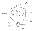
- a wet grist mill with which the feed pump according to the invention is advantageously used can be comprises a grinder, which consists of two rollers 31, 32 which in a container 30 are arranged.
- the container 30 has a shot feed 34.
- the pump housing closes at the suction nozzle 17 1 in which the pump impeller 2 rotates.
- the pump impeller 2 is on one Shaft 9 mounted, which is arranged vertically. 16 denotes the pressure port, through which the impeller removes the crushed material.
- the pump housing 1 is from completed below with a pump base plate 13, which is made using a flange 3 is attached to the pump housing 1.
- the pump room is with the help of a shaft seal 5 on the implementation of the shaft the pump base plate is sealed off from the space in the spacer lantern 4.
- the shaft 9 has a shaft collar 24 which a hollow shaft 18 rests.
- the pump shaft extends below the shaft collar 24 9 in this hollow shaft 18 and is via a key 7 with the hollow shaft in Positive engagement.
- a first bevel gear 20 with the same axis as the shaft 9 or the hollow shaft 18 is attached to the outer periphery of the hollow shaft 18.
- the first bevel gear 20 is located in the upper area of the hollow shaft near the adapter flange 6.
- a second bevel gear 19 is in engagement with the first bevel gear 20, which has a horizontal axis.
- the second bevel gear 19 is on an axis 22 driven by an electric motor 12.
- the axis 22 is detachable at a point 21 designed. Junction 21 may e.g. be a plug lock.
- the electric motor 12 is with the help of a flange 15 on a flange 14 of the bevel gear attached and supported by brackets 23.
- Both the bevel gear 8 and the shaft 9 can be mass-produced, commercially available components.
- the bevel gear 8 is easily replaceable.
- the electric motor 12 can be started remove the flange connections 14, 15 so that the bevel gear only is still attached to the spacer bracket 4 by the adapter flange 6. Doing so the shaft 22 is released at the connection 21. Allows loosening this adapter flange a simple pulling off the bevel gear down, because between the Shaft 9 and the hollow shaft 18 of the bevel gear only connect over the key 7 is made. In the operating state, the shaft 9 is not at all or only slightly down over the bevel gear. By the lying electric motor, the The bevel gear enables a low overall height.
- the modular structure with a robust bevel gear represents an economical one Possibility to drive the shaft of the feed pump according to the invention.
Landscapes
- Engineering & Computer Science (AREA)
- Mechanical Engineering (AREA)
- General Engineering & Computer Science (AREA)
- Rotary Pumps (AREA)
- Structures Of Non-Positive Displacement Pumps (AREA)
- Crushing And Grinding (AREA)
Claims (6)
- Pompe d'alimentation qui est entraínée par un moteur (12) et peut être employée en particulier à l'extrémité du côté sortie d'un concasseur par voie humide, un engrenage (8) à pignons coniques étant prévu pour transmettre la force d'entraínement du moteur (12) à la pompe d'alimentation (40),
ainsi qu'une roue de pompe (2) présentant un arbre (9) entraíné substantiellement vertical qui est supporté de manière rotative, et
un premier pignon conique (20) de l'engrenage (8) à pignons coniques pouvant tourner autour du même axe que l'arbre (9) et entraínant l'arbre (9) par l'intermédiaire d'un premier moyen de transmission et un deuxième pignon conique (19) de l'engrenage (8) à pignons coniques étant entraíné par le moteur (12) par l'intermédiaire d'un deuxième moyen de transmission (22), caractérisée en ce que le premier moyen de transmission comprend un arbre creux (18) qui est relié au premier pignon conique (20) et est animé en rotation par celui-ci, l'arbre (9) s'appuyant par une collerette d'arbre (24) sur la face frontale supérieure de l'arbre creux (18). - Pompe d'alimentation selon la revendication 1,
caractérisée en ce que
les premier et deuxième pignons coniques (20, 19) de l'engrenage (8) à pignons coniques sont disposés avec des axes perpendiculaires l'un à l'autre. - Pompe d'alimentation selon la revendication 1,
caractérisée en ce que
l'arbre (9) est emmanché dans l'arbre creux (18) et le premier moyen de transmission comprend un élément (7) qui transmet la force d'entraínement de l'arbre creux (18) à l'arbre (9) par conjugaison de formes. - Pompe d'alimentation selon la revendication 3,
caractérisée en ce que
l'élément pour la transmission de la force d'entraínement à l'arbre (9) est un ressort d'ajustage (7). - Pompe d'alimentation selon l'une des revendications 1 à 4,
caractérisée en ce que
le deuxième moyen de transmission (22) pour la transmission de la force d'entraínement du moteur (12) au deuxième pignon conique (19) de l'engrenage (8) à pignons coniques comprend un arbre d'entraínement (22) présentant une liaison détachable (21). - Pompe d'alimentation selon l'une des revendications 1 à 5,
caractérisée en ce que
le moteur (12) est un moteur électrique qui est relié à l'engrenage (8) à pignons coniques par l'intermédiaire d'une liaison bridée (14, 15).
Applications Claiming Priority (2)
| Application Number | Priority Date | Filing Date | Title |
|---|---|---|---|
| DE29716298U DE29716298U1 (de) | 1997-09-10 | 1997-09-10 | Förderpumpe |
| DE29716298U | 1997-09-10 |
Publications (3)
| Publication Number | Publication Date |
|---|---|
| EP0902189A2 EP0902189A2 (fr) | 1999-03-17 |
| EP0902189A3 EP0902189A3 (fr) | 1999-07-14 |
| EP0902189B1 true EP0902189B1 (fr) | 2004-10-27 |
Family
ID=8045831
Family Applications (1)
| Application Number | Title | Priority Date | Filing Date |
|---|---|---|---|
| EP98115711A Expired - Lifetime EP0902189B1 (fr) | 1997-09-10 | 1998-08-20 | Pompe d'alimentation |
Country Status (5)
| Country | Link |
|---|---|
| EP (1) | EP0902189B1 (fr) |
| JP (1) | JP3211785B2 (fr) |
| CN (1) | CN1125923C (fr) |
| BR (1) | BR9803405A (fr) |
| DE (2) | DE29716298U1 (fr) |
Families Citing this family (6)
| Publication number | Priority date | Publication date | Assignee | Title |
|---|---|---|---|---|
| DE102006040048A1 (de) * | 2006-08-26 | 2008-02-28 | Wilo Ag | Motorkreiselpumpe mit Kühlmittelpumpe |
| CN105268534A (zh) * | 2014-07-26 | 2016-01-27 | 朱尊德 | 一种从空心动力轴进料的磨粉机 |
| CN108212474B (zh) * | 2018-03-20 | 2018-12-07 | 江苏万力生物科技有限公司 | 一种粉碎装置 |
| DE102018218339A1 (de) * | 2018-10-26 | 2020-04-30 | Audi Ag | Rezirkulationsgebläse, Brennstoffzellenvorrichtung und Kraftfahrzeug |
| CN111472986B (zh) * | 2020-04-16 | 2021-05-25 | 孟凡旺 | 一种环保除尘离心通风机 |
| CN114593032A (zh) * | 2022-02-24 | 2022-06-07 | 会理绿陶文化开发有限公司 | 一种具有防堵塞功能的陶瓷泥浆输送装置 |
Citations (1)
| Publication number | Priority date | Publication date | Assignee | Title |
|---|---|---|---|---|
| DE1805708A1 (de) * | 1968-10-28 | 1970-05-27 | Conrad Lenz | Verfahren zur Herstellung von Maische,insbesondere von Malzmaische fuer die Bierherstellung |
Family Cites Families (6)
| Publication number | Priority date | Publication date | Assignee | Title |
|---|---|---|---|---|
| US1915845A (en) * | 1931-09-05 | 1933-06-27 | Ames Elmer Orland | Gear head for turbine pumps |
| CH299615A (de) * | 1951-05-28 | 1954-06-15 | Bercovitz Bernard | Pumpenaggregat mit einer durch einen Elektromotor angetriebenen Pumpe, insbesondere zum Fördern von Brennstoff in Flugzeugen. |
| GB1065194A (en) * | 1964-12-02 | 1967-04-12 | Thian Kim Hoe | Improved gravel pump drive |
| US3417636A (en) * | 1966-04-25 | 1968-12-24 | Randolph Mfg Company | Heat transfer apparatus |
| US3635581A (en) * | 1969-08-22 | 1972-01-18 | Air Reduction | High-pressure centrifugal pump |
| DE4304383C1 (de) * | 1993-02-13 | 1994-04-14 | Hrch Huppmann Maschf Gmbh | Würzepfanne für die Biererzeugung mit einem Innenkocher, insbesondere Röhrenkocher |
-
1997
- 1997-09-10 DE DE29716298U patent/DE29716298U1/de not_active Expired - Lifetime
-
1998
- 1998-08-20 DE DE59812164T patent/DE59812164D1/de not_active Expired - Lifetime
- 1998-08-20 EP EP98115711A patent/EP0902189B1/fr not_active Expired - Lifetime
- 1998-09-09 JP JP25538398A patent/JP3211785B2/ja not_active Expired - Fee Related
- 1998-09-09 BR BR9803405-7A patent/BR9803405A/pt not_active IP Right Cessation
- 1998-09-10 CN CN98119224A patent/CN1125923C/zh not_active Expired - Fee Related
Patent Citations (1)
| Publication number | Priority date | Publication date | Assignee | Title |
|---|---|---|---|---|
| DE1805708A1 (de) * | 1968-10-28 | 1970-05-27 | Conrad Lenz | Verfahren zur Herstellung von Maische,insbesondere von Malzmaische fuer die Bierherstellung |
Also Published As
| Publication number | Publication date |
|---|---|
| DE59812164D1 (de) | 2004-12-02 |
| JPH11138036A (ja) | 1999-05-25 |
| EP0902189A2 (fr) | 1999-03-17 |
| BR9803405A (pt) | 1999-11-09 |
| JP3211785B2 (ja) | 2001-09-25 |
| CN1125923C (zh) | 2003-10-29 |
| CN1210949A (zh) | 1999-03-17 |
| EP0902189A3 (fr) | 1999-07-14 |
| DE29716298U1 (de) | 1997-12-11 |
Similar Documents
| Publication | Publication Date | Title |
|---|---|---|
| DE19702854A1 (de) | Verfahren und Rollenmühle zur Zerkleinerung von Mahlgut | |
| EP0700723A1 (fr) | Broyeur agitateur | |
| EP2178642A1 (fr) | Broyeur agitateur | |
| EP0700722A1 (fr) | Broyeur agitateur | |
| EP0253288A2 (fr) | Dispositif combiné pour mélanger et transporter des liquides très visqueux | |
| EP0902189B1 (fr) | Pompe d'alimentation | |
| EP0015877A1 (fr) | Dispositif de broyage d'ordures et procédé de fonctionnement dudit dispositif | |
| EP0640397A2 (fr) | Broyeur agitateur | |
| DE212021000140U1 (de) | Neuartiger Pulverabscheider | |
| DE3417556A1 (de) | Desintegrator | |
| EP0473908B1 (fr) | Marteau à foreuse et/ou à coup | |
| DE19829450A1 (de) | Vorrichtung zum Quetschen von körnigem, pflanzlichem Gut, insbesondere Getreidekörnern | |
| DE3044601A1 (de) | Sichter-mahlanlage | |
| DE2163699C3 (de) | Rührwerksmühle mit Vorbehandlungsraum | |
| DD233787A5 (de) | Stroemungsmischmaschine | |
| DE4413940A1 (de) | Schlammpumpe | |
| DE175299C (fr) | ||
| DE19637274A1 (de) | Ringwalzenmühle zur Druckzerkleinerung körnigen Gutmaterials | |
| CH664706A5 (de) | Ruehrwerksmuehle. | |
| DE700016C (de) | Tellerbrecher | |
| DE6947529U (de) | Fliehkraftringrollenmuehle. | |
| AT233925B (de) | Kugelmühle | |
| DE2346171C3 (de) | Transportbetonmischer | |
| DE2130553A1 (de) | Schneefraese | |
| AT379327B (de) | Antriebsanordnung fuer schwere aggregate mit grossem anfahrdrehmoment |
Legal Events
| Date | Code | Title | Description |
|---|---|---|---|
| PUAI | Public reference made under article 153(3) epc to a published international application that has entered the european phase |
Free format text: ORIGINAL CODE: 0009012 |
|
| AK | Designated contracting states |
Kind code of ref document: A2 Designated state(s): DE |
|
| AX | Request for extension of the european patent |
Free format text: AL;LT;LV;MK;RO;SI |
|
| PUAL | Search report despatched |
Free format text: ORIGINAL CODE: 0009013 |
|
| AK | Designated contracting states |
Kind code of ref document: A3 Designated state(s): AT BE CH CY DE DK ES FI FR GB GR IE IT LI LU MC NL PT SE |
|
| AX | Request for extension of the european patent |
Free format text: AL;LT;LV;MK;RO;SI |
|
| 17P | Request for examination filed |
Effective date: 20000113 |
|
| AKX | Designation fees paid |
Free format text: DE |
|
| 17Q | First examination report despatched |
Effective date: 20031001 |
|
| GRAJ | Information related to disapproval of communication of intention to grant by the applicant or resumption of examination proceedings by the epo deleted |
Free format text: ORIGINAL CODE: EPIDOSDIGR1 |
|
| GRAP | Despatch of communication of intention to grant a patent |
Free format text: ORIGINAL CODE: EPIDOSNIGR1 |
|
| GRAP | Despatch of communication of intention to grant a patent |
Free format text: ORIGINAL CODE: EPIDOSNIGR1 |
|
| GRAS | Grant fee paid |
Free format text: ORIGINAL CODE: EPIDOSNIGR3 |
|
| GRAA | (expected) grant |
Free format text: ORIGINAL CODE: 0009210 |
|
| AK | Designated contracting states |
Kind code of ref document: B1 Designated state(s): DE |
|
| REF | Corresponds to: |
Ref document number: 59812164 Country of ref document: DE Date of ref document: 20041202 Kind code of ref document: P |
|
| PLBE | No opposition filed within time limit |
Free format text: ORIGINAL CODE: 0009261 |
|
| STAA | Information on the status of an ep patent application or granted ep patent |
Free format text: STATUS: NO OPPOSITION FILED WITHIN TIME LIMIT |
|
| 26N | No opposition filed |
Effective date: 20050728 |
|
| PGFP | Annual fee paid to national office [announced via postgrant information from national office to epo] |
Ref country code: DE Payment date: 20150811 Year of fee payment: 18 |
|
| REG | Reference to a national code |
Ref country code: DE Ref legal event code: R119 Ref document number: 59812164 Country of ref document: DE |
|
| PG25 | Lapsed in a contracting state [announced via postgrant information from national office to epo] |
Ref country code: DE Free format text: LAPSE BECAUSE OF NON-PAYMENT OF DUE FEES Effective date: 20170301 |