EP0901673B1 - Warnungsvorrichtung für druckmaschinen - Google Patents
Warnungsvorrichtung für druckmaschinen Download PDFInfo
- Publication number
- EP0901673B1 EP0901673B1 EP97927844A EP97927844A EP0901673B1 EP 0901673 B1 EP0901673 B1 EP 0901673B1 EP 97927844 A EP97927844 A EP 97927844A EP 97927844 A EP97927844 A EP 97927844A EP 0901673 B1 EP0901673 B1 EP 0901673B1
- Authority
- EP
- European Patent Office
- Prior art keywords
- printer
- wires
- alarm
- computer
- state
- Prior art date
- Legal status (The legal status is an assumption and is not a legal conclusion. Google has not performed a legal analysis and makes no representation as to the accuracy of the status listed.)
- Expired - Lifetime
Links
- 230000004913 activation Effects 0.000 claims abstract description 13
- 238000000034 method Methods 0.000 claims description 10
- 238000010079 rubber tapping Methods 0.000 claims description 7
- 230000003213 activating effect Effects 0.000 claims description 3
- 238000012544 monitoring process Methods 0.000 claims description 3
- 230000002093 peripheral effect Effects 0.000 abstract 2
- 230000009849 deactivation Effects 0.000 abstract 1
- 238000010586 diagram Methods 0.000 description 2
- 102000004856 Lectins Human genes 0.000 description 1
- 108090001090 Lectins Proteins 0.000 description 1
- 102000003800 Selectins Human genes 0.000 description 1
- 108090000184 Selectins Proteins 0.000 description 1
- 230000002159 abnormal effect Effects 0.000 description 1
- 230000007175 bidirectional communication Effects 0.000 description 1
- 230000005540 biological transmission Effects 0.000 description 1
- 239000002523 lectin Substances 0.000 description 1
- 239000004973 liquid crystal related substance Substances 0.000 description 1
- 239000000463 material Substances 0.000 description 1
- AAEVYOVXGOFMJO-UHFFFAOYSA-N prometryn Chemical group CSC1=NC(NC(C)C)=NC(NC(C)C)=N1 AAEVYOVXGOFMJO-UHFFFAOYSA-N 0.000 description 1
Images



Classifications
-
- B—PERFORMING OPERATIONS; TRANSPORTING
- B41—PRINTING; LINING MACHINES; TYPEWRITERS; STAMPS
- B41J—TYPEWRITERS; SELECTIVE PRINTING MECHANISMS, i.e. MECHANISMS PRINTING OTHERWISE THAN FROM A FORME; CORRECTION OF TYPOGRAPHICAL ERRORS
- B41J29/00—Details of, or accessories for, typewriters or selective printing mechanisms not otherwise provided for
- B41J29/38—Drives, motors, controls or automatic cut-off devices for the entire printing mechanism
- B41J29/393—Devices for controlling or analysing the entire machine ; Controlling or analysing mechanical parameters involving printing of test patterns
-
- B—PERFORMING OPERATIONS; TRANSPORTING
- B41—PRINTING; LINING MACHINES; TYPEWRITERS; STAMPS
- B41J—TYPEWRITERS; SELECTIVE PRINTING MECHANISMS, i.e. MECHANISMS PRINTING OTHERWISE THAN FROM A FORME; CORRECTION OF TYPOGRAPHICAL ERRORS
- B41J29/00—Details of, or accessories for, typewriters or selective printing mechanisms not otherwise provided for
- B41J29/46—Applications of alarms, e.g. responsive to approach of end of line
Definitions
- the present invention relates to warning devices and, more particularly, to warning devices for printers.
- printers today operate flawlessly, except for occasional paper jams and the continual replacement of ink and paper, which cause the printer to go offline.
- a warning message appears on the computer screen and at times a message, such as "Paper Jam", will appear on a printer liquid crystal display (LCD) panel.
- LCD printer liquid crystal display
- the printer In the office setting, the printer is located generally in close proximity to the personal computer and the user can then quickly correct many printer problems, such as a paper jam.
- an employee at the computer terminal may send the information to a printer that is remote from the employee operating the computer.
- the employee must leave his or her workstation to retrieve the printed material and will have no idea whether the printer jammed or ran out of paper until he or she reaches the printer and learns that the job was not printed. A further problem results if that employee is not authorized to correct the printer error, in which case the employee must then locate the authorized person.
- U.S. Patent No. 5,164,767 discloses an external warning device for use with a copying machine. However, a portion of the warning device is integral with the copy machine. A problem with this arrangement is that it limits the purchaser to only those machines which incorporate such a warning device.
- US Patent No 5,081,627 discloses a diagnostic apparatus for connection in-line with a cable connecting a first device to a second device. A problem with this arrangement is that the apparatus can only be used within a LAN.
- US Patent No 5,142,269 discloses an anti-theft system for electronic components with conventional data port connectors. A drawback of this invention is that an alarm signal will be created as soon as a closed alarm circuitry is cut.
- the present invention provides a method for detecting a printer error according to claim 1, a device for detecting a printer error according to claim 6 and a printer system for detecting a printer error according to claim 13.
- the present invention is a warning device for detecting a printer error
- a printer is electrically connected to a computer via a cable made up of a plurality of connecting wires and includes an interface module and an alarm.
- the interface module includes a cable that is adapted to electrically couple to the connecting wires and includes a plurality of interfacing wires that are adapted to interface with the connecting wires.
- One or more tapping wires connect to one or more of the interfacing wires.
- a computing device such as a programmable logic device (PLD), receives electrical signals from the one or more tapping wires.
- the computing device determines the printer state from the received electrical signals and transmits an activation signal if the printer is in an error state.
- An alarm electrically couples to the computing device, where the alarm is activated by the activation signal.
- PLD programmable logic device
- the present invention is also a method for detecting a printer error where the printer is electrically connected to a computer via a cable made up of a plurality of wires that include the steps of : (a) monitoring the electrical state of at least one of the wires; (b) determining whether the electrical state of the wire indicates a normal state or printer error state; and (c) activating an alarm if the determined electrical state of the wire indicates a printer error state.
- Figs. 1 and 2 show a modular warning device 10 made in accordance with the present invention.
- the warning device 10 includes an interface box 12, an alarm box 14 and a power adapter 16 which is preferably a five volt power supply.
- the warning device 10 interfaces between cable 18 from computer 19. Normally, cable 18, which includes a male connector, would be received by a female connector 20 of a printer 22.
- the interface box 12 includes a female connector 23 for receipt of the male connector of cable 18, and includes a hard wire cable 24 having a male connector 26, which is received by the female connector 20 of the printer 22.
- the female connector 20 of the printer 22 is a CENTRONICS parallel port, an industry standard that corresponds each pin of the parallel port to a certain function, such as data transmission or printer error signals.
- the alarm box 14 is electrically coupled to the interface box 12 via cable 28.
- One end of cable 28 includes male connector jack 32 received by female connector jack 30 of the interface box 12.
- the alarm box 14 includes a light or LED 34, a buzzer 36 and switches 38 and 40, which activate or deactivate the LED 34 and buzzer 36.
- the five volt power supply 16 includes two prongs for engagement with a power receptacle and a cable 42 having male connector jack 44 removably received by female connector jack 45 of the interface box 12.
- the five volt power supply 16 converts 120 volts AC to five volts DC in a manner well-known in the art.
- warning device 10 is completely modular, in that the cable 18 is removably received by female connector 23, and male connector 26 of interface cable 24 is removably received by the female connector 20 of the printer 22.
- the respective connectors of the five volt power supply 16 and alarm box 14 are likewise removably secured to the interface box 12.
- the lengths of cables 24, 28 and 42 can be varied for specific applications.
- the interface box 12 includes a base 46, a top plate 48 and a printed circuit board 50.
- the printed circuit board 50 is sandwiched between the top plate 48 and the base 45, which are held together by screws 52 and 54.
- One end 27 of the ribbon cable 24 is hard wired to the printed circuit board 50 and the other end is connected to the thirty-six pin male connector 26 for interfacing with the parallel port of female connector 20 of printer 22.
- the thirty-six pin parallel port female connector 23 is attached to the printed circuit board 50 for interfacing with the computer 19 through the cable attached thereto.
- Female connector jacks 30 and 45 are connected to the printed circuit board 50.
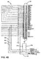
- the printed circuit board 50 includes a plurality of layout tracings 56 (which are schematically shown in Fig. 4) and the various electrical components discussed below.
- connectors 23 and 26 are electrically coupled through the printed circuit board 50 in a similar fashion as if ribbon cable 24 directly connected connectors 23 and 26.
- wires 102, 104 and 106 tap into wires on the printed circuit board 50 that are used to transmit the PERROR, SELECT, and FAULT* signals, respectively.
- Wires 108 and 110 are connected to connector positions A36 of conneczors 23 and 26, respectively.
- all printers using a CENTRONICS parallel port use the PERROR, SELECT and FAULT* signals to transmit information to the computer about the printer state, whether it is a paper jam or other online occurrence.
- the five volt power supply 16 is connected through resistors 57a and 57b to wires 104 and 106, which prevent the light 34 and buzzer 36 from becoming activated if power is applied to the warning device 10 before it is connected to the printer. The light 34 and buzzer 36 can then be activated after the warning device 10 is connected to the printer 22.
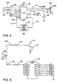
- the printed circuit board 50 includes a clock 58, a one shot timer 60 and a programmable logic device (PLD) 62 or other type of microprocessor device.
- the one shot timer 60 creates a one second delay before the alarm is activated so as to avoid intermittent activation.
- Wires 102, 104, 106 and 108 are connected to the input pins of PLD 62 along with wires 112 and 114 of the clock 58 and the one shot timer 60.
- Wire 110 is connected to an output pin of PLD 62, along with wire 118 of the one shot timer 60 and alarm wire 116.
- Alarm wire 116 is connected to the base of transistor 64, which has its emitter connected to the five volt power supply 16.
- Output wire 119 connects the collector of transistor 64 to the modular female connector jack 32.
- the five volt power supply 16 also supplies power to the PLD 62, the clock 58, transistor 64 and the one shot timer 60.
- the alarm box 14 includes both the piezoelectric buzzer 36 and an LED 34 which are connected in parallel through wires 120 and 122 to male connector jack 30, which connects to female connector jack 32. Switches 38 and 40 are provided in the wires 120 and 122 to the respective buzzer 36 and LED 34. The buzzer 36 or LED 34 can be disabled by setting the respective switches 38 and 40 in an open position as opposed to the normally closed position.
- the SELECT and FAULT* signals are operated at between three to five volts and the PERROR signal operates at between zero to two volts.
- These voltages indicate that the printer is in an operational state and no printing errors exist, such as a paper jam.
- Wires 102, 104 and 106 monitor these voltages.
- the operating voltages of at least one of the SELECT, FAULT* and PERROR lines will change from a high voltage to a low voltage or from a low voltage to a high voltage, respectively, as shown in Fig. 8, which shows all three of these voltages changed.
- the voltages of wires 102, 104 and 106 are measured by the PLD 62 and converted into digital logic, where a corresponding high voltage equals "1" and a corresponding low voltage equals "0". If either the SELECT, FAULT* or PERROR signals change from their normal state to a printer error state, then a small current passes through wire 116 which turns on transistor 64 and allows a current to pass through wire 118 and activate the buzzer 36 and LED 34. The buzzer 36 and LED 34 will become deactivated when the SELECT, FAULT* and PERROR signals return to their normal states, or switches 38 and 40 are opened.
- the warning device 10 is adapted to operate in a normal CENTRONICS mode, where the PERROR, SELECT and FAULT* signals operate in only two states: normal and abnormal (i.e., printer online and printer offline). However, several printers use PERROR, SELECT and FAULT* signals for bidirectional communication in a P1284 mode, whereby the voltage across these wires continually varies between a high state and a low state.
- Connector position A36 of male connector 26 and female connector 23 through which the SELECTIN* signal passes will have a low voltage (zero volts-two volts) if the printer is operating in the CENTRONICS mode, and a high voltage (three volts-five volts) if zhe printer is operating in the P1284 mode.
- Wire 108 connects connector position A36 of connector 23 to the PLD 62. Based upon the voltage of wire 108, the PLD 62 determines if the printer is operating in the P1284 mode. If the PLD 62 determines that is the case, then the PLD 62 ignores the states of PERROR, FAULT* and SELECT so that buzzer 36 or LED 34 cannot be activated.
- a light bulb or LED 66 in the warning device 10 can be provided to indicate when the printer is operating in a P1284 mode.
- the computer 19 is interfaced to the printer 22 through the parallel port female connector 32, this is not necessary for the warning device 10 to operate.
- the computer can be directly interfaced to the printer through the printer serial port as schematically shown in Fig. 9. Also, the computer can be connected to the printer by whatever means, i.e., serial port, local talk, Ethernet or Token Ring network. Hence, a computer does not have to be interfaced with female connector 32 for the warning device to operate.
- the warning device 10 can be incorporated with many printers. It is versatile, in that it is small in size, no software changes need to be made to the printer computer and no hardware changes need to be made to the printer. Due to the modularity of the warning device 10, the interface box 12 can be attached to the printer and the alarm box can be positioned, using the appropriate length of cable, at a desired location remote from the printer.
Landscapes
- Accessory Devices And Overall Control Thereof (AREA)
- Alarm Systems (AREA)
- Injection Moulding Of Plastics Or The Like (AREA)
Claims (15)
- Verfahren zum Feststellen eines Druckerfehlers, wobei der besagte Drucker (22) elektrisch mit einem Computer (19) verbunden ist und wobei der besagte Drucker (22) in elektrischer Weise mit einer modularen Warnvorrichtung (10) verbunden ist,- wobei entweder der besagte Drucker (22) in elektrischer Weise mit der modularen Warnvorrichtung (10) über mindestens einen ersten externen Draht (102, 104, 106) und einen zweiten externen Draht (108, 110), verbunden ist,- oder wobei die Verbindung zwischen dem besagten Drucker (22) und dem besagten Computer (19) ein Kabel (18) umfasst, welches aus einer Vielzahl von Drähten besteht, die mindestens einen ersten (102, 104, 106) und einen zweiten Draht (108, 110) umfasst, und wobei die Signale von dem mindestens ersten Draht und dem besagten zweiten Draht in elektrischer Weise über die modulare Warnvorrichtung (10) abgefragt werden,
wobei das Verfahren die Schritte umfasst:a) Überwachen des oder der elektrischen Zustände des/der ersten Drahtes/Drähte (102, 104, 106) und des zweiten Drahtes (108, 110),b) Bestimmen, über die modulare Warnvorrichtung (10), ob die elektrischen Zustände des/der ersten Drahtes/Drähte (102, 104, 106) einen normalen Zustand oder einen Druckerfehlerzustand anzeigen, undc) Bestimmen, über die modulare Warnvorrichtung, ob der elektrische Zustand des zweiten Drahtes (108, 110) einen normalen Zustand oder einen Übersteuerzustand anzeigt, undd) Aktivieren eines Alarms über die modulare Warnvorrichtung, falls der bestimmte elektrische Zustand des/der ersten Drahtes/Drähte (102, 104, 106) auf einen Druckerfehlerzustand hinweist und der bestimmte elektrische Zustand des zweiten Drahtes (108, 110) in einem normalen Zustand ist, und das Verhindern der Aktivierung des besagten Alarmes, falls der zweite Draht (108, 110) in einem elektrischen Übersteuerzustand ist. - Verfahren zum Feststellen eines Druckerfehlers nach Anspruch 1, weiterhin umfassend das Überwachen des elektrischen Zustandes von mehreren ersten Drähten (102, 104, 106),- Bestimmen, ob der elektrische Zustand von jedem der überwachten ersten Drähte (102, 104, 106) auf einen normalen Zustand oder einen Druckerfehlerzustand hinweist, und- Aktivieren des Alarms, falls irgend einer der bestimmten elektrischen Zustände der überwachten ersten Drähte (102, 104, 106) auf einen Druckerfehlerzustand hinweist und Vermeiden der Aktivierung des besagten Alarms, falls der zweite Draht (108, 110) sich in einem elektrischen Übersteuerzustand befindet.
- Verfahren zum Feststellen eines Druckerfehlers nach Anspruch 1 oder 2, bei dem der normale Zustand ein CENTRONICS-Zustand und der Übersteuerzustand ein P1284-Zustand ist.
- Verfahren zum Feststellen eines Druckerfehlers nach einem der Ansprüche 1 bis 3, bei dem der Drucker einen CENTRONICS-Parallelanschluss umfasst.
- Verfahren zur Feststellung eines Druckerfehlers nach einem der Ansprüche 1 bis 4, bei dem der besagte Alarm mindestens ein Licht (34) oder einen Summer (36) umfasst.
- Vorrichtung zum Feststellen eines Druckerfehlers nach einem Verfahren nach einem der Ansprüche 1 bis 5, wobei ein Drucker (22) in elektrischer Weise mit einem Computer (19) über ein Kabel (18) verbunden ist, welches aus einer Vielzahl von verbindenden Drähten besteht, umfassend:- ein Schnittstellenmodul (12) mit einem Körper, Mittel zum Aufnehmen eines Computerkabels (18), welches aus einer Vielzahl von Drähten besteht, die geeignet sind, von dem Computer (19) aufgenommen und mit dem besagten Körper verbunden zu werden, Mittel zur Aufnahme eines Druckerkabels (24) aus einer Vielzahl von Verbindungsdrähten, die geeignet sind, von dem Drucker aufgenommen und mit dem besagten Körper verbunden zu werden, und Schnittstellendrähte, die mit dem besagten Körper elektrisch mit dem besagten Computerkabel und dem besagten Druckerkabel verbunden sind, wobei der Computer in elektrischer Weise mit dem Drucker über das besagte Computerkabel, das besagte Druckerkabel und die besagten Schnittestellenverbindungsdrähte verbunden sind,- einen oder mehrere Abfragedrähte (102, 104, 106), die mit den besagten Schnittstellendrähte verbunden und mit dem Körper befestigt sind,- Berechnungsmittel (50) zum Empfang von elektrischen Signalen von dem besagten einen oder mehreren Abfragedrähten, wobei die besagten Berechnungsmittel den Druckerzustand von den empfangenen elektrischen Signalen bestimmen und ein Aktivierungssignal übertragen, falls der Drucker sich in einem Fehlerzustand befindet,- einen Alarm (14), der in elektrischer Weise mit den besagten Berechnungsmitteln verbunden ist, wobei der besagte Alarm durch das Aktivierungssignal aktiviert wird, wobei der besagte Alarm und die besagten Berechnungsmittel durch eine elektrische Quelle (16) ausserhalb des besagten Computerkabels und des besagten Druckerkabels gespeist werden, und- Übersteuerdrähte (108, 110), die in elektrischer Weise mit den besagten Berechnungsmittel (50) verbunden und geeignet sind, mit dem Drucker verbunden zu werden, wobei ein elektrisches Übersteuersignal, welches durch die besagten Übersteuerdrähte hindurch geht, die besagten Berechnungsmittel von der Abgabe eines Aktivierungssignals abhält.
- Vorrichtung nach Anspruch 6, bei dem die besagten Verbindungsdrähte angeordnet sind, um mit einem CENTRONICS-Parallelanschluss verbunden zu werden.
- Vorrichtung nach Anspruch 6 oder 7, wobei der besagte Alarm einen hörbaren Alarm und eine Lichtquelle umfasst, die beide elektrisch mit den besagten Berechnungsmitteln verbunden und durch das Aktivierungssignal aktiviert werden.
- Vorrichtung nach einem der Ansprüche 6, 7 oder 8, wobei die zwei Ausschaltschalter (38, 40) in elektrischer Weise jeweils mit dem besagten hörbaren Alarm und der besagten Lichtquelle verbunden sind.
- Vorrichtung nach einem der Ansprüche 6 bis 9, wobei die besagten Verbindungsdrähte mit den Parallelanschlussverbinders verbunden sind.
- Vorrichtung nach einem der Ansprüche 6 bis 10, bei der die besagten Berechnungsmittel in elektrischer Weise mit einem Transistor verbunden sind und der besagte Alarm in elektrischer Weise mit dem besagten Transistor verbunden ist.
- Vorrichtung nach einem der Ansprüche 6 bis 11, bei der die besagten Berechnungsmittel eine programmierbare Logikeinrichtung ist.
- Druckersystem zum Feststellen eines Druckerfehlers nach einem Verfahren nach einem der Ansprüche 1 bis 5, umfassend:- einen Computer (19) mit einem parallelen Computeranschluss,- ein Computerkabel (18), welches aus einer Vielzahl von Drähten besteht, die in elektrischer Weise mit dem besagten parallelen Computeranschluss verbunden sind,- ein Schnittstellenmodul (12) mit einem Körper, einer Vielzahl von Schnittstellendrähten und einem oder mehreren Abfragedrähten (102, 104, 106), wobei das besagte Computerkabel (18) in elektrischer Weise mit dem besagten Körper verbunden ist, wobei die besagte Vielzahl von Schnittstellendrähten in elektrischer Weise mit dem besagten Computerkabel verbunden sind und die besagten Abfragedrähte mit den besagten Schnittstellendrähten verbunden sind,- einen Drucker (22) mit einem parallelen Druckeranschluss,- ein Druckerkabel (24), welches aus einer Vielzahl von Drähten besteht, die in elektrischer Weise mit dem besagten parallelen Druckeranschluss verbunden sind und in elektrischer Weise mit den besagten Schnittstellendrähten verbunden sind, so dass der besagte parallele Computeranschluss in elektrischer Weise mit dem besagten parallelen Printeranschluss verbunden ist,- Berechnungsmittel (50) zum Empfang von elektrischen Signalen von den besagten Abfragedrähten, wobei die besagten Berechnungsmittel den Druckerzustand aus dem besagten elektrischen Signal feststellen und ein Aktivierungssignal übermitteln, falls der Drucker sich in einem Fehlerzustand befindet, wobei die besagten Berechnungsmittel mit dem besagten Körper verbunden sind, wobei ein Alarm (14) in elektrischer Weise mit den besagten Berechnungsmitteln (50) verbunden ist, wobei der besagte Alarm durch das Aktivierungssignal aktiviert wird, wobei der besagte Alarm und die besagten Berechnungsmittel durch eine elektrische Quelle (16) gespeist werden, die extern des besagten Computerkabels und des besagten Druckerkabels ist, und- Übersteuerdrähte (108, 110), die in elektrischer Weise - mit den besagten Berechnungsmitteln verbunden sind und geeignet sind, mit dem Drucker verbunden zu werden, wobei ein elektrisches Übersteuersignal durch die besagten Übersteuerdrähte verhindert, dass die besagten Berechnungsmittel ein Aktivierungssignal abgeben.
- Druckersystem nach Anspruch 13, bei dem die elektrische Quelle (16) eine Spannungsversorgung (16) ist, die in elektrischer Weise mit dem besagten Alarm und dem besagten Schnittstellenmodul verbunden ist, wobei die besagte Spannungsversorgung und die besagte Schnittstelle und der besagte Alarm modular sind.
- Druckersystem nach Anspruch 13 oder 14, wobei der besagte Computer einen parallelen CENTRONICS-Anschluss umfasst, der in elektrischer Weise mit dem besagten Drucker durch das besagte Schnittstellenmodul verbunden ist.
Applications Claiming Priority (3)
| Application Number | Priority Date | Filing Date | Title |
|---|---|---|---|
| US08/656,890 US5717384A (en) | 1996-05-30 | 1996-05-30 | Warning device for printers |
| US656890 | 1996-05-30 | ||
| PCT/US1997/009209 WO1997045821A1 (en) | 1996-05-30 | 1997-05-29 | Warning device for printers |
Publications (3)
| Publication Number | Publication Date |
|---|---|
| EP0901673A1 EP0901673A1 (de) | 1999-03-17 |
| EP0901673A4 EP0901673A4 (de) | 1999-11-17 |
| EP0901673B1 true EP0901673B1 (de) | 2006-01-04 |
Family
ID=24634996
Family Applications (1)
| Application Number | Title | Priority Date | Filing Date |
|---|---|---|---|
| EP97927844A Expired - Lifetime EP0901673B1 (de) | 1996-05-30 | 1997-05-29 | Warnungsvorrichtung für druckmaschinen |
Country Status (8)
| Country | Link |
|---|---|
| US (1) | US5717384A (de) |
| EP (1) | EP0901673B1 (de) |
| JP (1) | JP3962843B2 (de) |
| AT (1) | ATE315264T1 (de) |
| DE (1) | DE69735061T2 (de) |
| DK (1) | DK0901673T3 (de) |
| ES (1) | ES2256889T3 (de) |
| WO (1) | WO1997045821A1 (de) |
Families Citing this family (3)
| Publication number | Priority date | Publication date | Assignee | Title |
|---|---|---|---|---|
| GB2361792A (en) * | 2000-04-25 | 2001-10-31 | Hara Kenneth O | In-line interface box for alarm system |
| JP4805992B2 (ja) * | 2008-09-30 | 2011-11-02 | 株式会社沖データ | 画像処理装置 |
| US9176694B2 (en) | 2010-10-26 | 2015-11-03 | Xerox Corporation | Printer with audible signal |
Family Cites Families (18)
| Publication number | Priority date | Publication date | Assignee | Title |
|---|---|---|---|---|
| US3701019A (en) * | 1970-03-25 | 1972-10-24 | Signatron | Alarm system using coded signalling |
| US4255669A (en) * | 1979-09-17 | 1981-03-10 | Gte Laboratories Incorporated | Sensing apparatus |
| JPS58181193A (ja) * | 1982-04-16 | 1983-10-22 | 株式会社日立製作所 | 表示駆動装置 |
| US4682875A (en) * | 1982-07-21 | 1987-07-28 | Canon Kabushiki Kaisha | Image forming system having external signal generating means |
| US4621343A (en) * | 1982-08-27 | 1986-11-04 | Hitachi Koki Company, Limited | Circuit arrangement for detecting error in print control apparatus |
| JPS6378298A (ja) * | 1986-09-22 | 1988-04-08 | シャープ株式会社 | 機器の異常警報装置 |
| JPH02131980A (ja) * | 1988-11-14 | 1990-05-21 | Asahi Optical Co Ltd | レーザープリンター |
| JP2780312B2 (ja) * | 1989-03-13 | 1998-07-30 | 日本電気株式会社 | 異常検出回路 |
| US4996487A (en) * | 1989-04-24 | 1991-02-26 | International Business Machines Corporation | Apparatus for detecting failure of thermal heaters in ink jet printers |
| US5081627A (en) * | 1989-07-05 | 1992-01-14 | Casat Technologies, Inc. | Status and activity monitor for contention type local area networks |
| JPH03146360A (ja) * | 1989-10-31 | 1991-06-21 | Kanzaki Paper Mfg Co Ltd | サーマルヘッド断線検知回路 |
| US5008655A (en) * | 1989-11-20 | 1991-04-16 | Schlesinger Robert A | Visual alarm device interconnectable to existing monitoring circuitry |
| JPH03262099A (ja) * | 1990-03-13 | 1991-11-21 | Oki Electric Ind Co Ltd | 異常検出システム |
| JPH0494956A (ja) * | 1990-08-13 | 1992-03-27 | Brother Ind Ltd | 記録装置用表示装置 |
| US5142269A (en) * | 1991-04-01 | 1992-08-25 | Charles T. Rush | Electronic component theft sensor and security system |
| JPH04327953A (ja) * | 1991-04-30 | 1992-11-17 | Oki Electric Ind Co Ltd | アラーム制御方法 |
| JP2759011B2 (ja) * | 1991-10-28 | 1998-05-28 | 株式会社東芝 | 画像形成装置 |
| US5250986A (en) * | 1992-05-06 | 1993-10-05 | Hewlett-Packard Company | Peripheral unit control panel with smart key |
-
1996
- 1996-05-30 US US08/656,890 patent/US5717384A/en not_active Expired - Lifetime
-
1997
- 1997-05-29 AT AT97927844T patent/ATE315264T1/de not_active IP Right Cessation
- 1997-05-29 DE DE69735061T patent/DE69735061T2/de not_active Expired - Lifetime
- 1997-05-29 ES ES97927844T patent/ES2256889T3/es not_active Expired - Lifetime
- 1997-05-29 WO PCT/US1997/009209 patent/WO1997045821A1/en not_active Ceased
- 1997-05-29 DK DK97927844T patent/DK0901673T3/da active
- 1997-05-29 EP EP97927844A patent/EP0901673B1/de not_active Expired - Lifetime
- 1997-05-29 JP JP54295697A patent/JP3962843B2/ja not_active Expired - Fee Related
Also Published As
| Publication number | Publication date |
|---|---|
| JP3962843B2 (ja) | 2007-08-22 |
| DE69735061D1 (de) | 2006-03-30 |
| EP0901673A4 (de) | 1999-11-17 |
| DE69735061T2 (de) | 2006-08-10 |
| DK0901673T3 (da) | 2006-04-03 |
| WO1997045821A1 (en) | 1997-12-04 |
| JP2000511480A (ja) | 2000-09-05 |
| ES2256889T3 (es) | 2006-07-16 |
| EP0901673A1 (de) | 1999-03-17 |
| US5717384A (en) | 1998-02-10 |
| ATE315264T1 (de) | 2006-02-15 |
Similar Documents
| Publication | Publication Date | Title |
|---|---|---|
| EP0527599B1 (de) | Elektrischer Verbinder | |
| US5406260A (en) | Network security system for detecting removal of electronic equipment | |
| US4748426A (en) | Active termination circuit for computer interface use | |
| EP0836742B1 (de) | Rekonfigurierbarer verbinder | |
| US5488307A (en) | Sensor interface method and apparatus | |
| US7039744B2 (en) | Movable lead access member for handheld field maintenance tool | |
| EP0901673B1 (de) | Warnungsvorrichtung für druckmaschinen | |
| US5090830A (en) | Printer having single connector for parallel and serial interfaces | |
| CA2255959C (en) | Warning device for printers | |
| JP7418097B2 (ja) | 情報処理装置、およびその制御方法 | |
| KR20000067984A (ko) | 해상도를 감지하는 컴퓨터 연결 어댑터 | |
| US4502113A (en) | System for checking an electrical connection between a computer and a printer | |
| KR102792161B1 (ko) | 디지털입력신호 표시장치 | |
| KR950007838Y1 (ko) | 데이타 충돌 표시 장치 | |
| JPH0675901A (ja) | 端末機器制御装置 | |
| KR100424002B1 (ko) | 프린터의용지부족경고방법 | |
| KR100222926B1 (ko) | 수치제어장치 및 수치제어장치의 통신상태 검사방법 | |
| JP2508580B2 (ja) | バス終端制御システム | |
| JP2599199B2 (ja) | 通信回路 | |
| JPH05265616A (ja) | バス接続方法 | |
| JPH06149687A (ja) | Scsi終端抵抗検出回路 | |
| JP2001125681A (ja) | 電子機器 | |
| JPS63167595A (ja) | 二重化コミニユケ−タ | |
| JPH10250195A (ja) | 周辺装置 | |
| JPH11207000A (ja) | 電源供給制御装置および動作確認装置 |
Legal Events
| Date | Code | Title | Description |
|---|---|---|---|
| PUAI | Public reference made under article 153(3) epc to a published international application that has entered the european phase |
Free format text: ORIGINAL CODE: 0009012 |
|
| 17P | Request for examination filed |
Effective date: 19981229 |
|
| AK | Designated contracting states |
Kind code of ref document: A1 Designated state(s): AT BE CH DE DK ES FI FR GB GR IE IT LI LU MC NL PT SE |
|
| A4 | Supplementary search report drawn up and despatched |
Effective date: 19991004 |
|
| AK | Designated contracting states |
Kind code of ref document: A4 Designated state(s): AT BE CH DE DK ES FI FR GB GR IE IT LI LU MC NL PT SE |
|
| RIC1 | Information provided on ipc code assigned before grant |
Free format text: 6G 08B 21/00 A, 6B 41J 29/393 B |
|
| 17Q | First examination report despatched |
Effective date: 20021108 |
|
| GRAP | Despatch of communication of intention to grant a patent |
Free format text: ORIGINAL CODE: EPIDOSNIGR1 |
|
| RIC1 | Information provided on ipc code assigned before grant |
Ipc: 7B 41J 29/46 B Ipc: 7B 41J 29/393 B Ipc: 7G 08B 21/00 A |
|
| RAP1 | Party data changed (applicant data changed or rights of an application transferred) |
Owner name: KONICA MINOLTA PRINTING SOLUTIONS U.S.A. |
|
| GRAS | Grant fee paid |
Free format text: ORIGINAL CODE: EPIDOSNIGR3 |
|
| GRAA | (expected) grant |
Free format text: ORIGINAL CODE: 0009210 |
|
| AK | Designated contracting states |
Kind code of ref document: B1 Designated state(s): AT BE CH DE DK ES FI FR GB GR IE IT LI LU MC NL PT SE |
|
| REG | Reference to a national code |
Ref country code: GB Ref legal event code: FG4D |
|
| REG | Reference to a national code |
Ref country code: CH Ref legal event code: NV Representative=s name: ISLER & PEDRAZZINI AG Ref country code: CH Ref legal event code: EP |
|
| REG | Reference to a national code |
Ref country code: IE Ref legal event code: FG4D |
|
| REG | Reference to a national code |
Ref country code: SE Ref legal event code: TRGR |
|
| REF | Corresponds to: |
Ref document number: 69735061 Country of ref document: DE Date of ref document: 20060330 Kind code of ref document: P |
|
| REG | Reference to a national code |
Ref country code: DK Ref legal event code: T3 |
|
| PGFP | Annual fee paid to national office [announced via postgrant information from national office to epo] |
Ref country code: MC Payment date: 20060426 Year of fee payment: 10 |
|
| PGFP | Annual fee paid to national office [announced via postgrant information from national office to epo] |
Ref country code: NL Payment date: 20060503 Year of fee payment: 10 |
|
| PGFP | Annual fee paid to national office [announced via postgrant information from national office to epo] |
Ref country code: SE Payment date: 20060505 Year of fee payment: 10 |
|
| PGFP | Annual fee paid to national office [announced via postgrant information from national office to epo] |
Ref country code: AT Payment date: 20060511 Year of fee payment: 10 |
|
| PGFP | Annual fee paid to national office [announced via postgrant information from national office to epo] |
Ref country code: FI Payment date: 20060512 Year of fee payment: 10 |
|
| PGFP | Annual fee paid to national office [announced via postgrant information from national office to epo] |
Ref country code: IE Payment date: 20060515 Year of fee payment: 10 |
|
| PGFP | Annual fee paid to national office [announced via postgrant information from national office to epo] |
Ref country code: DK Payment date: 20060516 Year of fee payment: 10 |
|
| PGFP | Annual fee paid to national office [announced via postgrant information from national office to epo] |
Ref country code: PT Payment date: 20060526 Year of fee payment: 10 |
|
| PGFP | Annual fee paid to national office [announced via postgrant information from national office to epo] |
Ref country code: CH Payment date: 20060530 Year of fee payment: 10 |
|
| PGFP | Annual fee paid to national office [announced via postgrant information from national office to epo] |
Ref country code: IT Payment date: 20060531 Year of fee payment: 10 |
|
| PGFP | Annual fee paid to national office [announced via postgrant information from national office to epo] |
Ref country code: ES Payment date: 20060621 Year of fee payment: 10 |
|
| PGFP | Annual fee paid to national office [announced via postgrant information from national office to epo] |
Ref country code: BE Payment date: 20060711 Year of fee payment: 10 |
|
| REG | Reference to a national code |
Ref country code: ES Ref legal event code: FG2A Ref document number: 2256889 Country of ref document: ES Kind code of ref document: T3 |
|
| ET | Fr: translation filed | ||
| PLBE | No opposition filed within time limit |
Free format text: ORIGINAL CODE: 0009261 |
|
| STAA | Information on the status of an ep patent application or granted ep patent |
Free format text: STATUS: NO OPPOSITION FILED WITHIN TIME LIMIT |
|
| 26N | No opposition filed |
Effective date: 20061005 |
|
| REG | Reference to a national code |
Ref country code: CH Ref legal event code: PCAR Free format text: ISLER & PEDRAZZINI AG;POSTFACH 1772;8027 ZUERICH (CH) |
|
| REG | Reference to a national code |
Ref country code: PT Ref legal event code: MM4A Free format text: LAPSE DUE TO NON-PAYMENT OF FEES Effective date: 20071129 |
|
| BERE | Be: lapsed |
Owner name: *KONICA MINOLTA PRINTING SOLUTIONS U.S.A. INC. Effective date: 20070531 |
|
| EUG | Se: european patent has lapsed | ||
| REG | Reference to a national code |
Ref country code: CH Ref legal event code: PL |
|
| REG | Reference to a national code |
Ref country code: DK Ref legal event code: EBP |
|
| PG25 | Lapsed in a contracting state [announced via postgrant information from national office to epo] |
Ref country code: PT Free format text: LAPSE BECAUSE OF NON-PAYMENT OF DUE FEES Effective date: 20071129 Ref country code: NL Free format text: LAPSE BECAUSE OF NON-PAYMENT OF DUE FEES Effective date: 20071201 Ref country code: MC Free format text: LAPSE BECAUSE OF NON-PAYMENT OF DUE FEES Effective date: 20070531 Ref country code: FI Free format text: LAPSE BECAUSE OF NON-PAYMENT OF DUE FEES Effective date: 20070529 |
|
| NLV4 | Nl: lapsed or anulled due to non-payment of the annual fee |
Effective date: 20071201 |
|
| PG25 | Lapsed in a contracting state [announced via postgrant information from national office to epo] |
Ref country code: CH Free format text: LAPSE BECAUSE OF NON-PAYMENT OF DUE FEES Effective date: 20070531 Ref country code: LI Free format text: LAPSE BECAUSE OF NON-PAYMENT OF DUE FEES Effective date: 20070531 Ref country code: AT Free format text: LAPSE BECAUSE OF NON-PAYMENT OF DUE FEES Effective date: 20070529 |
|
| PG25 | Lapsed in a contracting state [announced via postgrant information from national office to epo] |
Ref country code: BE Free format text: LAPSE BECAUSE OF NON-PAYMENT OF DUE FEES Effective date: 20070531 |
|
| PG25 | Lapsed in a contracting state [announced via postgrant information from national office to epo] |
Ref country code: GR Free format text: LAPSE BECAUSE OF FAILURE TO SUBMIT A TRANSLATION OF THE DESCRIPTION OR TO PAY THE FEE WITHIN THE PRESCRIBED TIME-LIMIT Effective date: 20060405 Ref country code: DK Free format text: LAPSE BECAUSE OF NON-PAYMENT OF DUE FEES Effective date: 20070531 |
|
| PG25 | Lapsed in a contracting state [announced via postgrant information from national office to epo] |
Ref country code: IE Free format text: LAPSE BECAUSE OF NON-PAYMENT OF DUE FEES Effective date: 20070529 |
|
| PG25 | Lapsed in a contracting state [announced via postgrant information from national office to epo] |
Ref country code: SE Free format text: LAPSE BECAUSE OF NON-PAYMENT OF DUE FEES Effective date: 20070530 |
|
| PG25 | Lapsed in a contracting state [announced via postgrant information from national office to epo] |
Ref country code: LU Free format text: LAPSE BECAUSE OF NON-PAYMENT OF DUE FEES Effective date: 20060529 |
|
| REG | Reference to a national code |
Ref country code: ES Ref legal event code: FD2A Effective date: 20070530 |
|
| PG25 | Lapsed in a contracting state [announced via postgrant information from national office to epo] |
Ref country code: ES Free format text: LAPSE BECAUSE OF NON-PAYMENT OF DUE FEES Effective date: 20070530 |
|
| PG25 | Lapsed in a contracting state [announced via postgrant information from national office to epo] |
Ref country code: IT Free format text: LAPSE BECAUSE OF NON-PAYMENT OF DUE FEES Effective date: 20070529 |
|
| REG | Reference to a national code |
Ref country code: FR Ref legal event code: PLFP Year of fee payment: 19 |
|
| PGFP | Annual fee paid to national office [announced via postgrant information from national office to epo] |
Ref country code: GB Payment date: 20150527 Year of fee payment: 19 Ref country code: DE Payment date: 20150527 Year of fee payment: 19 |
|
| PGFP | Annual fee paid to national office [announced via postgrant information from national office to epo] |
Ref country code: FR Payment date: 20150508 Year of fee payment: 19 |
|
| REG | Reference to a national code |
Ref country code: DE Ref legal event code: R119 Ref document number: 69735061 Country of ref document: DE |
|
| GBPC | Gb: european patent ceased through non-payment of renewal fee |
Effective date: 20160529 |
|
| REG | Reference to a national code |
Ref country code: FR Ref legal event code: ST Effective date: 20170131 |
|
| PG25 | Lapsed in a contracting state [announced via postgrant information from national office to epo] |
Ref country code: DE Free format text: LAPSE BECAUSE OF NON-PAYMENT OF DUE FEES Effective date: 20161201 Ref country code: FR Free format text: LAPSE BECAUSE OF NON-PAYMENT OF DUE FEES Effective date: 20160531 |
|
| PG25 | Lapsed in a contracting state [announced via postgrant information from national office to epo] |
Ref country code: GB Free format text: LAPSE BECAUSE OF NON-PAYMENT OF DUE FEES Effective date: 20160529 |