EP0901353B1 - Extenseur - Google Patents
Extenseur Download PDFInfo
- Publication number
- EP0901353B1 EP0901353B1 EP97920561A EP97920561A EP0901353B1 EP 0901353 B1 EP0901353 B1 EP 0901353B1 EP 97920561 A EP97920561 A EP 97920561A EP 97920561 A EP97920561 A EP 97920561A EP 0901353 B1 EP0901353 B1 EP 0901353B1
- Authority
- EP
- European Patent Office
- Prior art keywords
- stent
- stent according
- weave
- filaments
- tube
- Prior art date
- Legal status (The legal status is an assumption and is not a legal conclusion. Google has not performed a legal analysis and makes no representation as to the accuracy of the status listed.)
- Expired - Lifetime
Links
Images
Classifications
-
- A—HUMAN NECESSITIES
- A61—MEDICAL OR VETERINARY SCIENCE; HYGIENE
- A61F—FILTERS IMPLANTABLE INTO BLOOD VESSELS; PROSTHESES; DEVICES PROVIDING PATENCY TO, OR PREVENTING COLLAPSING OF, TUBULAR STRUCTURES OF THE BODY, e.g. STENTS; ORTHOPAEDIC, NURSING OR CONTRACEPTIVE DEVICES; FOMENTATION; TREATMENT OR PROTECTION OF EYES OR EARS; BANDAGES, DRESSINGS OR ABSORBENT PADS; FIRST-AID KITS
- A61F2/00—Filters implantable into blood vessels; Prostheses, i.e. artificial substitutes or replacements for parts of the body; Appliances for connecting them with the body; Devices providing patency to, or preventing collapsing of, tubular structures of the body, e.g. stents
- A61F2/82—Devices providing patency to, or preventing collapsing of, tubular structures of the body, e.g. stents
- A61F2/86—Stents in a form characterised by the wire-like elements; Stents in the form characterised by a net-like or mesh-like structure
- A61F2/88—Stents in a form characterised by the wire-like elements; Stents in the form characterised by a net-like or mesh-like structure the wire-like elements formed as helical or spiral coils
-
- A—HUMAN NECESSITIES
- A61—MEDICAL OR VETERINARY SCIENCE; HYGIENE
- A61F—FILTERS IMPLANTABLE INTO BLOOD VESSELS; PROSTHESES; DEVICES PROVIDING PATENCY TO, OR PREVENTING COLLAPSING OF, TUBULAR STRUCTURES OF THE BODY, e.g. STENTS; ORTHOPAEDIC, NURSING OR CONTRACEPTIVE DEVICES; FOMENTATION; TREATMENT OR PROTECTION OF EYES OR EARS; BANDAGES, DRESSINGS OR ABSORBENT PADS; FIRST-AID KITS
- A61F2/00—Filters implantable into blood vessels; Prostheses, i.e. artificial substitutes or replacements for parts of the body; Appliances for connecting them with the body; Devices providing patency to, or preventing collapsing of, tubular structures of the body, e.g. stents
- A61F2/95—Instruments specially adapted for placement or removal of stents or stent-grafts
-
- A—HUMAN NECESSITIES
- A61—MEDICAL OR VETERINARY SCIENCE; HYGIENE
- A61F—FILTERS IMPLANTABLE INTO BLOOD VESSELS; PROSTHESES; DEVICES PROVIDING PATENCY TO, OR PREVENTING COLLAPSING OF, TUBULAR STRUCTURES OF THE BODY, e.g. STENTS; ORTHOPAEDIC, NURSING OR CONTRACEPTIVE DEVICES; FOMENTATION; TREATMENT OR PROTECTION OF EYES OR EARS; BANDAGES, DRESSINGS OR ABSORBENT PADS; FIRST-AID KITS
- A61F2210/00—Particular material properties of prostheses classified in groups A61F2/00 - A61F2/26 or A61F2/82 or A61F9/00 or A61F11/00 or subgroups thereof
- A61F2210/0076—Particular material properties of prostheses classified in groups A61F2/00 - A61F2/26 or A61F2/82 or A61F9/00 or A61F11/00 or subgroups thereof multilayered, e.g. laminated structures
Definitions
- the invention relates to a stent for splinting and / or to keep a cavity open, in particular a hollow organ, how this stent is defined in the preamble of claim 1 becomes.
- a stent is e.g. from the publication WO 95/05132 known.
- DE 1766921 describes a further stent arrangement for splinting or described for keeping a hollow organ open.
- the well-known The arrangement has a tubular and filament self-expanding network consisting of a variety of interwoven filaments.
- DE 1766921 is the stent as an armored one Hose formed, the net inside the hose is firmly embedded. If the hose is made of a tissue-friendly Material, for example made of a plastic, is produced, there is a stent device for Splinting or suitable for keeping a hollow organ open is. Because the net is completely inside the hose wall is embedded, the outer surface of the hose has a smooth surface, which can be gentle on the tissue, if the hose is made of a tissue-friendly material is, but possibly against one given position within the hollow organ can move.
- Forming the stent according to the invention as a composite between three components with an inner tube, one arranged on it closely arranged tubular braid and a coating arranged on the outer surface of the hose ensures a stent that is not only inexpensive to manufacture, but also a gentle one and secure placement within, for example, a hollow organ enables.
- the outer coating serves to ensure that To fix braid on the outer surface of the hose, the restoring forces (expansion of the stent from a Preloaded elongated stent of smaller diameter into a state of stent with a larger one Diameter and the associated larger lumens) a combination of the elastic properties of the Hose in connection with the braid can be determined.
- the Coating is designed such that a structured Surface of the stent results from the structure of the braid is shaped. That way, unlike the conventional stent, the stent according to the invention a textured surface that provides a secure grip guaranteed within the hollow organ.
- the material of the stent in particular the material of the braid, the restoring forces of the stent can be adjusted become. In this way, it becomes a less expensive one Stent created, which nevertheless has a safe placement within guaranteed a hollow organ.
- the coating is kept sufficiently thin so that the structure of the Filaments to an arched in individual surface sections Surface of the stent leads. This structured surface serves to improve the stent within a hollow organ secured and permanently held in a stable position can.
- the Filaments a round cross-section. This measure has the Advantage that conventional wire material as a braid Filaments can be used.
- the simple one Structuring through a filament with a round Cross-section sufficient to give the stent an embossed surface structure to rent.
- the filaments are polyester, kevlar (a registered trademark), Include glass fibers, and / or metal or from these materials are made.
- Polyester has: the advantage that it as a known material with good processing properties is available and is suitable for a stable bond with the hose and the coating.
- the material of a filament for example polyester or kevlar (a registered trademark)
- Kevlar for example has stiffer material properties than polyester and serves to create a stent that has greater restoring forces having.
- the possibility of restoring forces setting is expanded by the use of glass fibers.
- Metal filaments not only have the property that they ensure particularly strongly reinforced stent structures, but also that the placement and location of the stent can be determined on the basis of X-ray examinations can.
- the filaments are a mixture of glass fibers and metal. This measure has the advantage that the restoring forces are set can be, and that at the same time the placement of the stent can be checked by X-rays.
- the filaments are radiopaque are trained. This has the advantage that regardless of whether the restoring forces by, for example Polyester, Kevlar (a registered trademark) or metal are given to it anyway it is possible to place the stent by X-rays to control.
- this embodiment is metal powder or are metal parts, for example Tungsten, contained in the hose or in the coating.
- This measure has the advantage that the stent is based on X-ray examinations not only thereby “visible" the filaments are, for example, made of a metal manufactured, but also based on the embedded in the stent Metal parts have improved X-ray tightness is achieved. In this way, by choosing the filament material the restoring force of the stent into an expanded one Final state to be influenced, and regardless is the placement of the stent using X-rays controlled possible.
- the hose and / or the Coating contains or contain silicone. This has the advantage that silicone is a particularly easy to process Material is that which is additionally good tissue-compatible Has properties.
- the filaments are firmly fixed, protected Have ends. This has the advantage that the filament ends not damage to the tissue of a hollow organ can trigger, and that structural stability of the stent is improved in the end regions.
- the braid cannot be shield-like in the end area bulge outside.
- the neighboring ones Filament ends with each other through a cover cap connected.
- This cover cap can be tubular or envelope-like be designed. This has the advantage that a relatively simple mechanical construction, namely the cover cap, for reliable protection and localization of the filament ends.
- Another form of this training is the neighboring one Filament ends in a common filament tube captured.
- the hose protects the filament ends and holds the ends of at least two filaments together.
- the crossing points at the ends can be done using for example, a silk thread knotted or wrapped become.
- the combination of the inner tube and the cover cap offers the advantage that the ends are stretched of the stent. It is also possible for better Detection of the stent ends when the stent is in the body mark the ends in color.
- the inside surface of the Stents can be structured so that they are good and durable Wetting of fluids and / or cell tissue possible is.
- the hose preferably has one over the filament ends trained inside out. This has the advantage that the Hose and filament ends in combination to catch Lead filament ends without additional material connections have to be manufactured.
- the stent has the embossed one structured outer surface protruding elevations on.
- the elevations can be anywhere on the outer peripheral surface of the stent and have the effect that they spread, get caught and / or or press into it and thereby the location of a stent secure additionally.
- the surveys are in a further embodiment of the invention formed by free ends of filament pieces that at least in sections next to or parallel to the braid forming filaments.
- This second filament thread that the Do not influence the braid structure or the braid stability must be cut according to the desired section lengths and the resulting free ends are over the outer surface of the stent protrudes outward, so that there is an outer surface with numerous hooks, that can cling to an adjacent tissue.
- the elevations are formed by anchors that are elongated in the stents Condition of the stent on the outer surface of the Stents lie flat and with a first end on the outer surface of the stent are fixed and with a free second end in the expanded state of the stent are spaced from the outer surface of the stent.
- anchors can also be retrofitted attached to a structured outer surface of a stent can be.
- the anchors only unfold at the Expansion of the stent and penetrate into the adjacent one Tissue. These lie in the elongated state of a stent Anchor flat on the outer surface of a stent so that the placement of a stent by these anchors is not difficult becomes.
- the filaments that form the braid are different spaced far apart and / or the filaments have a different diameter.
- the braid of a stent is in another embodiment over one in the axial and / or radial direction manufactured different contour shape, so can additionally depending on the axial course of a Stents the restoring force varies within a stent become. Let different forms of a braid also produce themselves via thermal deformation.
- the stent is designed in this way is that he uses an application device in a hollow body can be introduced. This has the advantage that placement of the stent is facilitated and reproducible Methods for placing the stent according to the invention can be worked out.
- the Application device a catching and sliding device, an application sleeve and a cone plug.
- This has the advantage that the stent with this application device not only introduced into a hollow organ, but can also be placed with this device.
- the cone plug serves for easier handling in the application sleeve.
- the Catch and slide device a spread catch basket from a plastic or metal braid. This has the Advantage that the catching and sliding device is able is to safely catch the stent, and after the stent is inside the application sleeve is kept folded, to release again.
- the catching and sliding device is designed and dimensioned such that they enter the lumen the application sleeve can be inserted.
- the catcher basket faces the application sleeve and / or the stent has increased lubricity when in that Mesh of the catcher basket is incorporated a silicone compound (Coating also reduces friction, for example made of Teflon (a registered trademark) or polyethylene). This ensures a safe one and easier removal of the catching and sliding device from the stent captured in it.
- the catching and sliding device has a lumen. This has the advantage that the lumen of the Catch and slide device is suitable via optical Medium observation of stent placement within to ensure a hollow organ.
- the catch and Slider support for the stent if an area of the free end of the pusher into that Stent lumen protrudes.
- Small stent sizes ⁇ 10 mm inner diameter can when sliding out of the application sleeve not be damaged because they are from the interior be supported out.
- An additional use of Lubricant in the outer area of the stent is therefore possible the friction between the inner surface of the application sleeve and the outer surface of the stent is degraded.
- the stent In order to remove the stent from the catcher basket, it is necessary not pull it fully into the application sleeve.
- the stent is placed in the application sleeve with a cone plug fixed and the catcher basket pulled out.
- the supernatant Braid can then be inserted into the application sleeve, e.g. under With the aid of the back of the cone plug gently inserted become. If the cone plug is not used, can this leads to deformations and damage to the stent, especially for sizes smaller than 10 mm inner diameter.
- the combination of safety gear and application sleeve can be designed so that both objects with low Wall thicknesses can be produced.
- the application sleeve has a wall thickness that is so thin that it must be stabilized by the safety gear.
- a procedure for inserting the stent can provide that the stent by means of the conically spreading End of the catching and sliding device in the Lumen of the application sleeve is drawn in using the stent of the cone plug within the lumen of the application sleeve is fixed, the catching and sliding device from separated from the stent and from the lumen of the application sleeve is pulled out, the cone plug from the application sleeve is separated, the catching and pushing device is turned over and pushed back into the lumen of the application sleeve will, optical means through the lumen of the capture and Sliding device can be inserted, the application sleeve is introduced into the hollow body, and by means of the stent the catch and slide device from the application sleeve is placed out in the hollow body.
- the catching and sliding device is not only used for this used to pull the stent into the application sleeve, but also around the stent from the application sleeve into the To push out the hollow organ.
- the catching and sliding device accordingly has an end with a safety gear and a the catching device opposite end to the Push the stent out of the application sleeve into the Hollow organ is formed.
- a method of making a Stents can provide the following steps: the braid becomes close to the outer surface of the hose applied, and then the hose and braid immersed in a liquid, for example silicone. This Liquid solidifies and forms the second coating.
- the free ends of the braid can also be connected to each other be welded and additionally by an adhesive layer to be protected. Does the adhesive layer contain barium sulfate, so the stent ends are radiopaque.
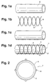
- Fig. la-ld illustrate the structure of the invention Stents 1.
- the stent 1 consists of - as shown in Fig. La is a hose 2 made of an elastic material, one close to the surface of the hose 2 tubular braid 3 - as shown in Fig. 1 b - the is braided from a large number of filaments 5, and one applied to the outer surface of the hose 2 Coating 4 (Fig. 1c).
- 1d shows the stent 1 in assembled condition.
- the inner tube 2 has one smooth inner surface and is due to the composite with the braid 3 consisting of filaments 5, whereby the bond between the tubular braid 3 and the Inner tube 2 is created by means of the coating 4.
- the coating 4 is formed such that by means of the filaments 5 on the outer surface of the Hose 2 distinctive structure through the coating 4 protrudes through to a structured outer surface of the Coating 4 leads.
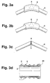
- Fig. 2 shows a schematic cross section or an end view of the stent according to the invention.
- the stent 1 has a structured outer surface, through the filaments provided with a round cross section 5 is pronounced on the outer surface of the hose 2. This is achieved in that the coating 4 is sufficient is thin, the spaces between the filaments 5 are not complete to be filled in, the one embossed by the filaments 5 Structure of the outer surface of the hose 2 simple is sealed by means of the coating 4.
- FIGS. 3a-3d show different ones Ways to hold filament ends 9 together.
- Fig. 3a the ends 9 of the filament 5 by a Cover cap 6 connected to each other protected.
- Fig. 3b the ends 9 of the filaments 5 are each by a common filament tube 7 connected to each other.
- the free ends 9 of the filaments 5 are shown in FIG. 3c a weld 8 assembled and caught.
- Fig. 3d it is alternatively possible to use the free ends of the filaments 5 to capture by an inverting 20 of the inner tube 2.
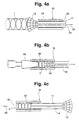
- Fig. 4a and 4b show an application device 10, which is suitable for inserting the stent 1 into a hollow body or to insert into a hollow organ.
- the application device 10 according to FIGS. 4a and 4b consists of an outer application sleeve 15 and an inner catching and sliding device 11.
- the inner catching and sliding device 11 has a spread-out catching device at one end 12 and is on the opposite of the catching device 12 Smooth end.
- the catch and Sliding device 11 provided with a lumen 14.
- Fig. 4a is the stent 1 by means of the spread end of the Catch device 12 in the application sleeve 15 of the application device 10 pulled in the direction of arrow 21.
- the stent 1 is first by means of the spread End 12 of the catching and sliding device 11 in the application sleeve 15 drawn in according to FIG. 4a. After the According to FIG. 4b, stent 1 is completely within the application sleeve 15 is located, the stent 1 by means of the cone plug 16 within the lumen 13 of the application sleeve 15 fixed. A targeted movement of the safety gear 12 in the direction of arrow 21 now releases the stent 1.
- the cone plug 16 is separated from the application sleeve 15 and the catching and sliding device 11 is removed from the application sleeve 15 pulled out, turned over and with her other End pushed back into the application sleeve 15 as shown in FIG. 4c.
- An optical observation of the placement of the Stents 1 are inserted into instruments in a lumen 14 enables.
- the application device 10 is then inside a hollow organ or hollow body, and by moving the catching and sliding device 11 the stent 1 is placed inside the hollow organ.
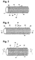
- FIG. 5 shows a stent 50 which consists of a tube 51, a Braid 52 and a coating 53 is formed.
- Next Filament threads 54 from which the braid 52 is made there is a second filament thread next to the threads 54 55, which is interrupted in sections, and its free ends 56 over braid 52 and coating 53 protrude.
- the free ends 56 form barbs for one tissue adjacent to the outer surface of the stent.
- FIG. 6 shows a further embodiment of a stent 60 in the elongated state consisting of a hose 61, a braid 62 and a coating 63 is constructed.
- Anchor 65 On one Surface portion of the outer surface 64 of the stent 60 are Anchor 65 applied.
- the anchors 65 are over a respective one first end 66 stationary with the outer surface 64 of the Stents 60 connected.
- a second end 67 nestles the outer surface 64 of the stent 60.
- the stent 60 is in Direction of arrows 68 elongated.
- the stent 60 of FIG. 6 is in the expanded state shown.
- the stent 60 is expanded in the direction of the arrows 71, so that there is an enlarged lumen 72. While the second ends 67 of the anchors 65 align with the expansion so that they are spaced from the outer surface 64. Via the second ends 67, the armature 65 of the Stents 60 in an adjacent surface or claw.
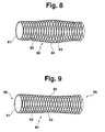
- a stent 80 which also consists of a Hose 81, a braid 82 and a coating 83 is made.
- the shape of the stent 80 is dependent on its axial and radial extension different.
- the Stent 80 has a bulbous contour 84 that stent 80 in the expanded state.
- the bulbous contour 84 is achieved in that the braid 82 over a form is braided, which has this bulbous contour 84.
- the Contour of a shape can be any and is specific to the application vote.
- the bulbous shown in Fig. 8 Contour 64 can also be permanent via thermal deformation can be achieved.
- FIG. 9 shows a further embodiment of a stent 90, who carries a braid 92 on a hose 91, which is of a Coating 93 is covered.
- the Outer contour of the stent 90 over the entire axial extent of the stent 90 has a concave course 94, so that the Stent 90 forms free ends 95, 96, each of which is enlarged Limit lumens in the end region of the stent 90.
- the free ends 95, 96 can still by ring structures on the External surface of the stent 90 are reinforced. These ring structures can also at any section of a Stents regardless of the embodiment of FIG. 9 attached to the outer surface of a stent.
Claims (24)
- Extenseur pour éclisser et/ou maintenir ouvert un organe creux avec un premier revêtement (2) constitué par un matériau élastique, un treillis tubulaire (3) constitué par des filaments (5) reposant étroitement sur la surface externe du premier revêtement (2) et un second revêtement (4) appliqué sur la surface externe du premier revêtement (2), maintenant le treillis (3) sur la surface externe du premier revêtement (2), le diamètre des filaments (5) formant le treillis (3) étant supérieur à l'épaisseur du second revêtement (4), caractérisé en ce que le premier revêtement est sous forme de tuyau souple (2) avec une surface interne lisse sur lequel repose le treillis tubulaire (3), et en ce que le second revêtement est appliqué sur le tuyau souple (2) par immersion dans un liquide sous forme d'un revêtement (4) qui se solidifie et qui forme une surface externe structurée gaufrée par le treillis (3).
- Extenseur selon la revendication 1, caractérisé en ce que le treillis (3) est autoexpansible.
- Extenseur selon l'une des revendications précédentes, caractérisé en ce que les filaments (5) comportent une section droite ronde.
- Extenseur selon l'une des revendications précédentes, caractérisé en ce que les filaments (5) contiennent du polyester, du Kevlar, des fibres de verre et/ou un métal ou sont constitués par ces matériaux.
- Extenseur selon l'une des revendications précédentes, caractérisé en ce que les filaments (5) sont opaques aux rayons X.
- Extenseur selon l'une des revendications 1 à 5, caractérisé en ce qu'une poudre métallique ou des parties métalliques, par exemple du tungstène, sont contenues dans le tuyau souple (2) ou dans le revêtement (4).
- Extenseur selon l'une des revendications précédentes, caractérisé en ce que le tuyau souple (2) et/ou le revêtement (4) qui se solidifie contiennent du silicone ou sont constitués par ce matériau.
- Extenseur selon l'une des revendications précédentes, caractérisé en ce que les filaments (5) comportent des extrémités (9) fixées solidement, en particulier des extrémités (9) protégées.
- Extenseur selon la revendication 8, caractérisé en ce que les extrémités de filaments (9) voisines sont reliées entre elles par paires.
- Extenseur selon la revendication 9, caractérisé en ce que les extrémités de filaments voisines (9) sont reliées entre elles par un capuchon de recouvrement (6).
- Extenseur selon la revendication 9, caractérisé en ce que les extrémités de filaments voisines (9) sont reçues dans un tuyau souple de filaments (7) commun.
- Extenseur selon la revendication 9, caractérisé en ce que les extrémités de filaments voisines (9) sont soudées (8), par exemple par soudage à ultrasons.
- Extenseur selon l'une des revendications 1 à 12, caractérisé en ce que le tuyau souple (2) comporte un retroussis (20) formé au-dessus des extrémités des filaments.
- Extenseur selon l'une des revendications 1 à 13, caractérisé en ce que l'extenseur (50 ; 60 ; 80) comporte des protubérances (56 ; 65 ; 84 ; 95, 96) qui font saillie au-dessus de la surface externe structurée gaufrée.
- Extenseur selon la revendication 14, caractérisé en ce que les protubérances sont formées par des extrémités libres (56) de parties de filaments qui s'étendent au moins par segments à côté de ou parallèlement aux fils de filaments (54) formant le treillis (52).
- Extenseur selon la revendication 14 ou 15, caractérisé en ce que les protubérances sont formées par des ancres (65) qui, à l'état allongé de l'extenseur (60), reposent à plat sur la surface externe (64) de l'extenseur (60) et sont fixées de manière fixe en position par une première extrémité (66) sur la surface externe (64) de l'extenseur (60) et sont distantes de la surface externe (64) de l'extenseur (60) par une seconde extrémité libre (67) à l'état expansé de l'extenseur (60).
- Extenseur selon l'une des revendications 1 à 16, caractérisé en ce que les fils de filaments formant le treillis (52 ; 62 ; 82 ; 92) sont à des distances variables les uns des autres et/ou comportent un diamètre variable.
- Extenseur selon l'une des revendications 1 à 17, caractérisé en ce que le treillis (82 ; 92) est formé sur une forme présentant un contour variable en direction axiale et/ou radiale.
- Extenseur selon l'une des revendications 1 à 17, caractérisé en ce que la forme du treillis (82 ; 92) est produite par le biais d'une déformation thermique.
- Extenseur selon l'une des revendications précédentes, caractérisé en ce que l'extenseur (1) est agencé de telle manière qu'il peut être introduit dans un corps creux au moyen d'un dispositif d'application (10).
- Extenseur selon la revendication 20, caractérisé en ce que le dispositif d'application (10) comporte un dispositif de réception et de déplacement (11), une gaine d'application (15) et un tampon conique (16).
- Extenseur selon la revendication 21, caractérisé en ce que le dispositif de réception et de déplacement (11) comporte une extrémité (12) qui s'épanouit sensiblement en cône.
- Extenseur selon la revendication 21 ou 22, caractérisé en ce que le dispositif de réception et de déplacement (11) est agencé et dimensionné de telle manière qu'il peut être inséré dans la lumière (13) de la gaine d'application (15).
- Extenseur selon l'une des revendications 21 à 23, caractérisé en ce que le dispositif de réception et de déplacement (11) comporte une lumière (14).
Applications Claiming Priority (5)
| Application Number | Priority Date | Filing Date | Title |
|---|---|---|---|
| DE19612615 | 1996-03-29 | ||
| DE19612615 | 1996-03-29 | ||
| DE19707642A DE19707642A1 (de) | 1996-03-29 | 1997-02-26 | Stent |
| DE19707642 | 1997-02-26 | ||
| PCT/DE1997/000649 WO1997036556A1 (fr) | 1996-03-29 | 1997-03-27 | Extenseur |
Publications (2)
| Publication Number | Publication Date |
|---|---|
| EP0901353A1 EP0901353A1 (fr) | 1999-03-17 |
| EP0901353B1 true EP0901353B1 (fr) | 2001-07-11 |
Family
ID=26024284
Family Applications (1)
| Application Number | Title | Priority Date | Filing Date |
|---|---|---|---|
| EP97920561A Expired - Lifetime EP0901353B1 (fr) | 1996-03-29 | 1997-03-27 | Extenseur |
Country Status (6)
| Country | Link |
|---|---|
| US (1) | US6162244A (fr) |
| EP (1) | EP0901353B1 (fr) |
| JP (1) | JP3645911B2 (fr) |
| AT (1) | ATE202915T1 (fr) |
| ES (1) | ES2159862T3 (fr) |
| WO (1) | WO1997036556A1 (fr) |
Cited By (2)
| Publication number | Priority date | Publication date | Assignee | Title |
|---|---|---|---|---|
| DE10219014A1 (de) * | 2002-04-27 | 2003-11-13 | Ruesch Willy Gmbh | Selbstexpandierbarer Stent |
| US7731742B2 (en) | 2002-05-11 | 2010-06-08 | Boston Scientific Scimed, Inc. | Stent |
Families Citing this family (57)
| Publication number | Priority date | Publication date | Assignee | Title |
|---|---|---|---|---|
| DE19703482A1 (de) | 1997-01-31 | 1998-08-06 | Ernst Peter Prof Dr M Strecker | Stent |
| ATE286687T1 (de) * | 1997-07-17 | 2005-01-15 | Schneider Europ Gmbh | Stent sowie herstellungsverfahren dafür |
| JP3756197B2 (ja) * | 1998-03-27 | 2006-03-15 | 寛治 井上 | 移植用器具 |
| US7018401B1 (en) | 1999-02-01 | 2006-03-28 | Board Of Regents, The University Of Texas System | Woven intravascular devices and methods for making the same and apparatus for delivery of the same |
| US6299448B1 (en) * | 1999-02-17 | 2001-10-09 | Ivanka J. Zdrahala | Surgical implant system for restoration and repair of body function |
| US6858034B1 (en) * | 1999-05-20 | 2005-02-22 | Scimed Life Systems, Inc. | Stent delivery system for prevention of kinking, and method of loading and using same |
| US10172730B2 (en) * | 1999-11-19 | 2019-01-08 | Vactronix Scientific, Llc | Stents with metallic covers and methods of making same |
| US6355063B1 (en) * | 2000-01-20 | 2002-03-12 | Impra, Inc. | Expanded PTFE drug delivery graft |
| US7118592B1 (en) | 2000-09-12 | 2006-10-10 | Advanced Cardiovascular Systems, Inc. | Covered stent assembly for reduced-shortening during stent expansion |
| US6953560B1 (en) | 2000-09-28 | 2005-10-11 | Advanced Cardiovascular Systems, Inc. | Barriers for polymer-coated implantable medical devices and methods for making the same |
| US6716444B1 (en) | 2000-09-28 | 2004-04-06 | Advanced Cardiovascular Systems, Inc. | Barriers for polymer-coated implantable medical devices and methods for making the same |
| DE10064596A1 (de) | 2000-12-18 | 2002-06-20 | Biotronik Mess & Therapieg | Verfahren zum Anbringen eines Markerelements an einem Implantat sowie mit einem Markerelement versehenes Implantat |
| US6663662B2 (en) | 2000-12-28 | 2003-12-16 | Advanced Cardiovascular Systems, Inc. | Diffusion barrier layer for implantable devices |
| US6641607B1 (en) | 2000-12-29 | 2003-11-04 | Advanced Cardiovascular Systems, Inc. | Double tube stent |
| US20030153971A1 (en) * | 2002-02-14 | 2003-08-14 | Chandru Chandrasekaran | Metal reinforced biodegradable intraluminal stents |
| WO2003088847A1 (fr) * | 2002-04-17 | 2003-10-30 | Tyco Healthcare Group Lp | Procede et appareil pour anastomose comprenant un ancrage extensible |
| US7029495B2 (en) * | 2002-08-28 | 2006-04-18 | Scimed Life Systems, Inc. | Medical devices and methods of making the same |
| US20040102855A1 (en) * | 2002-11-21 | 2004-05-27 | Scimed Life Systems, Inc. | Anti-reflux stent |
| DE10256027B4 (de) * | 2002-11-30 | 2005-09-22 | Willy Rüsch GmbH | Künstlicher Endosphinkter |
| US7025779B2 (en) | 2003-02-26 | 2006-04-11 | Scimed Life Systems, Inc. | Endoluminal device having enhanced affixation characteristics |
| WO2004080521A1 (fr) * | 2003-03-10 | 2004-09-23 | Kaneka Corporation | Stent |
| US20040193246A1 (en) * | 2003-03-25 | 2004-09-30 | Microvention, Inc. | Methods and apparatus for treating aneurysms and other vascular defects |
| US6929663B2 (en) * | 2003-03-26 | 2005-08-16 | Boston Scientific Scimed, Inc. | Longitudinally expanding medical device |
| US20040199246A1 (en) * | 2003-04-02 | 2004-10-07 | Scimed Life Systems, Inc. | Expandable stent |
| IL158960A0 (en) * | 2003-11-19 | 2004-05-12 | Neovasc Medical Ltd | Vascular implant |
| US7258697B1 (en) | 2003-12-22 | 2007-08-21 | Advanced Cardiovascular Systems, Inc. | Stent with anchors to prevent vulnerable plaque rupture during deployment |
| US7854756B2 (en) | 2004-01-22 | 2010-12-21 | Boston Scientific Scimed, Inc. | Medical devices |
| US7335264B2 (en) * | 2004-04-22 | 2008-02-26 | Boston Scientific Scimed, Inc. | Differentially coated medical devices, system for differentially coating medical devices, and coating method |
| WO2006026725A2 (fr) | 2004-08-31 | 2006-03-09 | C.R. Bard, Inc. | Greffe en polytetrafluorethylene (ptfe) auto-etanche a resistance au tortillement |
| US7264023B2 (en) * | 2004-10-06 | 2007-09-04 | Jackson Rene E P | Weaved article or garment and method of making weaved article or garment |
| US20080140172A1 (en) * | 2004-12-13 | 2008-06-12 | Robert Hunt Carpenter | Multi-Wall Expandable Device Capable Of Drug Delivery Related Applications |
| EP1890641B1 (fr) | 2005-06-17 | 2017-04-19 | C.R. Bard, Inc. | Greffon vasculaire avec une résistance au pliage après le clampage |
| JP5280852B2 (ja) | 2005-11-09 | 2013-09-04 | シー・アール・バード・インコーポレーテッド | 放射線不透過性マーカーを有する移植片及びステント植皮 |
| US8535368B2 (en) | 2006-05-19 | 2013-09-17 | Boston Scientific Scimed, Inc. | Apparatus for loading and delivering a stent |
| JP5290545B2 (ja) * | 2006-07-31 | 2013-09-18 | エムス−パテント アーゲー | 押出中空区分の形態にある多層複合体 |
| EP2079575B1 (fr) | 2006-10-12 | 2021-06-02 | C.R. Bard, Inc. | Procédés de fabrication de greffons vasculaires à multiples canaux |
| CN102525700B (zh) | 2006-10-22 | 2015-05-13 | Idev科技公司 | 支架推进装置 |
| AU2015203279B2 (en) * | 2006-10-22 | 2017-06-01 | Idev Technologies, Inc. | Methods for securing strand ends and the resulting devices |
| US8221505B2 (en) | 2007-02-22 | 2012-07-17 | Cook Medical Technologies Llc | Prosthesis having a sleeve valve |
| US8409270B2 (en) * | 2007-04-16 | 2013-04-02 | Boston Scientific Scimed, Inc. | Radiopaque compositions, stents and methods of preparation |
| US9023094B2 (en) | 2007-06-25 | 2015-05-05 | Microvention, Inc. | Self-expanding prosthesis |
| US9393137B2 (en) | 2007-09-24 | 2016-07-19 | Boston Scientific Scimed, Inc. | Method for loading a stent into a delivery system |
| JP5526038B2 (ja) * | 2008-01-17 | 2014-06-18 | ボストン サイエンティフィック サイムド,インコーポレイテッド | 移動防止特徴部を備えたステント |
| JP5480887B2 (ja) * | 2008-05-09 | 2014-04-23 | アンジオメト・ゲーエムベーハー・ウント・コンパニー・メディツィンテクニク・カーゲー | シース内にステントを装填する方法 |
| US8359721B2 (en) * | 2008-09-04 | 2013-01-29 | Cook Medical Technologies Llc | Sliding split-sleeve implant compressor |
| EP2349080B1 (fr) * | 2008-10-22 | 2016-04-13 | Boston Scientific Scimed, Inc. | Endoprothèse vasculaire tubulaire à mémoire de forme comportant des rainures |
| US20100121424A1 (en) * | 2008-11-12 | 2010-05-13 | Petr Kubena | Stent compression tool |
| US8905961B2 (en) * | 2008-12-19 | 2014-12-09 | St. Jude Medical, Inc. | Systems, apparatuses, and methods for cardiovascular conduits and connectors |
| EP2485689B1 (fr) | 2009-10-09 | 2020-03-18 | Boston Scientific Scimed, Inc. | Dérivation gastrique |
| WO2012018844A1 (fr) * | 2010-08-02 | 2012-02-09 | Cordis Corporation | Endoprothèse hélicoïdale flexible comprenant différentes régions hélicoïdales |
| US9173752B2 (en) | 2012-05-21 | 2015-11-03 | Manli International Ltd. | Coil bioabsorbable bifurcation stent |
| US9636241B2 (en) * | 2012-03-30 | 2017-05-02 | Manli International Ltd | Coil bioabsorbable stents |
| US10004617B2 (en) | 2015-10-20 | 2018-06-26 | Cook Medical Technologies Llc | Woven stent device and manufacturing method |
| US10022255B2 (en) | 2016-04-11 | 2018-07-17 | Idev Technologies, Inc. | Stent delivery system having anisotropic sheath |
| AR104494A1 (es) | 2016-04-27 | 2017-07-26 | Daniel Barone Hector | Prótesis aórtica para el tratamiento de aneurismas aórticos abdominales |
| CA3101217C (fr) | 2018-06-11 | 2023-03-28 | Boston Scientific Scimed, Inc. | Sphincterotomes et procedes d'utilisation de sphincterotomes |
| WO2022047285A1 (fr) | 2020-08-31 | 2022-03-03 | Boston Scientific Scimed, Inc. | Endoprothèse à auto expansion avec couvercle |
Family Cites Families (23)
| Publication number | Priority date | Publication date | Assignee | Title |
|---|---|---|---|---|
| GB1205743A (en) * | 1966-07-15 | 1970-09-16 | Nat Res Dev | Surgical dilator |
| US5059169A (en) * | 1989-07-07 | 1991-10-22 | C. R. Bard, Inc. | High-friction prostatic stent |
| US5123917A (en) * | 1990-04-27 | 1992-06-23 | Lee Peter Y | Expandable intraluminal vascular graft |
| DE4022956A1 (de) * | 1990-07-19 | 1992-02-06 | Sebastian Dr Freudenberg | Endoluminalschiene |
| AU8850391A (en) * | 1990-10-18 | 1992-05-20 | Ho Young Song | Self-expanding endovascular stent |
| US5356423A (en) * | 1991-01-04 | 1994-10-18 | American Medical Systems, Inc. | Resectable self-expanding stent |
| US5234457A (en) * | 1991-10-09 | 1993-08-10 | Boston Scientific Corporation | Impregnated stent |
| US5383928A (en) * | 1992-06-10 | 1995-01-24 | Emory University | Stent sheath for local drug delivery |
| FR2693366B1 (fr) * | 1992-07-09 | 1994-09-02 | Celsa Lg | Dispositif formant prothèse vasculaire utilisable pour le traitement des anévrismes. |
| JP3310031B2 (ja) * | 1992-10-23 | 2002-07-29 | テルモ株式会社 | カテーテルチューブ |
| AU689094B2 (en) * | 1993-04-22 | 1998-03-26 | C.R. Bard Inc. | Non-migrating vascular prosthesis and minimally invasive placement system therefor |
| SE505436C2 (sv) * | 1993-04-27 | 1997-08-25 | Ams Medinvent Sa | Prostatastent |
| US5735892A (en) * | 1993-08-18 | 1998-04-07 | W. L. Gore & Associates, Inc. | Intraluminal stent graft |
| US5723004A (en) * | 1993-10-21 | 1998-03-03 | Corvita Corporation | Expandable supportive endoluminal grafts |
| RU2089131C1 (ru) * | 1993-12-28 | 1997-09-10 | Сергей Апполонович Пульнев | Стент |
| JP3009638U (ja) * | 1994-04-04 | 1995-04-11 | 秀朗 田島 | ステント |
| DE69510986T2 (de) * | 1994-04-25 | 1999-12-02 | Advanced Cardiovascular System | Strahlungsundurchlässige Stentsmarkierungen |
| US5683451A (en) * | 1994-06-08 | 1997-11-04 | Cardiovascular Concepts, Inc. | Apparatus and methods for deployment release of intraluminal prostheses |
| ATE296140T1 (de) * | 1994-06-27 | 2005-06-15 | Bard Peripheral Vascular Inc | Radial expandierbares polytetrafluorethylen und daraus geformte expandierbare endovaskuläre stents |
| JPH0847540A (ja) * | 1994-08-09 | 1996-02-20 | Olympus Optical Co Ltd | 管腔内留置用ステント及びその製造方法 |
| NL9401633A (nl) * | 1994-10-04 | 1996-05-01 | Surgical Innovations Vof | Samenstel voor het behandelen van bloedvaten en een werkwijze daarvoor. |
| US5869127A (en) * | 1995-02-22 | 1999-02-09 | Boston Scientific Corporation | Method of providing a substrate with a bio-active/biocompatible coating |
| US5788626A (en) * | 1995-11-21 | 1998-08-04 | Schneider (Usa) Inc | Method of making a stent-graft covered with expanded polytetrafluoroethylene |
-
1997
- 1997-03-27 ES ES97920561T patent/ES2159862T3/es not_active Expired - Lifetime
- 1997-03-27 JP JP53482497A patent/JP3645911B2/ja not_active Expired - Lifetime
- 1997-03-27 AT AT97920561T patent/ATE202915T1/de not_active IP Right Cessation
- 1997-03-27 US US09/155,363 patent/US6162244A/en not_active Expired - Lifetime
- 1997-03-27 EP EP97920561A patent/EP0901353B1/fr not_active Expired - Lifetime
- 1997-03-27 WO PCT/DE1997/000649 patent/WO1997036556A1/fr active IP Right Grant
Cited By (3)
| Publication number | Priority date | Publication date | Assignee | Title |
|---|---|---|---|---|
| DE10219014A1 (de) * | 2002-04-27 | 2003-11-13 | Ruesch Willy Gmbh | Selbstexpandierbarer Stent |
| US7731742B2 (en) | 2002-05-11 | 2010-06-08 | Boston Scientific Scimed, Inc. | Stent |
| US8372134B2 (en) | 2002-05-11 | 2013-02-12 | Boston Scientific Scimed, Inc. | Stent |
Also Published As
| Publication number | Publication date |
|---|---|
| ATE202915T1 (de) | 2001-07-15 |
| WO1997036556A1 (fr) | 1997-10-09 |
| US6162244A (en) | 2000-12-19 |
| EP0901353A1 (fr) | 1999-03-17 |
| JP3645911B2 (ja) | 2005-05-11 |
| JP2001502192A (ja) | 2001-02-20 |
| ES2159862T3 (es) | 2001-10-16 |
Similar Documents
| Publication | Publication Date | Title |
|---|---|---|
| EP0901353B1 (fr) | Extenseur | |
| DE19509464C1 (de) | Gefäßimplantat | |
| EP0698379B1 (fr) | Prothèse vasculaire textile, procédé et dispositif pour sa fabrication | |
| DE2821048C2 (de) | Medizinisches Instrument | |
| DE69334112T2 (de) | Radial selbstexpandierende, implantierbare, intraluminale Vorrichtung | |
| EP0571422B1 (fr) | Implant en spirale pour conduits du corps | |
| DE69908736T2 (de) | Ballonexpandierbarer überzogener Stent | |
| DE60117515T2 (de) | Verfahren zum Kuppeln eines angioplastischen Stents an ein entsprechendes Einführelement | |
| EP1880695B1 (fr) | Marqueur de radiographie destiné à l'implantation précise de expanseurs | |
| DE4407079A1 (de) | Intraluminal-Aufspannvorrichtung und Transplantat | |
| EP2865355A1 (fr) | Procédé de fixation d'un implant sur un cathéter | |
| DE102012107465A1 (de) | Implantierbare Einrichtung zur Verwendung im menschlichen und/oder tierischen Körper zum Ersatz einer Organklappe | |
| EP1032329B1 (fr) | Extenseur pour operations d'implantation dans le corps humain, notamment dans des vaisseaux sanguins | |
| DE102015111205A1 (de) | Behandlungsvorrichtung einer Blutbahn | |
| EP3065676B1 (fr) | Stent avec élément de retenue | |
| DE112009001316T5 (de) | Vorrichtung zur Behandlung eines Blutkreislaufkanals | |
| DE202011107781U1 (de) | Prothesenanordnung zur Implantation in oder um ein Hohlorgan | |
| DE102018131269B4 (de) | Medizinische Vorrichtung zur Einfuhr in ein Körperhohlorgan und Herstellungsverfahren | |
| DE102019121546A1 (de) | Medizinisches Set sowie medizinisches System zur Behandlung von Aneurysmen | |
| DE112016001930T5 (de) | Spezifikation | |
| EP3661465B1 (fr) | Stent | |
| EP1424044B1 (fr) | Prothèse d'endosphincter | |
| DE102019132558A1 (de) | Markierungskörper zum Markieren von Gewebe | |
| DE19707642A1 (de) | Stent | |
| DE102016110350A1 (de) | Markierungskörper und Implantationssystem |
Legal Events
| Date | Code | Title | Description |
|---|---|---|---|
| PUAI | Public reference made under article 153(3) epc to a published international application that has entered the european phase |
Free format text: ORIGINAL CODE: 0009012 |
|
| 17P | Request for examination filed |
Effective date: 19981029 |
|
| AK | Designated contracting states |
Kind code of ref document: A1 Designated state(s): AT DE ES FR GB IT |
|
| GRAG | Despatch of communication of intention to grant |
Free format text: ORIGINAL CODE: EPIDOS AGRA |
|
| GRAG | Despatch of communication of intention to grant |
Free format text: ORIGINAL CODE: EPIDOS AGRA |
|
| GRAH | Despatch of communication of intention to grant a patent |
Free format text: ORIGINAL CODE: EPIDOS IGRA |
|
| 17Q | First examination report despatched |
Effective date: 20000830 |
|
| GRAH | Despatch of communication of intention to grant a patent |
Free format text: ORIGINAL CODE: EPIDOS IGRA |
|
| GRAA | (expected) grant |
Free format text: ORIGINAL CODE: 0009210 |
|
| AK | Designated contracting states |
Kind code of ref document: B1 Designated state(s): AT DE ES FR GB IT |
|
| REF | Corresponds to: |
Ref document number: 202915 Country of ref document: AT Date of ref document: 20010715 Kind code of ref document: T |
|
| ITF | It: translation for a ep patent filed |
Owner name: PATRITO BREVETTI |
|
| GBT | Gb: translation of ep patent filed (gb section 77(6)(a)/1977) |
Effective date: 20010717 |
|
| REF | Corresponds to: |
Ref document number: 59704024 Country of ref document: DE Date of ref document: 20010816 |
|
| REG | Reference to a national code |
Ref country code: ES Ref legal event code: FG2A Ref document number: 2159862 Country of ref document: ES Kind code of ref document: T3 |
|
| ET | Fr: translation filed | ||
| REG | Reference to a national code |
Ref country code: GB Ref legal event code: IF02 |
|
| PLBE | No opposition filed within time limit |
Free format text: ORIGINAL CODE: 0009261 |
|
| 26N | No opposition filed | ||
| PLAA | Information modified related to event that no opposition was filed |
Free format text: ORIGINAL CODE: 0009299DELT |
|
| PLBE | No opposition filed within time limit |
Free format text: ORIGINAL CODE: 0009261 |
|
| PLAA | Information modified related to event that no opposition was filed |
Free format text: ORIGINAL CODE: 0009299DELT |
|
| PLBE | No opposition filed within time limit |
Free format text: ORIGINAL CODE: 0009261 |
|
| STAA | Information on the status of an ep patent application or granted ep patent |
Free format text: STATUS: NO OPPOSITION FILED WITHIN TIME LIMIT |
|
| R26N | No opposition filed (corrected) |
Effective date: 20020412 |
|
| 26N | No opposition filed |
Effective date: 20020412 |
|
| RIN2 | Information on inventor provided after grant (corrected) |
Inventor name: SCHMITT KLAUS Inventor name: FREITAG, LUTZ Inventor name: BOLLIGER, CHRISTOPH Inventor name: KLEPETKO, WALTER Inventor name: SINGVOGEL, ARMIN Inventor name: BRAUN, MICHAEL |
|
| REG | Reference to a national code |
Ref country code: FR Ref legal event code: AU |
|
| REG | Reference to a national code |
Ref country code: GB Ref legal event code: 732E |
|
| REG | Reference to a national code |
Ref country code: FR Ref legal event code: TP |
|
| PGFP | Annual fee paid to national office [announced via postgrant information from national office to epo] |
Ref country code: AT Payment date: 20070202 Year of fee payment: 11 |
|
| PG25 | Lapsed in a contracting state [announced via postgrant information from national office to epo] |
Ref country code: AT Free format text: LAPSE BECAUSE OF NON-PAYMENT OF DUE FEES Effective date: 20080327 |
|
| PGFP | Annual fee paid to national office [announced via postgrant information from national office to epo] |
Ref country code: IT Payment date: 20100322 Year of fee payment: 14 |
|
| PG25 | Lapsed in a contracting state [announced via postgrant information from national office to epo] |
Ref country code: IT Free format text: LAPSE BECAUSE OF NON-PAYMENT OF DUE FEES Effective date: 20110327 |
|
| REG | Reference to a national code |
Ref country code: FR Ref legal event code: CA Effective date: 20140513 |
|
| REG | Reference to a national code |
Ref country code: DE Ref legal event code: R082 Ref document number: 59704024 Country of ref document: DE Representative=s name: VOSSIUS & PARTNER PATENTANWAELTE RECHTSANWAELT, DE |
|
| REG | Reference to a national code |
Ref country code: DE Ref legal event code: R082 Ref document number: 59704024 Country of ref document: DE Representative=s name: VOSSIUS & PARTNER PATENTANWAELTE RECHTSANWAELT, DE Effective date: 20150202 Ref country code: DE Ref legal event code: R081 Ref document number: 59704024 Country of ref document: DE Owner name: BOSTON SCIENTIFIC LIMITED, BM Free format text: FORMER OWNER: BOSTON SCIENTIFIC LIMITED, AN IRISH COMPANY, BARBADOS, WEST INDIES, BB Effective date: 20150202 |
|
| REG | Reference to a national code |
Ref country code: FR Ref legal event code: PLFP Year of fee payment: 20 |
|
| PGFP | Annual fee paid to national office [announced via postgrant information from national office to epo] |
Ref country code: ES Payment date: 20160211 Year of fee payment: 20 Ref country code: DE Payment date: 20160322 Year of fee payment: 20 |
|
| PGFP | Annual fee paid to national office [announced via postgrant information from national office to epo] |
Ref country code: GB Payment date: 20160323 Year of fee payment: 20 Ref country code: FR Payment date: 20160208 Year of fee payment: 20 |
|
| REG | Reference to a national code |
Ref country code: DE Ref legal event code: R071 Ref document number: 59704024 Country of ref document: DE |
|
| REG | Reference to a national code |
Ref country code: GB Ref legal event code: PE20 Expiry date: 20170326 |
|
| PG25 | Lapsed in a contracting state [announced via postgrant information from national office to epo] |
Ref country code: GB Free format text: LAPSE BECAUSE OF EXPIRATION OF PROTECTION Effective date: 20170326 |
|
| REG | Reference to a national code |
Ref country code: ES Ref legal event code: FD2A Effective date: 20170704 |
|
| PG25 | Lapsed in a contracting state [announced via postgrant information from national office to epo] |
Ref country code: ES Free format text: LAPSE BECAUSE OF EXPIRATION OF PROTECTION Effective date: 20170328 |