EP0901353B1 - Stent - Google Patents
Stent Download PDFInfo
- Publication number
- EP0901353B1 EP0901353B1 EP97920561A EP97920561A EP0901353B1 EP 0901353 B1 EP0901353 B1 EP 0901353B1 EP 97920561 A EP97920561 A EP 97920561A EP 97920561 A EP97920561 A EP 97920561A EP 0901353 B1 EP0901353 B1 EP 0901353B1
- Authority
- EP
- European Patent Office
- Prior art keywords
- stent
- stent according
- weave
- filaments
- tube
- Prior art date
- Legal status (The legal status is an assumption and is not a legal conclusion. Google has not performed a legal analysis and makes no representation as to the accuracy of the status listed.)
- Expired - Lifetime
Links
Images
Classifications
-
- A—HUMAN NECESSITIES
- A61—MEDICAL OR VETERINARY SCIENCE; HYGIENE
- A61F—FILTERS IMPLANTABLE INTO BLOOD VESSELS; PROSTHESES; DEVICES PROVIDING PATENCY TO, OR PREVENTING COLLAPSING OF, TUBULAR STRUCTURES OF THE BODY, e.g. STENTS; ORTHOPAEDIC, NURSING OR CONTRACEPTIVE DEVICES; FOMENTATION; TREATMENT OR PROTECTION OF EYES OR EARS; BANDAGES, DRESSINGS OR ABSORBENT PADS; FIRST-AID KITS
- A61F2/00—Filters implantable into blood vessels; Prostheses, i.e. artificial substitutes or replacements for parts of the body; Appliances for connecting them with the body; Devices providing patency to, or preventing collapsing of, tubular structures of the body, e.g. stents
- A61F2/82—Devices providing patency to, or preventing collapsing of, tubular structures of the body, e.g. stents
- A61F2/86—Stents in a form characterised by the wire-like elements; Stents in the form characterised by a net-like or mesh-like structure
- A61F2/88—Stents in a form characterised by the wire-like elements; Stents in the form characterised by a net-like or mesh-like structure the wire-like elements formed as helical or spiral coils
-
- A—HUMAN NECESSITIES
- A61—MEDICAL OR VETERINARY SCIENCE; HYGIENE
- A61F—FILTERS IMPLANTABLE INTO BLOOD VESSELS; PROSTHESES; DEVICES PROVIDING PATENCY TO, OR PREVENTING COLLAPSING OF, TUBULAR STRUCTURES OF THE BODY, e.g. STENTS; ORTHOPAEDIC, NURSING OR CONTRACEPTIVE DEVICES; FOMENTATION; TREATMENT OR PROTECTION OF EYES OR EARS; BANDAGES, DRESSINGS OR ABSORBENT PADS; FIRST-AID KITS
- A61F2/00—Filters implantable into blood vessels; Prostheses, i.e. artificial substitutes or replacements for parts of the body; Appliances for connecting them with the body; Devices providing patency to, or preventing collapsing of, tubular structures of the body, e.g. stents
- A61F2/95—Instruments specially adapted for placement or removal of stents or stent-grafts
-
- A—HUMAN NECESSITIES
- A61—MEDICAL OR VETERINARY SCIENCE; HYGIENE
- A61F—FILTERS IMPLANTABLE INTO BLOOD VESSELS; PROSTHESES; DEVICES PROVIDING PATENCY TO, OR PREVENTING COLLAPSING OF, TUBULAR STRUCTURES OF THE BODY, e.g. STENTS; ORTHOPAEDIC, NURSING OR CONTRACEPTIVE DEVICES; FOMENTATION; TREATMENT OR PROTECTION OF EYES OR EARS; BANDAGES, DRESSINGS OR ABSORBENT PADS; FIRST-AID KITS
- A61F2210/00—Particular material properties of prostheses classified in groups A61F2/00 - A61F2/26 or A61F2/82 or A61F9/00 or A61F11/00 or subgroups thereof
- A61F2210/0076—Particular material properties of prostheses classified in groups A61F2/00 - A61F2/26 or A61F2/82 or A61F9/00 or A61F11/00 or subgroups thereof multilayered, e.g. laminated structures
Definitions
- the invention relates to a stent for splinting and / or to keep a cavity open, in particular a hollow organ, how this stent is defined in the preamble of claim 1 becomes.
- a stent is e.g. from the publication WO 95/05132 known.
- DE 1766921 describes a further stent arrangement for splinting or described for keeping a hollow organ open.
- the well-known The arrangement has a tubular and filament self-expanding network consisting of a variety of interwoven filaments.
- DE 1766921 is the stent as an armored one Hose formed, the net inside the hose is firmly embedded. If the hose is made of a tissue-friendly Material, for example made of a plastic, is produced, there is a stent device for Splinting or suitable for keeping a hollow organ open is. Because the net is completely inside the hose wall is embedded, the outer surface of the hose has a smooth surface, which can be gentle on the tissue, if the hose is made of a tissue-friendly material is, but possibly against one given position within the hollow organ can move.
- Forming the stent according to the invention as a composite between three components with an inner tube, one arranged on it closely arranged tubular braid and a coating arranged on the outer surface of the hose ensures a stent that is not only inexpensive to manufacture, but also a gentle one and secure placement within, for example, a hollow organ enables.
- the outer coating serves to ensure that To fix braid on the outer surface of the hose, the restoring forces (expansion of the stent from a Preloaded elongated stent of smaller diameter into a state of stent with a larger one Diameter and the associated larger lumens) a combination of the elastic properties of the Hose in connection with the braid can be determined.
- the Coating is designed such that a structured Surface of the stent results from the structure of the braid is shaped. That way, unlike the conventional stent, the stent according to the invention a textured surface that provides a secure grip guaranteed within the hollow organ.
- the material of the stent in particular the material of the braid, the restoring forces of the stent can be adjusted become. In this way, it becomes a less expensive one Stent created, which nevertheless has a safe placement within guaranteed a hollow organ.
- the coating is kept sufficiently thin so that the structure of the Filaments to an arched in individual surface sections Surface of the stent leads. This structured surface serves to improve the stent within a hollow organ secured and permanently held in a stable position can.
- the Filaments a round cross-section. This measure has the Advantage that conventional wire material as a braid Filaments can be used.
- the simple one Structuring through a filament with a round Cross-section sufficient to give the stent an embossed surface structure to rent.
- the filaments are polyester, kevlar (a registered trademark), Include glass fibers, and / or metal or from these materials are made.
- Polyester has: the advantage that it as a known material with good processing properties is available and is suitable for a stable bond with the hose and the coating.
- the material of a filament for example polyester or kevlar (a registered trademark)
- Kevlar for example has stiffer material properties than polyester and serves to create a stent that has greater restoring forces having.
- the possibility of restoring forces setting is expanded by the use of glass fibers.
- Metal filaments not only have the property that they ensure particularly strongly reinforced stent structures, but also that the placement and location of the stent can be determined on the basis of X-ray examinations can.
- the filaments are a mixture of glass fibers and metal. This measure has the advantage that the restoring forces are set can be, and that at the same time the placement of the stent can be checked by X-rays.
- the filaments are radiopaque are trained. This has the advantage that regardless of whether the restoring forces by, for example Polyester, Kevlar (a registered trademark) or metal are given to it anyway it is possible to place the stent by X-rays to control.
- this embodiment is metal powder or are metal parts, for example Tungsten, contained in the hose or in the coating.
- This measure has the advantage that the stent is based on X-ray examinations not only thereby “visible" the filaments are, for example, made of a metal manufactured, but also based on the embedded in the stent Metal parts have improved X-ray tightness is achieved. In this way, by choosing the filament material the restoring force of the stent into an expanded one Final state to be influenced, and regardless is the placement of the stent using X-rays controlled possible.
- the hose and / or the Coating contains or contain silicone. This has the advantage that silicone is a particularly easy to process Material is that which is additionally good tissue-compatible Has properties.
- the filaments are firmly fixed, protected Have ends. This has the advantage that the filament ends not damage to the tissue of a hollow organ can trigger, and that structural stability of the stent is improved in the end regions.
- the braid cannot be shield-like in the end area bulge outside.
- the neighboring ones Filament ends with each other through a cover cap connected.
- This cover cap can be tubular or envelope-like be designed. This has the advantage that a relatively simple mechanical construction, namely the cover cap, for reliable protection and localization of the filament ends.
- Another form of this training is the neighboring one Filament ends in a common filament tube captured.
- the hose protects the filament ends and holds the ends of at least two filaments together.
- the crossing points at the ends can be done using for example, a silk thread knotted or wrapped become.
- the combination of the inner tube and the cover cap offers the advantage that the ends are stretched of the stent. It is also possible for better Detection of the stent ends when the stent is in the body mark the ends in color.
- the inside surface of the Stents can be structured so that they are good and durable Wetting of fluids and / or cell tissue possible is.
- the hose preferably has one over the filament ends trained inside out. This has the advantage that the Hose and filament ends in combination to catch Lead filament ends without additional material connections have to be manufactured.
- the stent has the embossed one structured outer surface protruding elevations on.
- the elevations can be anywhere on the outer peripheral surface of the stent and have the effect that they spread, get caught and / or or press into it and thereby the location of a stent secure additionally.
- the surveys are in a further embodiment of the invention formed by free ends of filament pieces that at least in sections next to or parallel to the braid forming filaments.
- This second filament thread that the Do not influence the braid structure or the braid stability must be cut according to the desired section lengths and the resulting free ends are over the outer surface of the stent protrudes outward, so that there is an outer surface with numerous hooks, that can cling to an adjacent tissue.
- the elevations are formed by anchors that are elongated in the stents Condition of the stent on the outer surface of the Stents lie flat and with a first end on the outer surface of the stent are fixed and with a free second end in the expanded state of the stent are spaced from the outer surface of the stent.
- anchors can also be retrofitted attached to a structured outer surface of a stent can be.
- the anchors only unfold at the Expansion of the stent and penetrate into the adjacent one Tissue. These lie in the elongated state of a stent Anchor flat on the outer surface of a stent so that the placement of a stent by these anchors is not difficult becomes.
- the filaments that form the braid are different spaced far apart and / or the filaments have a different diameter.
- the braid of a stent is in another embodiment over one in the axial and / or radial direction manufactured different contour shape, so can additionally depending on the axial course of a Stents the restoring force varies within a stent become. Let different forms of a braid also produce themselves via thermal deformation.
- the stent is designed in this way is that he uses an application device in a hollow body can be introduced. This has the advantage that placement of the stent is facilitated and reproducible Methods for placing the stent according to the invention can be worked out.
- the Application device a catching and sliding device, an application sleeve and a cone plug.
- This has the advantage that the stent with this application device not only introduced into a hollow organ, but can also be placed with this device.
- the cone plug serves for easier handling in the application sleeve.
- the Catch and slide device a spread catch basket from a plastic or metal braid. This has the Advantage that the catching and sliding device is able is to safely catch the stent, and after the stent is inside the application sleeve is kept folded, to release again.
- the catching and sliding device is designed and dimensioned such that they enter the lumen the application sleeve can be inserted.
- the catcher basket faces the application sleeve and / or the stent has increased lubricity when in that Mesh of the catcher basket is incorporated a silicone compound (Coating also reduces friction, for example made of Teflon (a registered trademark) or polyethylene). This ensures a safe one and easier removal of the catching and sliding device from the stent captured in it.
- the catching and sliding device has a lumen. This has the advantage that the lumen of the Catch and slide device is suitable via optical Medium observation of stent placement within to ensure a hollow organ.
- the catch and Slider support for the stent if an area of the free end of the pusher into that Stent lumen protrudes.
- Small stent sizes ⁇ 10 mm inner diameter can when sliding out of the application sleeve not be damaged because they are from the interior be supported out.
- An additional use of Lubricant in the outer area of the stent is therefore possible the friction between the inner surface of the application sleeve and the outer surface of the stent is degraded.
- the stent In order to remove the stent from the catcher basket, it is necessary not pull it fully into the application sleeve.
- the stent is placed in the application sleeve with a cone plug fixed and the catcher basket pulled out.
- the supernatant Braid can then be inserted into the application sleeve, e.g. under With the aid of the back of the cone plug gently inserted become. If the cone plug is not used, can this leads to deformations and damage to the stent, especially for sizes smaller than 10 mm inner diameter.
- the combination of safety gear and application sleeve can be designed so that both objects with low Wall thicknesses can be produced.
- the application sleeve has a wall thickness that is so thin that it must be stabilized by the safety gear.
- a procedure for inserting the stent can provide that the stent by means of the conically spreading End of the catching and sliding device in the Lumen of the application sleeve is drawn in using the stent of the cone plug within the lumen of the application sleeve is fixed, the catching and sliding device from separated from the stent and from the lumen of the application sleeve is pulled out, the cone plug from the application sleeve is separated, the catching and pushing device is turned over and pushed back into the lumen of the application sleeve will, optical means through the lumen of the capture and Sliding device can be inserted, the application sleeve is introduced into the hollow body, and by means of the stent the catch and slide device from the application sleeve is placed out in the hollow body.
- the catching and sliding device is not only used for this used to pull the stent into the application sleeve, but also around the stent from the application sleeve into the To push out the hollow organ.
- the catching and sliding device accordingly has an end with a safety gear and a the catching device opposite end to the Push the stent out of the application sleeve into the Hollow organ is formed.
- a method of making a Stents can provide the following steps: the braid becomes close to the outer surface of the hose applied, and then the hose and braid immersed in a liquid, for example silicone. This Liquid solidifies and forms the second coating.
- the free ends of the braid can also be connected to each other be welded and additionally by an adhesive layer to be protected. Does the adhesive layer contain barium sulfate, so the stent ends are radiopaque.
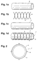
- Fig. la-ld illustrate the structure of the invention Stents 1.
- the stent 1 consists of - as shown in Fig. La is a hose 2 made of an elastic material, one close to the surface of the hose 2 tubular braid 3 - as shown in Fig. 1 b - the is braided from a large number of filaments 5, and one applied to the outer surface of the hose 2 Coating 4 (Fig. 1c).
- 1d shows the stent 1 in assembled condition.
- the inner tube 2 has one smooth inner surface and is due to the composite with the braid 3 consisting of filaments 5, whereby the bond between the tubular braid 3 and the Inner tube 2 is created by means of the coating 4.
- the coating 4 is formed such that by means of the filaments 5 on the outer surface of the Hose 2 distinctive structure through the coating 4 protrudes through to a structured outer surface of the Coating 4 leads.
- Fig. 2 shows a schematic cross section or an end view of the stent according to the invention.
- the stent 1 has a structured outer surface, through the filaments provided with a round cross section 5 is pronounced on the outer surface of the hose 2. This is achieved in that the coating 4 is sufficient is thin, the spaces between the filaments 5 are not complete to be filled in, the one embossed by the filaments 5 Structure of the outer surface of the hose 2 simple is sealed by means of the coating 4.
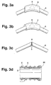
- FIGS. 3a-3d show different ones Ways to hold filament ends 9 together.
- Fig. 3a the ends 9 of the filament 5 by a Cover cap 6 connected to each other protected.
- Fig. 3b the ends 9 of the filaments 5 are each by a common filament tube 7 connected to each other.
- the free ends 9 of the filaments 5 are shown in FIG. 3c a weld 8 assembled and caught.
- Fig. 3d it is alternatively possible to use the free ends of the filaments 5 to capture by an inverting 20 of the inner tube 2.
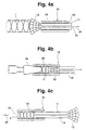
- Fig. 4a and 4b show an application device 10, which is suitable for inserting the stent 1 into a hollow body or to insert into a hollow organ.
- the application device 10 according to FIGS. 4a and 4b consists of an outer application sleeve 15 and an inner catching and sliding device 11.
- the inner catching and sliding device 11 has a spread-out catching device at one end 12 and is on the opposite of the catching device 12 Smooth end.
- the catch and Sliding device 11 provided with a lumen 14.
- Fig. 4a is the stent 1 by means of the spread end of the Catch device 12 in the application sleeve 15 of the application device 10 pulled in the direction of arrow 21.
- the stent 1 is first by means of the spread End 12 of the catching and sliding device 11 in the application sleeve 15 drawn in according to FIG. 4a. After the According to FIG. 4b, stent 1 is completely within the application sleeve 15 is located, the stent 1 by means of the cone plug 16 within the lumen 13 of the application sleeve 15 fixed. A targeted movement of the safety gear 12 in the direction of arrow 21 now releases the stent 1.
- the cone plug 16 is separated from the application sleeve 15 and the catching and sliding device 11 is removed from the application sleeve 15 pulled out, turned over and with her other End pushed back into the application sleeve 15 as shown in FIG. 4c.
- An optical observation of the placement of the Stents 1 are inserted into instruments in a lumen 14 enables.
- the application device 10 is then inside a hollow organ or hollow body, and by moving the catching and sliding device 11 the stent 1 is placed inside the hollow organ.
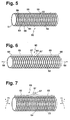
- FIG. 5 shows a stent 50 which consists of a tube 51, a Braid 52 and a coating 53 is formed.
- Next Filament threads 54 from which the braid 52 is made there is a second filament thread next to the threads 54 55, which is interrupted in sections, and its free ends 56 over braid 52 and coating 53 protrude.
- the free ends 56 form barbs for one tissue adjacent to the outer surface of the stent.
- FIG. 6 shows a further embodiment of a stent 60 in the elongated state consisting of a hose 61, a braid 62 and a coating 63 is constructed.
- Anchor 65 On one Surface portion of the outer surface 64 of the stent 60 are Anchor 65 applied.
- the anchors 65 are over a respective one first end 66 stationary with the outer surface 64 of the Stents 60 connected.
- a second end 67 nestles the outer surface 64 of the stent 60.
- the stent 60 is in Direction of arrows 68 elongated.
- the stent 60 of FIG. 6 is in the expanded state shown.
- the stent 60 is expanded in the direction of the arrows 71, so that there is an enlarged lumen 72. While the second ends 67 of the anchors 65 align with the expansion so that they are spaced from the outer surface 64. Via the second ends 67, the armature 65 of the Stents 60 in an adjacent surface or claw.
- a stent 80 which also consists of a Hose 81, a braid 82 and a coating 83 is made.
- the shape of the stent 80 is dependent on its axial and radial extension different.
- the Stent 80 has a bulbous contour 84 that stent 80 in the expanded state.
- the bulbous contour 84 is achieved in that the braid 82 over a form is braided, which has this bulbous contour 84.
- the Contour of a shape can be any and is specific to the application vote.
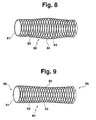
- the bulbous shown in Fig. 8 Contour 64 can also be permanent via thermal deformation can be achieved.
- FIG. 9 shows a further embodiment of a stent 90, who carries a braid 92 on a hose 91, which is of a Coating 93 is covered.
- the Outer contour of the stent 90 over the entire axial extent of the stent 90 has a concave course 94, so that the Stent 90 forms free ends 95, 96, each of which is enlarged Limit lumens in the end region of the stent 90.
- the free ends 95, 96 can still by ring structures on the External surface of the stent 90 are reinforced. These ring structures can also at any section of a Stents regardless of the embodiment of FIG. 9 attached to the outer surface of a stent.
Abstract
Description
Die Erfindung betrifft einen Stent zur Schienung und/oder
zum Offenhalten eines Hohlraums, insbesondere eines Hohlorgans,
wie dieser Stent im Oberbegriff des Anspruchs 1 definiert
wird. Ein solcher Stent ist z.B. aus der Druckschrift WO 95/05132
bekannt.The invention relates to a stent for splinting and / or
to keep a cavity open, in particular a hollow organ,
how this stent is defined in the preamble of
In der DE 1766921 ist eine weitere Stentanordnung zur Schienung bzw. zum Offenhalten eines Hohlorgans beschrieben. Die bekannte Anordnung weist ein aus Filamenten bestehendes tubuläres und selbstexpandierendes Netz auf, das aus einer Vielzahl von ineinander geflochtenen Filamenten besteht. Gemäß einem Ausführungsbeispiel der DE 1766921 ist der Stent als armierter Schlauch ausgebildet, wobei das Netz innerhalb des Schlauchs fest eingebettet ist. Falls der Schlauch aus einem gewebeschonenden Material, beispielsweise aus einem Kunststoff, hergestellt ist, ergibt sich eine Stenteinrichtung die zur Schienung bzw. zum Offenhalten eines Hohlorgans geeignet ist. Da das Netz vollständig innerhalb der Schlauchwandung eingebettet ist, weist die Außenoberfläche des Schlauchs eine glatte Oberfläche auf, die zwar gewebeschonend sein kann, falls der Schlauch aus einem gewebeschonenden Material hergestellt ist, die sich aber möglicherweise gegenüber einer vorgegebenen plazierten Stellung innerhalb des Hohlorgans verschieben kann.DE 1766921 describes a further stent arrangement for splinting or described for keeping a hollow organ open. The well-known The arrangement has a tubular and filament self-expanding network consisting of a variety of interwoven filaments. According to one embodiment DE 1766921 is the stent as an armored one Hose formed, the net inside the hose is firmly embedded. If the hose is made of a tissue-friendly Material, for example made of a plastic, is produced, there is a stent device for Splinting or suitable for keeping a hollow organ open is. Because the net is completely inside the hose wall is embedded, the outer surface of the hose has a smooth surface, which can be gentle on the tissue, if the hose is made of a tissue-friendly material is, but possibly against one given position within the hollow organ can move.
Demgegenüber ist es Aufgabe der vorliegenden Erfindung, einen Stent der obengenannten Art vorzustellen, der kostengünstig herstellbar ist, der eine sichere, gewebeschonende Plazierung innerhalb eines Hohlorgans oder Hohlkörpers ermöglicht und der eine positionsstabile Plazierung dauerhaft ermöglicht.In contrast, it is an object of the present invention, a To introduce a stent of the type mentioned above, which is inexpensive is producible, the safe, tissue-friendly placement within a hollow organ or hollow body and which enables position-stable placement over the long term.
Diese Aufgabe wird gelöst durch einen Stent mit den Merkmalen des Anspruchs 1.This object is achieved by a stent with the features of
Das Ausbilden des erfindungsgemäßen Stents als einen Verbund zwischen drei Komponenten mit einem inneren Schlauch, einem darauf dicht anliegenden angeordneten tubulären Geflecht und einer auf der Außenoberfläche des Schlauchs angeordneten Beschichtung gewährleistet einen Stent, der nicht nur kostengünstig herzustellen ist, sondern der auch eine schonende und sichere Plazierung innerhalb beispielsweise eines Hohlorgans ermöglicht. Die äußere Beschichtung dient dazu, das Geflecht auf der Außenoberfläche des Schlauchs zu fixieren, wobei die Rückstellkräfte (Expansion des Stents aus einem unter Vorspannung stehendem gelängtem Stent kleineren Durchmessers in einen Zustand des Stents mit einem größeren Durchmesser und damit einhergehenden größeren Lumen) durch ein Zusammenwirken der elastischen Eigenschaften des Schlauchs im Verbund mit dem Geflecht bestimmt werden. Die Beschichtung ist derart ausgebildet, daß sich eine strukturierte Oberfläche des Stents ergibt, die durch die Struktur des Geflechts geprägt wird. Auf diese Weise, im Gegensatz zu dem herkömmlichen Stent, weist der erfindungsgemäße Stent eine strukturierte Oberfläche auf, die einen sicheren Halt innerhalb des Hohlorgans gewährleistet. Durch die Auswahl des Materials des Stents, insbesondere des Materials des Geflechts, können die Rückstellkräfte des Stents eingestellt werden. Auf diese Weise wird demzufolge ein kostengünstiger Stent geschaffen, der trotzdem eine sichere Platzierung innerhalb eines Hohlorgans gewährleistet. Die Beschichtung wird ausreichend dünn genug gehalten, damit die Struktur der Filamente zu einer in einzelnen Flächenabschnitten gewölbten Oberfläche des Stent führt. Diese strukturierte Oberfläche dient dazu, daß der Stent innerhalb eines Hohlorgans verbessert gesichert und dauerhaft positionsstabil gehalten werden kann.Forming the stent according to the invention as a composite between three components with an inner tube, one arranged on it closely arranged tubular braid and a coating arranged on the outer surface of the hose ensures a stent that is not only inexpensive to manufacture, but also a gentle one and secure placement within, for example, a hollow organ enables. The outer coating serves to ensure that To fix braid on the outer surface of the hose, the restoring forces (expansion of the stent from a Preloaded elongated stent of smaller diameter into a state of stent with a larger one Diameter and the associated larger lumens) a combination of the elastic properties of the Hose in connection with the braid can be determined. The Coating is designed such that a structured Surface of the stent results from the structure of the braid is shaped. That way, unlike the conventional stent, the stent according to the invention a textured surface that provides a secure grip guaranteed within the hollow organ. By selection the material of the stent, in particular the material of the braid, the restoring forces of the stent can be adjusted become. In this way, it becomes a less expensive one Stent created, which nevertheless has a safe placement within guaranteed a hollow organ. The coating is kept sufficiently thin so that the structure of the Filaments to an arched in individual surface sections Surface of the stent leads. This structured surface serves to improve the stent within a hollow organ secured and permanently held in a stable position can.
Weitere Vorteile ergeben sich, wenn das Geflecht selbstexpandierbar ist. Auf diese Weise sind die Rückstellkräfte des Stents auch durch die Auswahl eines geeigneten Geflechts einstellbar und ergeben sich nicht nur aus den Materialeigenschaften des Schlauchs.There are further advantages if the braid is self-expanding is. In this way, the restoring forces of the stent also by selecting a suitable braid adjustable and result not only from the material properties of the hose.
In einer bevorzugten Ausgestaltung der Erfindung haben die Filamente einen runden Querschnitt. Diese Maßnahme hat den Vorteil, daß herkömmliches Drahtmaterial als geflechtbildende Filamente verwendet werden kann. Zudem ist die einfache Strukturierung durch ein Filament mit einem runden Querschnitt ausreichend, um dem Stent eine geprägte Oberflächenstruktur zu verleihen. In a preferred embodiment of the invention, the Filaments a round cross-section. This measure has the Advantage that conventional wire material as a braid Filaments can be used. In addition, the simple one Structuring through a filament with a round Cross-section sufficient to give the stent an embossed surface structure to rent.
Es ist vorteilhaft, wenn die Filamente Polyester, Kevlar (ein eingetragenes Warenzeichen), Glasfasern, und/oder Metall beinhalten oder aus diesen Materialien gefertigt sind. Polyester hat: den Vorteil, daß es als an sich bekanntes Material mit guten Verarbeitungseigenschaften zur Verfügung steht und dazu geeignet ist, einen stabilen Verbund mit dem Schlauch und der Beschichtung einzugehen. Durch die Auswahl des Materials eines Filaments, beispielsweise Polyester oder Kevlar (ein eingetragenes Warenzeichen), ist es möglich, die Rückstellkräfte des Stents zu beeinflussen. Kevlar (ein eingetragenes Warenzeichen) beispielsweise hat steifere Materialeigenschaften als Polyester und dient dazu, einen Stent zu schaffen, der stärkere Rückstellkräfte aufweist. Die Möglichkeit, die Rückstellkräfte einzustellen, wird durch die Verwendung von Glasfasern erweitert. Metallfilamente haben nicht nur die Eigenschaft, daß sie besonders stark armierte Stentstrukturen gewährleisten, sondern auch, daß die Plazierung und Lage des Stents anhand von Röntgenstrahlenuntersuchungen festgestellt werden kann.It is advantageous if the filaments are polyester, kevlar (a registered trademark), Include glass fibers, and / or metal or from these materials are made. Polyester has: the advantage that it as a known material with good processing properties is available and is suitable for a stable bond with the hose and the coating. By choosing the material of a filament, for example polyester or kevlar (a registered trademark), it is possible to To influence restoring forces of the stent. Kevlar (a registered trademark) for example has stiffer material properties than polyester and serves to create a stent that has greater restoring forces having. The possibility of restoring forces setting is expanded by the use of glass fibers. Metal filaments not only have the property that they ensure particularly strongly reinforced stent structures, but also that the placement and location of the stent can be determined on the basis of X-ray examinations can.
In einer Weiterbildung dieses Ausführungsbeispiels beinhalten die Filamente ein Gemisch aus Glasfasern und Metall. Diese Maßnahme hat den Vorteil, daß die Rückstellkräfte eingestellt werden können, und daß gleichzeitig die Plazierung des Stents durch Röntgenstrahlung kontrolliert werden kann.In a further development of this exemplary embodiment the filaments are a mixture of glass fibers and metal. This measure has the advantage that the restoring forces are set can be, and that at the same time the placement of the stent can be checked by X-rays.
Im allgemeinen ist es vorteilhaft, wenn die Filamente röntgenstrahlendicht ausgebildet sind. Dies hat den Vorteil, daß unabhängig davon, ob die Rückstellkräfte durch beispielsweise Polyester, Kevlar (ein eingetragenes Warenzeichen) oder Metall gegeben sind, es trotzdem möglich ist, die Plazierung des Stents durch Röntgenstrahlen zu kontrollieren. In general, it is advantageous if the filaments are radiopaque are trained. This has the advantage that regardless of whether the restoring forces by, for example Polyester, Kevlar (a registered trademark) or metal are given to it anyway it is possible to place the stent by X-rays to control.
In einer vorteilhaften Weiterbildung dieses Ausführungsbeispiels ist Metallpulver oder sind Metallteile, beispielsweise Wolfram, im Schlauch oder in der Beschichtung enthalten. Diese Maßnahme hat den Vorteil, daß der Stent anhand von Röntgenstrahlenuntersuchungen nicht nur dadurch "sichtbar" wird, die Filamente sind beispielsweise aus einem Metall hergestellt, sondern daß auch anhand der im Stent eingebetteten Metallteile eine verbesserte Röntgenstrahlendichtheit erzielt wird. Auf diese Weise kann durch die Auswahl des Filamentmaterials die Rückstellkraft des Stents in einen expandierten Endzustand beeinflusst werden, und unabhängig davon ist die Plazierung des Stents mittels Röntgenstrahlung kontrolliert möglich.In an advantageous development of this embodiment is metal powder or are metal parts, for example Tungsten, contained in the hose or in the coating. This measure has the advantage that the stent is based on X-ray examinations not only thereby "visible" the filaments are, for example, made of a metal manufactured, but also based on the embedded in the stent Metal parts have improved X-ray tightness is achieved. In this way, by choosing the filament material the restoring force of the stent into an expanded one Final state to be influenced, and regardless is the placement of the stent using X-rays controlled possible.
Es ist besonders vorteilhaft, wenn der Schlauch und/oder die Beschichtung Silikon beinhaltet bzw. beinhalten. Dies hat den Vorteil, daß Silikon ein besonders einfach zu verarbeitendes Material ist, das zusätzlich gute gewebeverträgliche Eigenschaften aufweist.It is particularly advantageous if the hose and / or the Coating contains or contain silicone. this has the advantage that silicone is a particularly easy to process Material is that which is additionally good tissue-compatible Has properties.
Es ist vorteilhaft, wenn die Filamente fest fixierte, geschützte Enden aufweisen. Dies hat den Vorteil, daß die Filamentenden nicht die Beschädigung des Gewebes eines Hohlorgans auslösen können, und daß die strukturelle Stabilität des Stents in den Endbereichen definiert verbessert wird. Das Geflecht kann sich im Endbereich nicht schirmartig nach außen wölben.It is advantageous if the filaments are firmly fixed, protected Have ends. This has the advantage that the filament ends not damage to the tissue of a hollow organ can trigger, and that structural stability of the stent is improved in the end regions. The braid cannot be shield-like in the end area bulge outside.
In einer Weiterbildung dieses Ausführungsbeispiels sind benachbarte Filamentenden paarweise miteinander verbunden. Dies hat den Vorteil, daß die Filamentenden gefangen sind und sich nicht frei ausspreizen können. In a further development of this embodiment, neighboring ones Filament ends connected in pairs. This has the advantage that the filament ends are caught and cannot spread out freely.
In einer bestimmten Form dieser Weiterbildung werden die benachbarten Filamentenden durch eine Überzugskappe miteinander verbunden. Diese Überzugskappe kann schlauch- oder kuvertartig gestaltet werden. Dies hat den Vorteil, daß eine relativ einfache mechanische Konstruktion, nämlich die Überzugskappe, zu einem zuverlässigen Schutz und zur Lokalisierung der Filamentenden führt.In a certain form of this training, the neighboring ones Filament ends with each other through a cover cap connected. This cover cap can be tubular or envelope-like be designed. This has the advantage that a relatively simple mechanical construction, namely the cover cap, for reliable protection and localization of the filament ends.
In einer anderen Form dieser Weiterbildung sind die benachbarten Filamentenden jeweils in einem gemeinsamen Filamentenschlauch gefangen. Der Schlauch schützt die Filamentenden und hält die Enden von mindestens zwei Filamenten zusammen.Another form of this training is the neighboring one Filament ends in a common filament tube captured. The hose protects the filament ends and holds the ends of at least two filaments together.
Es ist aber auch möglich, die Filamentenden zusammenzuschweißen, beispielsweise durch Ultraschallverschweißung. Diese Maßnahme hat den Vorteil, daß kein zusätzliches Material benötigt wird, um eine sichere Lokalisierung und einen sicheren Schutz der Filamentenden zu gewährleisten.But it is also possible to weld the filament ends together, for example by ultrasonic welding. This measure has the advantage that no additional material is needed to ensure safe localization and a to ensure safe protection of the filament ends.
Es ist weiterhin möglich, die Filamentenden fest auf den Silikonschlauch zu kleben und mit einem Silikonüberzug (Film) zu sichern. Die Kreuzungspunkte an den Enden können mittels beispielsweise eines Seidenfadens verknotet bzw. umwickelt werden. Die Kombination des Innenschlauchs und der Überzugskappe bietet den Vorteil, daß sich die Enden beim Strecken des Stents nicht auflösen. Es ist auch möglich, zur besseren Erkennung der Stentenden, wenn der Stent im Körper liegt, die Enden farblich zu markieren. Die Innenoberfläche des Stents kann derart strukturiert sein, daß eine gute und dauerhafte Benetzung von Fluiden und/oder Zellgewebe möglich ist.It is also possible to firmly attach the filament ends to the silicone tube to stick and with a silicone coating (film) to secure. The crossing points at the ends can be done using for example, a silk thread knotted or wrapped become. The combination of the inner tube and the cover cap offers the advantage that the ends are stretched of the stent. It is also possible for better Detection of the stent ends when the stent is in the body mark the ends in color. The inside surface of the Stents can be structured so that they are good and durable Wetting of fluids and / or cell tissue possible is.
Bevorzugt weist der Schlauch eine über die Filamentenden ausgebildete Umstülpung auf. Dies hat den Vorteil, daß der Schlauch und die Filamentenden in Kombination zu gefangenen Filamentenden führen, ohne daß zusätzliche Materialverbindungen hergestellt werden müssen.The hose preferably has one over the filament ends trained inside out. This has the advantage that the Hose and filament ends in combination to catch Lead filament ends without additional material connections have to be manufactured.
In bevorzugter Ausgestaltung weist der Stent über die geprägte strukturierte Außenoberfläche vorstehende Erhebungen auf.In a preferred embodiment, the stent has the embossed one structured outer surface protruding elevations on.
Dies hat den Vorteil, daß der Stent neben der strukturierten Außenoberfläche über Mittel verfügt, die eine gewünschte ortsfeste Endlage eines Stents im Hohlorgan zusätzlich sichern. Die Erhebungen können beliebig auf der Außenumfangsoberfläche des Stents verteilt sein und haben die Wirkung, daß sie sich im angrenzenden Gewebe verteilen, verhaken und/ oder in dieses eindrücken und dadurch die Lage eines Stents zusätzlich sichern.This has the advantage that the stent is next to the structured one Outside surface has means that a desired Secure the fixed end position of a stent in the hollow organ. The elevations can be anywhere on the outer peripheral surface of the stent and have the effect that they spread, get caught and / or or press into it and thereby the location of a stent secure additionally.
Die Erhebungen sind in einer weiteren Ausgestaltung der Erfindung durch freie Enden von Filamentstücken gebildet, die zumindest abschnittsweise neben bzw. parallel zu den das Geflecht bildenden Filamenten verlaufen.The surveys are in a further embodiment of the invention formed by free ends of filament pieces that at least in sections next to or parallel to the braid forming filaments.
Dies hat den Vorteil, daß zur Erstellung derartiger Erhebungen nur ein zweiter Filamentfaden benötigt wird, der beispielsweise parallel zu den das Geflecht bildenden Filamentfäden verlaufen kann. Dieser zweite Filamentfaden, der die Geflechtstruktur bzw. die Geflechtstabilität nicht beeinflussen muß, wird nach gewünschten Abschnittslängen durchgetrennt und die dadurch entstehenden freien Enden werden über die Außenoberfläche des Stents vorstehend nach außen gebogen, so daß eine Außenoberfläche mit zahlreichen Haken entsteht, die sich in einem angrenzenden Gewebe verkrallen können. This has the advantage that to create such surveys only a second filament thread is needed, for example parallel to the filament threads forming the braid can run. This second filament thread that the Do not influence the braid structure or the braid stability must be cut according to the desired section lengths and the resulting free ends are over the outer surface of the stent protrudes outward, so that there is an outer surface with numerous hooks, that can cling to an adjacent tissue.
Bei einer weiteren Ausgestaltung des erfindungsgemäßen Stents sind die Erhebungen durch Anker gebildet, die im gelängten Zustand des Stents auf der Außenoberfläche des Stents flach anliegen und mit einem ersten Ende an der Außenoberfläche des Stents ortsfest befestigt sind und mit einem freien zweiten Ende im expandierten Zustand des Stents von der Außenoberfläche des Stents beabstandet sind.In a further embodiment of the invention The elevations are formed by anchors that are elongated in the stents Condition of the stent on the outer surface of the Stents lie flat and with a first end on the outer surface of the stent are fixed and with a free second end in the expanded state of the stent are spaced from the outer surface of the stent.
Dies hat den Vorteil, daß derartige Anker auch nachträglich auf einer strukturierten Außenoberfläche eines Stents angebracht werden können. Die Anker entfalten sich erst bei der Expansion des Stents und dringen dabei in das angrenzende Gewebe ein. Im gelängten Zustand eines Stents liegen diese Anker flach auf der Außenoberfläche eines Stents an, so daß die Plazierung eines Stents durch diese Anker nicht erschwert wird.This has the advantage that such anchors can also be retrofitted attached to a structured outer surface of a stent can be. The anchors only unfold at the Expansion of the stent and penetrate into the adjacent one Tissue. These lie in the elongated state of a stent Anchor flat on the outer surface of a stent so that the placement of a stent by these anchors is not difficult becomes.
In einer weiteren Ausführungsform eines erfindungsgemäßen Stents sind die das Geflecht bildenden Filamente unterschiedlich weit voneinander beabstandet und/oder die Filamente weisen einen unterschiedlichen Durchmesser auf.In a further embodiment of an inventive In stents, the filaments that form the braid are different spaced far apart and / or the filaments have a different diameter.
Über die Variation von Geflechtsarten und/oder Maschenweiten sowie über die Dicken der einzelnen Filamentfäden lassen sich vorbestimmbare Rückstellkräfte in einem Stent verwirklichen, so daß je nach Größe und Beschaffenheit einer Hohlorganengstelle immer der dafür bestmöglich geeignete Stent ausgewählt werden kann, damit dieser Stent eine gewünschte Lumenerweiterung im entsprechenden Hohlorgan dauerhaft sichert und eine unbeabsichtigte Migration des Stents ausgeschlossen werden kann. About the variation of braid types and / or mesh sizes as well as the thickness of the individual filament threads predetermined restoring forces are realized in a stent, so that depending on the size and nature of a hollow organ constriction always the best possible stent for this can be selected so that this stent is a desired one Lumen expansion in the corresponding hollow organ permanently secures and preclude inadvertent migration of the stent can be.
Ist das Geflecht eines Stents bei einer weiteren Ausführungsform über einer in axialer und/oder radialer Richtung unterschiedliche Kontur aufweisenden Form hergestellt, so kann noch zusätzlich in Abhängigkeit vom axialen Verlauf eines Stents die Rückstellkraft innerhalb eines Stents variiert werden. Unterschiedliche Formen eines Geflechts lassen sich auch über eine thermische Verformung herstellen.The braid of a stent is in another embodiment over one in the axial and / or radial direction manufactured different contour shape, so can additionally depending on the axial course of a Stents the restoring force varies within a stent become. Let different forms of a braid also produce themselves via thermal deformation.
Es ist besonders vorteilhaft, wenn der Stent derart ausgebildet ist, daß er mittels einer Applikationseinrichtung in einen Hohlkörper einbringbar ist. Dies hat den Vorteil, daß die Plazierung des Stents erleichtert wird und reproduzierbare Methoden zur Plazierung des erfindungsgemäßen Stents erarbeitet werden können.It is particularly advantageous if the stent is designed in this way is that he uses an application device in a hollow body can be introduced. This has the advantage that placement of the stent is facilitated and reproducible Methods for placing the stent according to the invention can be worked out.
In einer Weiterbildung dieses Ausführungsbeispiels weist die Applikationseinrichtung eine Fang- und Schiebeeinrichtung, eine Applikationshülse und einen Kegel-Pfropfen auf. Dies hat den Vorteil, daß der Stent mit dieser Applikationseinrichtung nicht nur in ein Hohlorgan eingebracht, sondern auch mit dieser Einrichtung plaziert werden kann. Der Kegel-Pfropfen dient zur leichteren Handhabung in der Applikationshülse.In a development of this embodiment, the Application device a catching and sliding device, an application sleeve and a cone plug. This has the advantage that the stent with this application device not only introduced into a hollow organ, but can also be placed with this device. The cone plug serves for easier handling in the application sleeve.
In einer Weiterbildung dieser Ausführungsform weist die Fang- und Schiebeeinrichtung einen aufgespreizten Fängerkorb aus einem Kunststoff- oder Metallgeflecht auf. Dies hat den Vorteil, daß die Fang- und Schiebeeinrichtung in der Lage ist, den Stent sicher zu fangen, und, nachdem der Stent innerhalb der Applikationshülse zusammengelegt gehalten ist, wieder freizugeben. Die Fang- und Schiebeeinrichtung ist derart ausgebildet und dimensioniert, daß sie in das Lumen der Applikationshülse einschiebbar ist.In a development of this embodiment, the Catch and slide device a spread catch basket from a plastic or metal braid. This has the Advantage that the catching and sliding device is able is to safely catch the stent, and after the stent is inside the application sleeve is kept folded, to release again. The catching and sliding device is designed and dimensioned such that they enter the lumen the application sleeve can be inserted.
Der Fängerkorb weist gegenüber der Applikationshülse und/ oder dem Stent eine erhöhte Gleitfähigkeit auf, wenn in das Geflecht des Fängerkorbs eine Silikonmasse eingearbeitet ist (reibungsmindernd sind beispielsweise auch Beschichtungen aus Teflon (ein eingetragenes Warenzeichen) oder polyäthylen). Dies gewährleistet ein sicheres und leichteres Entfernen der Fang- und Schiebeeinrichtung vom darin eingefangenen Stent.The catcher basket faces the application sleeve and / or the stent has increased lubricity when in that Mesh of the catcher basket is incorporated a silicone compound (Coating also reduces friction, for example made of Teflon (a registered trademark) or polyethylene). This ensures a safe one and easier removal of the catching and sliding device from the stent captured in it.
Vorteilhaft ist es, wenn die Fang- und Schiebeeinrichtung ein Lumen aufweist. Dies hat den Vorteil, daß das Lumen der Fang- und Schiebeeinrichtung dazu geeignet ist, über optische Mittel eine Beobachtung der Plazierung des Stents innerhalb eines Hohlorgans zu gewährleisten.It is advantageous if the catching and sliding device has a lumen. This has the advantage that the lumen of the Catch and slide device is suitable via optical Medium observation of stent placement within to ensure a hollow organ.
In einer vorteilhaften Weiterbildung ist die Fang- und Schiebeeinrichtung eine Unterstützung für den Stent, wenn ein Bereich des freien Endes der Schiebevorrichtung in das Stentlumen hineinragt. Kleine Stentgrößen < 10 mm Innendurchmesser, können beim Herausschieben aus der Applikationshülse nicht beschädigt werden, weil sie aus dem Innenbereich heraus gestützt werden. Ein zusätzlicher Einsatz von Gleitmittel im Außenbereich des Stents ist möglich, damit die Reibung zwischen der Innenoberfläche der Applikationshülse und der Außenoberfläche des Stents herabgesetzt wird.In an advantageous development, the catch and Slider support for the stent if an area of the free end of the pusher into that Stent lumen protrudes. Small stent sizes <10 mm inner diameter, can when sliding out of the application sleeve not be damaged because they are from the interior be supported out. An additional use of Lubricant in the outer area of the stent is therefore possible the friction between the inner surface of the application sleeve and the outer surface of the stent is degraded.
Um den Stent aus dem Fängerkorb zu entfernen, ist es notwendig, diesen nicht ganz in die Applikationshülse zu ziehen. Mit einem Kegel-Pfropfen wird der Stent in der Applikationshülse fixiert und der Fängerkorb herausgezogen. Das überstehende Geflecht kann dann in die Applikationshülse, z.B. unter Zuhilfenahme der Kegelpfropfen-Rückseite schonend eingeführt werden. Wird der Kegel-Pfropfen nicht benützt, kann dies zu Deformationen und Beschädigungen am Stent, besonders bei den Größen kleiner als 10 mm Innendurchmesser führen.In order to remove the stent from the catcher basket, it is necessary not pull it fully into the application sleeve. The stent is placed in the application sleeve with a cone plug fixed and the catcher basket pulled out. The supernatant Braid can then be inserted into the application sleeve, e.g. under With the aid of the back of the cone plug gently inserted become. If the cone plug is not used, can this leads to deformations and damage to the stent, especially for sizes smaller than 10 mm inner diameter.
Die Kombination von Fangeinrichtung und Applikationshülse kann so gestaltet werden, daß beide Gegenstände mit geringen Wandstärken hergestellt werden können. Die Applikationshülse weist dabei eine Wandstärke auf, die so dünn ist, daß sie durch die Fangeinrichtung stabilisiert werden muß.The combination of safety gear and application sleeve can be designed so that both objects with low Wall thicknesses can be produced. The application sleeve has a wall thickness that is so thin that it must be stabilized by the safety gear.
Durch die Materialauswahl ist es möglich, ein hohes Maß an Flexibilität zu erreichen. Dies hat den Vorteil, daß eine sichere, einfache und körperschonende Implantation des Stents gewährleistet wird.Through the choice of materials it is possible to have a high level of Achieve flexibility. This has the advantage that a safe, simple and body-friendly implantation of the Stents is guaranteed.
Ein Verfahren zum Einbringen des Stents kann vorsehen, daß der Stent mittels des sich konisch ausspreizenden Endes der Fang- und Schiebeeinrichtung in das Lumen der Applikationshülse eingezogen wird, der Stent mittels des Kegel-Pfropfens innerhalb des Lumens der Applikationshülse fixiert wird, die Fang- und Schiebeeinrichtung von dem Stent getrennt und aus dem Lumen der Applikationshülse herausgezogen wird, der Kegel-Pfropfen von der Applikationshülse getrennt wird, die Fang- und Schiebeeinrichtung umgedreht und wieder in das Lumen der Applikationshülse eingeschoben wird, optische Mittel durch das Lumen der Fang- und Schiebeeinrichtung einschiebbar sind, die Applikationshülse in den Hohlkörper eingebracht wird, und der Stent mittels der Fang- und Schiebeeinrichtung aus der Applikationshülse heraus in den Hohlkörper plaziert wird. Dies hat den Vorteil, daß der Stent auf eine einfache und sichere Art und Weise mittels der Applikationseinrichtung zunächst in der Applikationshülse gefangen und kollabiert gehalten werden kann. Die Fang- und Schiebeeinrichtung wird nicht nur dazu benutzt, um den Stent in die Applikationshülse einzuziehen, sondern auch um den Stent aus der Applikationshülse in das Hohlorgan herauszuschieben. Die Fang- und Schiebeeinrichtung weist demzufolge ein Ende mit einer Fangeinrichtung und ein der Fangeinrichtung gegenüberliegendes Ende auf, das zum Schieben des Stents aus der Applikationshülse heraus in das Hohlorgan ausgebildet ist.A procedure for inserting the stent can provide that the stent by means of the conically spreading End of the catching and sliding device in the Lumen of the application sleeve is drawn in using the stent of the cone plug within the lumen of the application sleeve is fixed, the catching and sliding device from separated from the stent and from the lumen of the application sleeve is pulled out, the cone plug from the application sleeve is separated, the catching and pushing device is turned over and pushed back into the lumen of the application sleeve will, optical means through the lumen of the capture and Sliding device can be inserted, the application sleeve is introduced into the hollow body, and by means of the stent the catch and slide device from the application sleeve is placed out in the hollow body. This has the advantage that the stent in a simple and safe way and Way by means of the application device first in the Application sleeve can be caught and collapsed can. The catching and sliding device is not only used for this used to pull the stent into the application sleeve, but also around the stent from the application sleeve into the To push out the hollow organ. The catching and sliding device accordingly has an end with a safety gear and a the catching device opposite end to the Push the stent out of the application sleeve into the Hollow organ is formed.
Ein Verfahren zur Herstellung eines Stents kann folgende Schritte vorsehen: das Geflecht wird auf die Außenoberfläche des Schlauchs dicht anliegend aufgebracht, und danach werden der Schlauch und das Geflecht in eine Flüssigkeit, beispielsweise Silikon, getaucht. Diese Flüssigkeit verfestigt sich und bildet die zweite Beschichtung.A method of making a Stents can provide the following steps: the braid becomes close to the outer surface of the hose applied, and then the hose and braid immersed in a liquid, for example silicone. This Liquid solidifies and forms the second coating.
Die freien Enden des Geflechts können auch jeweils miteinander verschweißt werden und zusätzlich durch eine Klebeschicht geschützt werden. Enthält die Klebeschicht Bariumsulfat, so sind die Stentenden röntgenschattengebend.The free ends of the braid can also be connected to each other be welded and additionally by an adhesive layer to be protected. Does the adhesive layer contain barium sulfate, so the stent ends are radiopaque.
Dies hat den Vorteil, daß der erfindungsgemäße Stent einfachst hergestellt werden kann.This has the advantage that the stent according to the invention is simplest can be manufactured.
Weitere Vorteile der Erfindung ergeben sich aus der Beschreibung und der Zeichnung. Further advantages of the invention result from the description and the drawing.
Es zeigt:
- Fig. 1a
- einen dem Stent zugrunde liegenden Schlauch;
- Fig. 1b
- ein dem Stent zugrunde liegendes Geflecht;
- Fig. 1c
- eine dem erfindungsgemäßen Stent zugrunde liegende Beschichtung;
- Fig. 1d
- eine schematische Darstellung des den erfindungsgemäßen Stent bildenden Verbunds zwischen Schlauch, Geflecht und Beschichtung;
- Fig. 2
- einen schematischen Querschnitt bzw. eine Endansicht des erfindungsgemäßen Stents gemäß Fig. ld;
- Fig. 3a
- ein erfindungsgemäßes Ausführungsbeispiel von gefangenen freien Filamentenden mittels einer Überzugskappe;
- Fig. 3b
- ein weiteres erfindungsgemäßes Ausführungsbeispiel von gefangenen Filamentenden mittels eines Filamentenschlauchs;
- Fig. 3c
- ein Ausführungsbeispiel mit verschweißten Filamentenden;
- Fig. 3d
- eine Umstülpung des Schlauchs, das den Zusammenhalt der Filamentenden bewirkt;
- Fig. 4a
- eine erfindungsgemäße Applikationseinrichtung zur Plazierung des erfindungsgemäßen Stents;
- Fig. 4b
- eine Applikationseinrichtung gemäß Fig. 4a mit eingezogenem Stent und Kegel-Pfropfen;
- Fig. 4c
- eine Applikationseinrichtung mit einer gegenüber Fig. 4a gedrehten Fang- und Schiebeeinrichtung;
- Fig. 5
- einen Stent mit Erhebungen auf der Außenumfangsfläche, die durch freie Enden von Filamentstücken gebildet sind;
- Fig. 6
- einen Stent mit auf der Außenoberfläche angebrachten Ankern im gelängten Zustand;
- Fig. 7
- einen Stent gemäß Fig. 6 im expandierten Zustand;
- Fig. 8
- einen Stent mit in Abhängigkeit vom axialen und radialen Verlauf unterschiedlicher Oberflächenkontur;
- Fig. 9
- einen Stent im expandierten Zustand mit jeweils erweitertem Lumen im freien Endbereich.
- Fig. 1a
- a tube underlying the stent;
- Fig. 1b
- a braid underlying the stent;
- Fig. 1c
- a coating on which the stent according to the invention is based;
- Fig. 1d
- a schematic representation of the composite forming the stent according to the invention between tube, braid and coating;
- Fig. 2
- a schematic cross section or an end view of the stent according to the invention according to FIG.
- Fig. 3a
- an inventive embodiment of trapped free filament ends by means of a cover cap;
- Fig. 3b
- a further embodiment of trapped filament ends according to the invention by means of a filament tube;
- 3c
- an embodiment with welded filament ends;
- Fig. 3d
- an inside-out of the tube, which holds the filament ends together;
- Fig. 4a
- an application device according to the invention for placing the stent according to the invention;
- Fig. 4b
- an application device according to FIG 4a with retracted stent and cone plug.
- Fig. 4c
- an application device with a catch and slide device rotated relative to FIG. 4a;
- Fig. 5
- a stent with bumps on the outer peripheral surface formed by free ends of filament pieces;
- Fig. 6
- a stent with anchors attached to the outer surface in the elongated state;
- Fig. 7
- 6 in the expanded state;
- Fig. 8
- a stent with different surface contours depending on the axial and radial course;
- Fig. 9
- a stent in the expanded state, each with an enlarged lumen in the free end area.
Die Figuren sind teilweise sehr schematisch dargestellt, um die wesentlichen erfinderischen Merkmale zu verdeutlichen. In den Darstellungen sind die Dimensionen nur beispielhaft und nicht maßstäblich zu verstehen.Some of the figures are shown very schematically to clarify the essential inventive features. The dimensions in the illustrations are only examples and not to scale to understand.
Fign. la-ld veranschaulichen den Aufbau des erfindungsgemäßen
Stents 1. Der Stent 1 besteht aus - wie in Fig. la dargestellt
ist - einem Schlauch 2 aus einem elastischen Material,
einem an der Oberfläche des Schlauchs 2 dicht anliegenden
tubulären Geflecht 3 - wie in Fig. 1 b gezeigt - das
aus einer Vielzahl von Filamenten 5 zusammengeflochten ist,
sowie einer auf der Außenoberfläche des Schlauchs 2 aufgetragenen
Beschichtung 4 (Fig. 1c). Fig. ld zeigt den Stent 1
in zusammengebautem Zustand. Der innere Schlauch 2 weist eine
glatte innere Oberfläche auf und ist durch den Verbund
mit dem aus Filamenten 5 bestehenden Geflecht 3 armiert, wobei
der Verbund zwischen dem tubulären Geflecht 3 und dem
Innenschlauch 2 mittels der Beschichtung 4 geschaffen wird.
Gemäß Fig. 1d ist die Beschichtung 4 derart ausgebildet, daß
die mittels der Filamente 5 auf der Außenoberfläche des
Schlauchs 2 ausgeprägte Struktur durch die Beschichtung 4
hindurchragt und zu einer strukturierten Außenoberfläche der
Beschichtung 4 führt.Fig. la-ld illustrate the structure of the
Fig. 2 zeigt einen schematischen Querschnitt bzw. eine Endansicht
des erfindungsgemäßen Stents. Der innere Schlauch 2
sowie das aus Filamenten 5 bestehende Geflecht 3, das auf
der Außenoberfläche des inneren Schlauchs 2 dicht anliegt,
sind mittels der relativ dünnen Beschichtung 4 haftend zusammengehalten.
In dem Ausführungsbeispiel gemäß Fig. 2
weist der Stent 1 eine strukturierte Außenoberfläche auf,
die durch die mit rundem Querschnitt versehenen Filamente 5
auf der Außenoberfläche des Schlauchs 2 ausgeprägt ist. Dies
wird dadurch erreicht, daß die Beschichtung 4 ausreichend
dünn ist, um die Räume zwischen den Filamenten 5 nicht vollständig
auszufüllen, wobei die durch die Filamente 5 geprägte
Struktur der Außenoberfläche des Schlauchs 2 einfach
mittels der Beschichtung 4 dichtend überzogen ist.Fig. 2 shows a schematic cross section or an end view
of the stent according to the invention. The
Die Ausführungsbeispiele gemäß Fign. 3a-3d zeigen verschiedene
Möglichkeiten, um Filamentenden 9 fest zusammenzuhalten.
In Fig. 3a werden die Enden 9 des Filaments 5 durch eine
Überzugskappe 6 miteinander geschützt verbunden. Gemäß
Fig. 3b werden die Enden 9 der Filamente 5 jeweils durch einen
gemeinsamen Filamentenschlauch 7 miteinander verbunden.
Die freien Enden 9 der Filamente 5 sind gemäß Fig. 3c durch
eine Verschweißung 8 zusammengefügt und gefangen. Gemäß Fig.
3d ist es alternativ möglich, die freien Enden der Filamente
5 durch eine Umstülpung 20 des inneren Schlauchs 2 einzufangen.The exemplary embodiments according to FIGS. 3a-3d show different ones
Ways to hold filament ends 9 together.
In Fig. 3a, the
Fign. 4a und Fig. 4b zeigen eine Applikationseinrichtung 10,
die dazu geeignet ist, den Stent 1 in einen Hohlkörper bzw.
in ein Hohlorgan einzuführen. Die Applikationseinrichtung 10
gemäß Fign. 4a und 4b besteht aus einer äußeren Applikationshülse
15 sowie einer inneren Fang- und Schiebeeinrichtung
11. Die innere Fang- und Schiebeeinrichtung 11
weist an ihrem einen Ende eine ausgespreizte Fangeinrichtung
12 auf und ist auf dem der Fangeinrichtung 12 gegenüberliegenden
Ende glatt ausgebildet. Zudem ist die Fang- und
Schiebeeinrichtung 11 mit einem Lumen 14 versehen. In Fig.
4a wird der Stent 1 mittels des ausgespreizten Endes der
Fangeinrichtung 12 in die Applikationshülse 15 der Applikationseinrichtung
10 in Richtung des Pfeils 21 hineingezogen.
Dazu ist der Außendurchmesser der Fang- und Schiebeeinrichtung
11 derart dimensioniert, daß sie innerhalb eines Lumens
13 der Applikationshülse 15 schiebbar angeordnet werden
kann. Gemäß Fig. 4c wird ein bereits eingefangener Stent 1
mittels der Fang- und Schiebeeinrichtung 11 in Richtung
Pfeil 22 aus der Applikationshülse 15 hinausgeschoben und
innerhalb eines Hohlorgans plaziert.Fig. 4a and 4b show an
Um die Applikationseinrichtung gemäß Fign. 4a, 4b und 4c zu
benutzen, wird zunächst der Stent 1 mittels des ausgespreizten
Endes 12 der Fang- und Schiebeeinrichtung 11 in die Applikationshülse
15 gemäß Fig. 4a hineingezogen. Nachdem der
Stent 1 sich gemäß Fig. 4b vollständig innerhalb der Applikationshülse
15 befindet, wird der Stent 1 mittels des Kegel-Pfropfens
16 innerhalb des Lumens 13 der Applikationshülse
15 fixiert. Eine gezielte Bewegung der Fangeinrichtung
12 in Pfeilrichtung 21 gibt nun den Stent 1 frei. Der Kegel-Pfropfen
16 wird von der Applikationshülse 15 getrennt und
die Fang- und Schiebeeinrichtung 11 wird aus der Applikationshülse
15 herausgezogen, umgedreht und mit ihrem anderen
Ende wieder in die Applikationshülse 15 gemäß Fig. 4c hineingeschoben.
Eine optische Beobachtung des Plazierens des
Stents 1 wird durch in ein Lumen 14 einführbare Instrumente
ermöglicht. Die Applikationseinrichtung 10 wird danach innerhalb
eines Hohlorgans oder Hohlkörpers plaziert, und
durch eine Verschiebung der Fang- und Schiebeeinrichtung 11
wird der Stent 1 innerhalb des Hohlorgans plaziert.In order to apply the application device according to FIGS. 4a, 4b and 4c
use, the
Fig. 5 zeigt einen Stent 50, der aus einem Schlauch 51, einem
Geflecht 52 und einer Beschichtung 53 gebildet ist. Neben
Filamentfäden 54, aus denen das Geflecht 52 hergestellt
ist, verläuft neben den Fäden 54 ein zweiter Filamentfaden
55, der abschnittsweise unterbrochen ist, und dessen
freie Enden 56 über das Geflecht 52 und die Beschichtung 53
vorstehen. Die freien Enden 56 bilden Widerhaken für ein an
die Stentaußenoberfläche angrenzendes Gewebe. 5 shows a
Fig. 6 zeigt eine weitere Ausführungsform eines Stents 60 im
gelängten Zustand, der aus einem Schlauch 61, einem Geflecht
62 und einer Beschichtung 63 aufgebaut ist. An einem
Flächenabschnitt der Außenoberfläche 64 des Stents 60 sind
Anker 65 aufgebracht. Die Anker 65 sind über ein jeweiliges
erstes Ende 66 ortsfest mit der Außenoberfläche 64 des
Stents 60 verbunden. Ein zweites Ende 67 schmiegt sich an
die Außenoberfläche 64 des Stents 60 an. Der Stent 60 ist in
Pfeilrichtungen 68 gelängt.6 shows a further embodiment of a
In Fig. 7 ist der Stent 60 der Fig. 6 im expandierten Zustand
gezeigt. Der Stent 60 ist in Pfeilrichtungen 71 expandiert,
so daß sich ein vergrößertes Lumen 72 ergibt. Während
der Expansion richten sich die zweiten Enden 67 der Anker 65
auf, so daß sie von der Außenoberfläche 64 beabstandet sind.
Über die zweiten Enden 67 können sich die Anker 65 des
Stents 60 in einer angrenzenden Oberfläche verhaken bzw.
verkrallen.7, the
Fig. 8 zeigt einen Stent 80, der ebenfalls aus einem
Schlauch 81, einem Geflecht 82 und einer Beschichtung 83 besteht.
Die Form des Stents 80 ist in Abhängigkeit von seiner
axialen und radialen Erstreckung unterschiedlich. Der
Stent 80 weist eine bauchige Kontur 84 auf, die der Stent 80
im expandierten Zustand einnimmt. Die bauchige Kontur 84
wird dadurch erreicht, daß das Geflecht 82 über einer Form
geflochten wird, die diese bauchige Kontur 84 aufweist. Die
Kontur einer Form kann beliebig sein und ist auf den Anwendungsfall
abzustimmen. Die in der Fig. 8 gezeigte bauchige
Kontur 64 kann dauerhaft auch über eine thermische Verformung
erreicht werden.8 shows a
Fig. 9 zeigt eine weitere Ausführungsform eines Stents 90,
der auf einem Schlauch 91 ein Geflecht 92 trägt, das von einer
Beschichtung 93 überdeckt ist. Im Querschnitt weist die
Außenkontur des Stents 90 über die gesamte axiale Erstrekkung
des Stents 90 einen konkaven Verlauf 94 auf, so daß der
Stent 90 freie Enden 95, 96 bildet, die jeweils ein vergrößertes
Lumen im Endbereich des Stents 90 begrenzen. Die
freien Enden 95, 96 können noch durch Ringstrukturen auf der
Außenoberfläche des Stents 90 verstärkt werden. Diese Ringstrukturen
können auch an beliebigen Abschnitten eines
Stents unabhängig von dem Ausführungsbeispiel der Fig. 9 an
der Außenoberfläche eines Stents angebracht werden.9 shows a further embodiment of a
Claims (24)
- Stent for the splinting and/or holding-open of a body cavity havinga first layer (2) made from an elastic material;a tubular weave (3) seating firmly on the outer surface of the first layer (2) and made from filaments (5) anda second layer (4) applied to both the weave (3) as well as the outer surface of the first layer (2) which holds the weave (3) on the outer surface of the first layer (2), wherein the diameter of the filaments (5) forming the weave (3) is larger than the thickness of the second layer (4), characterized in that the first layer is a tube (2), having a smooth inner surface, and on which the tubular weave (3) seats, and the second layer is fashioned on the tube (2) as self-solidifying through layer (4), self-solidification following dipping into a fluid to form a structured outer surface defined by the weave (3).
- Stent according to claim 1, characterized in that the weave (3) is self-expanding.
- Stent according to anyone of the preceding claims, characterized in that the filaments (5) have a rounded cross section.
- Stent according to any one of the preceding claims, characterized in that the filaments (5) contain or are made from polyester, kevlar, fiber glass and/or metal.
- Stent according to any one of the preceding claims, characterized in that the filaments (5) are impervious to X-rays.
- Stent according to any one of the claims 1 through 5, characterized in that a metallic powder or metallic pieces are contained in the tube (2) or in the coating (4), e.g. tungsten.
- Stent according to any one of the preceding claims, characterized in that the tube (2) and/or the coating (4) contain silicon or are made from same.
- Stent according to any one of the preceding claims, characterized in that the filaments (5) have fixed ends (9) which are, in particular, protected.
- Stent according to claim 8, characterized in that neighbouring filament ends (9) are pairwise connected to each other.
- Stent according to claim 9, characterized in that the neighbouring filament ends (9) are connected to each other by means of a covering cap (6).
- Stent according to claim 9, characterized in that the neighbouring filament ends (9) are captured in a common filament tube (7).
- Stent according to claim 9, characterized in that the neighbouring filament ends (9) are welded (8) together, e.g. by means of ultrasound weldment.
- Stent according to any one of the claims 1 through 12, characterized in that the tube (2) has a fold-over (20) covering the ends of the filaments.
- Stent according to any one of the claims 1 through 13, characterized in that the stent (50;60;80) has raised portions (56;65;84;95,96) protruding beyond the embossed structured outer surface.
- Stent according to claim 14, characterized in that the raised portions are formed by the free ends (56) of filament pieces which extend at least in sections proximate or parallel to the filament threads (54) forming the weave (52).
- Stent according to claim 14 or 15, characterized in that the raised portions are formed by anchors (65) which seat flatly on the outer surface (64) of the stent (60) in the elongated state of the stent (60) and are firmly attached in a fixed spatial location at a first end (66) thereof to the outer surface (64) of the stent (60) and which are separated from the outer surface (64) of the stent (60) at a second free end (67) thereof in an expanded state of the stent (60).
- Stent according to any one of the claims 1 through 16, characterized in that the filament threads forming the weave (52;62;82;92) have differing separations with respect to each other and/or have a differing diameter.
- Stent according to any one of the claims 1 through 17, characterized in that the weave (82;92) can be produced on a mould having differing shapes in the axial and/or radial directions.
- Stent according to any one of the claims 1 through 17, characterized in that the shape of the weave (82;92) is produced by means of thermal shaping techniques.
- Stent according to any one of the preceding claims, characterized in that the stent (1) is configured in such a fashion that it can be introduced into a body cavity using an application device (10).
- Stent according to claim 20, characterized in that the application device (10) has a capture and displacement device (11), an application bushing (15) and a conical plug (16).
- Stent according to claim 21, characterized in that the capture and displacement device (11) has a substantially conically spread-out end (12).
- Stent according to claim 21 or 22, characterized in that the capture and displacement device (11) is shaped and dimensioned in such a fashion that it can be displaced into the lumen (13) of the application bushing (15).
- Stent according to any one of the claims 21 through 23, characterized in that the capture and displacement device (11) has a lumen (14).
Applications Claiming Priority (5)
| Application Number | Priority Date | Filing Date | Title |
|---|---|---|---|
| DE19612615 | 1996-03-29 | ||
| DE19612615 | 1996-03-29 | ||
| DE19707642A DE19707642A1 (en) | 1996-03-29 | 1997-02-26 | Stent |
| DE19707642 | 1997-02-26 | ||
| PCT/DE1997/000649 WO1997036556A1 (en) | 1996-03-29 | 1997-03-27 | Stent |
Publications (2)
| Publication Number | Publication Date |
|---|---|
| EP0901353A1 EP0901353A1 (en) | 1999-03-17 |
| EP0901353B1 true EP0901353B1 (en) | 2001-07-11 |
Family
ID=26024284
Family Applications (1)
| Application Number | Title | Priority Date | Filing Date |
|---|---|---|---|
| EP97920561A Expired - Lifetime EP0901353B1 (en) | 1996-03-29 | 1997-03-27 | Stent |
Country Status (6)
| Country | Link |
|---|---|
| US (1) | US6162244A (en) |
| EP (1) | EP0901353B1 (en) |
| JP (1) | JP3645911B2 (en) |
| AT (1) | ATE202915T1 (en) |
| ES (1) | ES2159862T3 (en) |
| WO (1) | WO1997036556A1 (en) |
Cited By (2)
| Publication number | Priority date | Publication date | Assignee | Title |
|---|---|---|---|---|
| DE10219014A1 (en) * | 2002-04-27 | 2003-11-13 | Ruesch Willy Gmbh | Self-expanding stent for reinforcing and/or keeping open a hollow organ comprise two elastic tubular layers which bracket and positionally fix at least one helical filament |
| US7731742B2 (en) | 2002-05-11 | 2010-06-08 | Boston Scientific Scimed, Inc. | Stent |
Families Citing this family (57)
| Publication number | Priority date | Publication date | Assignee | Title |
|---|---|---|---|---|
| DE19703482A1 (en) | 1997-01-31 | 1998-08-06 | Ernst Peter Prof Dr M Strecker | Stent |
| DE69732229T2 (en) * | 1997-07-17 | 2005-12-29 | Schneider (Europe) Gmbh | Stent and manufacturing process for it |
| US6273917B1 (en) * | 1998-03-27 | 2001-08-14 | Kanji Inoue | Transplantation device |
| US7018401B1 (en) | 1999-02-01 | 2006-03-28 | Board Of Regents, The University Of Texas System | Woven intravascular devices and methods for making the same and apparatus for delivery of the same |
| US6299448B1 (en) * | 1999-02-17 | 2001-10-09 | Ivanka J. Zdrahala | Surgical implant system for restoration and repair of body function |
| US6858034B1 (en) * | 1999-05-20 | 2005-02-22 | Scimed Life Systems, Inc. | Stent delivery system for prevention of kinking, and method of loading and using same |
| US10172730B2 (en) * | 1999-11-19 | 2019-01-08 | Vactronix Scientific, Llc | Stents with metallic covers and methods of making same |
| US6355063B1 (en) * | 2000-01-20 | 2002-03-12 | Impra, Inc. | Expanded PTFE drug delivery graft |
| US7118592B1 (en) | 2000-09-12 | 2006-10-10 | Advanced Cardiovascular Systems, Inc. | Covered stent assembly for reduced-shortening during stent expansion |
| US6716444B1 (en) | 2000-09-28 | 2004-04-06 | Advanced Cardiovascular Systems, Inc. | Barriers for polymer-coated implantable medical devices and methods for making the same |
| US6953560B1 (en) | 2000-09-28 | 2005-10-11 | Advanced Cardiovascular Systems, Inc. | Barriers for polymer-coated implantable medical devices and methods for making the same |
| DE10064596A1 (en) | 2000-12-18 | 2002-06-20 | Biotronik Mess & Therapieg | Application of a marker element to an implant, especially a stent, comprises introducing a solidifiable material into a recess and solidifying the material in the recess |
| US6663662B2 (en) | 2000-12-28 | 2003-12-16 | Advanced Cardiovascular Systems, Inc. | Diffusion barrier layer for implantable devices |
| US6641607B1 (en) | 2000-12-29 | 2003-11-04 | Advanced Cardiovascular Systems, Inc. | Double tube stent |
| US20030153971A1 (en) * | 2002-02-14 | 2003-08-14 | Chandru Chandrasekaran | Metal reinforced biodegradable intraluminal stents |
| US7780687B2 (en) * | 2002-04-17 | 2010-08-24 | Tyco Healthcare Group Lp | Method and apparatus for anastomosis including expandable anchor |
| US7029495B2 (en) * | 2002-08-28 | 2006-04-18 | Scimed Life Systems, Inc. | Medical devices and methods of making the same |
| US20040102855A1 (en) * | 2002-11-21 | 2004-05-27 | Scimed Life Systems, Inc. | Anti-reflux stent |
| DE10256027B4 (en) * | 2002-11-30 | 2005-09-22 | Willy Rüsch GmbH | Artificial endosphincter |
| US7025779B2 (en) | 2003-02-26 | 2006-04-11 | Scimed Life Systems, Inc. | Endoluminal device having enhanced affixation characteristics |
| WO2004080521A1 (en) * | 2003-03-10 | 2004-09-23 | Kaneka Corporation | Stent |
| US20040193246A1 (en) * | 2003-03-25 | 2004-09-30 | Microvention, Inc. | Methods and apparatus for treating aneurysms and other vascular defects |
| US6929663B2 (en) * | 2003-03-26 | 2005-08-16 | Boston Scientific Scimed, Inc. | Longitudinally expanding medical device |
| US20040199246A1 (en) * | 2003-04-02 | 2004-10-07 | Scimed Life Systems, Inc. | Expandable stent |
| IL158960A0 (en) | 2003-11-19 | 2004-05-12 | Neovasc Medical Ltd | Vascular implant |
| US7258697B1 (en) * | 2003-12-22 | 2007-08-21 | Advanced Cardiovascular Systems, Inc. | Stent with anchors to prevent vulnerable plaque rupture during deployment |
| US7854756B2 (en) | 2004-01-22 | 2010-12-21 | Boston Scientific Scimed, Inc. | Medical devices |
| US7335264B2 (en) * | 2004-04-22 | 2008-02-26 | Boston Scientific Scimed, Inc. | Differentially coated medical devices, system for differentially coating medical devices, and coating method |
| CA2577108A1 (en) | 2004-08-31 | 2006-03-09 | C.R. Bard, Inc. | Self-sealing ptfe graft with kink resistance |
| US7264023B2 (en) * | 2004-10-06 | 2007-09-04 | Jackson Rene E P | Weaved article or garment and method of making weaved article or garment |
| WO2006065665A1 (en) * | 2004-12-13 | 2006-06-22 | Robert Hunt Carpenter, Dvm, Pc | Multi-wall expandable device capable of drug delivery |
| WO2007001472A2 (en) | 2005-06-17 | 2007-01-04 | C. R. Bard, Inc. | Vascular graft with kink resistance after clamping |
| WO2007056761A2 (en) | 2005-11-09 | 2007-05-18 | C.R. Bard Inc. | Grafts and stent grafts having a radiopaque marker |
| US8535368B2 (en) | 2006-05-19 | 2013-09-17 | Boston Scientific Scimed, Inc. | Apparatus for loading and delivering a stent |
| JP5290545B2 (en) * | 2006-07-31 | 2013-09-18 | エムス−パテント アーゲー | Multi-layer composite in the form of an extruded hollow section |
| WO2008063780A2 (en) | 2006-10-12 | 2008-05-29 | C.R. Bard Inc. | Vascular grafts with multiple channels and methods for making |
| CA2934202A1 (en) | 2006-10-22 | 2008-05-02 | Idev Technologies, Inc. | Methods for securing strand ends and the resulting devices |
| AU2015203279B2 (en) * | 2006-10-22 | 2017-06-01 | Idev Technologies, Inc. | Methods for securing strand ends and the resulting devices |
| US8221505B2 (en) | 2007-02-22 | 2012-07-17 | Cook Medical Technologies Llc | Prosthesis having a sleeve valve |
| US8409270B2 (en) * | 2007-04-16 | 2013-04-02 | Boston Scientific Scimed, Inc. | Radiopaque compositions, stents and methods of preparation |
| US9023094B2 (en) | 2007-06-25 | 2015-05-05 | Microvention, Inc. | Self-expanding prosthesis |
| US9393137B2 (en) | 2007-09-24 | 2016-07-19 | Boston Scientific Scimed, Inc. | Method for loading a stent into a delivery system |
| CA3010828A1 (en) * | 2008-01-17 | 2009-07-23 | Boston Scientific Scimed, Inc. | Stent with anti-migration feature |
| JP5480887B2 (en) * | 2008-05-09 | 2014-04-23 | アンジオメト・ゲーエムベーハー・ウント・コンパニー・メディツィンテクニク・カーゲー | Method for loading a stent into a sheath |
| US8359721B2 (en) * | 2008-09-04 | 2013-01-29 | Cook Medical Technologies Llc | Sliding split-sleeve implant compressor |
| US20100100170A1 (en) | 2008-10-22 | 2010-04-22 | Boston Scientific Scimed, Inc. | Shape memory tubular stent with grooves |
| US20100121424A1 (en) * | 2008-11-12 | 2010-05-13 | Petr Kubena | Stent compression tool |
| US8905961B2 (en) * | 2008-12-19 | 2014-12-09 | St. Jude Medical, Inc. | Systems, apparatuses, and methods for cardiovascular conduits and connectors |
| WO2011044486A1 (en) | 2009-10-09 | 2011-04-14 | Boston Scientific Scimed, Inc. | Stomach bypass for the treatment of obesity |
| MX2013001444A (en) * | 2010-08-02 | 2013-03-12 | Cordis Corp | Flexible helical stent having different helical regions. |
| US9636241B2 (en) * | 2012-03-30 | 2017-05-02 | Manli International Ltd | Coil bioabsorbable stents |
| US9173752B2 (en) | 2012-05-21 | 2015-11-03 | Manli International Ltd. | Coil bioabsorbable bifurcation stent |
| US10004617B2 (en) | 2015-10-20 | 2018-06-26 | Cook Medical Technologies Llc | Woven stent device and manufacturing method |
| US10022255B2 (en) | 2016-04-11 | 2018-07-17 | Idev Technologies, Inc. | Stent delivery system having anisotropic sheath |
| AR104494A1 (en) | 2016-04-27 | 2017-07-26 | Daniel Barone Hector | AORTIC PROSTHETICS FOR THE TREATMENT OF ABDOMINAL AORTIC ANEURISMS |
| EP3801310A1 (en) | 2018-06-11 | 2021-04-14 | Boston Scientific Scimed Inc. | Sphincterotomes and methods for using sphincterotomes |
| CN116367796A (en) | 2020-08-31 | 2023-06-30 | 波士顿科学国际有限公司 | Self-expanding stent with cover |
Family Cites Families (23)
| Publication number | Priority date | Publication date | Assignee | Title |
|---|---|---|---|---|
| GB1205743A (en) * | 1966-07-15 | 1970-09-16 | Nat Res Dev | Surgical dilator |
| US5059169A (en) * | 1989-07-07 | 1991-10-22 | C. R. Bard, Inc. | High-friction prostatic stent |
| US5123917A (en) * | 1990-04-27 | 1992-06-23 | Lee Peter Y | Expandable intraluminal vascular graft |
| DE4022956A1 (en) * | 1990-07-19 | 1992-02-06 | Sebastian Dr Freudenberg | Simply positioned endo-luminal body - consists of thermoplastic-coated resistance wire with terminals, formed into cage-like structure, and placed over inflatable balloon |
| JPH0717314Y2 (en) * | 1990-10-18 | 1995-04-26 | ソン ホーヨン | Self-expanding intravascular stent |
| US5356423A (en) * | 1991-01-04 | 1994-10-18 | American Medical Systems, Inc. | Resectable self-expanding stent |
| US5234457A (en) * | 1991-10-09 | 1993-08-10 | Boston Scientific Corporation | Impregnated stent |
| US5383928A (en) * | 1992-06-10 | 1995-01-24 | Emory University | Stent sheath for local drug delivery |
| FR2693366B1 (en) * | 1992-07-09 | 1994-09-02 | Celsa Lg | Device forming a vascular prosthesis usable for the treatment of aneurysms. |
| JP3310031B2 (en) * | 1992-10-23 | 2002-07-29 | テルモ株式会社 | Catheter tube |
| AU689094B2 (en) * | 1993-04-22 | 1998-03-26 | C.R. Bard Inc. | Non-migrating vascular prosthesis and minimally invasive placement system therefor |
| SE505436C2 (en) * | 1993-04-27 | 1997-08-25 | Ams Medinvent Sa | prostatic stent |
| US5735892A (en) * | 1993-08-18 | 1998-04-07 | W. L. Gore & Associates, Inc. | Intraluminal stent graft |
| US5723004A (en) * | 1993-10-21 | 1998-03-03 | Corvita Corporation | Expandable supportive endoluminal grafts |
| RU2089131C1 (en) * | 1993-12-28 | 1997-09-10 | Сергей Апполонович Пульнев | Stent-expander |
| JP3009638U (en) * | 1994-04-04 | 1995-04-11 | 秀朗 田島 | Stent |
| JP2825452B2 (en) * | 1994-04-25 | 1998-11-18 | アドヴァンスド カーディオヴァスキュラー システムズ インコーポレーテッド | Radiopak stent marker |
| US5683451A (en) * | 1994-06-08 | 1997-11-04 | Cardiovascular Concepts, Inc. | Apparatus and methods for deployment release of intraluminal prostheses |
| WO1996000103A1 (en) * | 1994-06-27 | 1996-01-04 | Endomed, Inc. | Radially expandable polytetrafluoroethylene and expandable endovascular stents formed therewith |
| JPH0847540A (en) * | 1994-08-09 | 1996-02-20 | Olympus Optical Co Ltd | Stent for indwelling in vascular cavity and its production |
| NL9401633A (en) * | 1994-10-04 | 1996-05-01 | Surgical Innovations Vof | Assembly for the treatment of blood vessels and a method thereof. |
| US5869127A (en) * | 1995-02-22 | 1999-02-09 | Boston Scientific Corporation | Method of providing a substrate with a bio-active/biocompatible coating |
| US5788626A (en) * | 1995-11-21 | 1998-08-04 | Schneider (Usa) Inc | Method of making a stent-graft covered with expanded polytetrafluoroethylene |
-
1997
- 1997-03-27 AT AT97920561T patent/ATE202915T1/en not_active IP Right Cessation
- 1997-03-27 EP EP97920561A patent/EP0901353B1/en not_active Expired - Lifetime
- 1997-03-27 JP JP53482497A patent/JP3645911B2/en not_active Expired - Lifetime
- 1997-03-27 WO PCT/DE1997/000649 patent/WO1997036556A1/en active IP Right Grant
- 1997-03-27 ES ES97920561T patent/ES2159862T3/en not_active Expired - Lifetime
- 1997-03-27 US US09/155,363 patent/US6162244A/en not_active Expired - Lifetime
Cited By (3)
| Publication number | Priority date | Publication date | Assignee | Title |
|---|---|---|---|---|
| DE10219014A1 (en) * | 2002-04-27 | 2003-11-13 | Ruesch Willy Gmbh | Self-expanding stent for reinforcing and/or keeping open a hollow organ comprise two elastic tubular layers which bracket and positionally fix at least one helical filament |
| US7731742B2 (en) | 2002-05-11 | 2010-06-08 | Boston Scientific Scimed, Inc. | Stent |
| US8372134B2 (en) | 2002-05-11 | 2013-02-12 | Boston Scientific Scimed, Inc. | Stent |
Also Published As
| Publication number | Publication date |
|---|---|
| EP0901353A1 (en) | 1999-03-17 |
| WO1997036556A1 (en) | 1997-10-09 |
| ATE202915T1 (en) | 2001-07-15 |
| JP3645911B2 (en) | 2005-05-11 |
| ES2159862T3 (en) | 2001-10-16 |
| JP2001502192A (en) | 2001-02-20 |
| US6162244A (en) | 2000-12-19 |
Similar Documents
| Publication | Publication Date | Title |
|---|---|---|
| EP0901353B1 (en) | Stent | |
| DE19509464C1 (en) | Implant for artery or vein, with anchor piece fixed to wall of vessel | |
| EP0698379B1 (en) | Textile vascular prothesis, process and device for producing it | |
| DE2821048C2 (en) | Medical instrument | |
| DE69334112T2 (en) | Radially self-expanding, implantable intraluminal device | |
| EP0571422B1 (en) | Spiral implant for bodily ducts | |
| DE69908736T2 (en) | Balloon expandable covered stent | |
| DE60117515T2 (en) | A method of coupling an angioplasty stent to a corresponding introducer | |
| EP1880695B1 (en) | X-ray marker for precise implantation of stents | |
| DE4407079A1 (en) | Intraluminal clamping device and transplant | |
| EP2865355A1 (en) | Method for fitting an implant to a catheter | |
| DE102012107465A1 (en) | Implantable device for use in the human and / or animal body for replacement of an organ flap | |
| EP1032329B1 (en) | Stent for implantation in the human body, especially in blood vessels | |
| EP3065676B1 (en) | Stent comprising a retaining element | |
| DE112009001316T5 (en) | Apparatus for treating a blood circulation channel | |
| DE202011107781U1 (en) | Denture assembly for implantation in or around a hollow organ | |
| DE102018131269B4 (en) | Medical device for insertion into a hollow body organ and manufacturing process | |
| DE102019121546A1 (en) | Medical set and medical system for treating aneurysms | |
| DE112016001930T5 (en) | specification | |
| EP3661465B1 (en) | Stent | |
| EP1424044B1 (en) | Prosthetic endosphincter | |
| DE102015004246A1 (en) | System for the application of an implant, implant and application device | |
| DE102019132558A1 (en) | Marking body for marking tissue | |
| DE19707642A1 (en) | Stent | |
| DE102016110350A1 (en) | Marking body and implantation system |
Legal Events
| Date | Code | Title | Description |
|---|---|---|---|
| PUAI | Public reference made under article 153(3) epc to a published international application that has entered the european phase |
Free format text: ORIGINAL CODE: 0009012 |
|
| 17P | Request for examination filed |
Effective date: 19981029 |
|
| AK | Designated contracting states |
Kind code of ref document: A1 Designated state(s): AT DE ES FR GB IT |
|
| GRAG | Despatch of communication of intention to grant |
Free format text: ORIGINAL CODE: EPIDOS AGRA |
|
| GRAG | Despatch of communication of intention to grant |
Free format text: ORIGINAL CODE: EPIDOS AGRA |
|
| GRAH | Despatch of communication of intention to grant a patent |
Free format text: ORIGINAL CODE: EPIDOS IGRA |
|
| 17Q | First examination report despatched |
Effective date: 20000830 |
|
| GRAH | Despatch of communication of intention to grant a patent |
Free format text: ORIGINAL CODE: EPIDOS IGRA |
|
| GRAA | (expected) grant |
Free format text: ORIGINAL CODE: 0009210 |
|
| AK | Designated contracting states |
Kind code of ref document: B1 Designated state(s): AT DE ES FR GB IT |
|
| REF | Corresponds to: |
Ref document number: 202915 Country of ref document: AT Date of ref document: 20010715 Kind code of ref document: T |
|
| ITF | It: translation for a ep patent filed |
Owner name: PATRITO BREVETTI |
|
| GBT | Gb: translation of ep patent filed (gb section 77(6)(a)/1977) |
Effective date: 20010717 |
|
| REF | Corresponds to: |
Ref document number: 59704024 Country of ref document: DE Date of ref document: 20010816 |
|
| REG | Reference to a national code |
Ref country code: ES Ref legal event code: FG2A Ref document number: 2159862 Country of ref document: ES Kind code of ref document: T3 |
|
| ET | Fr: translation filed | ||
| REG | Reference to a national code |
Ref country code: GB Ref legal event code: IF02 |
|
| PLBE | No opposition filed within time limit |
Free format text: ORIGINAL CODE: 0009261 |
|
| 26N | No opposition filed | ||
| PLAA | Information modified related to event that no opposition was filed |
Free format text: ORIGINAL CODE: 0009299DELT |
|
| PLBE | No opposition filed within time limit |
Free format text: ORIGINAL CODE: 0009261 |
|
| PLAA | Information modified related to event that no opposition was filed |
Free format text: ORIGINAL CODE: 0009299DELT |
|
| PLBE | No opposition filed within time limit |
Free format text: ORIGINAL CODE: 0009261 |
|
| STAA | Information on the status of an ep patent application or granted ep patent |
Free format text: STATUS: NO OPPOSITION FILED WITHIN TIME LIMIT |
|
| R26N | No opposition filed (corrected) |
Effective date: 20020412 |
|
| 26N | No opposition filed |
Effective date: 20020412 |
|
| RIN2 | Information on inventor provided after grant (corrected) |
Inventor name: SCHMITT KLAUS Inventor name: FREITAG, LUTZ Inventor name: BOLLIGER, CHRISTOPH Inventor name: KLEPETKO, WALTER Inventor name: SINGVOGEL, ARMIN Inventor name: BRAUN, MICHAEL |
|
| REG | Reference to a national code |
Ref country code: FR Ref legal event code: AU |
|
| REG | Reference to a national code |
Ref country code: GB Ref legal event code: 732E |
|
| REG | Reference to a national code |
Ref country code: FR Ref legal event code: TP |
|
| PGFP | Annual fee paid to national office [announced via postgrant information from national office to epo] |
Ref country code: AT Payment date: 20070202 Year of fee payment: 11 |
|
| PG25 | Lapsed in a contracting state [announced via postgrant information from national office to epo] |
Ref country code: AT Free format text: LAPSE BECAUSE OF NON-PAYMENT OF DUE FEES Effective date: 20080327 |
|
| PGFP | Annual fee paid to national office [announced via postgrant information from national office to epo] |
Ref country code: IT Payment date: 20100322 Year of fee payment: 14 |
|
| PG25 | Lapsed in a contracting state [announced via postgrant information from national office to epo] |
Ref country code: IT Free format text: LAPSE BECAUSE OF NON-PAYMENT OF DUE FEES Effective date: 20110327 |
|
| REG | Reference to a national code |
Ref country code: FR Ref legal event code: CA Effective date: 20140513 |
|
| REG | Reference to a national code |
Ref country code: DE Ref legal event code: R082 Ref document number: 59704024 Country of ref document: DE Representative=s name: VOSSIUS & PARTNER PATENTANWAELTE RECHTSANWAELT, DE |
|
| REG | Reference to a national code |
Ref country code: DE Ref legal event code: R082 Ref document number: 59704024 Country of ref document: DE Representative=s name: VOSSIUS & PARTNER PATENTANWAELTE RECHTSANWAELT, DE Effective date: 20150202 Ref country code: DE Ref legal event code: R081 Ref document number: 59704024 Country of ref document: DE Owner name: BOSTON SCIENTIFIC LIMITED, BM Free format text: FORMER OWNER: BOSTON SCIENTIFIC LIMITED, AN IRISH COMPANY, BARBADOS, WEST INDIES, BB Effective date: 20150202 |
|
| REG | Reference to a national code |
Ref country code: FR Ref legal event code: PLFP Year of fee payment: 20 |
|
| PGFP | Annual fee paid to national office [announced via postgrant information from national office to epo] |
Ref country code: ES Payment date: 20160211 Year of fee payment: 20 Ref country code: DE Payment date: 20160322 Year of fee payment: 20 |
|
| PGFP | Annual fee paid to national office [announced via postgrant information from national office to epo] |
Ref country code: GB Payment date: 20160323 Year of fee payment: 20 Ref country code: FR Payment date: 20160208 Year of fee payment: 20 |
|
| REG | Reference to a national code |
Ref country code: DE Ref legal event code: R071 Ref document number: 59704024 Country of ref document: DE |
|
| REG | Reference to a national code |
Ref country code: GB Ref legal event code: PE20 Expiry date: 20170326 |
|
| PG25 | Lapsed in a contracting state [announced via postgrant information from national office to epo] |
Ref country code: GB Free format text: LAPSE BECAUSE OF EXPIRATION OF PROTECTION Effective date: 20170326 |
|
| REG | Reference to a national code |
Ref country code: ES Ref legal event code: FD2A Effective date: 20170704 |
|
| PG25 | Lapsed in a contracting state [announced via postgrant information from national office to epo] |
Ref country code: ES Free format text: LAPSE BECAUSE OF EXPIRATION OF PROTECTION Effective date: 20170328 |