EP0899422B1 - Procédé pour la construction d'un tunnel - Google Patents
Procédé pour la construction d'un tunnel Download PDFInfo
- Publication number
- EP0899422B1 EP0899422B1 EP97810624A EP97810624A EP0899422B1 EP 0899422 B1 EP0899422 B1 EP 0899422B1 EP 97810624 A EP97810624 A EP 97810624A EP 97810624 A EP97810624 A EP 97810624A EP 0899422 B1 EP0899422 B1 EP 0899422B1
- Authority
- EP
- European Patent Office
- Prior art keywords
- pressure
- gallery
- tunnel
- lock
- water
- Prior art date
- Legal status (The legal status is an assumption and is not a legal conclusion. Google has not performed a legal analysis and makes no representation as to the accuracy of the status listed.)
- Expired - Lifetime
Links
- 238000000034 method Methods 0.000 title claims description 26
- XLYOFNOQVPJJNP-UHFFFAOYSA-N water Substances O XLYOFNOQVPJJNP-UHFFFAOYSA-N 0.000 claims abstract description 67
- 239000011435 rock Substances 0.000 claims description 13
- 239000012530 fluid Substances 0.000 claims description 10
- 238000010276 construction Methods 0.000 claims description 7
- 238000007789 sealing Methods 0.000 claims description 5
- 238000012544 monitoring process Methods 0.000 claims description 4
- 239000000356 contaminant Substances 0.000 claims description 2
- 230000002706 hydrostatic effect Effects 0.000 claims description 2
- 239000000565 sealant Substances 0.000 claims description 2
- 230000015572 biosynthetic process Effects 0.000 claims 8
- 238000009412 basement excavation Methods 0.000 claims 2
- 238000004140 cleaning Methods 0.000 abstract description 8
- 239000007788 liquid Substances 0.000 description 14
- 238000005553 drilling Methods 0.000 description 7
- 238000002347 injection Methods 0.000 description 5
- 239000007924 injection Substances 0.000 description 5
- 230000005641 tunneling Effects 0.000 description 5
- 239000006260 foam Substances 0.000 description 4
- 239000013505 freshwater Substances 0.000 description 4
- 239000000463 material Substances 0.000 description 4
- 238000005065 mining Methods 0.000 description 4
- 239000010802 sludge Substances 0.000 description 3
- 230000015556 catabolic process Effects 0.000 description 2
- 238000001816 cooling Methods 0.000 description 2
- 230000002950 deficient Effects 0.000 description 2
- 230000000694 effects Effects 0.000 description 2
- 238000005516 engineering process Methods 0.000 description 2
- 230000002349 favourable effect Effects 0.000 description 2
- 238000005192 partition Methods 0.000 description 2
- 230000002093 peripheral effect Effects 0.000 description 2
- 239000000654 additive Substances 0.000 description 1
- 238000006731 degradation reaction Methods 0.000 description 1
- 238000000605 extraction Methods 0.000 description 1
- 239000008394 flocculating agent Substances 0.000 description 1
- 238000005187 foaming Methods 0.000 description 1
- 230000002631 hypothermal effect Effects 0.000 description 1
- 239000012535 impurity Substances 0.000 description 1
- 238000009434 installation Methods 0.000 description 1
- 239000012528 membrane Substances 0.000 description 1
- 230000035699 permeability Effects 0.000 description 1
- 230000001376 precipitating effect Effects 0.000 description 1
- 238000007639 printing Methods 0.000 description 1
- 239000008213 purified water Substances 0.000 description 1
- 230000003014 reinforcing effect Effects 0.000 description 1
- 238000010079 rubber tapping Methods 0.000 description 1
- 238000000926 separation method Methods 0.000 description 1
- 239000000243 solution Substances 0.000 description 1
- 239000004575 stone Substances 0.000 description 1
- 230000003319 supportive effect Effects 0.000 description 1
- 230000000007 visual effect Effects 0.000 description 1
- 238000004078 waterproofing Methods 0.000 description 1
Images


Classifications
-
- E—FIXED CONSTRUCTIONS
- E21—EARTH OR ROCK DRILLING; MINING
- E21D—SHAFTS; TUNNELS; GALLERIES; LARGE UNDERGROUND CHAMBERS
- E21D9/00—Tunnels or galleries, with or without linings; Methods or apparatus for making thereof; Layout of tunnels or galleries
- E21D9/06—Making by using a driving shield, i.e. advanced by pushing means bearing against the already placed lining
-
- E—FIXED CONSTRUCTIONS
- E21—EARTH OR ROCK DRILLING; MINING
- E21D—SHAFTS; TUNNELS; GALLERIES; LARGE UNDERGROUND CHAMBERS
- E21D9/00—Tunnels or galleries, with or without linings; Methods or apparatus for making thereof; Layout of tunnels or galleries
-
- E—FIXED CONSTRUCTIONS
- E21—EARTH OR ROCK DRILLING; MINING
- E21D—SHAFTS; TUNNELS; GALLERIES; LARGE UNDERGROUND CHAMBERS
- E21D9/00—Tunnels or galleries, with or without linings; Methods or apparatus for making thereof; Layout of tunnels or galleries
- E21D9/06—Making by using a driving shield, i.e. advanced by pushing means bearing against the already placed lining
- E21D9/08—Making by using a driving shield, i.e. advanced by pushing means bearing against the already placed lining with additional boring or cutting means other than the conventional cutting edge of the shield
Definitions
- the present invention relates to a method for Creation of a walkable and / or navigable tunnel in one Mountains with water pressure according to the generic term of Claim 1.
- EP-A-0 580 510 describes a method for digging underground and known under atmospheric conditions.
- a drilling tool is used in which Foam under pressure by a majority of Injection orifices are injected, which Injection orifices in a rear partition Pile chamber, in front of and behind a drilling plate, on the Clearing auger and on the peripheral shield are arranged.
- the process is characterized by that a foaming solution and air into the drilling tool is transported, and only there said foam under pressure is produced.
- the foam is then pressurized into the Haufwerkshunt, the hollow shaft of the drill head, in the Pile clearing auger, or under pressure towards the Injected through the peripheral shield.
- the Generation of foam can be done at the individual points can be controlled independently.
- JP-A-02058697 is known to one A tunnel boring machine behind a boring head train.
- This pile chamber is under one Water pressure set that is higher than the water pressure of the The reason is. This will make the front of the tunnel stabilized and the pile in a very dense mud transformed, which can be evacuated backwards.
- the tunnel boring machine according to WO-A-92/22732 wants Overcome disadvantages of known tunnel boring machines.
- WO-A-92/22732 has therefore taken on the task, among other things, to propose a tunnel boring machine for soft ground can be operated in "closed mode".
- the drill head in the closed mode, the drill head is pressurized.
- Prevented tunnel front by maintaining a fluid balance is created that is not to a high degree Recirculation volume of sludge and not one Separation of aggregate and mud is required.
- the machine should be able to switch quickly and easily between use in "closed mode” and one in "open mode”.
- the drill head is not in open mode pressurized and it becomes firm ground broken into.
- the tunnel boring machine has a frame and one drill head rotatable relative to the frame. Are on the drill head a plurality of drills are arranged. Between the drills heap openings are formed, which with a Drill head chamber are connected. Pile shovels in the Drill head chambers load the pile onto a conveyor. In closed mode, the machine can be in a reason be applied in which a water pressure of 1.5 to 2 bar prevails. In this mode is the one under pressure Mud a means of supporting the tunnel front. The Liquid balance, which is used to support the tunnel front is required by adding a minimal amount Reached water to the tunnel front. This allows the Tunnels dominated, the pile liquefied and the Drill head resistance can be reduced.
- a screw conveyor and a Conveyor belt inside.
- the drill head chamber is then airtight and liquid-tight by means of a partition opposite the tunnel behind the drill head completed.
- the screw conveyor has one Ziplock. Therefore the drill head chamber is under pressure settable.
- water pressures of up to about 2x 10 5 Pa can basically be managed.
- Water pressures especially high water pressures, such as those expected at the level of the projected Gotthard base tunnel in the Pioramulde at a height of approx. 130 x 10 5 Pa, pose major problems for tunnel construction. This applies all the more if the mountains are poorly compactable and have a low stability, as in the example given. The water pressure poses a huge threat to the miners, since the ingress of water can very quickly put the tunnel under water. Lowering the water pressure to reduce this risk can be very difficult depending on the permeability of the problematic mountain zone and represents a huge intervention in the natural hydraulic balance of the mountains, the effects of which cannot be estimated.
- this is carried out using a method according to Claim 1 reached. It will be under pressure standing gallery and between the pressurized Cleats and the atmospheric area by means of pressure-proof Gates set up at least one lock. Necessarily the supply and disposal of the construction site takes place in the High pressure area from an atmospheric area.
- the Lock enables the transport of material from the atmospheric range in the high pressure range and vice versa.
- the extraction and removal of the rock as well the sealing of the gallery is about one Water pressure of the mountains corresponding counter pressure in the gallery executed. This keeps the water pressure in the mountains untouched and thereby also the water balance in the Essentially unchanged. The risk of water ingress is reduced in the gallery and the extent of the resulting damage within limits held.
- a first tunnel tube e.g. a Tübing outer ring, be installed under high pressure conditions in order to to secure the tunnel continuously with the advance.
- the tunnel is advantageous under high pressure conditions sealed. This is conveniently done by one dimensioned according to the hydrostatic pressure Stollen inner ring. This can e.g. made of pump concrete within the first to receive lithostatic printing Tunnel tube can be created.
- the back pressure in the gallery is advantageously higher than that Water pressure in the problematic mountains designed to a To prevent the inflow of mountain water. This will prevents the mountain water from mountain material in the Tunnels are washed up and cloudiness becomes against the gallery walls and therefore washed out of sight.
- the liquid filling the gallery is advantageous in circulated to clean them of turbidity.
- the return flow is expediently the circulating one Liquid cleaned of cloudy contaminants and the cleaned liquid is pumped back into the gallery.
- the cleaning of the liquid advantageously takes place in atmospheric environment and becomes the purified liquid pumped into the gallery using high-pressure pumps. This can the resulting sludge under atmospheric conditions to be disposed of. Also adding additives such as Flocculants for precipitating cloudiness or Sealant for sealing the stud can be under atmospheric conditions.
- the mined rock is advantageous in the high pressure area crushed and piped into the atmospheric Area transported. This means that for the Material removal the locks are not operated and the pressure drop can be exploited to transport to support the material to be removed.
- the first tunnel tube is expediently removed during the Jacking made up of pipe sections consisting of several Parts, so-called tubing elements, can be assembled.
- This method enables the construction of the Tunnel tube made of prefabricated pipe pieces, which from behind through the constructed tunnel tube to the front end of the tunnel tube to be transported.
- the liquid in a tunnel piece is advantageous hypothermic and thereby iced over to the pressurized Adit in the problematic mountain zone from the secured and accessible under atmospheric conditions Separate tunnel area. This makes it possible to shut off the high pressure area with means that do not mechanical operability of the gates is required. It can thereby overhauling the gates as a whole or even new be set up.
- the liquid is advantageous for emptying the lock pumped out of the lock into a correspondingly large room or left, and to fill the lock the liquid left or pumped out of the room into the lock.
- the considerable Amount of liquid cannot be drained off, on the other hand the lock does not have to go through the high pressure pumps when filling be filled. This can result in fluid, time and energy be saved.
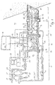
- a tunnel section is a schematic Section shown.
- At 11 is the stable mountain range referred to, from which a tunnel 13 in the problematic mountain zone 15 with high water pressure is advanced.
- the tunnel 13 has three areas: the atmospheric area 17, the lock area 19 and the high pressure area 21.
- the high pressure area 21 is partly in the stable mountains 11, partly in the problematic Mountain zone 15 and is driven by the tunnel 13 increased.
- the atmospheric area 17 is accessible by mining.
- the High-pressure area 21, however, is filled with water 25.
- the Lock 26 is halfway with water between gates 23 and 23 ' 25 shown filled.
- the lock area 19 is included Water 25 fillable and pressurizable to counteract it To be able to open high pressure area 21.
- the lock area 19 can also be emptied and the pressure in the lock area 19 equalizable to match the atmospheric range 17 to be able to open.
- the water 25 is guided in a circuit 32.
- the Water circuit 32 can have a high pressure area 32 'on the Driving side of the tunnel 13 and an area 32 "with lower pressure in the atmospheric area of the gallery 13 exhibit.
- the water pressure in the high pressure area is due to High pressure pumps 33 built. These pump the water 25 over the line 35 in the pressurized water Adit area 21.
- Water 25 flows from line 39 High pressure area 21 back to atmospheric area 17. With a valve 41, the pressure is reduced at most.
- This back-flowing water 25 has impurities, which in the settling or cleaning containers 31, 31 ' getting cleaned.
- a fresh water supply line is connected to the circuit 32 43 connected to a possible Compensate for water loss. The fresh water comes with a Pump, not shown, pumped into the circuit.
- Water 25 is filled with a pump 42 to fill the lock 26 from a chamber 44 which the water 25 of the Lock area 19 summarizes, via the line 45 in this Area filled in.
- the air escapes from the lock 26 via line 46 into chamber 44.
- the valves 48,48 ' closed.
- the lock 26 pressurized until the pressure in the high pressure area 21 corresponds.
- the Valve 53 reduces the water pressure in the return line 51 the cleaning containers 31, 31 'and build the pumps 33 the pressure in the high pressure area 32 'of the lock Circuit 32 on.
- the print can also have a one Valve lockable connecting line between the High pressure area 21 and the lock area 19 constructed become.
- a gate 23 "(shown in dashed lines) in the High pressure area 21 is provided. If one of the gates 23, 23 ' fail, can replace the defective gate with the 23 "gate and the lock area 19 relocated between the gates 23 'and 23 " or extended to the area between the gates 23 and 23 " become. However, this also requires the necessary Connections for water management 25, the Power supply and control in the appropriate Areas are provided which are not shown in FIG. 1 are shown.
- the tunnel advance i.e. the mining of the stone 11.15 and the installation of tunnel tube pieces 71 can be tried and tested Way done.
- machines such as the drill 73, the Transport devices 47,47 ', the transfer machine for the Tunnel pipes and drilling and injection machines (not shown), remote controlled to the necessity of the Avoid people in high pressure area 21.
- the machines 73, 47, 47 ' are controlled by atmospheric range. Many processes are through one Computer in the machine 73,47,47 'robotically controllable and only have to be monitored from a control center 29.
- the machine 73, 47, 47 'can operate from the control center 29 can also be controlled and corrected in a targeted manner.
- There is one Good visibility in the high pressure area 21 is an advantage.
- video cameras 75 on the drill 73 take up the environment. Your Images are sent via a line 77 to the control center 29 transmitted.
- the information and control commands can e.g. also via radio or other electromagnetic waves be transmitted.
- the supervision the processes in the high pressure area 29 can e.g. also by means of Echo sounder or radar technology happen to even stronger ones Turbidity 63 to be able to work.
- FIG. 2 shows a schematic floor plan of a possible Arrangement of two parallel lugs 13 'and 13 ".
- In this Caverns 80 are, for example, the energy supply 27 Central 29 for monitoring and controlling the machines that Cleaning container 31,31 'and others by people too operating devices to support the construction work in the High pressure area 21 and the transport through the Lock area 19 housed.
- the Lock area 19 is with a sliding gate 85 against the High pressure area 21 can be sealed off.
- the lock area is 19 with a sliding gate 87 in two locks 83 and 89 divisible.
- the second lock 89 is with a Side gallery 97 designed larger than the lock 83 to a larger transport volume with lock filling to cope with and to have enough space for maneuvering to offer.
- the lengths of the locks 83.89 are at least suitable for the tunnel boring machine 73 'or the longest the necessary machine.
- the high pressure area 21 is included a side lug 99 to make room for parking Rescue machine 101 for withdrawing a defective machine and / or to park other machines.
- the tunnel 13 ' is not in the problematic mountain zone driven, it is not yet under the influence of the the high water pressure prevailing there.
- the stable rock 11 protects the stud 13 'from the water pressure. Therefore can the gates 81, 85, 87 are open as shown and also in the high pressure area 21 there are atmospheric conditions.
- the stud 13 "has the identical structure as the stud 13 'on. With three gates 81 ', 87', 85 'are two locks 83 ', 89' between the atmospheric area 17 and the High pressure area 21 is formed. The second lock 89 'points a side gallery 97 '.
- the tunnel tunnel 91 ' has a side lug 99 '. In contrast to the tunnel 13 'is the tunnel 13 "into the problematic mountain zone 15 advanced. Therefore at least one of the gates has to be 81 ', 87', 85 'closed and the high pressure region 21 with Water 25 should be filled.
- the lock 83 ' can in this state be filled or emptied.
- the water to fill the Lock 83 in gallery 13 ' is the same as the water for Filling the lock 83 'in the gallery 13 ", i.e. filling it either lock 83 or lock 83 '.
- the cooling lines are another safety precaution 95.95 'in the icing areas 93.93'. In critical Situations through this precaution are another, not mechanical closure of the studs 13 ', 13 "available. This closure of the stud 13 ', 13 "by icing the Icing area 93.93 'enables e.g. if spilled the lock area 19 a repair of the locks 83.83 ', 89.89' and the lock gates 81.87.85.81 ', 87', 85 '.
- the tunnel 9 ' is in the area of problematic Mountain zone 15 with prefabricated pipe elements 71 ' lined. These are according to the rock pressure designed and secure the tunnel 13 "from rock collapse.
- a reinforcing and sealing coat is around 105 created. Thanks to the 13 "stud in the definite size, stands for that necessary drilling and injection work a lot of space Available. The drilling or injection machines 107 can therefore work at a large angle to the tunnel axis, what shortens the necessary drilling length.
- the finished tunnel is in one section shown.
- the first tunnel tube 104 was from Tübingringen 71 'compiled during tunneling. This forms one Temporary support of the mountains 15 under high pressure conditions the inner ring 108 made of pumped concrete built in, which withstands the water pressure, even if the Tunnel tube is open against the atmospheric area. The sealing happens e.g. with a waterproofing membrane between Tübing and inner ring.
- Tunnel tubes 104 and 108 After piercing the tunnel 13 "and finishing the Tunnel tubes 104 and 108 are the machines from the Tunnel tube 108 in the problematic mountain zone 15 removed and the pressure in the tunnel becomes slow and controlled degradation. Changes in tunnel tube 108 are monitored. In the event of water ingress, the pressure can be applied immediately raised again, the damage thereafter under Fixed high pressure conditions and reinforced the leak and be sealed. After successfully reducing the pressure in tunnel tube 108 may be under atmospheric conditions the final expansion begins.
Landscapes
- Engineering & Computer Science (AREA)
- Mining & Mineral Resources (AREA)
- Environmental & Geological Engineering (AREA)
- Life Sciences & Earth Sciences (AREA)
- General Life Sciences & Earth Sciences (AREA)
- Geochemistry & Mineralogy (AREA)
- Geology (AREA)
- Excavating Of Shafts Or Tunnels (AREA)
- Underground Structures, Protecting, Testing And Restoring Foundations (AREA)
- Conveying And Assembling Of Building Elements In Situ (AREA)
- Lining And Supports For Tunnels (AREA)
- Aerodynamic Tests, Hydrodynamic Tests, Wind Tunnels, And Water Tanks (AREA)
Claims (15)
- Procédé pour la fabrication d'un tunnel pouvant être emprunté à pied et/ou carrossable dans un massif rocheux (15) avec pression d'eau, procédé pour lequel une galerie (13, 13', 13") est creusée par abattage mécanique de roches sous terre, les roches abattues sont évacuées par transport et la galerie (13, 13', 13") est étanchéfiée contre la pression de l'eau, pour lequel est aménagées une zone de haute pression (21) et une zone atmosphérique (17) de la galerie et au moins une écluse entre la zone de haute pression (21) et la zone atmosphérique (17) au moyen de portes résistantes à la pression (23, 23', 23" ; 81, 87, 85 ; 81', 87', 85'), la zone de haute pression étant mise à une contre-pression qui correspond approximativement à la pression de l'eau du massif rocheux (15), et pour lequel l'abattage et l'évacuation des roches (15) par transport se fait à une contre-pression qui correspond approximativement à la pression de l'eau du massif rocheux (15), caractérisé en ce que l'étanchéification de la galerie (13, 13', 13") est réalisée à une contre-pression dans la galerie (13, 13', 13") qui correspond approximativement à la pression de l'eau du massif rocheux (15).
- Procédé selon la revendication 1, caractérisé en ce que l'écluse (26) ou les écluses (83, 89 ; 83', 89') sont fabriquées dans la roche solide (11) dans la galerie (13, 13', 13"), un tronçon de galerie (91, 91') est mis sous pression au-delà de l'écluse (26 ; 83, 89 ; 83', 89') et ensuite la galerie (13, 13', 13") est creusée à partir de la roche solide (11) dans le massif rocheux (15) présentant la pression de l'eau (15).
- Procédé selon l'une des revendications 1 ou 2, caractérisé en ce que la contre-pression est constituée dans un liquide qui remplit en grande partie la galerie (13, 13', 13"), en particulier dans de l'eau (25).
- Procédé selon l'une des revendications 1 à 3, caractérisé en ce que la contre-pression dans la galerie (13, 13', 13") est dimensionnée supérieure à la pression de l'eau dans le massif rocheux (15).
- Procédé selon l'une des revendications 1 à 4, caractérisé en ce qu'un premier boyau de tunnel (104) est posé dans des conditions de haute pression.
- Procédé selon l'une des revendications 1 à 5, caractérisé en ce que la galerie (13, 13', 13") est étanchéifiée dans des conditions de haute pression.
- Procédé selon la revendication 6, caractérisé en ce que l'étanchéification de la galerie (13, 13', 13") se fait avec un anneau intérieur (108) dimensionné selon la pression hydrostatique.
- Procédé selon l'une des revendications 3 à 7, caractérisé en ce que le liquide (25) est guidé dans un circuit (32) pour le nettoyer des impuretés (63) qui le troublent.
- Procédé selon la revendication 8, caractérisé en ce que le nettoyage du liquide (25) se fait en milieu atmosphérique (17) et le liquide nettoyé (25) est pompé dans la galerie (13) au moyen de pompes haute pression (33).
- Procédé selon l'une des revendications 1 à 9, caractérisé en ce que la commande et le contrôle (29) des travaux de construction se fait dans la zone à haute pression (21) à partir de la zone atmosphérique (17) et que l'on travaille dans la zone à haute pression (21) avec des appareils et des machines télécommandées (47, 47', 73, 73', 73", 101, 107).
- Procédé selon l'une des revendications 1 à 10, caractérisé en ce que les roches abattues (11, 15) sont broyées dans la zone à haute pression et sont transportées dans la zone atmosphérique (17) par des tuyauteries.
- Procédé selon l'une des revendications 5 à 11, caractérisé en ce que le premier boyau du tunnel (104) est constitué par des morceaux de tube (71') qui peuvent être assemblés à partir de plusieurs parties.
- Procédé selon l'une des revendications 3 à 12, caractérisé en ce qu'un agent floculant est mélangé au liquide (25).
- Procédé selon l'une des revendications 3 à 13, caractérisé en ce que le liquide (25) est surrefroidi dans un tronçon de galerie (93. 93') et est donc congelé.
- Procédé selon l'une des revendications 1 à 14, caractérisé en ce que pour vider l'écluse (26 ; 83, 89 ; 83', 89') le liquide est pompé ou laissé hors de l'écluse (26 ; 83, 89 ; 83', 89') dans un grand compartiment correspondant (44 ; 83', 89' ; 83 ; 89) et que pour remplir l'écluse (26 ; 83, 89 ; 83', 89') le liquide (25) est laissé ou pompé du compartiment (44 ; 83', 89' ; 83 ; 89) dans l'écluse (26 ; 83, 89 ; 83', 89').
Priority Applications (5)
| Application Number | Priority Date | Filing Date | Title |
|---|---|---|---|
| EP97810624A EP0899422B1 (fr) | 1997-09-02 | 1997-09-02 | Procédé pour la construction d'un tunnel |
| AT97810624T ATE254238T1 (de) | 1997-09-02 | 1997-09-02 | Verfahren zur erstellung eines tunnels |
| DE59711002T DE59711002D1 (de) | 1997-09-02 | 1997-09-02 | Verfahren zur Erstellung eines Tunnels |
| US09/145,389 US6089791A (en) | 1997-09-02 | 1998-09-01 | Tunnel construction method |
| JP10248314A JPH11131972A (ja) | 1997-09-02 | 1998-09-02 | トンネル構築方法 |
Applications Claiming Priority (1)
| Application Number | Priority Date | Filing Date | Title |
|---|---|---|---|
| EP97810624A EP0899422B1 (fr) | 1997-09-02 | 1997-09-02 | Procédé pour la construction d'un tunnel |
Publications (2)
| Publication Number | Publication Date |
|---|---|
| EP0899422A1 EP0899422A1 (fr) | 1999-03-03 |
| EP0899422B1 true EP0899422B1 (fr) | 2003-11-12 |
Family
ID=8230364
Family Applications (1)
| Application Number | Title | Priority Date | Filing Date |
|---|---|---|---|
| EP97810624A Expired - Lifetime EP0899422B1 (fr) | 1997-09-02 | 1997-09-02 | Procédé pour la construction d'un tunnel |
Country Status (5)
| Country | Link |
|---|---|
| US (1) | US6089791A (fr) |
| EP (1) | EP0899422B1 (fr) |
| JP (1) | JPH11131972A (fr) |
| AT (1) | ATE254238T1 (fr) |
| DE (1) | DE59711002D1 (fr) |
Cited By (2)
| Publication number | Priority date | Publication date | Assignee | Title |
|---|---|---|---|---|
| CN101975066A (zh) * | 2010-10-09 | 2011-02-16 | 河南省煤层气开发利用有限公司 | 煤岩巷快速掘进的方法 |
| CN107939408A (zh) * | 2017-10-26 | 2018-04-20 | 燕山大学 | 一种隧道挖掘并联驱动装置 |
Families Citing this family (5)
| Publication number | Priority date | Publication date | Assignee | Title |
|---|---|---|---|---|
| FR2870269B1 (fr) | 2004-05-12 | 2006-08-11 | Bouygues Travaux Publics Sa | Procede et dispositif pour realiser un tunnel immerge, sur un sol, sous une nappe d'eau |
| JP6416612B2 (ja) * | 2014-12-17 | 2018-10-31 | 西松建設株式会社 | 止水方法および壁体の構築方法 |
| CN107194136B (zh) * | 2017-07-31 | 2020-09-22 | 中国水利水电第七工程局成都水电建设工程有限公司 | 一种适用于多地层浅埋隧道的围岩压力计算方法 |
| CN109184716B (zh) * | 2018-11-12 | 2020-07-14 | 嘉兴麦瑞网络科技有限公司 | 一种盾构机刀盘的外置掘进组件 |
| IT202200008171A1 (it) | 2022-04-26 | 2023-10-26 | Mario Burigo | Metodo innovativo per la costruzione di tunnel sommersi |
Family Cites Families (17)
| Publication number | Priority date | Publication date | Assignee | Title |
|---|---|---|---|---|
| DE87157C (fr) * | ||||
| US360959A (en) * | 1887-04-12 | Apparatus for excavating tunnels | ||
| DE93519C (fr) * | ||||
| DE1409904A1 (de) * | 1962-04-12 | 1968-10-17 | Lorenz Dr Ing H | Verfahren zum Herstellen von Ausbruechen in wasserfuehrendem Erdreich mittels eines Vortriebschildes |
| JPS5332932A (en) * | 1976-09-08 | 1978-03-28 | Tekken Constr Co | Automatic controller of facing water pressure |
| DE2801616C3 (de) * | 1978-01-14 | 1980-07-17 | Weiss U. Co. Gmbh, 4200 Oberhausen | verfahren zum Auffahren von Strecken oder Tunneln in wasserführenden Fließböden unter Verwendung eines Druckluft-Vortriebsschildes |
| DE2926288C2 (de) * | 1979-06-29 | 1986-04-17 | Wayss & Freytag Ag, 6000 Frankfurt | Einrichtung zum Bodenabbau bei Schildvortrieben mit flüssigkeitsgestützer Ortsbrust |
| NL8002451A (nl) * | 1980-04-25 | 1981-11-16 | Stevin Volker Civil Eng | Werkwijze en werktuig voor het boren van tunnels. |
| DE3533425C1 (de) * | 1985-09-19 | 1986-10-30 | Hochtief Ag Vorm. Gebr. Helfmann, 4300 Essen | Stuetzfluessigkeitsdruckregelung fuer eine Schildvortriebsmaschine |
| CN1008827B (zh) * | 1987-05-01 | 1990-07-18 | 霍蒂夫股份公司霍夫曼兄弟公司 | 挡土罩 |
| JPH07116909B2 (ja) * | 1988-08-23 | 1995-12-18 | 株式会社小松製作所 | 水圧バランス式圧送排土シールド工法及びシールド掘進機 |
| DE3929393C1 (fr) * | 1989-09-02 | 1990-11-29 | Howaldtswerke - Deutsche Werft Ag, 2300 Kiel, De | |
| JP2657716B2 (ja) * | 1991-02-21 | 1997-09-24 | 厚一 植村 | オープンシールド掘進機の止水装置 |
| US5203614A (en) * | 1991-06-17 | 1993-04-20 | The Robbins Company | Tunneling machine having liquid balance low flow slurry system |
| FR2679959B1 (fr) * | 1991-08-02 | 1993-11-19 | Gtm Btp | Procede pour regler la pression dans la partie amont d'un tunnelier a pression de terre, et dispositif pour la mise en óoeuvre de ce procede. |
| JP2768104B2 (ja) * | 1992-01-23 | 1998-06-25 | 株式会社大林組 | 起泡剤を使用した機械式シールド掘進方法 |
| FR2694045B1 (fr) * | 1992-07-22 | 1994-10-14 | Sogea | Procédé, équipement et dispositif de génération et d'injection de mousse pour le creusement de tunnels. |
-
1997
- 1997-09-02 DE DE59711002T patent/DE59711002D1/de not_active Expired - Fee Related
- 1997-09-02 EP EP97810624A patent/EP0899422B1/fr not_active Expired - Lifetime
- 1997-09-02 AT AT97810624T patent/ATE254238T1/de not_active IP Right Cessation
-
1998
- 1998-09-01 US US09/145,389 patent/US6089791A/en not_active Expired - Fee Related
- 1998-09-02 JP JP10248314A patent/JPH11131972A/ja active Pending
Cited By (3)
| Publication number | Priority date | Publication date | Assignee | Title |
|---|---|---|---|---|
| CN101975066A (zh) * | 2010-10-09 | 2011-02-16 | 河南省煤层气开发利用有限公司 | 煤岩巷快速掘进的方法 |
| CN101975066B (zh) * | 2010-10-09 | 2013-01-23 | 河南省煤层气开发利用有限公司 | 煤岩巷快速掘进的方法 |
| CN107939408A (zh) * | 2017-10-26 | 2018-04-20 | 燕山大学 | 一种隧道挖掘并联驱动装置 |
Also Published As
| Publication number | Publication date |
|---|---|
| ATE254238T1 (de) | 2003-11-15 |
| DE59711002D1 (de) | 2003-12-18 |
| US6089791A (en) | 2000-07-18 |
| EP0899422A1 (fr) | 1999-03-03 |
| JPH11131972A (ja) | 1999-05-18 |
Similar Documents
| Publication | Publication Date | Title |
|---|---|---|
| DE1112592B (de) | Verfahren zur unterirdischen Beseitigung radioaktiver Abfallfluessigkeiten durch Einpumpen in tiefe Schaechte | |
| DE2349454A1 (de) | Fahrzeug zum abbau von gestein in einem grubenstollen | |
| EP0899422B1 (fr) | Procédé pour la construction d'un tunnel | |
| DE102007002399A1 (de) | Verfahren und Vorrichtung zur Herstellung einer verrohrten Strangbohrung | |
| EP1862637A1 (fr) | Dispositif et procédé de démarrage d'une machine à boucliers | |
| DE202018100857U1 (de) | Schildschwanz einer Tunnelbohrmaschine mit integrierten Bodengefrierrohren | |
| DE2651149C3 (de) | Abdichtverfahren beim Herstellen von Tunneltoren mittels Schildvortriebsvorrichtungen und Vorrichtung zur Durchführung des Verfahrens | |
| EP0359944B1 (fr) | Bouclier d'avancement | |
| DE4226324A1 (de) | Verfahren und einrichtung zum abbau eines untertage-vorkommens | |
| WO1993009333A1 (fr) | Tunnelier | |
| DE3741460C2 (de) | Schildvortriebseinrichtung mit einer Druckkammer zur Aufnahme eines Gaspolsters | |
| DE3627270A1 (de) | Vortriebsschild, insbesondere fuer den vortrieb mit erddruckgestuetzter ortsbrust, mit einem schneckenfoerderer fuer die bodenfoerderung | |
| DE2250635B2 (de) | Verfahren zur Herstellung eines Tunnels | |
| EP0772730B1 (fr) | Bouclier | |
| EP0273441B1 (fr) | Procédé d'évacuation de déblai | |
| DE4409049C1 (de) | Verfahren zum Ersetzen von Stützflüssigkeit durch Druckluft und Verwendung eines Hydroschildes zur Durchführung des Verfahrens | |
| WO2002040819A2 (fr) | Procede de realisation d'un sondage et machine de creusement correspondante | |
| EP0835984B1 (fr) | Procédé de substitution de liquide de soutien par air comprimé dans une machine de creusement hydraulique à bouclier | |
| WO1992013142A1 (fr) | Cellule sous-marine | |
| CH647040A5 (en) | Tunnel-driving apparatus | |
| DE102014100764B4 (de) | Vorrichtung und Verfahren zum Entfernen von Bodenmaterial vor der Druckwand einer Schildvortriebsmaschine (SVM) | |
| DE3204564A1 (de) | Vorrichtung zum auffahren eines stollens, tunnels oder dergleichen im rohrvorpressbetrieb, insbesondere zur herstellung einer nicht begehbaren rohrleitung | |
| DE3826772A1 (de) | Vortriebseinrichtung fuer den schildvortrieb oder fuer rohrvorpressbetriebe mit hydraulischer foerdereinrichtung | |
| EP0231404A1 (fr) | Bouclier de percement sous pression de terres | |
| DE4116096A1 (de) | Sicherungsverfahren fuer altlasten in form einer schraeggestellten, umlaufenden, muldenfoermigen dichtschuessel, die als abdichtung nachtraeglich darunter hergestellt wird |
Legal Events
| Date | Code | Title | Description |
|---|---|---|---|
| PUAI | Public reference made under article 153(3) epc to a published international application that has entered the european phase |
Free format text: ORIGINAL CODE: 0009012 |
|
| AK | Designated contracting states |
Kind code of ref document: A1 Designated state(s): AT CH DE ES FR GB IT LI |
|
| 17P | Request for examination filed |
Effective date: 19990626 |
|
| AKX | Designation fees paid |
Free format text: AT CH DE ES FR GB IT LI |
|
| 17Q | First examination report despatched |
Effective date: 20020712 |
|
| GRAH | Despatch of communication of intention to grant a patent |
Free format text: ORIGINAL CODE: EPIDOS IGRA |
|
| GRAS | Grant fee paid |
Free format text: ORIGINAL CODE: EPIDOSNIGR3 |
|
| GRAA | (expected) grant |
Free format text: ORIGINAL CODE: 0009210 |
|
| AK | Designated contracting states |
Kind code of ref document: B1 Designated state(s): AT CH DE ES FR GB IT LI |
|
| PG25 | Lapsed in a contracting state [announced via postgrant information from national office to epo] |
Ref country code: IT Free format text: LAPSE BECAUSE OF FAILURE TO SUBMIT A TRANSLATION OF THE DESCRIPTION OR TO PAY THE FEE WITHIN THE PRE;WARNING: LAPSES OF ITALIAN PATENTS WITH EFFECTIVE DATE BEFORE 2007 MAY HAVE OCCURRED AT ANY TIME BEFORE 2007. THE CORRECT EFFECTIVE DATE MAY BE DIFFERENT FROM THE ONE RECORDED.SCRIBED TIME-LIMIT Effective date: 20031112 Ref country code: GB Free format text: LAPSE BECAUSE OF FAILURE TO SUBMIT A TRANSLATION OF THE DESCRIPTION OR TO PAY THE FEE WITHIN THE PRESCRIBED TIME-LIMIT Effective date: 20031112 Ref country code: FR Free format text: LAPSE BECAUSE OF FAILURE TO SUBMIT A TRANSLATION OF THE DESCRIPTION OR TO PAY THE FEE WITHIN THE PRESCRIBED TIME-LIMIT Effective date: 20031112 Ref country code: ES Free format text: LAPSE BECAUSE OF FAILURE TO SUBMIT A TRANSLATION OF THE DESCRIPTION OR TO PAY THE FEE WITHIN THE PRESCRIBED TIME-LIMIT Effective date: 20031112 |
|
| REG | Reference to a national code |
Ref country code: GB Ref legal event code: FG4D Free format text: NOT ENGLISH |
|
| REG | Reference to a national code |
Ref country code: CH Ref legal event code: EP |
|
| REF | Corresponds to: |
Ref document number: 59711002 Country of ref document: DE Date of ref document: 20031218 Kind code of ref document: P |
|
| REG | Reference to a national code |
Ref country code: CH Ref legal event code: NV Representative=s name: RIEDERER HASLER & PARTNER PATENTANWAELTE AG |
|
| GBV | Gb: ep patent (uk) treated as always having been void in accordance with gb section 77(7)/1977 [no translation filed] |
Effective date: 20031112 |
|
| PGFP | Annual fee paid to national office [announced via postgrant information from national office to epo] |
Ref country code: DE Payment date: 20040907 Year of fee payment: 8 |
|
| PLBE | No opposition filed within time limit |
Free format text: ORIGINAL CODE: 0009261 |
|
| STAA | Information on the status of an ep patent application or granted ep patent |
Free format text: STATUS: NO OPPOSITION FILED WITHIN TIME LIMIT |
|
| 26N | No opposition filed |
Effective date: 20040813 |
|
| EN | Fr: translation not filed | ||
| PG25 | Lapsed in a contracting state [announced via postgrant information from national office to epo] |
Ref country code: DE Free format text: LAPSE BECAUSE OF NON-PAYMENT OF DUE FEES Effective date: 20060401 |
|
| PGFP | Annual fee paid to national office [announced via postgrant information from national office to epo] |
Ref country code: AT Payment date: 20060914 Year of fee payment: 10 |
|
| PGFP | Annual fee paid to national office [announced via postgrant information from national office to epo] |
Ref country code: CH Payment date: 20070913 Year of fee payment: 11 |
|
| PG25 | Lapsed in a contracting state [announced via postgrant information from national office to epo] |
Ref country code: AT Free format text: LAPSE BECAUSE OF NON-PAYMENT OF DUE FEES Effective date: 20070902 |
|
| REG | Reference to a national code |
Ref country code: CH Ref legal event code: PL |
|
| PG25 | Lapsed in a contracting state [announced via postgrant information from national office to epo] |
Ref country code: LI Free format text: LAPSE BECAUSE OF NON-PAYMENT OF DUE FEES Effective date: 20080930 Ref country code: CH Free format text: LAPSE BECAUSE OF NON-PAYMENT OF DUE FEES Effective date: 20080930 |