EP0899422B1 - Method of constructing a tunnel - Google Patents
Method of constructing a tunnel Download PDFInfo
- Publication number
- EP0899422B1 EP0899422B1 EP97810624A EP97810624A EP0899422B1 EP 0899422 B1 EP0899422 B1 EP 0899422B1 EP 97810624 A EP97810624 A EP 97810624A EP 97810624 A EP97810624 A EP 97810624A EP 0899422 B1 EP0899422 B1 EP 0899422B1
- Authority
- EP
- European Patent Office
- Prior art keywords
- pressure
- gallery
- tunnel
- lock
- water
- Prior art date
- Legal status (The legal status is an assumption and is not a legal conclusion. Google has not performed a legal analysis and makes no representation as to the accuracy of the status listed.)
- Expired - Lifetime
Links
- 238000000034 method Methods 0.000 title claims description 26
- XLYOFNOQVPJJNP-UHFFFAOYSA-N water Substances O XLYOFNOQVPJJNP-UHFFFAOYSA-N 0.000 claims abstract description 67
- 239000011435 rock Substances 0.000 claims description 13
- 239000012530 fluid Substances 0.000 claims description 10
- 238000010276 construction Methods 0.000 claims description 7
- 238000007789 sealing Methods 0.000 claims description 5
- 238000012544 monitoring process Methods 0.000 claims description 4
- 239000000356 contaminant Substances 0.000 claims description 2
- 230000002706 hydrostatic effect Effects 0.000 claims description 2
- 239000000565 sealant Substances 0.000 claims description 2
- 230000015572 biosynthetic process Effects 0.000 claims 8
- 238000009412 basement excavation Methods 0.000 claims 2
- 238000004140 cleaning Methods 0.000 abstract description 8
- 239000007788 liquid Substances 0.000 description 14
- 238000005553 drilling Methods 0.000 description 7
- 238000002347 injection Methods 0.000 description 5
- 239000007924 injection Substances 0.000 description 5
- 230000005641 tunneling Effects 0.000 description 5
- 239000006260 foam Substances 0.000 description 4
- 239000013505 freshwater Substances 0.000 description 4
- 239000000463 material Substances 0.000 description 4
- 238000005065 mining Methods 0.000 description 4
- 239000010802 sludge Substances 0.000 description 3
- 230000015556 catabolic process Effects 0.000 description 2
- 238000001816 cooling Methods 0.000 description 2
- 230000002950 deficient Effects 0.000 description 2
- 230000000694 effects Effects 0.000 description 2
- 238000005516 engineering process Methods 0.000 description 2
- 230000002349 favourable effect Effects 0.000 description 2
- 238000005192 partition Methods 0.000 description 2
- 230000002093 peripheral effect Effects 0.000 description 2
- 239000000654 additive Substances 0.000 description 1
- 238000006731 degradation reaction Methods 0.000 description 1
- 238000000605 extraction Methods 0.000 description 1
- 239000008394 flocculating agent Substances 0.000 description 1
- 238000005187 foaming Methods 0.000 description 1
- 230000002631 hypothermal effect Effects 0.000 description 1
- 239000012535 impurity Substances 0.000 description 1
- 238000009434 installation Methods 0.000 description 1
- 239000012528 membrane Substances 0.000 description 1
- 230000035699 permeability Effects 0.000 description 1
- 230000001376 precipitating effect Effects 0.000 description 1
- 238000007639 printing Methods 0.000 description 1
- 239000008213 purified water Substances 0.000 description 1
- 230000003014 reinforcing effect Effects 0.000 description 1
- 238000010079 rubber tapping Methods 0.000 description 1
- 238000000926 separation method Methods 0.000 description 1
- 239000000243 solution Substances 0.000 description 1
- 239000004575 stone Substances 0.000 description 1
- 230000003319 supportive effect Effects 0.000 description 1
- 230000000007 visual effect Effects 0.000 description 1
- 238000004078 waterproofing Methods 0.000 description 1
Images


Classifications
-
- E—FIXED CONSTRUCTIONS
- E21—EARTH OR ROCK DRILLING; MINING
- E21D—SHAFTS; TUNNELS; GALLERIES; LARGE UNDERGROUND CHAMBERS
- E21D9/00—Tunnels or galleries, with or without linings; Methods or apparatus for making thereof; Layout of tunnels or galleries
- E21D9/06—Making by using a driving shield, i.e. advanced by pushing means bearing against the already placed lining
-
- E—FIXED CONSTRUCTIONS
- E21—EARTH OR ROCK DRILLING; MINING
- E21D—SHAFTS; TUNNELS; GALLERIES; LARGE UNDERGROUND CHAMBERS
- E21D9/00—Tunnels or galleries, with or without linings; Methods or apparatus for making thereof; Layout of tunnels or galleries
-
- E—FIXED CONSTRUCTIONS
- E21—EARTH OR ROCK DRILLING; MINING
- E21D—SHAFTS; TUNNELS; GALLERIES; LARGE UNDERGROUND CHAMBERS
- E21D9/00—Tunnels or galleries, with or without linings; Methods or apparatus for making thereof; Layout of tunnels or galleries
- E21D9/06—Making by using a driving shield, i.e. advanced by pushing means bearing against the already placed lining
- E21D9/08—Making by using a driving shield, i.e. advanced by pushing means bearing against the already placed lining with additional boring or cutting means other than the conventional cutting edge of the shield
Definitions
- the present invention relates to a method for Creation of a walkable and / or navigable tunnel in one Mountains with water pressure according to the generic term of Claim 1.
- EP-A-0 580 510 describes a method for digging underground and known under atmospheric conditions.
- a drilling tool is used in which Foam under pressure by a majority of Injection orifices are injected, which Injection orifices in a rear partition Pile chamber, in front of and behind a drilling plate, on the Clearing auger and on the peripheral shield are arranged.
- the process is characterized by that a foaming solution and air into the drilling tool is transported, and only there said foam under pressure is produced.
- the foam is then pressurized into the Haufwerkshunt, the hollow shaft of the drill head, in the Pile clearing auger, or under pressure towards the Injected through the peripheral shield.
- the Generation of foam can be done at the individual points can be controlled independently.
- JP-A-02058697 is known to one A tunnel boring machine behind a boring head train.
- This pile chamber is under one Water pressure set that is higher than the water pressure of the The reason is. This will make the front of the tunnel stabilized and the pile in a very dense mud transformed, which can be evacuated backwards.
- the tunnel boring machine according to WO-A-92/22732 wants Overcome disadvantages of known tunnel boring machines.
- WO-A-92/22732 has therefore taken on the task, among other things, to propose a tunnel boring machine for soft ground can be operated in "closed mode".
- the drill head in the closed mode, the drill head is pressurized.
- Prevented tunnel front by maintaining a fluid balance is created that is not to a high degree Recirculation volume of sludge and not one Separation of aggregate and mud is required.
- the machine should be able to switch quickly and easily between use in "closed mode” and one in "open mode”.
- the drill head is not in open mode pressurized and it becomes firm ground broken into.
- the tunnel boring machine has a frame and one drill head rotatable relative to the frame. Are on the drill head a plurality of drills are arranged. Between the drills heap openings are formed, which with a Drill head chamber are connected. Pile shovels in the Drill head chambers load the pile onto a conveyor. In closed mode, the machine can be in a reason be applied in which a water pressure of 1.5 to 2 bar prevails. In this mode is the one under pressure Mud a means of supporting the tunnel front. The Liquid balance, which is used to support the tunnel front is required by adding a minimal amount Reached water to the tunnel front. This allows the Tunnels dominated, the pile liquefied and the Drill head resistance can be reduced.
- a screw conveyor and a Conveyor belt inside.
- the drill head chamber is then airtight and liquid-tight by means of a partition opposite the tunnel behind the drill head completed.
- the screw conveyor has one Ziplock. Therefore the drill head chamber is under pressure settable.
- water pressures of up to about 2x 10 5 Pa can basically be managed.
- Water pressures especially high water pressures, such as those expected at the level of the projected Gotthard base tunnel in the Pioramulde at a height of approx. 130 x 10 5 Pa, pose major problems for tunnel construction. This applies all the more if the mountains are poorly compactable and have a low stability, as in the example given. The water pressure poses a huge threat to the miners, since the ingress of water can very quickly put the tunnel under water. Lowering the water pressure to reduce this risk can be very difficult depending on the permeability of the problematic mountain zone and represents a huge intervention in the natural hydraulic balance of the mountains, the effects of which cannot be estimated.
- this is carried out using a method according to Claim 1 reached. It will be under pressure standing gallery and between the pressurized Cleats and the atmospheric area by means of pressure-proof Gates set up at least one lock. Necessarily the supply and disposal of the construction site takes place in the High pressure area from an atmospheric area.
- the Lock enables the transport of material from the atmospheric range in the high pressure range and vice versa.
- the extraction and removal of the rock as well the sealing of the gallery is about one Water pressure of the mountains corresponding counter pressure in the gallery executed. This keeps the water pressure in the mountains untouched and thereby also the water balance in the Essentially unchanged. The risk of water ingress is reduced in the gallery and the extent of the resulting damage within limits held.
- a first tunnel tube e.g. a Tübing outer ring, be installed under high pressure conditions in order to to secure the tunnel continuously with the advance.
- the tunnel is advantageous under high pressure conditions sealed. This is conveniently done by one dimensioned according to the hydrostatic pressure Stollen inner ring. This can e.g. made of pump concrete within the first to receive lithostatic printing Tunnel tube can be created.
- the back pressure in the gallery is advantageously higher than that Water pressure in the problematic mountains designed to a To prevent the inflow of mountain water. This will prevents the mountain water from mountain material in the Tunnels are washed up and cloudiness becomes against the gallery walls and therefore washed out of sight.
- the liquid filling the gallery is advantageous in circulated to clean them of turbidity.
- the return flow is expediently the circulating one Liquid cleaned of cloudy contaminants and the cleaned liquid is pumped back into the gallery.
- the cleaning of the liquid advantageously takes place in atmospheric environment and becomes the purified liquid pumped into the gallery using high-pressure pumps. This can the resulting sludge under atmospheric conditions to be disposed of. Also adding additives such as Flocculants for precipitating cloudiness or Sealant for sealing the stud can be under atmospheric conditions.
- the mined rock is advantageous in the high pressure area crushed and piped into the atmospheric Area transported. This means that for the Material removal the locks are not operated and the pressure drop can be exploited to transport to support the material to be removed.
- the first tunnel tube is expediently removed during the Jacking made up of pipe sections consisting of several Parts, so-called tubing elements, can be assembled.
- This method enables the construction of the Tunnel tube made of prefabricated pipe pieces, which from behind through the constructed tunnel tube to the front end of the tunnel tube to be transported.
- the liquid in a tunnel piece is advantageous hypothermic and thereby iced over to the pressurized Adit in the problematic mountain zone from the secured and accessible under atmospheric conditions Separate tunnel area. This makes it possible to shut off the high pressure area with means that do not mechanical operability of the gates is required. It can thereby overhauling the gates as a whole or even new be set up.
- the liquid is advantageous for emptying the lock pumped out of the lock into a correspondingly large room or left, and to fill the lock the liquid left or pumped out of the room into the lock.
- the considerable Amount of liquid cannot be drained off, on the other hand the lock does not have to go through the high pressure pumps when filling be filled. This can result in fluid, time and energy be saved.
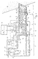
- a tunnel section is a schematic Section shown.
- At 11 is the stable mountain range referred to, from which a tunnel 13 in the problematic mountain zone 15 with high water pressure is advanced.
- the tunnel 13 has three areas: the atmospheric area 17, the lock area 19 and the high pressure area 21.
- the high pressure area 21 is partly in the stable mountains 11, partly in the problematic Mountain zone 15 and is driven by the tunnel 13 increased.
- the atmospheric area 17 is accessible by mining.
- the High-pressure area 21, however, is filled with water 25.
- the Lock 26 is halfway with water between gates 23 and 23 ' 25 shown filled.
- the lock area 19 is included Water 25 fillable and pressurizable to counteract it To be able to open high pressure area 21.
- the lock area 19 can also be emptied and the pressure in the lock area 19 equalizable to match the atmospheric range 17 to be able to open.
- the water 25 is guided in a circuit 32.
- the Water circuit 32 can have a high pressure area 32 'on the Driving side of the tunnel 13 and an area 32 "with lower pressure in the atmospheric area of the gallery 13 exhibit.
- the water pressure in the high pressure area is due to High pressure pumps 33 built. These pump the water 25 over the line 35 in the pressurized water Adit area 21.
- Water 25 flows from line 39 High pressure area 21 back to atmospheric area 17. With a valve 41, the pressure is reduced at most.
- This back-flowing water 25 has impurities, which in the settling or cleaning containers 31, 31 ' getting cleaned.
- a fresh water supply line is connected to the circuit 32 43 connected to a possible Compensate for water loss. The fresh water comes with a Pump, not shown, pumped into the circuit.
- Water 25 is filled with a pump 42 to fill the lock 26 from a chamber 44 which the water 25 of the Lock area 19 summarizes, via the line 45 in this Area filled in.
- the air escapes from the lock 26 via line 46 into chamber 44.
- the valves 48,48 ' closed.
- the lock 26 pressurized until the pressure in the high pressure area 21 corresponds.
- the Valve 53 reduces the water pressure in the return line 51 the cleaning containers 31, 31 'and build the pumps 33 the pressure in the high pressure area 32 'of the lock Circuit 32 on.
- the print can also have a one Valve lockable connecting line between the High pressure area 21 and the lock area 19 constructed become.
- a gate 23 "(shown in dashed lines) in the High pressure area 21 is provided. If one of the gates 23, 23 ' fail, can replace the defective gate with the 23 "gate and the lock area 19 relocated between the gates 23 'and 23 " or extended to the area between the gates 23 and 23 " become. However, this also requires the necessary Connections for water management 25, the Power supply and control in the appropriate Areas are provided which are not shown in FIG. 1 are shown.
- the tunnel advance i.e. the mining of the stone 11.15 and the installation of tunnel tube pieces 71 can be tried and tested Way done.
- machines such as the drill 73, the Transport devices 47,47 ', the transfer machine for the Tunnel pipes and drilling and injection machines (not shown), remote controlled to the necessity of the Avoid people in high pressure area 21.
- the machines 73, 47, 47 ' are controlled by atmospheric range. Many processes are through one Computer in the machine 73,47,47 'robotically controllable and only have to be monitored from a control center 29.
- the machine 73, 47, 47 'can operate from the control center 29 can also be controlled and corrected in a targeted manner.
- There is one Good visibility in the high pressure area 21 is an advantage.
- video cameras 75 on the drill 73 take up the environment. Your Images are sent via a line 77 to the control center 29 transmitted.
- the information and control commands can e.g. also via radio or other electromagnetic waves be transmitted.
- the supervision the processes in the high pressure area 29 can e.g. also by means of Echo sounder or radar technology happen to even stronger ones Turbidity 63 to be able to work.
- FIG. 2 shows a schematic floor plan of a possible Arrangement of two parallel lugs 13 'and 13 ".
- In this Caverns 80 are, for example, the energy supply 27 Central 29 for monitoring and controlling the machines that Cleaning container 31,31 'and others by people too operating devices to support the construction work in the High pressure area 21 and the transport through the Lock area 19 housed.
- the Lock area 19 is with a sliding gate 85 against the High pressure area 21 can be sealed off.
- the lock area is 19 with a sliding gate 87 in two locks 83 and 89 divisible.
- the second lock 89 is with a Side gallery 97 designed larger than the lock 83 to a larger transport volume with lock filling to cope with and to have enough space for maneuvering to offer.
- the lengths of the locks 83.89 are at least suitable for the tunnel boring machine 73 'or the longest the necessary machine.
- the high pressure area 21 is included a side lug 99 to make room for parking Rescue machine 101 for withdrawing a defective machine and / or to park other machines.
- the tunnel 13 ' is not in the problematic mountain zone driven, it is not yet under the influence of the the high water pressure prevailing there.
- the stable rock 11 protects the stud 13 'from the water pressure. Therefore can the gates 81, 85, 87 are open as shown and also in the high pressure area 21 there are atmospheric conditions.
- the stud 13 "has the identical structure as the stud 13 'on. With three gates 81 ', 87', 85 'are two locks 83 ', 89' between the atmospheric area 17 and the High pressure area 21 is formed. The second lock 89 'points a side gallery 97 '.
- the tunnel tunnel 91 ' has a side lug 99 '. In contrast to the tunnel 13 'is the tunnel 13 "into the problematic mountain zone 15 advanced. Therefore at least one of the gates has to be 81 ', 87', 85 'closed and the high pressure region 21 with Water 25 should be filled.
- the lock 83 ' can in this state be filled or emptied.
- the water to fill the Lock 83 in gallery 13 ' is the same as the water for Filling the lock 83 'in the gallery 13 ", i.e. filling it either lock 83 or lock 83 '.
- the cooling lines are another safety precaution 95.95 'in the icing areas 93.93'. In critical Situations through this precaution are another, not mechanical closure of the studs 13 ', 13 "available. This closure of the stud 13 ', 13 "by icing the Icing area 93.93 'enables e.g. if spilled the lock area 19 a repair of the locks 83.83 ', 89.89' and the lock gates 81.87.85.81 ', 87', 85 '.
- the tunnel 9 ' is in the area of problematic Mountain zone 15 with prefabricated pipe elements 71 ' lined. These are according to the rock pressure designed and secure the tunnel 13 "from rock collapse.
- a reinforcing and sealing coat is around 105 created. Thanks to the 13 "stud in the definite size, stands for that necessary drilling and injection work a lot of space Available. The drilling or injection machines 107 can therefore work at a large angle to the tunnel axis, what shortens the necessary drilling length.
- the finished tunnel is in one section shown.
- the first tunnel tube 104 was from Tübingringen 71 'compiled during tunneling. This forms one Temporary support of the mountains 15 under high pressure conditions the inner ring 108 made of pumped concrete built in, which withstands the water pressure, even if the Tunnel tube is open against the atmospheric area. The sealing happens e.g. with a waterproofing membrane between Tübing and inner ring.
- Tunnel tubes 104 and 108 After piercing the tunnel 13 "and finishing the Tunnel tubes 104 and 108 are the machines from the Tunnel tube 108 in the problematic mountain zone 15 removed and the pressure in the tunnel becomes slow and controlled degradation. Changes in tunnel tube 108 are monitored. In the event of water ingress, the pressure can be applied immediately raised again, the damage thereafter under Fixed high pressure conditions and reinforced the leak and be sealed. After successfully reducing the pressure in tunnel tube 108 may be under atmospheric conditions the final expansion begins.
Landscapes
- Engineering & Computer Science (AREA)
- Mining & Mineral Resources (AREA)
- Environmental & Geological Engineering (AREA)
- Life Sciences & Earth Sciences (AREA)
- General Life Sciences & Earth Sciences (AREA)
- Geochemistry & Mineralogy (AREA)
- Geology (AREA)
- Excavating Of Shafts Or Tunnels (AREA)
- Underground Structures, Protecting, Testing And Restoring Foundations (AREA)
- Conveying And Assembling Of Building Elements In Situ (AREA)
- Lining And Supports For Tunnels (AREA)
- Aerodynamic Tests, Hydrodynamic Tests, Wind Tunnels, And Water Tanks (AREA)
Abstract
Description
Die vorliegende Erfindung betrifft ein Verfahren zur Erstellung eines begeh- und/oder befahrbaren Tunnels in einem Gebirge mit Wasserdruck gemäss dem Oberbegriff des Patentanspruchs 1.The present invention relates to a method for Creation of a walkable and / or navigable tunnel in one Mountains with water pressure according to the generic term of Claim 1.
Aus der EP-A-0 580 510 ist ein Verfahren zum Graben unter Tag und unter atmosphärischen Bedingungen bekannt. Bei dem Verfahren wird ein Bohrwerkzeug eingesetzt, bei welchem Schaum unter Druck durch eine Mehrheit von Injektionsmündungen eingespritzt wird, welche Injektionsmündungen in einer hinteren Trennwand einer Haufwerkskammer, vor und hinter einem Bohrschild, auf der Haufwerkräumungsschnecke und auf dem peripheren Schild angeordnet sind. Das Verfahren zeichnet sich dadurch aus, dass eine schäumende Lösung und Luft bis ins Bohrwerkzeug befördert wird, und erst dort der besagte Schaum unter Druck erzeugt wird. Der Schaum wird dann unter Druck in die Haufwerkskammer, die Hohlwelle des Bohrkopfes, in die Haufwerkräumungsschnecke, oder unter Druck in Richtung der Außenseite durch den peripheren Schild eingespritzt. Das Generieren von Schaum kann an den einzelnen Stellen unabhängig voneinander gesteuert werden.EP-A-0 580 510 describes a method for digging underground and known under atmospheric conditions. In which A drilling tool is used in which Foam under pressure by a majority of Injection orifices are injected, which Injection orifices in a rear partition Pile chamber, in front of and behind a drilling plate, on the Clearing auger and on the peripheral shield are arranged. The process is characterized by that a foaming solution and air into the drilling tool is transported, and only there said foam under pressure is produced. The foam is then pressurized into the Haufwerkskammer, the hollow shaft of the drill head, in the Pile clearing auger, or under pressure towards the Injected through the peripheral shield. The Generation of foam can be done at the individual points can be controlled independently.
Aus der JP-A-02058697 ist bekannt, an einer Tunnelbohrmaschine eine Haufwerkskammer hinter dem Bohrkopf auszubilden. Diese Haufwerkskammer wird unter einen Wasserdruck gesetzt, der höher als der Wasserdruck des Grundes liegt. Dadurch wird die Front des Tunnels stabilisiert und das Haufwerk in einen sehr dichten Schlamm verwandelt, der nach rückwärts zwangsentleert werden kann. From JP-A-02058697 is known to one A tunnel boring machine behind a boring head train. This pile chamber is under one Water pressure set that is higher than the water pressure of the The reason is. This will make the front of the tunnel stabilized and the pile in a very dense mud transformed, which can be evacuated backwards.
Die Tunnelbohrmaschine gemäss der WO-A- 92/22732 will Nachteile bekannter Tunnelbohrmaschinen überwinden. Die WO-A-92/22732 hat sich daher unter anderem zur Aufgabe gemacht, eine Tunnelbohrmachine vorzuschlagen, die für weichen Grund in "geschlossenem Modus" betrieben werden kann. Im geschlossenen Modus ist der Bohrkopf unter Druck gesetzt. Mit einem niedrigen Schlammfluss wird einer instabilen Tunnelfront vorgebeugt, indem ein Flüssigkeitsgleichgewicht geschaffen wird, das nicht auf ein hohes Rezirkulationsvolumen von Schlamm und nicht auf eine Separation von Haufwerk und Schlamm angewiesen ist. Ferner soll die Maschine rasch und einfach wechseln können zwischen einem Einsatz in "geschlossenem Modus" und einem solchen in "offenem Modus". In offenem Modus ist der Bohrkopf nicht unter Druck gesetzt und es wird standfester Grund durchgraben.The tunnel boring machine according to WO-A-92/22732 wants Overcome disadvantages of known tunnel boring machines. WO-A-92/22732 has therefore taken on the task, among other things, to propose a tunnel boring machine for soft ground can be operated in "closed mode". in the closed mode, the drill head is pressurized. With a low mud flow becomes an unstable one Prevented tunnel front by maintaining a fluid balance is created that is not to a high degree Recirculation volume of sludge and not one Separation of aggregate and mud is required. Further the machine should be able to switch quickly and easily between use in "closed mode" and one in "open mode". The drill head is not in open mode pressurized and it becomes firm ground broken into.
Die Tunnelbohrmaschine besitzt einen Rahmen und einen gegenüber dem Rahmen drehbaren Bohrkopf. Am Bohrkopf sind eine Mehrzahl von Bohrern angeordnet. Zwischen den Bohrern sind Haufwerksöffnungen ausgebildet, die mit einer Bohrkopfkammer verbunden sind. Haufwerkschaufeln in der Bohrkopfkammer laden das Haufwerk auf einen Förderer. In geschlossenem Modus kann die Maschine in einem Grund angewandt werden, in dem ein Wasserdruck von 1,5 bis 2 bar herrscht. In diesem Modus ist der unter Druck stehende Schlamm ein Mittel zur Stützung der Tunnelfront. Das Flüssigkeitsgleichgewicht, das zur Stützung der Tunnelfront benötigt wird, wird durch die Zugabe einer minimalen Menge Wassers zur Tunnelfront erreicht. Dadurch kann die Tunnelfront beherrscht, das Haufwerk verflüssigt und der Bohrkopfwiderstand reduziert werden. The tunnel boring machine has a frame and one drill head rotatable relative to the frame. Are on the drill head a plurality of drills are arranged. Between the drills heap openings are formed, which with a Drill head chamber are connected. Pile shovels in the Drill head chambers load the pile onto a conveyor. In closed mode, the machine can be in a reason be applied in which a water pressure of 1.5 to 2 bar prevails. In this mode is the one under pressure Mud a means of supporting the tunnel front. The Liquid balance, which is used to support the tunnel front is required by adding a minimal amount Reached water to the tunnel front. This allows the Tunnels dominated, the pile liquefied and the Drill head resistance can be reduced.
In die Bohrkopfkammer reichen eine Förderschnecke und ein Förderband hinein. Für den geschlossen Modus ist das Förderband zurückziehbar. Die Bohrkopfkammer wird dann mittels einer Abschottung luft- und flüssigkeitsdicht gegenüber dem hinter dem Bohrkopf liegenden Stollen abgeschlossen. Die Förderschnecke besitzt einen Druckverschluss. Daher ist die Bohrkopfkammer unter Druck setzbar.In the drill head chamber, a screw conveyor and a Conveyor belt inside. For closed mode it is Retractable conveyor belt. The drill head chamber is then airtight and liquid-tight by means of a partition opposite the tunnel behind the drill head completed. The screw conveyor has one Ziplock. Therefore the drill head chamber is under pressure settable.
Mit derartigen Maschinen sind im Grund vorliegende Wasserdrücke bis etwa 2x 10⁵Pa bewältigbar.With such machines, water pressures of up to about 2x 10 5 Pa can basically be managed.
Wasserdrücke, insbesondere hohe Wasserdrücke, wie sie z.B. auf dem Niveau des projektierten Gotthard-Basistunnels in der Pioramulde in der Höhe von ca. 130 x 105 Pa erwartet werden, stellen den Tunnelbau vor grosse Probleme. Dies gilt umso mehr, wenn das Gebirge wie im angeführten Beispiel schlecht verdichtbar ist und eine niedrige Standfestigkeit aufweist. Der Wasserdruck stellt eine riesige Bedrohung für die Bergarbeiter dar, da ein Einbruch von Wasser allenfalls sehr rasch den Stollen unter Wasser setzen kann. Ein Absenken des Wasserdruckes zur Verminderung dieser Gefahr kann je nach Durchlässigkeit der problematischen Gebirgszone sehr schwierig sein und.stellt einen riesigen Eingriff in das natürliche hydraulische Gleichgewicht des Gebirges dar, dessen Auswirkungen unabschätzbar sind.Water pressures, especially high water pressures, such as those expected at the level of the projected Gotthard base tunnel in the Pioramulde at a height of approx. 130 x 10 5 Pa, pose major problems for tunnel construction. This applies all the more if the mountains are poorly compactable and have a low stability, as in the example given. The water pressure poses a huge threat to the miners, since the ingress of water can very quickly put the tunnel under water. Lowering the water pressure to reduce this risk can be very difficult depending on the permeability of the problematic mountain zone and represents a huge intervention in the natural hydraulic balance of the mountains, the effects of which cannot be estimated.
Es ist deshalb Aufgabe der Erfindung, ein Verfahren der erwähnten Gattung bereitzustellen, bei welchem die Gefahr für die Bergarbeiter und der Eingriff in den natürlichen Wasserhaushalt des Gebirges möglichst klein gehalten werden kann. It is therefore an object of the invention to provide a method of Provide mentioned genus, in which the danger for the miners and the encroachment on the natural The water balance in the mountains should be kept as small as possible can.
Erfindungsgemäss wird dies mit einem Verfahren gemäss Patentanspruch 1 erreicht. Es wird dazu ein unter Druck stehender Stollen und zwischen dem unter Druck stehenden Stollen und dem atmosphärischen Bereich mittels drucksicheren Toren wenigstens eine Schleuse eingerichtet. Notwendigerweise geschieht die Versorgung und Entsorgung der Baustelle im Hochdruckbereich von einem atmosphärischen Bereich aus. Die Schleuse ermöglicht den Transport von Material vom atmosphärischen Bereich in den Hochdruckbereich und umgekehrt. Der Abbau und der Abtransport des Gesteins sowie die Abdichtung des Stollens wird unter einem etwa dem Wasserdruck des Gebirges entsprechenden Gegendruck im Stollen ausgeführt. Dadurch bleibt der Wasserdruck im Gebirge unangetastet und dadurch auch der Wasserhaushalt im Wesentlichen unverändert. Die Gefahr eines Wassereinbruches in den Stollen ist verkleinert und das Ausmass des daraus entstehenden Schadens in Grenzen gehalten. Wenn der Gegendruck in einer den Stollen weitgehend ausfüllenden Flüssigkeit, insbesondere Wasser, aufgebaut wird, ist die Gefahr des Wassereinbruches gänzlich gebannt, zumal der hydraulische Druck neutralisiert ist. Der Stollen muss deshalb in der Vortriebsphase auch nicht abgedichtet sein. Dadurch kann die Abdichtung des Stollens vom Vortriebstollen aus, und daher unter günstigen räumlichen Bedingungen geschehen. Je höher der Wasserdrucks des Gebirges ist, desto mehr ist der Druckaufbau in einer Flüssigkeit einem Luftdruck vorzuziehen.According to the invention, this is carried out using a method according to Claim 1 reached. It will be under pressure standing gallery and between the pressurized Cleats and the atmospheric area by means of pressure-proof Gates set up at least one lock. Necessarily the supply and disposal of the construction site takes place in the High pressure area from an atmospheric area. The Lock enables the transport of material from the atmospheric range in the high pressure range and vice versa. The extraction and removal of the rock as well the sealing of the gallery is about one Water pressure of the mountains corresponding counter pressure in the gallery executed. This keeps the water pressure in the mountains untouched and thereby also the water balance in the Essentially unchanged. The risk of water ingress is reduced in the gallery and the extent of the resulting damage within limits held. If the back pressure in one of the tunnels largely filling liquid, especially water the risk of water ingress is completely eliminated, especially since the hydraulic pressure is neutralized. The tunnel therefore does not have to be sealed in the tunneling phase his. This can seal the stud from Tunnel, and therefore under favorable spatial Conditions happen. The higher the water pressure in the mountains is, the more pressure builds up in a liquid to prefer air pressure.
Während der Vortriebsphase genügt es grundsätzlich eine Felssicherung vorzunehmen bzw. Massnahmen zu treffen, um den auszugleichenden lithostatischen Druck aufzunehmen. Zu diesem Zweck kann eine erste Tunnelröhre, z.B. ein Tübing-Aussenring, unter Hochdruckverhältnissen eingebaut werden, um kontinuierlich mit dem Vortrieb den Stollen zu sichern.In principle, one is sufficient during the tunneling phase Make rock protection or take measures to the the lithostatic pressure to be compensated. To this A first tunnel tube, e.g. a Tübing outer ring, be installed under high pressure conditions in order to to secure the tunnel continuously with the advance.
Vorteilhaft wird der Stollen unter Hochdruckverhältnissen abgedichtet. Dies geschieht zweckmässigerweise durch einen entsprechend dem hydrostatischen Druck dimensionierten Stollen-Innenring. Dieser kann z.B. aus Pumpbeton innerhalb der ersten, den lithostatischen Druck aufnehmenden Tunnelröhre erstellt werden.The tunnel is advantageous under high pressure conditions sealed. This is conveniently done by one dimensioned according to the hydrostatic pressure Stollen inner ring. This can e.g. made of pump concrete within the first to receive lithostatic printing Tunnel tube can be created.
Vorteilhaft wird der Gegendruck im Stollen höher als der Wasserdruck im problematischen Gebirge ausgelegt, um ein Einströmen von Bergwasser zu verhindern. Dadurch wird verhindert, dass das Bergwasser Gebirgsmaterial in den Stollen schwemmt und Trübungen werden gegen die Stollenwände und daher aus dem Gesichtsfeld geschwemmt.The back pressure in the gallery is advantageously higher than that Water pressure in the problematic mountains designed to a To prevent the inflow of mountain water. This will prevents the mountain water from mountain material in the Tunnels are washed up and cloudiness becomes against the gallery walls and therefore washed out of sight.
Vorteilhaft wird die den Stollen ausfüllende Flüssigkeit in einem Kreislauf geführt, um sie von Trübungen zu reinigen. Zweckmässigerweise wird der Rücklauf der zirkulierenden Flüssigkeit von trübenden Verunreinigungen gereinigt und die gereinigte Flüssigkeit wieder in den Stollen gepumpt. Vorteilhaft geschieht die Reinigung der Flüssigkeit in atmosphärischer Umgebung und wird die gereinigte Flüssigkeit mittels Hochdruckpumpen in den Stollen gepumpt. Dadurch kann der anfallende Schlamm unter atmosphärischen Bedingungen entsorgt werden. Auch das Beigeben von Zusätzen wie Flockungsmittel zum Ausfällen von Trübungen oder Dichtungsmittel zum Abdichten des Stollens kann unter atmosphärischen Bedingungen ausgeführt werden.The liquid filling the gallery is advantageous in circulated to clean them of turbidity. The return flow is expediently the circulating one Liquid cleaned of cloudy contaminants and the cleaned liquid is pumped back into the gallery. The cleaning of the liquid advantageously takes place in atmospheric environment and becomes the purified liquid pumped into the gallery using high-pressure pumps. This can the resulting sludge under atmospheric conditions to be disposed of. Also adding additives such as Flocculants for precipitating cloudiness or Sealant for sealing the stud can be under atmospheric conditions.
Vorteilhaft geschieht die Steuerung und Überwachung der Bauarbeiten im Hochdruckbereich von einem atmosphärischen Bereich aus und wird im Hochdruckbereich mit ferngesteuerten Geräten und Maschinen gearbeitet, um die Risiken für die Bergleute möglichst gering zu halten.The control and monitoring of the Construction work in the high pressure area of an atmospheric Area and is in the high pressure area with remote controlled Equipment and machines worked to reduce the risks to the To keep miners as low as possible.
Zweckmässigerweise wird in standfestem Gebirge im Stollen die Schleuse (oder die Schleusen) erstellt, der Stollenstumpf jenseits der Schleuse unter Druck gesetzt und anschliessend der Stollen vom standfesten Gebirge aus in die Wasserdruck aufweisende, problematische Gebirgszone vorgetrieben. Dadurch wird der Stollenvortrieb in die Wasserdruck führende problematische Gebirgszone im Schutz des standfesten Gebirges unter atmosphärischen Bedingungen vorbereitet und der Anstich der problematischen Gebirgszone bereits mit einem Gegendruck im Stollen ausgeführt. Conveniently, in the stable mountains in the tunnel Lock (or the locks) created, the tunnel stump pressured beyond the lock and then the tunnel from the stable mountains into the water pressure showing problematic mountain zone. Thereby the tunnel advance will lead into the water pressure problematic mountain zone in the protection of the stable mountains prepared under atmospheric conditions and the tapping the problematic mountain zone with a back pressure executed in the gallery.
Vorteilhaft wird das abgebaute Gestein im Hochdruckbereich zerkleinert und über Rohrleitungen in den atmosphärischen Bereich transportiert. Dadurch müssen für den Materialabtransport die Schleusen nicht betätigt werden und das Druckgefälle kann ausgenutzt werden, um die Beförderung des abzutransportierenden Materials zu unterstützen.The mined rock is advantageous in the high pressure area crushed and piped into the atmospheric Area transported. This means that for the Material removal the locks are not operated and the pressure drop can be exploited to transport to support the material to be removed.
Zweckmässigerweise wird die erste Tunnelröhre während dem Vortrieb aus Rohrstücken aufgebaut, welche aus mehreren Teilen, sogenannten Tübingelementen, zusammensetzbar sind. Dieses Verfahren ermöglicht in bewährter Weise den Aufbau der Tunnelröhre aus vorfabrizierten Rohrstücken, welche von hinten durch die aufgebaute Tunnelröhre hindurch an das vordere Ende der Tunnelröhre transportiert werden.The first tunnel tube is expediently removed during the Jacking made up of pipe sections consisting of several Parts, so-called tubing elements, can be assembled. This method enables the construction of the Tunnel tube made of prefabricated pipe pieces, which from behind through the constructed tunnel tube to the front end of the tunnel tube to be transported.
Vorteilhaft wird der Flüssigkeit ein Flockungsmittel beigefügt, um Trübungen möglichst rasch auszuflocken und eine hohe Transparenz der Flüssigkeit zu erreichen. Dadurch wird die optische Überwachung der Arbeiten weniger behindert.The liquid advantageously becomes a flocculant added to flocculate turbidity as quickly as possible and a to achieve high transparency of the liquid. This will the visual surveillance of the work is less hampered.
Vorteilhaft wird die Flüssigkeit in einem Stollenstück unterkühlt und dadurch vereist, um den unter Druck stehenden Stollen in der problematischen Gebirgszone vom gesicherten und unter atmosphärischen Bedingungen betretbaren Stollenbereich zu trennen. Dadurch besteht die Möglichkeit, den Hochdruckbereich mit Mitteln abzusperren, welche keine mechanische Betriebstauglichkeit der Tore verlangt. Es können dadurch die Tore insgesamt überholt oder sogar neu eingerichtet werden.The liquid in a tunnel piece is advantageous hypothermic and thereby iced over to the pressurized Adit in the problematic mountain zone from the secured and accessible under atmospheric conditions Separate tunnel area. This makes it possible to shut off the high pressure area with means that do not mechanical operability of the gates is required. It can thereby overhauling the gates as a whole or even new be set up.
Vorteilhaft wird zum Entleeren der Schleuse die Flussigkeit aus der Schleuse in einen entsprechend grossen Raum gepumpt oder gelassen, und zum Füllen der Schleuse die Flüssigkeit aus dem Raum in die Schleuse gelassen oder gepumpt. Dadurch muss einerseits beim Entleeren der Schleuse die beträchtliche Menge an Flüssigkeit nicht abgeführt werden, andererseits muss die Schleuse beim Füllen nicht durch die Hochdruckpumpen gefüllt werden. Es kann dadurch Flüssigkeit, Zeit und Energie gespart werden.The liquid is advantageous for emptying the lock pumped out of the lock into a correspondingly large room or left, and to fill the lock the liquid left or pumped out of the room into the lock. Thereby on the one hand, the considerable Amount of liquid cannot be drained off, on the other hand the lock does not have to go through the high pressure pumps when filling be filled. This can result in fluid, time and energy be saved.
Nachfolgend werden Ausführungsbeispiele der Erfindung unter Bezugnahme auf die Figuren beschrieben. Es zeigt:
- Fig. 1
- eine schematische Darstellung eines Tunnels in einem Vertikalschnitt,
- Fig. 2
- schematische Darstellung von zwei parallelen Tunneln im Grundriss,
- Fig. 3
- einen Schnitt durch eine fertige Tunnelröhre.
- Fig. 1
- 1 shows a schematic illustration of a tunnel in a vertical section,
- Fig. 2
- schematic representation of two parallel tunnels in the floor plan,
- Fig. 3
- a section through a finished tunnel tube.
In der Figur 1 ist ein Tunnelabschnitt in einem schematischen
Schnitt dargestellt. Mit 11 ist das standfeste Gebirge
bezeichnet, von welchem aus ein Stollen 13 in die
problematische Gebirgszone 15 mit hohem Wasserdruck
vorgetrieben wird. Der Stollen 13 weist drei Bereiche auf:
den atmosphärischen Bereich 17, den Schleusenbereich 19 und
den Hochdruckbereich 21. Der Hochdruckbereich 21 ist teils im
standfesten Gebirge 11, teils in der problematischen
Gebirgszone 15 und wird mit dem Vortrieb des Stollens 13
vergrössert. Zwischen den einzelnen Bereichen 17,19,21 sind
drucksichere Panzertore 23, 23' angeordnet. Der
atmosphärische Bereich 17 ist bergmännisch begehbar. Der
Hochdruckbereich 21 hingegen ist mit Wasser 25 gefüllt. Die
Schleuse 26 ist zwischen den Toren 23 und 23' halb mit Wasser
25 gefüllt dargestellt. Der Schleusenbereich 19 ist mit
Wasser 25 füllbar und unter Druck setzbar, um ihn gegen den
Hochdruckbereich 21 öffnen zu können. Der Schleusenbereich 19
ist aber auch entleerbar und der Druck im Schleusenbereich 19
ausgleichbar, um ihn gegen den atmosphärischen Bereich 17
öffnen zu können.In Figure 1, a tunnel section is a schematic
Section shown. At 11 is the stable mountain range
referred to, from which a
Im atmosphärischen Bereich sind die unterstützenden
Einrichtungen wie Energieversorgung 27, Steuerung und
Überwachung 29 und Reinigungsbehälter 31,31' für das Wasser
25 untergebracht. Diese sind daher jederzeit unter
gewöhnlichen bergmännischen Bedingungen bedienbar.In the atmospheric area, they are supportive
Facilities such as
Das Wasser 25 ist in einem Kreislauf 32 geführt. Der
Wasserkreislauf 32 kann einen Hochdruckbereich 32' auf der
Vortriebseite des Stollens 13 und einen Bereich 32" mit
niedrigerem Druck im atmosphärischen Bereich des Stollens 13
aufweisen. Der Wasserdruck im Hochdruckbereich wird durch
Hochdruckpumpen 33 aufgebaut. Diese pumpen das Wasser 25 über
die Leitung 35 in den unter Wasserdruck stehenden
Stollenbereich 21. Über die Leitung 39 fliesst Wasser 25 vom
Hochdruckbereich 21 zurück in den atmosphärischen Bereich 17.
Mit einem Ventil 41 wird der Druck allenfalls reduziert.
Dieses zurückfliessende Wasser 25 weist Verunreinigungen auf,
welche in den Absetz- oder Reinigungsbehältern 31, 31'
gereinigt werden. An den Kreislauf 32 ist eine Frischwasser-Zuleitung
43 angeschlossen, um einen allfälligen
Wasserverlust auszugleichen. Das Frischwasser wird mit einer
nicht dargestellten Pumpe in den Kreislauf eingepumpt.The
Zum Füllen der Schleuse 26 wird mit einer Pumpe 42 Wasser 25
aus einer Kammer 44, welche das Wasser 25 des
Schleusenbereiches 19 fasst, über die Leitung 45 in diesen
Bereich eingefüllt. Die Luft aus der Schleuse 26 entweicht
über die Leitung 46 in die Kammer 44. Wenn die Schleuse 26
mit Wasser gefüllt ist, werden die Ventile 48,48'
geschlossen. Mit den Hochdruckpumpen 33 wird die Schleuse 26
unter Druck gesetzt bis dieser dem Druck im Hochdruckbereich
21 entspricht. Dann kann das Tor 23' zwischen der Schleuse 26
und dem Hochdruckbereich 21 geöffnet werden, um Güter vom
Schleusenbereich 19 in den Hochdruckbereich 21, bzw. aus dem
Hochdruckbereich 21 in den Schleusenbereich 19 zu
verschieben. Beispielsweise können die mit Tübingelementen
beladenen Wägelchen 47 im Schleusenbereich 19 mit den leeren
Wägelchen 47' im Hochdruckbereich 21 vertauscht werden.
Über die Vorlaufleitung 49 und die Rücklaufleitung 51 ist der
Kreislauf 32 auch im Schleusenbereich 19 geschlossen. Das
Ventil 53 reduziert den Wasserdruck der Rücklaufleitung 51 zu
den Reinigungsbehältern 31, 31' hin und die Pumpen 33 bauen
den Druck im schleusenseitigen Hochdruckbereich 32' des
Kreislaufs 32 auf. Der Druck kann auch über eine mit einem
Ventil verschliessbare Verbindungsleitung zwischen dem
Hochdruckbereich 21 und dem Schleusenbereich 19 aufgebaut
werden.Via the
Zum Entleeren des Schleusenbereiches 19 wird dieser vom
Kreislauf 32 durch schliessen der Ventile 53 und 55
abgetrennt. Der Druck wird über das Ventil 53 abgebaut. Hat
sich Normaldruck eingestellt, werden die Ventile 48,48' zur
Kammer 44 geöffnet. Das Wasser 25 wird in die Kammer 44
gepumpt und die Luft strömt aus der Kammer 44 in die Schleuse
26. Nun kann das Tor 23 zwischen dem atmosphärischen Bereich
17 und dem Schleusenbereich 19 geöffnet werden und ein
Austausch von Gütern stattfinden.To empty the
Zur Sicherheit ist ein Tor 23" (gestrichelt eingezeichnet) im
Hochdruckbereich 21 vorgesehen. Sollte eines der Tore 23, 23'
versagen, kann mit dem Tor 23" das defekte Tor ersetzt und
der Schleusenbereich 19 zwischen die Tore 23' und 23" verlegt
bzw. auf den Bereich zwischen den Toren 23 und 23" erweitert
werden. Dazu müssen allerdings auch die notwendigen
Anschlüsse für die Bewirtschaftung mit Wasser 25, die
Energieversorgung und die Steuerung in den entsprechenden
Bereichen vorgesehen sein, welche in der Figur 1 nicht
dargestellt sind.For security, a
Um das Druckgefälle, welches ein Tor 23,23',23" aufzunehmen
hat, zu verringern, kann auch eine Serie von Schleusen
hintereinander angeordnet werden. In einer solchen Reihe von
Schleusen muss nur die vom atmosphärischen Bereich her erste
Schleuse 26 entleert werden können. Der Druckausgleich
zwischen den Schleusen geschieht über Ventile, mit welchen
Wasser 25 von der Hochdruckseite zur Niederdruckseite eines
Tores 23,23',23"... durchgelassen wird. In order to accommodate the pressure drop which a
Im Hochdruckbereich 21 herrscht gegenüber dem Wasserdruck in
der problematischen Gebirgszone 15 ein leichter Überdruck.
Wasser 25 dringt daher ständig vom Hochdruckbereich 21 in die
problematische Gebirgszone 15 und wird durch die
Frischwasserzufuhr über die Leitung 43 mittels der
Hochdruckpumpen 33 dem Hochdruckbereich 21 des Stollens 13
wieder zugeführt. Durch den Wasserverlust an der Stollenfront
61 entsteht ein leichter Fluss Richtung problematisches
Gestein 15, welcher Trübungen 63, welche beim Abbau des
Gesteins 15 unvermeidlich entstehen, gegen die Stollenfront
61 schwemmen. Je nach Umfang dieser Strömung kann dadurch das
Wasser 25 im Stollen genügend klar bleiben, um eine
ausreichende Sicht an die Stollenfront 61 zu erlauben. Zudem
entsteht je nach den Verhältnissen ein leichter
Strömungsdruck, welcher sich günstig gegen Niederbrüche
auswirkt. Mit den Hochdruckpumpen 33 und dem Ventil 41 kann
jedoch zusätzlich eine Strömung im Kreislauf 32 eingestellt
werden. Das Frischwasser wird dann nahe der Stollenfront 61
dem Stollen 13 zugeleitet, um das benötigte Gesichtsfeld 65
mit transparentem, gereinigtem Wasser 25 zu bestücken und das
getrübte Wasser 25 aus dem Gesichtsfeld 65 wegzudrängen.
Getrübtes Wasser 25 strömt daher der Rücklaufleitung 39 zu
und wird in den Reinigungsbehältern 31,31' gereinigt. Der in
den Reinigungsbehältern 31, 31' anfallende Schlamm 67 kann
über Ventile 69,69' abgelassen und entsorgt werden.In the high-
Der Vortrieb des Tunnels, d.h. der Abbau des Gesteins 11,15
und der Einbau von Tunnelrohrstücken 71 kann in bewährter
Weise geschehen. Jedoch ist bei der Konstruktion der
Maschinen Unterseeboot-Technologie anzuwenden, damit sie dem
Wasserdruck standhalten. Zudem sind die im Hochdruckbereich
21 eingesetzten Maschinen, wie die Bohrmaschine 73, die
Transporteinrichtungen 47,47', die Versetzmaschine für die
Tunnelrohre und Bohr- und Injektionsmaschinen (nicht
eingezeichnet), ferngesteuert, um die Notwendigkeit des
Aufenthalts von Menschen im Hochdruckbereich 21 zu vermeiden.
Die Steuerung der Maschinen 73,47,47' geschieht vom
atmosphärischen Bereich aus. Viele Abläufe sind durch einen
Rechner in der Maschine 73,47,47' robotermässig steuerbar und
müssen lediglich von einer Zentrale 29 aus überwacht werden.
Von der Zentrale 29 aus kann die Maschine 73,47,47' jedoch
auch gezielt gesteuert und korrigiert werden. Dazu ist eine
gute Sicht im Hochdruckbereich 21 von Vorteil. Videokameras
75 auf der Bohrmaschine 73 nehmen die Umgebung auf. Ihre
Bilder werden über eine Leitung 77 an die Zentrale 29
übermittelt. Die Informationen und Steuerbefehle können z.B.
auch über Funk oder andere elektromagnetische Wellen
übermittelt werden. Zur Bekämpfung der Trübung 63 des Wassers
25 ist diesem ein Flockungsmittel zugesetzt. Die Überwachung
der Vorgänge im Hochdruckbereich 29 kann z.B. auch mittels
Echolot- oder Radartechnik geschehen, um auch bei stärkeren
Trübungen 63 arbeiten zu können.The tunnel advance, i.e. the mining of the stone 11.15
and the installation of
Figur 2 zeigt einen schematischen Grundriss einer möglichen
Anordnung von zwei parallel geführten Stollen 13' und 13".
Der Stollen 13' endet innerhalb des standfesten Gebirges 11,
der Stollen 13" ist bis in die problematische Gebirgszone 15
vorgetrieben. Beide Stollen 13',13" weisen einen
atmosphärischen Bereich 17, einen Schleusenbereich 19 und
einen Hochdruckbereich 21 auf, wobei beim Stollen 13' der
Hochdruckbereich 21 nicht unter Druck steht, sondern gegen
den atmosphärischen Bereich offen ist. Die atmosphärischen
Bereiche 17 beider Stollen 13',13" sind über einen
Verbindungsstollen 79 verbunden. An diesem Verbindungsstollen
79 und zwischen den beiden Stollen 13',13" ist eine Kaverne
80 für die technische Unterstützung angegliedert. In dieser
Kaverne 80 sind beispielsweise die Energieversorgung 27, die
Zentrale 29 zur Überwachung und Steuerung der Maschinen, die
Reinigungsbehälter 31,31' und weitere von Menschen zu
bedienende Geräte zur Unterstützung der Bauarbeiten im
Hochdruckbereich 21 und des Transportes durch den
Schleusenbereich 19 untergebracht.Figure 2 shows a schematic floor plan of a possible
Arrangement of two
Im Stollen 13' ist vom atmosphärischen Bereich 17 mit einem
Schiebetor 81 der Schleusenbereich 19 abtrennbar. Der
Schleusenbereich 19 ist mit einem Schiebetor 85 gegen den
Hochdruckbereich 21 abschottbar. Der Schleusenbereich 19 ist
mit einem Schiebetor 87 in zwei Schleusen 83 und 89
unterteilbar. Die zweite Schleuse 89 ist mit einem
Seitenstollen 97 grösser ausgelegt als die Schleuse 83, um
ein grösseres Transportvolumen mit einer Schleusenfullung
bewältigen zu können und um genügend Platz für Rangiermanover
zu bieten. Die Längen der Schleusen 83,89 sind wenigstens
dazu geeignet, die Tunnelbohrmaschine 73' bzw. die längste
notwendige Maschine aufzunehmen. Im Hochdruckbereich 21 ist
im Vortriebstollen 91 eine Vereisungszone 93 mit
Kühlleitungen 95 ausgerüstet. Der Hochdruckbereich 21 ist mit
einem Seitenstollen 99 versehen, um Platz zum Abstellen einer
Rettungsmaschine 101 zum Zurückziehen einer defekten Maschine
und/oder zum Abstellen von anderen Maschinen zu bieten.In the tunnel 13 'is from the
Da der Stollen 13' nicht in die problematische Gebirgszone
vorgetrieben ist, steht er noch nicht unter dem Einfluss des
dort herrschenden hohen Wasserdruckes. Der standfeste Fels 11
schützt den Stollen 13' vor dem Wasserdruck. Deshalb können
die Tore 81, 85, 87 wie eingezeichnet offen stehen und auch
im Hochdruckbereich 21 atmosphärische Bedingungen herrschen.Because the tunnel 13 'is not in the problematic mountain zone
driven, it is not yet under the influence of the
the high water pressure prevailing there. The
Der Stollen 13" weist den identischen Aufbau wie der Stollen
13' auf. Mit drei Toren 81',87',85' sind zwei Schleusen
83',89' zwischen dem atmosphärischen Bereich 17 und dem
Hochdruckbereich 21 gebildet. Die zweite Schleuse 89' weist
einen Seitenstollen 97' auf. Auch der Vortriebstollen 91'
weist einen Seitenstollen 99' auf. Im Unterschied zum Stollen
13' ist der Stollen 13" bis in die problematische Gebirgszone
15 vorgetrieben. Deshalb muss wenigstens eines der Tore
81',87',85' geschlossen und der Hochdruckbereich 21 mit
Wasser 25 gefüllt sein. In der schematischen Darstellung der
Figur 2 sind die Tore 81' und 87' vor und nach der Schleuse
83' geschlossen. Die Schleuse 83' kann in diesem Zustand
gefüllt oder entleert werden. Das Wasser zum Füllen der
Schleuse 83 im Stollen 13' ist dasselbe wie das Wasser zum
Füllen der Schleuse 83' im Stollen 13", d.h. es füllt
entweder die Schleuse 83 oder die Schleuse 83'. Die Aufgabe
der Kammer 44 von Figur 1 erfüllt für die Schleuse 83 im
Stollen 13' die entsprechende Schleuse 83' im benachbarten
Stollen 13" und umgekehrt. Zu diesem Zweck sind sie
miteinander über entsprechende, nicht eingezeichnete
Leitungen verbindbar. Ebenso sind die Schleusen 89 und 89'
miteinander verbindbar, um einen Luft bzw. Wasseraustausch
vornehmen zu können.The
Die Tore 85 und 85' sind für den Normalbetrieb nicht
notwendig. Sie sind einerseits Sicherheitsvorkehrungen,
andererseits ermöglichen Sie die Bildung unterschiedlich
grosser Schleusen 83,89;83',89'. Diese Grössenunterschiede
ermöglichen einen rationellen Betrieb der Schleusen
83,89,83',89', da meist nur das kleinere Volumen der Schleuse
83,83' entleert und gefüllt werden muss und nur in
Ausnahmefällen die grossen Schleusen 89,89' betrieben werden
müssen.
Eine weitere Sicherheitsvorkehrung sind die Kühlleitungen
95,95' in den Vereisungsbereichen 93,93'. In kritischen
Situationen steht durch diese Vorkehrung ein weiterer, nicht
mechanischer Verschluss der Stollen 13',13" zur Verfügung.
Dieser Verschluss des Stollens 13', 13" durch Vereisen des
Vereisungsbereichs 93,93' ermöglicht z.B. bei Verschüttung
des Schleusenbereiches 19 eine Reparatur der Schleusen
83,83',89,89' und der Schleusentore 81,87,85,81',87',85'.The cooling lines are another safety precaution
95.95 'in the icing areas 93.93'. In critical
Situations through this precaution are another, not
mechanical closure of the
Der Vortriebstollen 91' ist im Bereich der problematischen
Gebirgszone 15 mit vorfabrizierten Rohrelementen 71'
ausgekleidet. Diese sind entsprechend dem Gesteinsdruck
ausgelegt und sichern den Stollen 13" vor Felseinbruchen.The tunnel 9 'is in the area of
Um die aus den Rohrelementen 71' aufgebaute Tunnelröhre 104
herum wird bei Bedarf ein verstärkender und dichtender Mantel
105 erstellt. Dank dem der Stollen 13" von Anfang an in der
definitiven Grösse erstellt ist, steht für die dazu
notwendigen Bohr- und Injektionsarbeiten viel Platz zur
Verfügung. Die Bohr- bzw. Injektionsmaschinen 107 können
deshalb in einem grossen Winkel zur Tunnelachse arbeiten, was
die notwendige Bohrlänge verkürzt.Around the
In der Figur 3 ist das fertige Tunnel in einem Schnitt
dargestellt. Die erste Tunnelröhre 104 wurde aus Tübingringen
71' wahrend dem Vortrieb zusammengestellt. Dieser bildet eine
temporäre Stützung des Gebirges 15. Darin wurde anschliessend
unter Hochdruckverhältnissen der Innenring 108 aus Pumpbeton
eingebaut, welcher dem Wasserdruck standhält, auch wenn die
Tunnelröhre gegen den atmosphärischen Bereich geöffnet ist.
Die Dichtung geschieht z.B. mit einer Dichtungsbahn zwischen
Tübing und Innenring.In Figure 3, the finished tunnel is in one section
shown. The
Nach Durchstossen des Stollens 13" und Fertigstellen der
Tunnelröhren 104 und 108 werden die Maschinen aus der
Tunnelröhre 108 in der problematischen Gebirgszone 15
entfernt und der Druck im Tunnel wird langsam und
kontrolliert abgebaut. Veränderungen in der Tunnelröhre 108
werden überwacht. Bei Wassereinbrüchen kann sofort der Druck
wieder angehoben, der Schaden danach unter
Hochdruckverhältnissen behoben und die lecke Stelle verstärkt
und gedichtet werden. Nach erfolgreichem Abbau des Druckes in
der Tunnelröhre 108 kann unter atmosphärischen Bedingungen
der Endausbau beginnen.After piercing the
Claims (15)
- A method for constructing a tunnel in a formation (15) under hydraulic pressure, through which tunnel it is possible to walk and/or to drive, which method comprises the steps of driving an underground gallery (13,13',13") by mechanical rock excavation, removing of the excavated rock and sealing the gallery (13,13',13") against the hydraulic pressure, the method further comprising the steps of installing a high pressure zone (21) and an atmospheric zone (17) and of a lock between the high pressure zone (21) and the atmospheric zone (17) secured by pressure tight gates (23,23',23";81,87,85;81',87',85'), and setting the high pressure zone under a pressure corresponding approximately to the hydraulic pressure of the formation (15), wherein the excavation and removing of the rock (15) is realized under a back-pressure corresponding approximately to the hydraulic pressure of the formation (15),
characterized in that the gallery is sealed under a back-pressure in the gallery corresponding approximately to the hydraulic pressure of the formation (15). - The method according to claim 1, characterized in that it comprises the steps of: constructing the lock (26) or the locks (83,89;83', 89') within the gallery (13,13',13") in a stable formation (11), pressurizing a gallery stub on a far side of the lock, and then performing the step of driving the gallery from the stable formation into the formation subject to hydraulic pressure.
- The method according to claim 1 or 2, characterized in that the back-pressure is built up in a fluid, especially water (25), largely filling the gallery (13, 13', 13").
- The method according to one of claims 1 to 3, characterized in that the back-pressure in the gallery (13, 13', 13") is made higher than the hydraulic pressure in the formation (15).
- The method according to one of claims 1 to 4, characterized in that a first tunnel lining (104) is built in under high-pressure conditions.
- The method according to one of claims 1 to 5, characterized in that the gallery (13, 13', 13") is sealed under high-pressure conditions.
- The method according to claim 6, characterized in that the gallery (13, 13', 13") is sealed with an internal ring (108) dimensioned to match the hydrostatic pressure.
- The method according to one of claims 3 to 7, characterized in that the fluid (25) is circulated in a loop (32) in order to clean it of turbidity-causing contaminants (63).
- The method according to claim 8, characterized in that the fluid (25) is cleaned in an atmospheric environment (17) and the cleaned fluid (25) is pumped into the gallery (13) by high-pressure pumps (33).
- The method according to one of claims 1 to 9, characterized in that control and monitoring (29) of the construction tasks in the high-pressure zone (21) take place from the atmospheric zone (17), and any work in the high-pressure zone (21) is performed with remote-controlled apparatus and machinery (47, 47', 73, 73', 73", 101, 107).
- The method according to one of claims 1 to 10, characterized in that the excavated rock (11, 15) is crushed in the high-pressure zone (21) and transported via pipelines to the atmospheric zone (17).
- The method according to one of claims 5 to 11, characterized in that the first tunnel lining (104) is constructed from lining segments (71') assembled from a plurality of parts.
- A method according to one of claims 3 to 12, characterized in that at least one of a flocculant and a sealant is added to the fluid (25).
- A method according to one of claims 3 to 13, characterized in that it comprises the step of refrigerating said fluid to freeze it in a gallery segment.
- A method according to one of claims 1 to 14, characterized in that the fluid (25) from the lock (26; 83; 89; 83'; 89') is pumped or drained into a chamber (44; 83'; 89'; 83; 89) of suitable size in order to evacuate the lock (26; 83; 89; 83'; 89'), and the fluid (25) from the chamber (44; 83'; 89'; 83; 89) is drained or pumped into the lock (26; 83; 89; 83'; 89') in order to fill the lock (26; 83; 89; 83'; 89').
Priority Applications (5)
| Application Number | Priority Date | Filing Date | Title |
|---|---|---|---|
| EP97810624A EP0899422B1 (en) | 1997-09-02 | 1997-09-02 | Method of constructing a tunnel |
| AT97810624T ATE254238T1 (en) | 1997-09-02 | 1997-09-02 | METHOD FOR CREATING A TUNNEL |
| DE59711002T DE59711002D1 (en) | 1997-09-02 | 1997-09-02 | Procedure for building a tunnel |
| US09/145,389 US6089791A (en) | 1997-09-02 | 1998-09-01 | Tunnel construction method |
| JP10248314A JPH11131972A (en) | 1997-09-02 | 1998-09-02 | Tunnel constructing method |
Applications Claiming Priority (1)
| Application Number | Priority Date | Filing Date | Title |
|---|---|---|---|
| EP97810624A EP0899422B1 (en) | 1997-09-02 | 1997-09-02 | Method of constructing a tunnel |
Publications (2)
| Publication Number | Publication Date |
|---|---|
| EP0899422A1 EP0899422A1 (en) | 1999-03-03 |
| EP0899422B1 true EP0899422B1 (en) | 2003-11-12 |
Family
ID=8230364
Family Applications (1)
| Application Number | Title | Priority Date | Filing Date |
|---|---|---|---|
| EP97810624A Expired - Lifetime EP0899422B1 (en) | 1997-09-02 | 1997-09-02 | Method of constructing a tunnel |
Country Status (5)
| Country | Link |
|---|---|
| US (1) | US6089791A (en) |
| EP (1) | EP0899422B1 (en) |
| JP (1) | JPH11131972A (en) |
| AT (1) | ATE254238T1 (en) |
| DE (1) | DE59711002D1 (en) |
Cited By (2)
| Publication number | Priority date | Publication date | Assignee | Title |
|---|---|---|---|---|
| CN101975066A (en) * | 2010-10-09 | 2011-02-16 | 河南省煤层气开发利用有限公司 | Coal-rock drift quick tunnelling method |
| CN107939408A (en) * | 2017-10-26 | 2018-04-20 | 燕山大学 | A kind of tunnelling parallel drive unit |
Families Citing this family (5)
| Publication number | Priority date | Publication date | Assignee | Title |
|---|---|---|---|---|
| FR2870269B1 (en) | 2004-05-12 | 2006-08-11 | Bouygues Travaux Publics Sa | METHOD AND DEVICE FOR REALIZING AN IMMERSION TUNNEL ON A FLOOR UNDER A WATER TABLE |
| JP6416612B2 (en) * | 2014-12-17 | 2018-10-31 | 西松建設株式会社 | Water stop method and wall construction method |
| CN107194136B (en) * | 2017-07-31 | 2020-09-22 | 中国水利水电第七工程局成都水电建设工程有限公司 | Surrounding rock pressure calculation method suitable for multi-stratum shallow tunnel |
| CN109184716B (en) * | 2018-11-12 | 2020-07-14 | 嘉兴麦瑞网络科技有限公司 | External tunneling assembly of shield tunneling machine cutter head |
| IT202200008171A1 (en) | 2022-04-26 | 2023-10-26 | Mario Burigo | INNOVATIVE METHOD FOR THE CONSTRUCTION OF SUBMERGED TUNNELS |
Family Cites Families (17)
| Publication number | Priority date | Publication date | Assignee | Title |
|---|---|---|---|---|
| DE87157C (en) * | ||||
| US360959A (en) * | 1887-04-12 | Apparatus for excavating tunnels | ||
| DE93519C (en) * | ||||
| DE1409904A1 (en) * | 1962-04-12 | 1968-10-17 | Lorenz Dr Ing H | Method for creating excavations in water-bearing soil by means of a jacking shield |
| JPS5332932A (en) * | 1976-09-08 | 1978-03-28 | Tekken Constr Co | Automatic controller of facing water pressure |
| DE2801616C3 (en) * | 1978-01-14 | 1980-07-17 | Weiss U. Co. Gmbh, 4200 Oberhausen | method for driving routes or tunnels in water-bearing floating floors using a compressed air propulsion shield |
| DE2926288C2 (en) * | 1979-06-29 | 1986-04-17 | Wayss & Freytag Ag, 6000 Frankfurt | Equipment for excavation of soil in shield drives with a liquid-supported face |
| NL8002451A (en) * | 1980-04-25 | 1981-11-16 | Stevin Volker Civil Eng | Tunnel boring system for soft ground - has chamber with pressurised top part and loosening tools on shield |
| DE3533425C1 (en) * | 1985-09-19 | 1986-10-30 | Hochtief Ag Vorm. Gebr. Helfmann, 4300 Essen | Support fluid pressure control for a shield tunneling machine |
| CN1008827B (en) * | 1987-05-01 | 1990-07-18 | 霍蒂夫股份公司霍夫曼兄弟公司 | Earthguard cover |
| JPH07116909B2 (en) * | 1988-08-23 | 1995-12-18 | 株式会社小松製作所 | Water pressure balance type pumping and discharging shield method and shield machine |
| DE3929393C1 (en) * | 1989-09-02 | 1990-11-29 | Howaldtswerke - Deutsche Werft Ag, 2300 Kiel, De | |
| JP2657716B2 (en) * | 1991-02-21 | 1997-09-24 | 厚一 植村 | Water stop device of open shield machine |
| US5203614A (en) * | 1991-06-17 | 1993-04-20 | The Robbins Company | Tunneling machine having liquid balance low flow slurry system |
| FR2679959B1 (en) * | 1991-08-02 | 1993-11-19 | Gtm Btp | METHOD FOR ADJUSTING THE PRESSURE IN THE UPSTREAM PART OF AN EARTH PRESSURE TUNNEL, AND DEVICE FOR CARRYING OUT SAID METHOD. |
| JP2768104B2 (en) * | 1992-01-23 | 1998-06-25 | 株式会社大林組 | Mechanical shield excavation method using foaming agent |
| FR2694045B1 (en) * | 1992-07-22 | 1994-10-14 | Sogea | Method, equipment and device for generating and injecting foam for tunneling. |
-
1997
- 1997-09-02 DE DE59711002T patent/DE59711002D1/en not_active Expired - Fee Related
- 1997-09-02 EP EP97810624A patent/EP0899422B1/en not_active Expired - Lifetime
- 1997-09-02 AT AT97810624T patent/ATE254238T1/en not_active IP Right Cessation
-
1998
- 1998-09-01 US US09/145,389 patent/US6089791A/en not_active Expired - Fee Related
- 1998-09-02 JP JP10248314A patent/JPH11131972A/en active Pending
Cited By (3)
| Publication number | Priority date | Publication date | Assignee | Title |
|---|---|---|---|---|
| CN101975066A (en) * | 2010-10-09 | 2011-02-16 | 河南省煤层气开发利用有限公司 | Coal-rock drift quick tunnelling method |
| CN101975066B (en) * | 2010-10-09 | 2013-01-23 | 河南省煤层气开发利用有限公司 | Coal-rock drift quick tunnelling method |
| CN107939408A (en) * | 2017-10-26 | 2018-04-20 | 燕山大学 | A kind of tunnelling parallel drive unit |
Also Published As
| Publication number | Publication date |
|---|---|
| ATE254238T1 (en) | 2003-11-15 |
| DE59711002D1 (en) | 2003-12-18 |
| US6089791A (en) | 2000-07-18 |
| EP0899422A1 (en) | 1999-03-03 |
| JPH11131972A (en) | 1999-05-18 |
Similar Documents
| Publication | Publication Date | Title |
|---|---|---|
| DE1112592B (en) | Process for underground disposal of radioactive waste fluids by pumping them into deep pits | |
| DE2349454A1 (en) | VEHICLE FOR EXTRACTION OF ROCK IN A PIT | |
| EP0899422B1 (en) | Method of constructing a tunnel | |
| DE102007002399A1 (en) | Method and device for producing a cased continuous bore | |
| EP1862637A1 (en) | Device and method for a shield driving start-up and extension | |
| DE202018100857U1 (en) | Shield tail of a tunnel boring machine with integrated floor freezing pipes | |
| DE2651149C3 (en) | Sealing process when producing tunnel gates by means of shield jacking devices and device for carrying out the process | |
| EP0359944B1 (en) | Driving shield | |
| DE4226324A1 (en) | METHOD AND DEVICE FOR DEGRADING AN UNDERGROUND RESIDENCE | |
| WO1993009333A1 (en) | Tunnel-driving machine | |
| DE3741460C2 (en) | Shield propulsion device with a pressure chamber for receiving a gas cushion | |
| DE3627270A1 (en) | Driving shield, in particular for driving with a heading face supported by earth pressure, with a screw conveyor for the earth moving | |
| DE2250635B2 (en) | Method of making a tunnel | |
| EP0772730B1 (en) | Driving shield | |
| EP0273441B1 (en) | Process for discharging spoils | |
| DE4409049C1 (en) | Method of replacing the supporting liquid by compressed air and use of a hydraulic shield for carrying out the method | |
| WO2002040819A2 (en) | Method for producing a bore and advancing machine for boring | |
| EP0835984B1 (en) | Method to substitute the supporting liquid by compressed air in an hydro-shield | |
| WO1992013142A1 (en) | Under-water cell | |
| CH647040A5 (en) | Tunnel-driving apparatus | |
| DE102014100764B4 (en) | Apparatus and method for removing soil material from the pressure wall of a shield tunneling machine (SVM) | |
| DE3204564A1 (en) | Apparatus for driving galleries, tunnels or the like in pipe-advancing operation, in particular for producing an inaccessible pipeline | |
| DE3826772A1 (en) | Driving apparatus for shield driving or for pipe-jacking operations with a hydraulic conveying arrangement | |
| EP0231404A1 (en) | Earth pressure shield | |
| DE4116096A1 (en) | Rubbish dump protective method - involves using trough-shaped seal inserted by mining and sloping in one direction |
Legal Events
| Date | Code | Title | Description |
|---|---|---|---|
| PUAI | Public reference made under article 153(3) epc to a published international application that has entered the european phase |
Free format text: ORIGINAL CODE: 0009012 |
|
| AK | Designated contracting states |
Kind code of ref document: A1 Designated state(s): AT CH DE ES FR GB IT LI |
|
| 17P | Request for examination filed |
Effective date: 19990626 |
|
| AKX | Designation fees paid |
Free format text: AT CH DE ES FR GB IT LI |
|
| 17Q | First examination report despatched |
Effective date: 20020712 |
|
| GRAH | Despatch of communication of intention to grant a patent |
Free format text: ORIGINAL CODE: EPIDOS IGRA |
|
| GRAS | Grant fee paid |
Free format text: ORIGINAL CODE: EPIDOSNIGR3 |
|
| GRAA | (expected) grant |
Free format text: ORIGINAL CODE: 0009210 |
|
| AK | Designated contracting states |
Kind code of ref document: B1 Designated state(s): AT CH DE ES FR GB IT LI |
|
| PG25 | Lapsed in a contracting state [announced via postgrant information from national office to epo] |
Ref country code: IT Free format text: LAPSE BECAUSE OF FAILURE TO SUBMIT A TRANSLATION OF THE DESCRIPTION OR TO PAY THE FEE WITHIN THE PRE;WARNING: LAPSES OF ITALIAN PATENTS WITH EFFECTIVE DATE BEFORE 2007 MAY HAVE OCCURRED AT ANY TIME BEFORE 2007. THE CORRECT EFFECTIVE DATE MAY BE DIFFERENT FROM THE ONE RECORDED.SCRIBED TIME-LIMIT Effective date: 20031112 Ref country code: GB Free format text: LAPSE BECAUSE OF FAILURE TO SUBMIT A TRANSLATION OF THE DESCRIPTION OR TO PAY THE FEE WITHIN THE PRESCRIBED TIME-LIMIT Effective date: 20031112 Ref country code: FR Free format text: LAPSE BECAUSE OF FAILURE TO SUBMIT A TRANSLATION OF THE DESCRIPTION OR TO PAY THE FEE WITHIN THE PRESCRIBED TIME-LIMIT Effective date: 20031112 Ref country code: ES Free format text: LAPSE BECAUSE OF FAILURE TO SUBMIT A TRANSLATION OF THE DESCRIPTION OR TO PAY THE FEE WITHIN THE PRESCRIBED TIME-LIMIT Effective date: 20031112 |
|
| REG | Reference to a national code |
Ref country code: GB Ref legal event code: FG4D Free format text: NOT ENGLISH |
|
| REG | Reference to a national code |
Ref country code: CH Ref legal event code: EP |
|
| REF | Corresponds to: |
Ref document number: 59711002 Country of ref document: DE Date of ref document: 20031218 Kind code of ref document: P |
|
| REG | Reference to a national code |
Ref country code: CH Ref legal event code: NV Representative=s name: RIEDERER HASLER & PARTNER PATENTANWAELTE AG |
|
| GBV | Gb: ep patent (uk) treated as always having been void in accordance with gb section 77(7)/1977 [no translation filed] |
Effective date: 20031112 |
|
| PGFP | Annual fee paid to national office [announced via postgrant information from national office to epo] |
Ref country code: DE Payment date: 20040907 Year of fee payment: 8 |
|
| PLBE | No opposition filed within time limit |
Free format text: ORIGINAL CODE: 0009261 |
|
| STAA | Information on the status of an ep patent application or granted ep patent |
Free format text: STATUS: NO OPPOSITION FILED WITHIN TIME LIMIT |
|
| 26N | No opposition filed |
Effective date: 20040813 |
|
| EN | Fr: translation not filed | ||
| PG25 | Lapsed in a contracting state [announced via postgrant information from national office to epo] |
Ref country code: DE Free format text: LAPSE BECAUSE OF NON-PAYMENT OF DUE FEES Effective date: 20060401 |
|
| PGFP | Annual fee paid to national office [announced via postgrant information from national office to epo] |
Ref country code: AT Payment date: 20060914 Year of fee payment: 10 |
|
| PGFP | Annual fee paid to national office [announced via postgrant information from national office to epo] |
Ref country code: CH Payment date: 20070913 Year of fee payment: 11 |
|
| PG25 | Lapsed in a contracting state [announced via postgrant information from national office to epo] |
Ref country code: AT Free format text: LAPSE BECAUSE OF NON-PAYMENT OF DUE FEES Effective date: 20070902 |
|
| REG | Reference to a national code |
Ref country code: CH Ref legal event code: PL |
|
| PG25 | Lapsed in a contracting state [announced via postgrant information from national office to epo] |
Ref country code: LI Free format text: LAPSE BECAUSE OF NON-PAYMENT OF DUE FEES Effective date: 20080930 Ref country code: CH Free format text: LAPSE BECAUSE OF NON-PAYMENT OF DUE FEES Effective date: 20080930 |