EP0897271B1 - Method and apparatus for using, cleaning, and maintaining electrical heat sources and lighters useful in smoking systems and other apparatuses - Google Patents
Method and apparatus for using, cleaning, and maintaining electrical heat sources and lighters useful in smoking systems and other apparatuses Download PDFInfo
- Publication number
- EP0897271B1 EP0897271B1 EP97950617A EP97950617A EP0897271B1 EP 0897271 B1 EP0897271 B1 EP 0897271B1 EP 97950617 A EP97950617 A EP 97950617A EP 97950617 A EP97950617 A EP 97950617A EP 0897271 B1 EP0897271 B1 EP 0897271B1
- Authority
- EP
- European Patent Office
- Prior art keywords
- lighter
- sleeve
- heating
- cleaning
- approximately
- Prior art date
- Legal status (The legal status is an assumption and is not a legal conclusion. Google has not performed a legal analysis and makes no representation as to the accuracy of the status listed.)
- Expired - Lifetime
Links
- 238000004140 cleaning Methods 0.000 title claims description 138
- 238000000034 method Methods 0.000 title claims description 58
- 230000000391 smoking effect Effects 0.000 title claims description 44
- 235000019504 cigarettes Nutrition 0.000 claims description 205
- 238000010438 heat treatment Methods 0.000 claims description 195
- 239000000919 ceramic Substances 0.000 claims description 54
- 241000208125 Nicotiana Species 0.000 claims description 47
- 235000002637 Nicotiana tabacum Nutrition 0.000 claims description 47
- 239000000463 material Substances 0.000 claims description 43
- 239000003054 catalyst Substances 0.000 claims description 37
- 229910052751 metal Inorganic materials 0.000 claims description 33
- 239000002184 metal Substances 0.000 claims description 33
- 239000000796 flavoring agent Substances 0.000 claims description 27
- 235000019634 flavors Nutrition 0.000 claims description 27
- 239000000443 aerosol Substances 0.000 claims description 22
- NPXOKRUENSOPAO-UHFFFAOYSA-N Raney nickel Chemical compound [Al].[Ni] NPXOKRUENSOPAO-UHFFFAOYSA-N 0.000 claims description 19
- 229910000907 nickel aluminide Inorganic materials 0.000 claims description 17
- BASFCYQUMIYNBI-UHFFFAOYSA-N platinum Chemical compound [Pt] BASFCYQUMIYNBI-UHFFFAOYSA-N 0.000 claims description 16
- 238000003780 insertion Methods 0.000 claims description 14
- 230000037431 insertion Effects 0.000 claims description 14
- 229910052782 aluminium Inorganic materials 0.000 claims description 12
- 239000011248 coating agent Substances 0.000 claims description 11
- 238000000576 coating method Methods 0.000 claims description 11
- XAGFODPZIPBFFR-UHFFFAOYSA-N aluminium Chemical compound [Al] XAGFODPZIPBFFR-UHFFFAOYSA-N 0.000 claims description 10
- 239000012717 electrostatic precipitator Substances 0.000 claims description 10
- 238000012546 transfer Methods 0.000 claims description 9
- 239000012212 insulator Substances 0.000 claims description 8
- 229910052697 platinum Inorganic materials 0.000 claims description 8
- 238000009826 distribution Methods 0.000 claims description 7
- 239000006260 foam Substances 0.000 claims description 7
- 229910021326 iron aluminide Inorganic materials 0.000 claims description 5
- GWEVSGVZZGPLCZ-UHFFFAOYSA-N Titan oxide Chemical compound O=[Ti]=O GWEVSGVZZGPLCZ-UHFFFAOYSA-N 0.000 claims description 4
- UJXVAJQDLVNWPS-UHFFFAOYSA-N [Al].[Al].[Al].[Fe] Chemical compound [Al].[Al].[Al].[Fe] UJXVAJQDLVNWPS-UHFFFAOYSA-N 0.000 claims description 4
- 230000003213 activating effect Effects 0.000 claims description 4
- 230000004888 barrier function Effects 0.000 claims description 4
- 238000001816 cooling Methods 0.000 claims description 4
- 229910052878 cordierite Inorganic materials 0.000 claims description 4
- JSKIRARMQDRGJZ-UHFFFAOYSA-N dimagnesium dioxido-bis[(1-oxido-3-oxo-2,4,6,8,9-pentaoxa-1,3-disila-5,7-dialuminabicyclo[3.3.1]nonan-7-yl)oxy]silane Chemical compound [Mg++].[Mg++].[O-][Si]([O-])(O[Al]1O[Al]2O[Si](=O)O[Si]([O-])(O1)O2)O[Al]1O[Al]2O[Si](=O)O[Si]([O-])(O1)O2 JSKIRARMQDRGJZ-UHFFFAOYSA-N 0.000 claims description 4
- 239000002253 acid Substances 0.000 claims description 3
- 238000000354 decomposition reaction Methods 0.000 claims description 3
- 230000005611 electricity Effects 0.000 claims description 3
- 239000011521 glass Substances 0.000 claims description 3
- 239000012528 membrane Substances 0.000 claims description 3
- 239000012494 Quartz wool Substances 0.000 claims description 2
- 239000004411 aluminium Substances 0.000 claims description 2
- 239000003610 charcoal Substances 0.000 claims description 2
- PCHJSUWPFVWCPO-UHFFFAOYSA-N gold Chemical compound [Au] PCHJSUWPFVWCPO-UHFFFAOYSA-N 0.000 claims description 2
- 229910052737 gold Inorganic materials 0.000 claims description 2
- 239000010931 gold Substances 0.000 claims description 2
- 239000011195 cermet Substances 0.000 claims 1
- 239000011810 insulating material Substances 0.000 claims 1
- 239000003570 air Substances 0.000 description 57
- 229910045601 alloy Inorganic materials 0.000 description 35
- 239000000956 alloy Substances 0.000 description 35
- PXHVJJICTQNCMI-UHFFFAOYSA-N Nickel Chemical compound [Ni] PXHVJJICTQNCMI-UHFFFAOYSA-N 0.000 description 34
- 230000006870 function Effects 0.000 description 22
- 229910052759 nickel Inorganic materials 0.000 description 19
- XEEYBQQBJWHFJM-UHFFFAOYSA-N Iron Chemical compound [Fe] XEEYBQQBJWHFJM-UHFFFAOYSA-N 0.000 description 18
- 238000010304 firing Methods 0.000 description 15
- 125000006850 spacer group Chemical group 0.000 description 14
- MCMNRKCIXSYSNV-UHFFFAOYSA-N Zirconium dioxide Chemical compound O=[Zr]=O MCMNRKCIXSYSNV-UHFFFAOYSA-N 0.000 description 10
- 239000005022 packaging material Substances 0.000 description 9
- PNEYBMLMFCGWSK-UHFFFAOYSA-N aluminium oxide Inorganic materials [O-2].[O-2].[O-2].[Al+3].[Al+3] PNEYBMLMFCGWSK-UHFFFAOYSA-N 0.000 description 8
- 238000012423 maintenance Methods 0.000 description 8
- 229910001120 nichrome Inorganic materials 0.000 description 8
- 230000003647 oxidation Effects 0.000 description 8
- 238000007254 oxidation reaction Methods 0.000 description 8
- 239000000047 product Substances 0.000 description 8
- 239000000758 substrate Substances 0.000 description 8
- CURLTUGMZLYLDI-UHFFFAOYSA-N Carbon dioxide Chemical compound O=C=O CURLTUGMZLYLDI-UHFFFAOYSA-N 0.000 description 7
- 238000009825 accumulation Methods 0.000 description 7
- 238000005219 brazing Methods 0.000 description 7
- 238000009833 condensation Methods 0.000 description 7
- 230000005494 condensation Effects 0.000 description 7
- 230000001939 inductive effect Effects 0.000 description 7
- 230000000977 initiatory effect Effects 0.000 description 7
- 229910052742 iron Inorganic materials 0.000 description 7
- NJPPVKZQTLUDBO-UHFFFAOYSA-N novaluron Chemical compound C1=C(Cl)C(OC(F)(F)C(OC(F)(F)F)F)=CC=C1NC(=O)NC(=O)C1=C(F)C=CC=C1F NJPPVKZQTLUDBO-UHFFFAOYSA-N 0.000 description 7
- 230000008569 process Effects 0.000 description 7
- VYZAMTAEIAYCRO-UHFFFAOYSA-N Chromium Chemical compound [Cr] VYZAMTAEIAYCRO-UHFFFAOYSA-N 0.000 description 6
- 238000007792 addition Methods 0.000 description 6
- 229910052804 chromium Inorganic materials 0.000 description 6
- 239000011651 chromium Substances 0.000 description 6
- 238000002156 mixing Methods 0.000 description 6
- 230000005855 radiation Effects 0.000 description 6
- 238000003466 welding Methods 0.000 description 6
- 230000002411 adverse Effects 0.000 description 5
- 230000008901 benefit Effects 0.000 description 5
- 230000015556 catabolic process Effects 0.000 description 5
- 239000007789 gas Substances 0.000 description 5
- 238000004519 manufacturing process Methods 0.000 description 5
- 239000000779 smoke Substances 0.000 description 5
- 239000003039 volatile agent Substances 0.000 description 5
- 239000012080 ambient air Substances 0.000 description 4
- 229910002092 carbon dioxide Inorganic materials 0.000 description 4
- 238000002485 combustion reaction Methods 0.000 description 4
- 238000006731 degradation reaction Methods 0.000 description 4
- 230000007246 mechanism Effects 0.000 description 4
- 230000004044 response Effects 0.000 description 4
- 238000003860 storage Methods 0.000 description 4
- 238000007751 thermal spraying Methods 0.000 description 4
- XLYOFNOQVPJJNP-UHFFFAOYSA-N water Substances O XLYOFNOQVPJJNP-UHFFFAOYSA-N 0.000 description 4
- 229910052727 yttrium Inorganic materials 0.000 description 4
- VWQVUPCCIRVNHF-UHFFFAOYSA-N yttrium atom Chemical compound [Y] VWQVUPCCIRVNHF-UHFFFAOYSA-N 0.000 description 4
- 229910002543 FeCrAlY Inorganic materials 0.000 description 3
- 229910000943 NiAl Inorganic materials 0.000 description 3
- 238000013459 approach Methods 0.000 description 3
- 229910052799 carbon Inorganic materials 0.000 description 3
- 239000001569 carbon dioxide Substances 0.000 description 3
- 230000003197 catalytic effect Effects 0.000 description 3
- VNNRSPGTAMTISX-UHFFFAOYSA-N chromium nickel Chemical compound [Cr].[Ni] VNNRSPGTAMTISX-UHFFFAOYSA-N 0.000 description 3
- 239000012141 concentrate Substances 0.000 description 3
- 239000004020 conductor Substances 0.000 description 3
- 229910052802 copper Inorganic materials 0.000 description 3
- 239000010949 copper Substances 0.000 description 3
- 238000000151 deposition Methods 0.000 description 3
- 238000005516 engineering process Methods 0.000 description 3
- 239000000615 nonconductor Substances 0.000 description 3
- 239000002245 particle Substances 0.000 description 3
- 230000001007 puffing effect Effects 0.000 description 3
- 230000002829 reductive effect Effects 0.000 description 3
- 229910052710 silicon Inorganic materials 0.000 description 3
- 238000005476 soldering Methods 0.000 description 3
- 239000007787 solid Substances 0.000 description 3
- 239000010935 stainless steel Substances 0.000 description 3
- 229910001220 stainless steel Inorganic materials 0.000 description 3
- 239000000126 substance Substances 0.000 description 3
- 230000003746 surface roughness Effects 0.000 description 3
- 229910052726 zirconium Inorganic materials 0.000 description 3
- 229910017944 Ag—Cu Inorganic materials 0.000 description 2
- 229910000951 Aluminide Inorganic materials 0.000 description 2
- XKRFYHLGVUSROY-UHFFFAOYSA-N Argon Chemical compound [Ar] XKRFYHLGVUSROY-UHFFFAOYSA-N 0.000 description 2
- OKTJSMMVPCPJKN-UHFFFAOYSA-N Carbon Chemical compound [C] OKTJSMMVPCPJKN-UHFFFAOYSA-N 0.000 description 2
- RYGMFSIKBFXOCR-UHFFFAOYSA-N Copper Chemical compound [Cu] RYGMFSIKBFXOCR-UHFFFAOYSA-N 0.000 description 2
- 229910017372 Fe3Al Inorganic materials 0.000 description 2
- 229910002621 H2PtCl6 Inorganic materials 0.000 description 2
- 229910000990 Ni alloy Inorganic materials 0.000 description 2
- 239000003463 adsorbent Substances 0.000 description 2
- WYTGDNHDOZPMIW-RCBQFDQVSA-N alstonine Natural products C1=CC2=C3C=CC=CC3=NC2=C2N1C[C@H]1[C@H](C)OC=C(C(=O)OC)[C@H]1C2 WYTGDNHDOZPMIW-RCBQFDQVSA-N 0.000 description 2
- 230000000712 assembly Effects 0.000 description 2
- 238000000429 assembly Methods 0.000 description 2
- QVGXLLKOCUKJST-UHFFFAOYSA-N atomic oxygen Chemical compound [O] QVGXLLKOCUKJST-UHFFFAOYSA-N 0.000 description 2
- 239000006227 byproduct Substances 0.000 description 2
- 239000003990 capacitor Substances 0.000 description 2
- 238000007796 conventional method Methods 0.000 description 2
- 125000004122 cyclic group Chemical group 0.000 description 2
- 230000001351 cycling effect Effects 0.000 description 2
- 230000032798 delamination Effects 0.000 description 2
- 230000000694 effects Effects 0.000 description 2
- 230000004907 flux Effects 0.000 description 2
- 238000000227 grinding Methods 0.000 description 2
- 230000001976 improved effect Effects 0.000 description 2
- 230000006698 induction Effects 0.000 description 2
- 230000000670 limiting effect Effects 0.000 description 2
- 239000004973 liquid crystal related substance Substances 0.000 description 2
- 238000007726 management method Methods 0.000 description 2
- 238000002844 melting Methods 0.000 description 2
- 230000008018 melting Effects 0.000 description 2
- 229910052750 molybdenum Inorganic materials 0.000 description 2
- 239000001301 oxygen Substances 0.000 description 2
- 229910052760 oxygen Inorganic materials 0.000 description 2
- 230000002093 peripheral effect Effects 0.000 description 2
- 238000013033 photocatalytic degradation reaction Methods 0.000 description 2
- 239000004033 plastic Substances 0.000 description 2
- 239000011148 porous material Substances 0.000 description 2
- 239000000843 powder Substances 0.000 description 2
- 238000012545 processing Methods 0.000 description 2
- 230000001681 protective effect Effects 0.000 description 2
- 238000000197 pyrolysis Methods 0.000 description 2
- 238000005096 rolling process Methods 0.000 description 2
- 230000005236 sound signal Effects 0.000 description 2
- 238000004901 spalling Methods 0.000 description 2
- 238000005507 spraying Methods 0.000 description 2
- 230000002459 sustained effect Effects 0.000 description 2
- 239000010936 titanium Substances 0.000 description 2
- 229910052719 titanium Inorganic materials 0.000 description 2
- 238000009827 uniform distribution Methods 0.000 description 2
- 230000000007 visual effect Effects 0.000 description 2
- 229910000906 Bronze Inorganic materials 0.000 description 1
- 101100171060 Caenorhabditis elegans div-1 gene Proteins 0.000 description 1
- 229910000640 Fe alloy Inorganic materials 0.000 description 1
- PWHULOQIROXLJO-UHFFFAOYSA-N Manganese Chemical compound [Mn] PWHULOQIROXLJO-UHFFFAOYSA-N 0.000 description 1
- ZOKXTWBITQBERF-UHFFFAOYSA-N Molybdenum Chemical compound [Mo] ZOKXTWBITQBERF-UHFFFAOYSA-N 0.000 description 1
- 229910018054 Ni-Cu Inorganic materials 0.000 description 1
- 229910018481 Ni—Cu Inorganic materials 0.000 description 1
- OAICVXFJPJFONN-UHFFFAOYSA-N Phosphorus Chemical compound [P] OAICVXFJPJFONN-UHFFFAOYSA-N 0.000 description 1
- 229910001260 Pt alloy Inorganic materials 0.000 description 1
- VYPSYNLAJGMNEJ-UHFFFAOYSA-N Silicium dioxide Chemical compound O=[Si]=O VYPSYNLAJGMNEJ-UHFFFAOYSA-N 0.000 description 1
- BQCADISMDOOEFD-UHFFFAOYSA-N Silver Chemical compound [Ag] BQCADISMDOOEFD-UHFFFAOYSA-N 0.000 description 1
- RTAQQCXQSZGOHL-UHFFFAOYSA-N Titanium Chemical compound [Ti] RTAQQCXQSZGOHL-UHFFFAOYSA-N 0.000 description 1
- QCWXUUIWCKQGHC-UHFFFAOYSA-N Zirconium Chemical compound [Zr] QCWXUUIWCKQGHC-UHFFFAOYSA-N 0.000 description 1
- 230000004913 activation Effects 0.000 description 1
- 239000000654 additive Substances 0.000 description 1
- 230000001464 adherent effect Effects 0.000 description 1
- 230000001476 alcoholic effect Effects 0.000 description 1
- 230000004075 alteration Effects 0.000 description 1
- 229910052786 argon Inorganic materials 0.000 description 1
- 238000005422 blasting Methods 0.000 description 1
- 239000010974 bronze Substances 0.000 description 1
- OJIJEKBXJYRIBZ-UHFFFAOYSA-N cadmium nickel Chemical compound [Ni].[Cd] OJIJEKBXJYRIBZ-UHFFFAOYSA-N 0.000 description 1
- 238000006555 catalytic reaction Methods 0.000 description 1
- 229920002301 cellulose acetate Polymers 0.000 description 1
- 229910010293 ceramic material Inorganic materials 0.000 description 1
- 239000012700 ceramic precursor Substances 0.000 description 1
- 230000008859 change Effects 0.000 description 1
- -1 charcoal Chemical compound 0.000 description 1
- 238000005234 chemical deposition Methods 0.000 description 1
- 238000006243 chemical reaction Methods 0.000 description 1
- 238000005229 chemical vapour deposition Methods 0.000 description 1
- 229910017052 cobalt Inorganic materials 0.000 description 1
- 239000010941 cobalt Substances 0.000 description 1
- GUTLYIVDDKVIGB-UHFFFAOYSA-N cobalt atom Chemical compound [Co] GUTLYIVDDKVIGB-UHFFFAOYSA-N 0.000 description 1
- 238000004891 communication Methods 0.000 description 1
- 230000000295 complement effect Effects 0.000 description 1
- 150000001875 compounds Chemical class 0.000 description 1
- 230000008602 contraction Effects 0.000 description 1
- KUNSUQLRTQLHQQ-UHFFFAOYSA-N copper tin Chemical compound [Cu].[Sn] KUNSUQLRTQLHQQ-UHFFFAOYSA-N 0.000 description 1
- 230000007797 corrosion Effects 0.000 description 1
- 238000005260 corrosion Methods 0.000 description 1
- 230000003247 decreasing effect Effects 0.000 description 1
- 230000008021 deposition Effects 0.000 description 1
- 230000000881 depressing effect Effects 0.000 description 1
- 238000013461 design Methods 0.000 description 1
- 239000010432 diamond Substances 0.000 description 1
- 229910003460 diamond Inorganic materials 0.000 description 1
- 238000009792 diffusion process Methods 0.000 description 1
- KZHJGOXRZJKJNY-UHFFFAOYSA-N dioxosilane;oxo(oxoalumanyloxy)alumane Chemical compound O=[Si]=O.O=[Si]=O.O=[Al]O[Al]=O.O=[Al]O[Al]=O.O=[Al]O[Al]=O KZHJGOXRZJKJNY-UHFFFAOYSA-N 0.000 description 1
- 238000007599 discharging Methods 0.000 description 1
- 238000004821 distillation Methods 0.000 description 1
- 230000009977 dual effect Effects 0.000 description 1
- 238000010292 electrical insulation Methods 0.000 description 1
- 230000005674 electromagnetic induction Effects 0.000 description 1
- 230000002708 enhancing effect Effects 0.000 description 1
- 238000001125 extrusion Methods 0.000 description 1
- 230000005669 field effect Effects 0.000 description 1
- 239000010408 film Substances 0.000 description 1
- 239000012530 fluid Substances 0.000 description 1
- 239000011888 foil Substances 0.000 description 1
- 229910052839 forsterite Inorganic materials 0.000 description 1
- 239000000446 fuel Substances 0.000 description 1
- 238000005286 illumination Methods 0.000 description 1
- 230000006872 improvement Effects 0.000 description 1
- 229910001026 inconel Inorganic materials 0.000 description 1
- 229910001119 inconels 625 Inorganic materials 0.000 description 1
- 229910052738 indium Inorganic materials 0.000 description 1
- APFVFJFRJDLVQX-UHFFFAOYSA-N indium atom Chemical compound [In] APFVFJFRJDLVQX-UHFFFAOYSA-N 0.000 description 1
- 238000009434 installation Methods 0.000 description 1
- 229910000765 intermetallic Inorganic materials 0.000 description 1
- 239000007788 liquid Substances 0.000 description 1
- 238000011068 loading method Methods 0.000 description 1
- 230000005923 long-lasting effect Effects 0.000 description 1
- HCWCAKKEBCNQJP-UHFFFAOYSA-N magnesium orthosilicate Chemical compound [Mg+2].[Mg+2].[O-][Si]([O-])([O-])[O-] HCWCAKKEBCNQJP-UHFFFAOYSA-N 0.000 description 1
- 229910052748 manganese Inorganic materials 0.000 description 1
- 239000011572 manganese Substances 0.000 description 1
- WPBNNNQJVZRUHP-UHFFFAOYSA-L manganese(2+);methyl n-[[2-(methoxycarbonylcarbamothioylamino)phenyl]carbamothioyl]carbamate;n-[2-(sulfidocarbothioylamino)ethyl]carbamodithioate Chemical compound [Mn+2].[S-]C(=S)NCCNC([S-])=S.COC(=O)NC(=S)NC1=CC=CC=C1NC(=S)NC(=O)OC WPBNNNQJVZRUHP-UHFFFAOYSA-L 0.000 description 1
- 230000000873 masking effect Effects 0.000 description 1
- 238000005272 metallurgy Methods 0.000 description 1
- 150000002739 metals Chemical class 0.000 description 1
- VUZPPFZMUPKLLV-UHFFFAOYSA-N methane;hydrate Chemical compound C.O VUZPPFZMUPKLLV-UHFFFAOYSA-N 0.000 description 1
- 239000000203 mixture Substances 0.000 description 1
- 238000012986 modification Methods 0.000 description 1
- 230000004048 modification Effects 0.000 description 1
- 239000011733 molybdenum Substances 0.000 description 1
- 229910052863 mullite Inorganic materials 0.000 description 1
- 230000007935 neutral effect Effects 0.000 description 1
- 229910052758 niobium Inorganic materials 0.000 description 1
- 238000013021 overheating Methods 0.000 description 1
- 230000037361 pathway Effects 0.000 description 1
- 230000000149 penetrating effect Effects 0.000 description 1
- 230000035515 penetration Effects 0.000 description 1
- 230000000737 periodic effect Effects 0.000 description 1
- 229910052698 phosphorus Inorganic materials 0.000 description 1
- 239000011574 phosphorus Substances 0.000 description 1
- 238000005240 physical vapour deposition Methods 0.000 description 1
- 238000007750 plasma spraying Methods 0.000 description 1
- 229920000642 polymer Polymers 0.000 description 1
- 239000012716 precipitator Substances 0.000 description 1
- 230000009257 reactivity Effects 0.000 description 1
- 230000000284 resting effect Effects 0.000 description 1
- 238000007650 screen-printing Methods 0.000 description 1
- 239000000565 sealant Substances 0.000 description 1
- 230000035939 shock Effects 0.000 description 1
- 230000011664 signaling Effects 0.000 description 1
- 229910021332 silicide Inorganic materials 0.000 description 1
- 239000010703 silicon Substances 0.000 description 1
- 229910052814 silicon oxide Inorganic materials 0.000 description 1
- 229910052709 silver Inorganic materials 0.000 description 1
- 239000004332 silver Substances 0.000 description 1
- 238000005245 sintering Methods 0.000 description 1
- 241000894007 species Species 0.000 description 1
- 229910052596 spinel Inorganic materials 0.000 description 1
- 239000011029 spinel Substances 0.000 description 1
- 239000007921 spray Substances 0.000 description 1
- 238000006467 substitution reaction Methods 0.000 description 1
- 229910000601 superalloy Inorganic materials 0.000 description 1
- 238000010301 surface-oxidation reaction Methods 0.000 description 1
- 229910052715 tantalum Inorganic materials 0.000 description 1
- 238000005382 thermal cycling Methods 0.000 description 1
- 239000010409 thin film Substances 0.000 description 1
- 230000001960 triggered effect Effects 0.000 description 1
- WFKWXMTUELFFGS-UHFFFAOYSA-N tungsten Chemical compound [W] WFKWXMTUELFFGS-UHFFFAOYSA-N 0.000 description 1
- 229910052721 tungsten Inorganic materials 0.000 description 1
- 239000010937 tungsten Substances 0.000 description 1
- RUDFQVOCFDJEEF-UHFFFAOYSA-N yttrium(III) oxide Inorganic materials [O-2].[O-2].[O-2].[Y+3].[Y+3] RUDFQVOCFDJEEF-UHFFFAOYSA-N 0.000 description 1
Images


Classifications
-
- A—HUMAN NECESSITIES
- A24—TOBACCO; CIGARS; CIGARETTES; SIMULATED SMOKING DEVICES; SMOKERS' REQUISITES
- A24F—SMOKERS' REQUISITES; MATCH BOXES; SIMULATED SMOKING DEVICES
- A24F40/00—Electrically operated smoking devices; Component parts thereof; Manufacture thereof; Maintenance or testing thereof; Charging means specially adapted therefor
- A24F40/40—Constructional details, e.g. connection of cartridges and battery parts
- A24F40/46—Shape or structure of electric heating means
-
- A—HUMAN NECESSITIES
- A24—TOBACCO; CIGARS; CIGARETTES; SIMULATED SMOKING DEVICES; SMOKERS' REQUISITES
- A24F—SMOKERS' REQUISITES; MATCH BOXES; SIMULATED SMOKING DEVICES
- A24F40/00—Electrically operated smoking devices; Component parts thereof; Manufacture thereof; Maintenance or testing thereof; Charging means specially adapted therefor
- A24F40/85—Maintenance, e.g. cleaning
-
- A—HUMAN NECESSITIES
- A24—TOBACCO; CIGARS; CIGARETTES; SIMULATED SMOKING DEVICES; SMOKERS' REQUISITES
- A24F—SMOKERS' REQUISITES; MATCH BOXES; SIMULATED SMOKING DEVICES
- A24F40/00—Electrically operated smoking devices; Component parts thereof; Manufacture thereof; Maintenance or testing thereof; Charging means specially adapted therefor
- A24F40/40—Constructional details, e.g. connection of cartridges and battery parts
- A24F40/46—Shape or structure of electric heating means
- A24F40/465—Shape or structure of electric heating means specially adapted for induction heating
-
- A—HUMAN NECESSITIES
- A24—TOBACCO; CIGARS; CIGARETTES; SIMULATED SMOKING DEVICES; SMOKERS' REQUISITES
- A24F—SMOKERS' REQUISITES; MATCH BOXES; SIMULATED SMOKING DEVICES
- A24F40/00—Electrically operated smoking devices; Component parts thereof; Manufacture thereof; Maintenance or testing thereof; Charging means specially adapted therefor
- A24F40/50—Control or monitoring
- A24F40/53—Monitoring, e.g. fault detection
-
- A—HUMAN NECESSITIES
- A24—TOBACCO; CIGARS; CIGARETTES; SIMULATED SMOKING DEVICES; SMOKERS' REQUISITES
- A24F—SMOKERS' REQUISITES; MATCH BOXES; SIMULATED SMOKING DEVICES
- A24F40/00—Electrically operated smoking devices; Component parts thereof; Manufacture thereof; Maintenance or testing thereof; Charging means specially adapted therefor
- A24F40/60—Devices with integrated user interfaces
-
- F—MECHANICAL ENGINEERING; LIGHTING; HEATING; WEAPONS; BLASTING
- F23—COMBUSTION APPARATUS; COMBUSTION PROCESSES
- F23Q—IGNITION; EXTINGUISHING-DEVICES
- F23Q2/00—Lighters containing fuel, e.g. for cigarettes
- F23Q2/32—Lighters characterised by being combined with other objects
-
- F—MECHANICAL ENGINEERING; LIGHTING; HEATING; WEAPONS; BLASTING
- F23—COMBUSTION APPARATUS; COMBUSTION PROCESSES
- F23Q—IGNITION; EXTINGUISHING-DEVICES
- F23Q3/00—Igniters using electrically-produced sparks
- F23Q3/01—Hand-held lighters, e.g. for cigarettes
-
- A—HUMAN NECESSITIES
- A24—TOBACCO; CIGARS; CIGARETTES; SIMULATED SMOKING DEVICES; SMOKERS' REQUISITES
- A24F—SMOKERS' REQUISITES; MATCH BOXES; SIMULATED SMOKING DEVICES
- A24F40/00—Electrically operated smoking devices; Component parts thereof; Manufacture thereof; Maintenance or testing thereof; Charging means specially adapted therefor
- A24F40/20—Devices using solid inhalable precursors
-
- A—HUMAN NECESSITIES
- A24—TOBACCO; CIGARS; CIGARETTES; SIMULATED SMOKING DEVICES; SMOKERS' REQUISITES
- A24F—SMOKERS' REQUISITES; MATCH BOXES; SIMULATED SMOKING DEVICES
- A24F40/00—Electrically operated smoking devices; Component parts thereof; Manufacture thereof; Maintenance or testing thereof; Charging means specially adapted therefor
- A24F40/90—Arrangements or methods specially adapted for charging batteries thereof
Definitions
- the present invention further relates to commonly assigned, copending US patent applications Serial No. 08/365,952, filed December 29, 1994, issued as US patent No. 5,595,706, entitled “Aluminum Containing Iron-Base Alloys Useful as Electrical Resistance Heating Elements” (Attorney Docket No. PM 1767), to Serial No, 08/425,166, filed April 20 1995, issued as US patent No. 5,692,525, entitled £Cigarette for Electrical Smoking System" (Attorney Docket No. PM 1759A), to Serial No, 08/425,837, filed April 20 1995, issued as US patent No. 5,499,636, entitled “Cigarette for Electrical Smoking System” (Attorney Docket No.
- the present invention relates to methods and apparatuses for using, cleaning, and maintaining electrical heat sources and lighters useful in electrical smoking systems or the like.
- Previously known conventional lit cigarettes deliver flavour and aroma to the user as a result of combustion of tobacco.
- a mass of combustible material primarily tobacco, is oxidized as the result of applied heat with typical combustion temperatures in a conventional cigarette being in excess of 800°C during puffing.
- Heat is drawn through an adjacent mass of tobacco by drawing on the mouth end. During this heating, inefficient oxidation of the combustible material takes place and yields various distillation and pyrolysis products. As these products are drawn through the body of the smoking device toward the mouth of the user, they cool and condense to form the aerosol which gives the consumer the flavor and aroma associated with smoking.
- Prior alternatives to the more conventional lit cigarettes include those in which the combustible material itself does not directly provide the flavorants to the aerosol inhaled by the smoker.
- a combustible heating element typically carbonaceous in nature, is combusted to heat air as it is drawn over the heating element and through a zone which contains heat-activated elements that release a flavored aerosol. While this type of lit cigarette produces little or no sidestream smoke, it still generates products of combustion, and once lit it is not adapted to be snuffed for future use in the conventional sense.
- the preferred embodiment of the lighter of Patent No. 5,388,594 includes a plurality of metallic heaters disposed in a configuration that slidingly receives a tobacco rod portion of the cigarette.
- One of the many advantages of such smoking systems is the reusability of the lighter for numerous cigarettes.
- aerosol is generated for smoking by the smoker.
- Some portion of the generated aerosol is not delivered to the smoker and may tend to condense and form condensates on the relatively cooler individual heaters, the heater fixture, electrical connections, electronic components and other components and structures located within the cigarette-receiving cavity and/or subject to contact with the generated aerosol.
- portions of the cigarette especially portions which have been heated and therefore thermally weakened, may cling to surfaces, especially to individual heaters, after the cigarette is removed due to tight tolerances.
- Such condensation and/or cigarette remnants can alter the subjective taste of subsequent cigarettes; can block required airflow passages, especially the passageways communicating with any puff sensitive pressure drop sensor and/or with outside ambient air; can damage sensitive electronic and electrical components; and can result in protrusions, snags, etc. which could adversely affect insertion, registration and removal of cigarettes relative to the heater fixture.
- condensation is the result of the flow pattern and pressure gradient of ambient air drawn through the cigarette and the current designs of the heater assemblies.
- the heating of the cigarette tobacco produces aerosols which are then cooled to result in condensation on the surfaces of relatively cooler components.
- this heater sleeve is discarded after a certain interval, e.g. 30-60 cigarettes, and replaced with a new heater sleeve, necessitating a potentially time consuming and/or inconvenient replacement procedure by the smoker. Also, this removal of a used sleeve and installation of a new sleeve could potentially damage the cigarette heater assembly, which may be delicate.
- any cleaning of the electrical lighter with other routine maintenance procedures such as recharging of lighter batteries.
- it may be desired to perform both cleaning and recharging on a daily basis, preferably substantially contemporanously.
- it may be desirable to alert the smoker of the necessity of these functions and/or to establish these functions as prerequisites to operation of the lighter.
- an apparatus for cleaning or maintaining an electrical lighter having an interior, the lighter heating tobacco and/or a tobacco-containing material inserted into the interior to evolve flavors for delivery to a smoker, some of which evolved flavors form a condensate within the lighter comprising: a surface element for collecting condensates from a portion of the evolved flavors not delivered to a smoker; a heating element for heating the surface element to thermally liberate the collected condensates; and a controller for controlling the amount of heating of said heating element to ensure the thermal liberation of the condensates, whereby the surface element is cleaned of at least some of the condensates upon heating by said heating element.
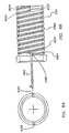
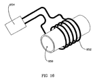
- the invention also provides a chamber for generating a localized and controlled heat source for use in an apparatus for cleaning or maintaining an electrical smoking system, said chamber comprising a geometric form having a longitudinal wall with an integral spiral groove, said wall having an internal and external surface, said groove defining a baffle on said internal surface and an electrical resistance path on the external surface, whereby the interior of the chamber may be heated by the application of electricity to the resistive path.
- the invention further provides a method of cleaning an electrical lighter which heats tobacco or a tobacco containing material to evolve flavors for delivery to a smoker, the cleaning method comprising the steps of: providing a collection surface to collect on the collection surface evolved flavors not delivered to a smoker; and heating the collection surface at a desired time to thermally liberate and thereby clean at least some of the condensate from the collection surface.
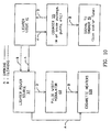
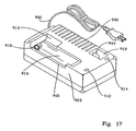
- the invention further provides an apparatus for cleaning and recharging a lighter of an electrical smoking system, comprising: a base unit which is connected to a source of electrical energy; a transformer located within said base unit for converting alternating current to direct current; a receptacle in said base unit for insertion of a lighter containing a battery, said receptacle being in electrical connection with the transformer; a condensate sleeve for trapping condensate formed during electrically powered smoking of tobacco or a tobacco containing flavor medium; a heater in thermal proximity to the condensate sleeve for liberation of condensate therefrom; control circuitry for controlling the recharge and cleaning of the lighter, said control circuitry utilizing transformed direct current energy to charge the battery and thermally liberate condensate from the lighter by activating the heater; and an exhaust port for expelling condensate liberated during cleaning of the lighter.
- Embodiments of the present invention provide methods and apparatuses for using, cleaning and maintaining heaters and electrical lighters useful in smoking systems.
- a preferred embodiment of the present invention provides an indication that cleaning of the heater or lighter is required.
- Preferred embodiments of the present invention provides heating techniques and heating elements for the methods and apparatuses for using, cleaning, and maintaining electrical lighters. Such techniques have the advantage that they effectively clean the heating elements and lighter without damaging sensitive components with excessive heat or effluent.
- Embodiments of the present invention have the advantage of providing methods and apparatuses for cleaning electrical lighters which are relatively simple for the smoker to employ.
- Embodiments of the present invention have the further advantage that they may be combined with and/or contemporaneous with other routine maintenance procedures such as recharging batteries of the electrical lighter.
- the status of a cleaning operation for an electrical lighter is indicated.
- the method and apparatus for cleaning electrical lighters are reusable over the life of an electrical lighter.
- a desired air flow path is provided within an electrical lighter when in use.
- the method and apparatus for cleaning electrical lighters embodying the invention is conveniently powered by the power supply of the electrical lighter.
- the escape of released condensates is reduced by methods including containment, entrapment, and decomposition by heat ultraviolet radiation, and catalysis.
- Preferred embodiments of the present invention may provide a general all purpose tubular micro-scale heater for use in applications requiring controlled heating in a limited space such as the cleaning of a lighter.
- an embodiment of the present invention does not require an additional heating element for the electrical lighter.
- Embodiments of the invention may be simple and straightforward.
- a sleeve e.g., ceramic or metal, surrounds the heater fixture, and a resistive or inductive heating element is in thermal proximity with the sleeve.
- the resistive heating element is either a dedicated element or can be the cigarette heating elements.
- the sleeve serves as a aerosol barrier and condensate accumulator to protect other components.
- the heating element Periodically, e.g., substantially contemporaneously with a battery recharge, the heating element is activated to thermally liberate condensates deposited on the sleeve during smoking.
- the heating of the sleeve also heats, and thereby cleans, other components.
- a cleaning element is optionally inserted into the cigarette receptacle of the electrical lighter or placed at the exit thereof to absorb, attract and/or catalytically break down the thermally liberated condensates. A photo catalytic degradation of the liberated condensates may also be used.
- the sleeve also directs a desired flow path for drawn air within an electrical lighter toward the cigarette and may have an intermediate layer which reflects heat back to the cigarette receptacle; preventing excessive heating of other components.
- the heater assembly herein described finds applications in micro-heater assemblies wherever a controllable pinpoint heat source may be used.
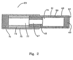
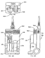
- a smoking system 21 according to the present invention is described in greater detail in U.S. Patent No. 5,388,594 and Application Ser. No. 08/380,718, filed January 30, 1995 issued as US Patent No. 5,666,978 and is generally seen with reference to Figures 1 and 2 of the present application. The present invention is discussed in greater detail with reference to Figures 3-15.
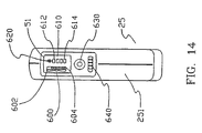
- the smoking system 21 includes a cylindrical cigarette 23 and a reusable, hand-held lighter 25.
- the cigarette 23 is adapted to be inserted in and removed from an orifice 27 at a front end 29 of the lighter 25.
- the smoking system 21 is used in much the same fashion as a conventional cigarette.
- the cigarette 23 is disposed of after one or more puff cycles.
- the lighter 25 is preferably disposed of after a greater number of puff cycles than the cigarette 23.
- the lighter 25 includes a housing 31 and has front and rear portions 33 and 35.
- a power source 37 for supplying energy to heating elements for heating the cigarette 23 is preferably disposed in the rear portion 35 of the lighter 25.
- the rear portion 35 is preferably adapted to be easily opened and closed, such as with screws or with snap-fit components, to facilitate replacement of the power source 37.
- the front portion 33 preferably houses heating elements and circuitry in electrical communication with the power source 37 in the rear portion 35.
- the housing 31 is preferably adapted to fit comfortably in the hand of a smoker and, in a presently preferred embodiment, has overall dimensions of approximately 10.7 cm by 3.8 cm by 1.5 cm.
- the power source 37 is sized to provide sufficient power for heating elements that heat the cigarette 23.
- the power source 37 is preferably replaceable and rechargeable and may include devices such as a capacitor, or more preferably, a battery.
- the power source is a replaceable, rechargeable battery such as four nickel-cadmium battery cells connected in series with a total, non-loaded voltage of approximately 4.8 to 5.6 volts.
- the characteristics required of the power source 37 are, however, selected in view of the characteristics of other components in the smoking system 21, particularly the characteristics of the heating elements.
- U.S. Patent No. 5,144,962 describes several forms of power sources useful in connection with the smoking system of the present invention, such as rechargeable battery sources and quick-discharging capacitor power sources that are charged by batteries, and is hereby incorporated by reference.
- a substantially cylindrical heating fixture 39 for heating the cigarette 23, and, preferably, for holding the cigarette in place relative to the lighter 25, and electrical control circuitry 41 for delivering a predetermined amount of energy from the power source 37 to cigarette heating elements 120 of the heating fixture 39 are preferably disposed in the front 33 of the lighter.
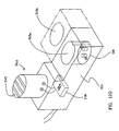
- a generally circular, terminal end hub 110 is fixed, e.g., welded, to be disposed within the interior of cigarette heater fixture 39, e.g., is fixed to spacer 49, as shown in Figure 3.
- the heating fixture 39 includes a plurality of radially spaced heating blades 120 supported to extend from the hub, seen in Figure 3 and described in greater detail below, that are individually energized by the power source 37 under the control of the circuitry 41 to heat a number of, e.g., eight, areas around the periphery of the inserted cigarette 23.
- Eight heating blades 120 are preferred to develop eight puffs as in a conventional cigarette, and eight cigarette heater elements also lend themselves to electrical control with binary devices.
- a desired number of puffs can be generated, e.g., any number between 5-16, and preferably 6-10, or more preferably about 8 per inserted cigarette.
- the heating elements 120 can comprise any suitable heating element for heating tobacco to evolve tobacco flavours.
- the heating system can comprise any of the resistance and induction heating system disclosed in patent No. 5,388,594 and application Serial No. 08/380,718, filed January 30 1995, issued as US patent No. 5,666,718; Serial No. 08/225,120 filed April 8 1994, issued as US patent No. 5,613,505; Serial No. 08/224,848 filed April 8 1994, issued as US patent No. 5,665,262; Serial No. 08/314,463 filed September 28 1994, issued as US patent No. 5,573,692; Serial No. 08/333,470 filed November 2, 1994, issued as US patent No. 5,530,225; Serial No. 08/370,125 filed January 9 1005, issued as US patent No. 5,665,262 and Serial No. 08/426,1265 filed April 20, 1995 and issued as US patent No. 5,591,368.
- the circuitry 41 is preferably energized by a puff sensitive sensor 45, seen in Figure 1, that is sensitive to pressure drops that occur when a smoker draws on the cigarette 23 and in turn activates an appropriate one of the cigarette heater elements or blades 120 as a result of a change in pressure when a smoker draws on the cigarette 23.
- the puff sensitive sensor 45 is preferably disposed in the front 33 of the lighter 25 and communicates with a space inside the cigarette heater fixture 39 and near the cigarette 23 through a passageway extending through a spacer and a base of the cigarette heater fixture and, if desired, a puff sensor tube (not shown).
- a puff sensitive sensor 45 suitable for use in the smoking system 21 is described in U.S. Patent No. 5,060,671.
- An indicator 51 is preferably provided on the exterior of the lighter 25, preferably on the front 33, to indicate the number of puffs remaining on a cigarette 23 inserted in the lighter.
- the indicator 51 preferably includes a seven-segment liquid crystal display.
- the indicator 51 displays the digit "8" for use with an eight-puff cigarette when a light beam emitted by a light sensor 53, seen in Figure 1, is reflected off of the front of a newly inserted cigarette 23 and detected by the light sensor.
- Other embodiments of indicator 51 are described below.
- the light sensor 53 is preferably mounted in an opening in the spacer and the base of the cigarette heater fixture 39.
- the light sensor 53 provides a signal to the circuitry 41 which, in turn, provides a signal to the indicator 51.
- the display of the digit "8" on the indicator 51 reflects that the preferred eight puffs provided on each cigarette 23 are available, i.e., none of the heaters have been activated to heat the new cigarette.
- the indicator displays the digit "0".
- the light sensor 53 does not detect the presence of a cigarette 23 and the indicator 51 is turned off.
- the light sensor 53 is modulated so that it does not constantly emit a light beam and provide an unnecessary drain on the power source 37.
- a presently preferred light sensor 53 suitable for use with the smoking system 21 is a Type OPR5005 Light Sensor, manufactured by OPTEX Technology, Inc., 1215 West Crosby Road, Carrollton, Texas 75006.
- a mechanical switch (not shown) may be provided to detect the presence or absence of a cigarette 23 and a reset button (not shown) may be provided for resetting the circuitry 41 when a new cigarette is inserted in the lighter 25, e.g., to cause the indicator 51 to display the digit "8", etc.
- Power sources, circuitry, puff sensitive sensors, and indicators useful with the smoking system 21 of the present invention are described in US Patent No. 5,060,671 and US Patent Application Serial No's. 07/943,504 issued as US patent No. 5,505,214 and 08/380,718, issued as US patent No. 5,666,978.
- the passageway and the opening 50 in the spacer and the cigarette heater fixture base are preferably air-tight during smoking.
- a presently preferred cigarette 23 for use with the smoking system 21 is described and shown in greater detail in United States Patent No. 5,388,594 and United States Patent Application Serial No's. 08/380,718 filed January 30 1995 and issued as US patent No. 5,666,978; 08/425,166 filed April 20 1995 and issued as US patent No. 5,692,525; and 08/425,837 filed April 10 1995 and issued as US patent No. 5,499,636, although the cigarette or other tobacco format may be in any desired form capable of generating a flavored tobacco response for delivery to a smoker when the cigarette is heated by the cigarette heating elements 120.
- the cigarette heater fixture is disposed in the orifice 27 in the lighter 25.
- the cigarette 23 is inserted, optional back-flow filter 63 first, in the orifice 27 of lighter 25 into a substantially cylindrical space of the cigarette heater fixture 39 defined by a ring-shaped cap 83 having an open end for receiving the cigarette, a cylindrical air channel sleeve 87 (if employed); passageway 48 (if employed); an outer sleeve 84, a heater assembly including the heater blades 120, an electrically conductive pin or common lead 104A, which serves as a common lead for the heater elements of the heater assembly, electrically conductive positive pins or leads 104B, and the spacer.
- the bottom inner surface 81 of the spacer 49 stops the cigarette 23 in a desired position in the cigarette heater fixture 39 such that the heater blades 120 are disposed adjacent the cavity 79 in the cigarette, and in a preferred embodiment are disposed as described in Serial No. 08/425,166, filed April 20, 1995, issued as US patent No. 5,499,636 and Serial No. 08/425,837 filed April 20 1885 and issued as US patent No. 5,499,636.
- Substantially all of the cigarette heater fixture 39 is disposed inside and secured in position by a snug fit with the housing 31 of the front 33 of the lighter 25.
- a forward edge 93 of the cap 83 is preferably disposed at or extending slightly outside the first end 29 of the lighter 25 and preferably includes an internally beveled or rounded portion to facilitate guiding the cigarette 23 into and out of the heater fixture 39.
- the pins 104A and 104B are preferably received in corresponding sockets (not shown), thereby providing support for the cigarette heater fixture 39 in the lighter 25, and conductors or printed circuits lead from the socket to the various electrical elements.
- the pins 104A and 104B can comprise any suitable material and preferably comprise tinned phosphorus bronze.
- the passageway 47 in the spacer 49 and the base 50 communicates with the puff sensitive sensor 45 and the light sensor 53 senses the presence or absence of a cigarette 23 in the lighter 25.
- Each blade 120 forms a resistive heater element in the depicted embodiment. More specifically, a first end of first blade section 116A is electrically connected to the negative terminal of the power supply, and more specifically is an integral extension of hub 110 or is mechanically and electrically connected to hub 110, which in turn is electrically and mechanically connected to negative terminal pin 104A via tack welding or another technique such as brazing or soldering.
- two negative terminal pins 104A are used to provide a balanced support since the negative and positive connections also serve to mechanically support the heaters.
- the hub 110 thus functions as an electrical common for all of the heater blades 120.
- the negative connection for each heater blade 120 can be made individually by, e.g., an appropriate negative contact deposited on an end of the heater opposite the respective positive contact areas 122.
- a respective positive connection for each heater blade 120 is made at connecting end section 122 of the second blade section 116B as discussed in Ser. No. 08/426,165, filed April 20, 1995 issued as US patent No. 5,591,368.
- first leg 116A and second let 116B are serpentine shaped.
- the serpentine shapes of legs 116A and 116B are parallel such that the legs are evenly spaced and gap 1256 is also serpentine-shaped. Such a serpentine shape increases the blade perimeter and aerosol generation and also improves the aerosol entrainment.
- the heater assembly is electrically and mechanically fixed at one end via the welding of pin(s) 104A to hub 110 and of pins 104B to ends 122.
- Pins 104A and 104B are preferably pre-molded into a plastic hub, or otherwise connected thereto, preferably in such a manner so as to minimize air leakage.
- this fixed end is opposite the insertion opening.
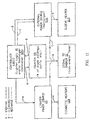
- the electrical control circuitry 41 includes a logic circuit, which is an application specific integrated circuit or ASIC, the puff sensitive sensor 45 for detecting that a smoker is drawing on a cigarette 23, the light sensor 53 for detecting insertion of a cigarette in the lighter 25, the LCD indicator 51, a power source 37, and a timing network, as described in greater detail in U.S. Patent No. 5,388,594 and Ser. No 08/380,718, filed January 30, 1995 issued as US patent No. 5,666,978.
- the logic circuit is any conventional circuit capable of implementing the functions discussed herein.
- a field-programmable gate array e.g., a type ACTEL A1010A FPGA PL44C, available from Actel Corporation, Sunnyvale, California
- a field-programmable gate array can be programmed to perform the digital logic functions with analog functions performed by other components, while an ASIC is required to perform both analog and digital functions in one component.
- control circuitry and logic circuitry similar to the control circuit 41 and logic circuit of the present invention are further disclosed, for example, in U.S. Patent No. 5,060,671 and U.S. Patent Application Serial No. 07/943,504, issued as US patent No. 5,505,214.
- each heater blade 120 is connected to the power source 37 through corresponding field effect transistor (FET) heater switches. Individual ones of the heater switches will turn on under control of the logic circuit through terminals, respectively.
- the logic circuit provides signals for activating and deactivating particular ones of the heater switches to activate and deactivate the corresponding ones of the heaters.
- a cigarette 23 is inserted in the lighter 25, and the presence of the cigarette is detected by the light sensor 53.
- the light sensor 53 sends a signal to the logic circuit.
- the logic circuit ascertains whether the power source 37 is charged or whether there is low voltage. If, after insertion of a cigarette 23 in the lighter 25, the logic circuit detects that the voltage of the power source is low, the indicator 51 blinks and further operation of the lighter will be blocked until the power source is recharged or replaced. Voltage of the power source 37 is also monitored during firing of the heater blades 120 and the firing of the heater blades is interrupted if the voltage drops below a predetermined value.
- the logic circuit sends a signal through to the puff sensor 45 to determine whether a smoker is drawing on the cigarette 23. At the same time, the logic circuit sends a signal to the indicator 51 so that the LCD will display, e.g., the digit "8"or the cigarette icon, reflecting that there are eight puffs available.
- the logic circuit When the logic circuit receives a signal from the puff- sensitive sensor 45 that a sustained pressure drop or air flow has been detected, the logic circuit locks out the light sensor 53 during puffing to conserve power.
- the logic circuit sends a signal to the timer network to activate the constant Joules energy control timer.
- the logic circuit also determines, by a downcount means, which one of the eight heater elements is due to be heated and sends a signal through an appropriate terminal to turn an appropriate one of the FET heater switches ON.
- the appropriate heater blade 120 stays on until the control timer logic determines that a prescribed heater energy has been drawn from the power source.
- the timer network sends a signal to the logic circuit 195 indicating that the timer has stopped running, the particular ON FET heater switch is turned OFF, thereby removing power from the heater element.
- the logic circuit also downcounts and sends a signal to the indicator 51 so that the indicator will display that one less puff is remaining (i.e., "7", after the first puff).
- the logic circuit will turn ON another predetermined one of the FET heater switches, thereby supplying power to another predetermined one of the heater elements.
- the process will be repeated until the indicator 51 displays "0", meaning that there are no more puffs remaining on the cigarette 23.
- the light sensor 53 indicates that a cigarette is not present, and the logic circuit is reset.
- the FET shuts off the heating element to prevent the unwanted generation of excess aerosol.
- disabling features may be provided.
- One type of disabling feature includes timing circuitry (not shown) to prevent successive puffs from occurring too close together, so that the power source 37 has time to recover.
- Another disabling feature includes means for disabling the heater blades 120 if an unauthorized cigarette or other product is inserted in the heater fixture 39.
- the cigarette 23 might be provided with an identifying characteristic that the lighter 25 must recognize before the heater blades 120 are energized.
- the cigarette heating elements 120 are fired to evolve flavors and generate a subsequent puff, condensates on the cigarette heating elements 120 from the previous puff(s) are usually dissipated by this heating. As discussed in greater detail below, the cigarette heating elements 120 can be further cleaned by heat transfer from the heated ceramic sleeve or by being heated individually or en masse with no cigarette present.
- exemplary cleaning apparatuses 190 and associated cleaning methods according to the present invention are shown and described in greater detail.
- the various described devices and methods can be combined in any manner to achieve desired functions.
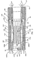
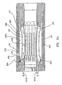
- Cleaning apparatus 190 comprises a cylindrical, preferably swaged, sleeve 200 concentrically surrounding the cigarette heater fixture defined by blades 120, and thus concentrically surrounds inserted cigarette 23.
- cleaning apparatus 190 further comprises an associated heating element 210.
- the heater element 210 transfers heat primarily via conduction to the inner surface 201 of sleeve 200 and indirectly from this heated inner surface 201 primarily via convection and radiation to other component surfaces to thermally liberate condensates deposited thereon.
- sleeve 200 is heated by the cigarette heaters 120, as discussed greater detail below with reference to Figs 9 and 10, or by a heater which is external to the lighter, e.g., located in the recharger unit discussed below, and which is brought into thermal proximity with the sleeve 200 during the combined cleaning and recharging operation discussed below.
- an adequate concentric gap 208 e.g., approximately 0.254mm to approximately 3.048mm (approximately 0.010 to approximately 0.120 inches), e.g., approximately 1.016mm to approximately 2.54 mm (approximately 0.040 to approximately 0.100 inches), preferably separates inner surface 201 of sleeve 200 from the cigarette heater blades 120. If concentric gap 208 is too large, condensates will tend to accumulate undesirably on component surfaces other than the sleeve inner surface 201.
- concentric gap 208 is too small, a smaller air passageway will be defined between sleeve inner surface 201 and the inserted cigarette 23, possibly resulting in an inadequate supply of air being entrained by the smoker and in potentially degraded delivery to the smoker.
- Cylindrical sleeve 200 can define any geometrical shape that comprises a surface for condensing, collecting and/or accumulating at least some of the aerosols not delivered to a smoker.
- inner surface 201 defines a substantially cylindrical inner surface for condensing at least some of the aerosols not delivered to a smoker.
- a cylindrical sleeve is employed for relative ease of fabrication, relative ease of implementation into lighter 25, and to define cylindrical inner surface 201 which surrounds the cylindrical cigarette 23 to form a condensate accumulator.
- Cylindrical sleeve 200 preferably comprises a material which forms a suitable aerosol barrier between the inserted cigarette and other components, in particular relatively outer sleeve 84.
- a ceramic e.g, alumina, e.g., an approximately 94% alumina commercially available from Kyocera America, Co. of San Diego, California or Coors Technical Ceramics Co. of Oak Ridge, Tennessee, or metal, e.g., Haynes® Alloy No.
- heater sleeve 200 should be durable and able to withstand the heating cycle described below for an acceptable period, e.g., the life of the electrical lighter, e.g., approximately 6 to 18 months.
- Heating element 210 and sleeve 200 can be formed from the same material in any of the discussed embodiments if appropriate electrical insulation is provided.
- sleeve 200 is contoured to match the inner bowing of the blades 120, i.e., is substantially parallel therewith, to obtain a relatively quicker and more even application of heat to sleeve 200 if blades 120 are employed as discussed below to heat sleeve 200.
- Sleeve inner surface 201 is a preferred condensate surface relative to these other component surfaces since sleeve inner surface 201 circumferentially surrounds the inserted cigarette 23 to trap evolving aerosol, is dedicated to function as a condensate surface and is suited to a dedicated heating element.
- a heat-reflective intermediate sleeve increases the efficiency of the heating of the surfaces which require cleaning by reducing the heat transferred to the outer sleeve by radiation. This also reduces the rate of increase in temperature of and the peak temperature of the outer sleeve.
- inner sleeve 201 may be heated by the firing of heaters 120 (collectively) to reach a peak temperature.
- Intermediate tube 215A fits between the inner sleeve and outer sleeve 84.
- the intermediate tube may be made of any of a wide variety of reflective high temperature materials which contain heat, and may be selected by one of skill in the art having regard for this disclosure, e.g. an aluminum or gold reflective metallic coating or sheath may be used.
- the heating element 210 in any embodiment should be suitable to be heated to an adequately high temperature to heat, primarily via conduction, the cylindrical sleeve 200, and more particularly sleeve inner surface 201, to preferred operating temperatures of approximately 150°C to approximately 750°C, e.g., approximately 300°C to approximately 600°C, e.g., approximately 400°C to approximately 500°C, e.g., approximately 450°C, as discussed below.
- the heating element 210 is in intimate thermal contact with the cylindrical sleeve 200.
- sleeve 200 is electrically resistive, e.g., a metal as described below, and is directly resistively heated.
- heating element 210 is located within or through sleeve 200 or on inner surface 201, e.g., heating element comprises a resistively heated wire or wires located within or through sleeve 200.
- heating element 210 comprises a resistance heating wire or wires contacting the outer surface 202 of sleeve 200.
- Turns of wire 212 are insulated from one another to prevent short circuits.
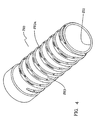
- the resistance heating wire or wires can be wrapped around or alternatively within ceramic or metal sleeve 200 in a spiral fashion and preferably cradled in at least one helical groove 203 formed in the sleeve outer surface 202 and defined by threads 203A, as shown in Figure 4.
- helical groove 203 is a single spiral such that terminal ends of the resistance wire are located at opposite ends of sleeve 200 for connection to an appropriate power source and control logic, as discussed below.
- the sleeve heating element 210 comprises a laminate on a metal sleeve 200. Similar to the cigarette heaters described in Ser. No. 08/224,8, filed April 8, 1994 , issued as US patent No. 5,665,262 and Ser. No. 08/370,125 filed January 9 1995 issued as US patent No. 5,666,262.
- a ceramic layer 310 and a heater layer 210 are deposited on a sleeve 200 having the at least one spiral groove 203 defined by "hills" or spiral thread 203A, as shown in Figure 4. More specifically, the sleeve outer surface 202 is first coated with a ceramic insulator 310 and then resistive heater layer 210 is applied, and preferably thermally sprayed, to ceramic insulator 310 as described below.
- the coated sleeve is ground to remove heater layer 210 and, if desired, ceramic layer 310 from spiral thread 203A so that ceramic layer 310 and heater layer 210 rest in groove 203, as shown in Figure 5.
- a continuous spiral resistive path is accordingly defined wherein each turn of the spiralling heater layer 210 is electrically isolated from adjacent turn(s) via the interposed turns of ground thread 203A which are coated with insulating ceramic layer 310 except for the optionally ground tops or peaks.
- the spiral thread 203A is preferably formed by stamping a sheet of appropriate metal with diagonal depressions or other appropriate patterns and then rolling the stamped sheet to form a sleeve 200 with the desired spiral thread 203A and spiral groove 203 on sleeve outer surface 202.
- This stamping and rolling also forms an inner spiral thread or channel (not shown) and associated inner spiral groove (not shown) located on sleeve inner surface 201.
- the inner spiral thread corresponds to spiral groove 203, and the inner spiral groove corresponds to spiral thread 203A located on sleeve outer surface 202.
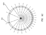
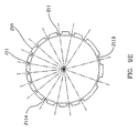
- air is drawn by a smoker into the lighter housing, and specifically is drawn between sleeve inner surface 201 and the outer surface of cigarette 23 as described below, and the defined inner spiral groove on sleeve inner surface 201 serves to direct or channel air drawn by a smoker into the lighter housing around the inserted cigarette 23 in a spiral course, thereby advantageously supplying drawn air to various circumferential locations of the cigarette to result in a more uniform air distribution and a more thorough mixing with the generated flavors in the lighter housing.
- a smooth cylindrical surface surrounding the inserted cigarette 23 results in air, drawn by a smoker into the lighter housing via front holes, being directed in a more streamlined manner and a less thorough mixing in the lighter housing.
- the sheet or formed sleeve is masked prior to the application of the ceramic layer 310 and heater layer 210 to form any desired pattern such as the pattern depicted in Figure 7.
- the defined pattern preferably comprises a continuous resistive path having multiple segments isolated from one another to prevent short circuits.
- an additional electrically insulating coating is applied to the defined pattern of ceramic layer 310 and heater layer 210 to prevent short circuits.
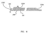
- a preferred sleeve heater 210 and electrical connection is shown in Figures 3 and 6.
- This electrical connection is preferably employed with the spiral configuration described above with reference to Figures 4 and 5 or with any other desired pattern, and is particularly preferred for resistance patterns defined by heater layer 210 having terminal ends at opposite ends of the sleeve outer surface 202.
- an end of the deposited sleeve heater element 210 is in intimate electrical contact with the underlying metal sleeve 200 at contact area 230A and the remainder of sleeve heating element 210 overlies the ceramic insulating layer 310. Plasma coating of the resistive sleeve heating element 210 to the metal sleeve 200 provides a strong contact.
- An electrical common is formed by the electrically conducting metal sleeve 200 which is connected (1) at one end of lighter 25, e.g., the proximal end nearest to the cigarette insertion opening, to the negative terminal end of sleeve heating element 210 via contact area 230A and (2) at the opposite end of lighter 25, e.g., the distal end farthest from the cigarette insertion opening, to the power source via pin 104C and contact area 230C, as shown in FIGs. 3 and 6.
- the positive connection is made via pin 104D to contact area 230B which is also located at the distal end of the lighter opening.
- Sleeve 200 thus functions as a common lead, permitting both contact pins 104C and 104D to be located in a relatively more secure position away from the cigarette insertion opening of lighter 25. Accordingly, a resistive heating circuit for the sleeve 200 is formed which is connected to an appropriate power supply and control logic.
- Sleeve 200 preferably comprises a metal substrate in the form of a cylindrical tube since metal is more flexible for fabrication, has better loading tolerances than a ceramic and, as discussed below, is electrically conductive.
- the metal selected for the substrate is mechanically strong to be fabricated as described below and is a thermally stable metal or alloy.
- a ceramic layer 310 is deposited on the metal sleeve 200 to electrically insulate a subsequently applied sleeve heating element 210 from the metal sleeve except for an exposed negative contact or common 230A.
- the surface roughness of the metal sleeve outer surface 202 is increased to provide better adhesion with the deposited ceramic layer 310.
- the adequately thick outer surface 202 is first roughened by an appropriate technique such as grit blasting and then a bond coat is applied.
- the heating element 310 having a thickness of e.g., approximately 0.00254 mm to 0.254 mm (approximately 0.1 to 10 mils), or approximately 0.0127mm to 0.1524 mm (approximately 0.5-6 mils), and more preferably 0.0254 mm to 0.762 mm (1-3 mils), is deposited next.
- a thickness of e.g., approximately 0.00254 mm to 0.254 mm (approximately 0.1 to 10 mils), or approximately 0.0127mm to 0.1524 mm (approximately 0.5-6 mils), and more preferably 0.0254 mm to 0.762 mm (1-3 mils) is deposited next.
- Significant thermal expansion mismatch between insulator 310 and both the metal sleeve 200 and heater layer 210 possibly leading to delamination should be avoided.
- a material having a high electrical conductivity e.g., of nickel, nickel alloys, copper, or aluminum, is sprayed on heater element 210 and the sleeve substrate to form respective contact areas 230B and 230C and then leads, e.g., pins 104D and 104C, are affixed, e.g., by welding, brazing or soldering, as discussed.
- the material can be integrally formed to leads or soldered, and preferably silver soldered, thereto in lieu of the connecting pins.
- the high conductive material makes the underlying area less resistive and permits the leads to be more easily added as discussed.
- the metal sleeve 200 can be made from an alloy in the form of a sheet, rod or bar, e.g., by drawing.
- appropriate metals include NiCr alloys, Haynes® 214 alloy ( Haynes® Alloy No. 214, a nickel-based alloy containing 16.0 percent chromium, 3.0 percent iron 4.5 percent aluminum, traces of yttrium and the remainder (approximately 75 percent) being nickel, commercially available from Haynes International of Kokomo, Indiana) and Inconel 625 alloy sheet.
- the metal sleeve is constructed from a nickel aluminide (Ni 3 Al) alloy, another alloy of nickel and iron or an iron aluminide alloy (Fe 3 Al) could be employed, as discussed above.
- the ceramic layer 310 preferably has a relatively high dielectric constant.
- Any appropriate electrical insulator can be employed such as alumina, zirconia, mullite, cordierite, spinel, forsterite, combinations thereof, etc.
- zirconia or another ceramic is employed which is thermally stable and having a thermal coefficient of expansion which closely matches that of the underlying metal sleeve to avoid differences in expansion and contraction rates during heating and cooling, thereby avoiding cracks and/or delaminations during operation.
- the ceramic layer remains physically and chemically stable as the heating element 210 is heated.
- the tube is spun a number of times during coating to apply a proper coating.
- the bond coat is a thin, e.g., 0.00254 mm to 0.127 mm (0.1 to 5 mil) and preferably 0.0127 mm to 0.0254 mm (0.5 to 1.0 mil) layer of a metallic coating such as FeCrAlY, NiCrAlY, NiCr, NiAl or Ni 3 Al and provides good bond interface between the roughened metal sleeve outer surface 202 and the subsequent applied ceramic layer 310.
- a metallic coating such as FeCrAlY, NiCrAlY, NiCr, NiAl or Ni 3 Al
- deposition techniques are alternatively employed in addition to thermal spraying, and more particularly plasma spraying.
- a chemical type of bonding is preferred for bonding strength.
- This chemical bonding is achieved by heating the ceramic layer, or ceramic precursor, with the metal outer surface 202 at a relatively high temperature.
- the metal sleeve 200 is heated at a high temperature to form an oxide layer on the surface which performs similarly to the ceramic layer.
- any appropriate metal, compound, or alloy, with or without intermetallic/ceramic additives, can be employed for heating element 210, in a power form if required by the deposition technique. More specifically, an approximately 0.00254 mm to 0.127 mm (0.1 to 5 mil) layer of an electrically resistive material such as the above discussed materials, e.g., NiCr, Ni 3 Al, NiAl, Fe 3 Al or FeCrAlY, is deposited by any known thermal spraying technique such as plasma coating or HVOF (High Velocity Oxy Fuel).
- an electrically resistive material such as the above discussed materials, e.g., NiCr, Ni 3 Al, NiAl, Fe 3 Al or FeCrAlY
- plasma coating or HVOF High Velocity Oxy Fuel
- the resistivity of the resistive material may be adjusted with the addition of suitable ceramics or by adjusting the oxidation level of the metal during plasma or HVOF spraying.
- Thin film techniques e.g, CVD or PVC, can be used if the surface roughness of the ceramic layer 310, comprised of relatively large ceramic particles compared to the heater material, is smoothed by, e.g., diamond grinding to a surface roughness between 3.43 microns to 4.06 microns (135 to 160 micro-inches Ra), with an average of 3.68 microns (145 micro-inches Ra).
- CVD chemical vapor deposition
- heating element 210 can be platinum formed onto ceramic layer 310 or onto ceramic sleeve 200 as described in commonly assigned, copending application Serial No. 08/314,463 filed September 28 1994 and issued as US patent No. 5,573,692.
- thermal spraying is preferred to-provide resistive heater layer 210. It can be sprayed using a variety of thermal spraying techniques. A pre-alloyed Ni 3 Al, a mechanically alloyed Ni 3 Al, or a powder of Ni and Al in the proper ratio can be used. A pre-heating step is needed if mechanically alloyed Ni 3 Al or if Ni and Al powders are used for spraying applications.
- Temperature and time for pre-heating will depend on the thermal spray gun parameters and can be adjusted to fall in the range of 600°C to 1000°C. Particle sizes and size distributions are important to form Ni 3 Al if a pre-alloyed Ni 3 Al is not used.
- a composition of NiAl can be used.
- B and Si are the principal additions to the alloy for heater layer 210.
- B is thought to enhance grain boundary strength and is most effective when the Ni 3 Al is nickel rich, e.g., Al ⁇ 24 atomic percent.
- Si is not added to the Ni 3 Al alloys in large quantities since addition of Si beyond a maximum of 3 weight percent will form silicides of nickel and upon oxidation will lead to SiO x .
- the addition of Mo improves strength at low and high temperatures. Zirconium assists in improving oxide spalling resistance during thermal cycling. Also, Hf can be added to improved high temperature strength.
- a preferred Ni 3 Al alloy for use as the sleeve 200 and resistive heater 210 is designated IC-50 and is reported to comprise 77.92 at. % Ni, 21.73 at% AI;. 0.34 at% Zr and 0.01 at% B in "Processing of Intermetallic Aluminides", V. Sikka, Intermetallic Metallurgy and Processing Intermetallic Compounds, ed. Stoloff et al., Van Nostrand Reinhold, N.Y., 1994, Table 4.
- Various elements can be added to the aluminide. Possible additions include Nb, Cu, Ta, Zr, Ti, Si, Mo and Ni.
- the heater material for heating element 210 can be Haynes® 214 alloy.
- Haynes® Alloy No. 214 is a nickel-based alloy containing 16.0 percent chromium, 3.0 percent iron 4.5 percent aluminum, traces of yttrium and the remainder (approximately 75 percent) being nickel, commercially available from Haynes International of Kokomo, Indiana).
- Inconel 702 alloy, NiCrAIY alloy, FeCrAlY, Nichrome® brand alloys 54-80% nickel, 10-20% chromium, 7-27% iron, 0-11% copper, 0-5% manganese, 0.3-4.6% silicon, and sometimes 1% molybdenum, and 0.25% titanium may also be used.
- Nichrome I is stated to contain, inter alia, 60% nickel, 25% iron, 11% chromium, and 2% manganese; Nichrome II, 75% nickel,; and Nichrome III, a heat-resisting alloy 85% nickel and 15% chromium, as described in commonly assigned US Patent No. 5,388,594, or materials having similar properties.
- the heating element 210 is made from a heat-resistant alloy that exhibits a combination of high mechanical strength and resistance to surface oxidation, corrosion and degradation at high temperatures.
- the heating element 210 is made from a material that exhibits high strength and surface stability at temperatures up to commonly referred to as super-alloys and are generally based on nickel, iron, or cobalt.
- alloys of primarily iron or nickel with aluminum and yttrium are suitable.
- the alloy of the heating element 210 includes aluminum to further improve the performance of the heating element, e.g., by providing oxidation resistance.
- Preferred materials include iron and nickel aluminides and most preferably the alloys disclosed in commonly assigned, copending US patent applications Serial No. 08/365,952 filed December 29 1994 and issued as US patent No 5,595,706, entitled “Aluminium Containing Iron-Base Aloys Useful as Electrical Resistance Heating Elements” and Serial No. 08/426,006 filed April 20 1995, and issued as US patent No. 5,620,651 entitled “Iron Aluminide Alloys Useful as Electrical Resistance Heating Elements” (Attorney Docket No. PM 1769).
- any alloy is required, preferably an argon gas cover is employed.
- Electrical leads can be brazed to the resistive heater 210 or sleeve 200 as discussed using a YAG laser or CO 2 laser. Brazing can be accomplished with Ag-Cu or Ni-Cu brazing alloys. Brazing is a preferred method over soldering and welding for these purposes since the thickness of resistor is less than 5 mil. (.005") or 0.125 mm. A flux can be used to wet the surface and clean the oxides.
- Several such brazing alloys are available from Lucas-Milhaput of Wisconsin and from Indium Corporation of America. Ag-Cu alloys have optimum solidus and liquidus temperatures for laser brazing of a heater without penetrating through the layers since the total thickness of the heater 210 and insulator 310 is 0.254 mm to 0.381 mm (10 to 15 mils).
- the present invention provides a multi-layer heater with Ni 3 Al as a substrate and as a heater separated by an insulator, zirconia.
- the concept is generic and can be applied in different thicknesses to various geometries.
- Ni 3 Al readily forms an adherent alumina layer on the surface. This alumina layer will prevent further oxidation and will eliminate spalling of oxides, thereby enhancing cycle life time of the material.
- a cylindrical tube of the selected metal having an appropriate length and a wall thickness of approximately 0.0254 to 0.254 mm (1-10 mils), and preferably 0.0762 mm to 0.127 mm (305 mils) is formed in the desired geometrical shape.
- the tube is formed by, e.g., stamping or extrusion; (2) the ceramic and heater layers are deposited; and (3) the heater and electrical leads are bonded.
- a thin tubing having e.g., approximately 0.0762 mm to 0.127 mm (3 to 5 mil) thick walls is provided with an adequate initial diameter.
- the tube is cut into desired lengths to subsequently form substrates.
- conventional swaging technicues are performed to form the desired geometry and size of the substrate and tube(s).
- Subsequent steps are performed as described to form the sleeves 200.
- the fabrication of steps defined herein may be performed in any desired order to achieve manufacturing speeds, materials savings, etc.
- the heater materials and other metallic components are also chosen based on their oxidation resistance and general lack of reactivities to ensure that they do not oxidize or otherwise react with the cigarette 23 at any temperature likely to be encountered. If desired, the heating element 210 and other metallic components are encapsulated in an inert heat-conducting material such as a suitable ceramic material to further avoid oxidation and reaction.
- heating element 210 is arranged in a resistive heating pattern 220 to form a resistance heating circuit powered by an appropriate source of electrical energy.
- a particularly preferred heating element 210 is shown in Figure 7 comprising a resistive pattern formed on the outer surface 202 of cylindrical sleeve 200, e.g., a wave pattern having a relatively elongated amplitude in the longitudinal direction of the underlying sleeve 200 as shown.
- the resistive pattern can comprise tungsten and is applied to sleeve 200, e.g., alumina as discussed, via any conventional technique, e.g. as performed by Ceramx Corporation of Laurens, South Carolina.
- the resistive pattern is printed on a plastic tape, transferred to ceramic green tape and then from the tape to the ceramic sleeve via firing.
- any appropriate pattern can be employed to achieve desired operating temperatures as discussed herein. As shown in Figure 7, the negative and positive terminal ends of the resistive pattern are located near the same end of sleeve 200 for connection with negative and positive pins 104C and 104D.
- the resistance pattern e.g., platinum
- the resistance pattern is formed in a desired pattern onto the ceramic sleeve 200 as shown in commonly assigned, copending application Serial No. 08/333,470 filed November 2, 1994, issued as US patent No. 5,530,225
- the resistance pattern is formed in a desired pattern onto the ceramic sleeve 200 as shown on a flat substrate in commonly assigned U.S. Patent No. 5,408,574, issued April 18, 1995, which is a continuation-in-part of commonly assigned U.S. Patent No. 5,224,498, issued July 6, 1993, which is a continuation-in-part of commonly assigned U.S. Patent No. 5,093,894 issued March 3, 1992, which are hereby incorporated by reference in their entireties.
- a continuous wire 212 is cradled in helical groove 203 defined by "hills" of spiral thread 230A shown in Figure 4.
- continuous wire 212 comprises a first leg 212A and a second leg 212B, the latter of which is striped for clarity of depiction, alternatingly disposed in a respective helical groove 203 of a double-threaded sleeve 200 and separated by such that terminal ends of wire 212 are located at the same end of sleeve 200 for convenient connection to an appropriate power source and control logic.
- a connecting segment 212C connects first leg 212A to second leg 212B, specifically by: (1) passing through and into sleeve 200 via a first aperture preferably located at an end, e.g., the distal end, of sleeve 200 opposite pins 104C and 104D, (2) travelling along inner surface 201 for a short interval, and (3) passing through and out of sleeve 200 via a second aperture located in the adjacent spiral turn to the first aperture.
- double-threaded it is meant that sleeve 200 has two parallel helical grooves. Such a configuration permits electrical connections at terminal ends located at the same sleeve end.
- contact areas 230C and 230B permit negative and positive connections to the source of electrical energy. More specifically, a positive connection is made at a first terminal of resistive heating element 210 and a negative connection is made at a second terminal of resistive heating element 210.
- a sleeve negative or common pin 104C and sleeve positive pin 104D are respectively located in base 50, received by additional sockets (not shown) connected ultimately to control circuitry and to the desired sleeve power source, and respectively make the negative connection and positive connection of sleeve heating element 210 to complete the connection to the desired sleeve power source.
- both of the connections of the sleeve heating element 210 with pins 104C and 104D are made at base 50, i.e., the end of fixture 39 opposite the cigarette insertion opening to avoid interference by and with the cigarette.
- base 50 i.e., the end of fixture 39 opposite the cigarette insertion opening to avoid interference by and with the cigarette.
- negative, common and positive designations can be alternated in the present invention as depicted with respect to sleeve heating element 210 since only one heater is employed.
- multiple heating elements 210 can be employed to heat sleeve 200, and a common can be employed for the multiple heating elements 210.
- the heating of the sleeve may take place by use of an inductive heating apparatus as seen in Figure 16.
- Sleeve 850 is formed of an appropriate susceptor material which is capable of sustaining and enduring temperatures high enough to vaporize accumulated deposits by thermal liberation.
- the induction coil 852 is in the lighter housing and is powered by driving circuit 854.
- the driving circuit should generate a sufficient amount of power (in the vicinity of approximately 10 watts) to sufficiently heat the susceptor tube.
- the tube may be made of any suitable susceptor material subject to the requirements of the heater, and the power and frequency requirements chosen accordingly. It has been determined that for, e.g., a stainless steel tube of radius 4.26 x 10 -3 m, thickness 7.62 x 10 -5 m, length 1.4 x 10 -2 m, a frequency of 500 KHz is optimal, with 700 KHz being the maximum useful frequency. A temperature rise of 425°C from ambient is observed within 5 seconds of the circuit energization.
- the number of turns around the tube is variable depending on the power dissipation and size of the tube chosen, but for the exemplary stainless steel tube, 50 turns gives a sufficient magnetic flux density.
- the coil may be placed adjacent to the sleeve (placed within the lighter housing), or in a spaced relation to the sleeve (e.g. in the cleaner apparatus housing). In the instance where the inductive coil is placed within the lighter, less power is required, but the coil and associated circuitry is then mounted in the lighter and increases the carry-around weight of the apparatus. In the instance where the inductive coil is place in the cleaner apparatus housing, the power requirement for inductive heating is dramatically increased.
- the desired sleeve power source can be batteries or other power source 37 of the lighter 25. More preferably, heating element 210 is powered by an external power source such as a recharger unit 500, as described below, which is also suitable for recharging the rechargeable batteries of lighter 25 and connected, e.g., to a conventional wall outlet or other source of AC or DC current capable of providing approximately 25 watts to approximately 50 watts for the cleaning process.
- an external power source such as a recharger unit 500, as described below, which is also suitable for recharging the rechargeable batteries of lighter 25 and connected, e.g., to a conventional wall outlet or other source of AC or DC current capable of providing approximately 25 watts to approximately 50 watts for the cleaning process.
- the batteries may require recharging after approximately 160 to 800 heater firings corresponding to approximately 160 to 800 puffs, i.e., equivalent to approximately 20 to 100 cigarettes (assuming 8 firings and puffs per cigarette) or 1 to 5 packs (assuming 20 cigarettes per pack).
- recharging would take place during an adequately long period of non-use, e.g., at the end of a day or a set number of days, with cleaning preferably occurring at each recharging or at some set multiple thereof.
- condensates accumulate on the inner surface 201 of sleeve 200, the cigarette heating elements 120 and other lighter components with each generated puff.
- a counter 55 is provided within lighter 25 to count the desired events which could be used to indicate that cleaning is required, e.g., after a certain number of recharges or every recharge, or after a certain number of cigarettes, puffs or discrete heatings of a cigarette heater, etc. Note that if recharging occurs after a predetermined number of cigarettes, recharge(s), puffs or discrete heatings of a cigarette heater, etc., then counting and storing events for both recharging and cleaning are efficiently combined.
- an icon on display 51 can indicate the need for cleaning in response to a signal from counter 55 upon a predetermined number of event(s) or at some established number of event(s) prior to the predetermined number. In the latter case, the icon is displayed at some determined interval prior to the cleaning trigger event to alert the smoker of the upcoming required cleaning, e.g., so that he or she can initiate the cleaning cycle prior to an intended period of extended use or plan to use another lighter while the current lighter is being cleaned.
- another alert signal can be communicated to the smoker, e.g., any conventional audio signal such as a beep or other generated tone before, with or after the time of the icon display.
- control logic can "lock out” a smoker if cleaning is not performed, e.g., by the control logic 41 implementing a "stop" mode which prevents firing of the heaters once the counter 55 sends a signal indicative of required cleaning to the control logic 41 of the lighter, e.g., after a predetermined number of smoked cigarettes and/or coincident with required battery recharging.
- either lighter control circuitry 41 and/or recharger logic controller 520 implements a "go" mode to allow use to resume.
- All of the foregoing control information is preferably stored in conventional non-volatile memory to permit the cleaning history and associated counting and signalling to be preserved if power source 37 is depleted.
- the cleaning cycle is preferably initiated at the determined time by the smoker entering a code and/or activating a push-button, switch, etc. or interfacing the lighter with an external unit such as a recharger unit 500 as described below.
- the lighter 25, with cigarette removed is inserted or otherwise engaged with a suitable recharger 500 as described below containing a power source and/or connected to a conventional electrical source such as an outlet, whereby electrical power is transmitted from the recharger 500 to the lighter power source 37, e.g., rechargeable batteries, and control signals are transmitted from the recharger to the lighter control circuitry 41.
- the dedicated sleeve heating element(s) 210 is powered via lighter power source 37, e.g, batteries, or, more preferably, by the recharger 500 at approximately 25-50 watts.
- heating element(s) 210 is resistively heated by the supplied electrical power
- the sleeve inner surface 201 is heated, primarily via conduction, an appropriate amount to thermally liberate the condensates thereon.
- the sleeve 200, and especially the inner surface 201 thereof which accumulates condensates, is heated substantially uniformly to a desired minimum temperature to clean the lighter components effectively, e.g, to preferred operating temperatures of approximately 150°C to approximately 750°C, e.g., approximately 300°C to approximately 600°C, e.g., approximately 400°C to approximately 500°C, e.g., approximately 450°C.
- the desired minimum temperature is reached from room temperature in, e.g., approximately 10 to approximately 90 seconds and held for, e.g., up to approximately 60 seconds.
- the cleaning cycle is controlled by appropriate logic preferably embodied in either lighter control circuitry 41 and/or control circuitry located in the recharger 500.
- this heating of sleeve 200 transfers heat, primarily via conduction, convection and radiation, to other internal components of the lighter such as air channel sleeve 87 (if employed); passageway 48 (if employed); outer sleeve 84; heater assembly 100 including the heater blades 120; common pin or lead 104A; positive pins or leads 104B; the spacer 49, especially the bottom inner surface 81 of the spacer; base 50; and the passageway 47 in the spacer and the base 50 communicating with the puff sensitive sensor 45 and thereby thermally liberate undesired condensate deposits from these internal components.
- air channel sleeve 87 if employed
- passageway 48 if employed
- outer sleeve 84 heater assembly 100 including the heater blades 120; common pin or lead 104A; positive pins or leads 104B; the spacer 49, especially the bottom inner surface 81 of the spacer; base 50; and the passageway 47 in the spacer and the base 50 communicating with the puff sensitive sensor 45 and thereby thermally
- those component surfaces are heated to approximately 100°C to approximately 400°C for, e.g., approximately 10 to 90 seconds.
- the heating elements 210 are designed and arranged to heat the sleeve 200, and especially the inner surface 201 thereof, substantially uniformly to a desired minimum temperature to clean the sleeve and lighter components effectively, e.g, to preferred operating temperatures of approximately 150°C to approximately 750°C, e.g., approximately 300°C to approximately 600°C, e.g., approximately 400°C to approximately 500°C e.g., approximately 450°C for, e.g., approximately 10 to approximately 120 seconds, or from approximately 30 to approximately 90 seconds, or approximately 20 to approximately 60 seconds.
- Certain areas e.g., portions of sleeve inner surface 201 underlying electrical contact areas 230, could be relatively cooler, e.g., due to heat sink properties of the electrical connecting elements. These cooler regions could be between, e.g., approximately 15°C to approximately 50°C cooler than the remainder of the sleeve 200.
- the resistivity of the heating elements 210 and/or the power supplied is selected such that these relatively cooler regions reach the desired minimum cleaning temperature and the other regions are heated to a correspondingly higher, though still suitable, cleaning temperature, e.g., to preferred increased operating temperatures of approximately 15°C to approximately 50°C higher than the approximately 150°C to approximately 750°C and other ranges in the foregoing examples. It is noted that an alumina or metal sleeve 200 is selected to exhibit substantially uniform thermal conductivity.
- Relatively lower temperature volatiles of the condensate are initially vaporized as the water present vaporizes at 100°C and are released in gas and/or aerosol states.
- relatively higher temperature condensates undergo revolatilization or pyrolysis and are released.
- any residual condensates are oxidized. It is believed that one or more of these processes is responsible for the observed cleaning of the sleeve 200 and other condensation surfaces.
- the thermally liberated condensates are generally referred to as volatiles.
- the cigarette heaters 120 themselves are used to heat inner surface 201 of sleeve 200 during the cleaning cycle in addition to heating the inserted cigarette 23 during normal smoking, thus obviating the need for a specific dedicated heating element 210 for the condensate sleeve 200, as shown in Figure 9A.
- the cleaning cycle is preferably initiated at the determined time by the smoker in response to an indication that cleaning is required.
- Cigarette heaters 120 are pulsed, preferably in a rapid sequential pattern, at the determined cleaning time with no cigarette 23 present in the heater assembly 39 to heat sleeve inner surface 201 substantially uniformly to the desired temperature, primarily via radiation and conduction.
- desired cleaning temperature range approximately 150°C to approximately 750°C, approximately 300°C to approximately 600°C, e.g., approximately 400°C to approximately 500°C, for sleeve inner surface 201 for, e.g., approximately 30 to approximately 60 seconds
- the individual heater blades 120 are heated to approximately 600°C to approximately 800°C and held for approximately 20 to approximately 60 seconds.
- the required power would dissipate the capacity of most conventional batteries. Accordingly, energy would be required to be supplied from an external source, e.g., the below discussed recharger unit 500 which in one embodiment is connected to a conventional electrical outlet.
- the blades 120 are subjected to sustained heating which could be potentially damaging.
- each heater blade 120 is fired approximately 20 to approximately 200 times per second, e.g., approximately 40 to 60 times per second, e.g., approximately 50 or approximately 100 times per second, to achieve the desired sleeve heating.
- Preferred pulse widths are determined by considerations including the available power supply, e.g., an external power source; desired ramp-up and hold times for the heating of blades 120 during cleaning; and material properties of blades 120, including the rapid cyclic heatings during cleaning and the operating temperatures during cleaning. If desired, the determined pulse width for each heater could be shortened to prevent excessive heating of the sleeve 200.
- the heater pulsings of all of the blades 120 can be in any desired order.
- pulse width modulator 60 is located in the recharger unit 500.
- the power for heating the cigarette blades 120 is supplied by the recharger unit.
- the energy supplied to pulse width modulator 60 is appropriately shaped to use energy from both the recharger unit and from the lighter power source 37 to condition the battery.
- an additional sleeve 215 is provided between outer sleeve 84 and sleeve outer surface 202 and has a heat reflective inner surface 215A surrounding and facing sleeve outer surface 202.
- Sleeve 215 is preferably separated from sleeve 200 by a gap and is either is contact with or separated from outer sleeve 84.
- sleeve outer surface 202 is also heated. Heat radiates from sleeve outer surface 202 and is reflected back toward sleeve outer surface 202 by the heat reflective inner surface 215A of sleeve 215 both to reduce the amount of heat transferred to outer sleeve 84 and/or to the exterior walls of lighter 25 and to increase the heat transfer efficiency to the sleeve outer surface 202 and ultimately to sleeve inner surface 201 to clean inner surface 201.
- Sleeve 215 also functions as a heat sink to absorb non-reflected radiative heat to further reduce the amount of heat transferred to outer sleeve 84 and/or to the exterior walls of lighter 25. Additional sleeve 215 having heat reflective inner surface 215A surrounding and facing sleeve outer surface 202 can be provided between outer sleeve 84 and condensate sleeve outer surface 202 in any of the disclosed embodiments of the present invention.
- a cyclic cleaning control scheme for the heater blades is employed wherein the blades are heated for a period, allowed to cool, heated again, cooled again, etc. to further reduce the possibility of overheating heat sensitive components of the lighter 25.
- the heater blades 120 can be pulsed, preferably pulse width modulated as discussed, for, e.g., a period of approximately 10 to approximately 30 seconds in an "on" mode allowed to cool for, e.g., a period of approximately 200 to approximately 300 seconds in an "off” mode. This procedure is cycled for an adequate time to clean the components, e.g., for 1 to 20 of these "on-off" cycles.
- control logic for controlling the pulsings of the cigarette heaters 120 via the appropriate power source is contained either in the control circuitry 41 of lighter 25 or in control circuitry of an external component, e.g., the recharger unit.
- the tobacco containing cigarette 23 is preferably removed from the lighter by the smoker prior to initiating the cleaning cycle, and thus the heating element(s) employed in cleaning does not heat the tobacco to evolve flavors during the cleaning cycle.
- the control circuitry 41 of lighter 25 and/or recharger logic controller 520 will "lock out” or prevent a cleaning cycle by implementing a "stop” mode which prevents firing of the heating element 210 if the light sensor 53 indicates that a cigarette 23 is present in the lighter 25.
- control circuitry 41 of lighter 25 and/or recharger logic controller 520 will "lock out” or prevent a cleaning cycle by implementing a "stop” mode which prevents firing of the cigarette heating elements 120 if the light sensor 53 sends a signal indicating that a cigarette 23 is present in the lighter and if, as discussed above, the counter 55 has sent a signal indicating that cleaning as required.
- Either lighter control circuitry 41 and/or recharger logic controller 520 implements a "go" mode to allow cleaning, including actuation of heating element 210 or the heater blades 120, if the light sensor 53 indicates that a cigarette is not present.
- a defined inner spiral groove on sleeve inner surface 201 serves to further direct or channel air drawn by a smoker into the lighter housing around the inserted cigarette 23 in a spiral course, thereby advantageously supplying drawn air to various circumferential locations of the cigarette to result in a more uniform distribution of air and a more thorough mixing in the lighter housing.
- a smooth cylindrical surface surrounding the inserted cigarette 23 results in air, drawn by a smoker into the lighter housing, being directed in a more streamlined manner and a less thorough mixing in the lighter housing.
- the air is then directed around a distal end of sleeve 200, along gap 208 by the sleeve inner surface 201 and towards the inserted cigarette 23.
- Unimpeded flow from the sleeve outer surface 202 or, if employed, the outer surface of sleeve 215 will tend to concentrate the pressure drop at a portion of gap 208 underlying passageway 48 with every puff, thereby causing potentially inconsistent subjective attributes for each puff generated by a respective circumferentially arranged heater blade 120. Accordingly, it may be desirable to establish a more uniform flow within gap 208 about cigarette 23 to provide relatively consistent subjective attributes for each puff generated by a respective one of the circumferentially arranged heater blades 120.
- annular portion or shoulder 209 is located on or near a distal end of sleeve outer surface 202 between sleeve 200 and outer sleeve 84.
- Annular shoulder 209 is configured to redistribute the air flow to establish a substantially uniform pressure drop.
- annular shoulder 209 can comprise a porous plug of an appropriate material having the requisite porosity distribution to establish a uniform pressure drop, e.g., a distribution of drawn air.
- annular shoulder 209 defines a substantially airtight seal between sleeve 200 and outer sleeve 84 except for a plurality of circumferential grooves or slots 211 therethrough to redistribute the air flow and establish a substantially uniform pressure drop.
- grooves 211 are uniformly sized, e.g., approximately 0.381 mm (.015 in.) wide, and uniformly distributed at, e.g., twenty four intervals.
- grooves 211 are uniformly sized, e.g., approximately 0.381 mm (.015 in.) wide, and nonuniformly distributed such that grooves 211 are more spread apart overlying the portion of gap 208 underlying passageway 48 where the pressure drop ends to concentrate, i.e., more uniformly sized grooves 211 are present at other portions of the gap to provide more air thereto to equalize airflow to gap 208.
- grooves 211 are uniformly sized, e.g., approximately 0.381 mm (.015 in.) wide, and nonuniformly distributed, although the distribution shown in Figure 9D is more uniform than the distribution shown in Figure 9C.
- the defined grooves are nonumiformly sized and nonuniformly distributed. More specifically, in Figure 9E the grooves 211 are, e.g., approximately 0.381 mm (.015 in.) wide and are located at the portion of gap 201 underlying passageway 48 where the pressure drop tends to concentrate.
- grooves or slots 211A are located circumferentially adjacent to grooves 211, and still larger e.g., approximately 1.143 mm (.045 in.) wide, grooves or slots 211B are located circumferentially adjacent to grooves 211A.
- a defined inner spiral groove on sleeve inner surface 201 serves to further direct or channel air drawn by a smoker into the lighter housing around the inserted cigarette 23 in a spiral course, thereby advantageously supplying drawn air to various circumferential locations of the cigarette to result in a more uniform distribution of air and a more thorough mixing in the lighter housing.
- a smooth cylindrical surface surrounding the inserted cigarette 23 results in air drawn by a smoker into the lighter housing being directed in a more streamlined manner and a less thorough mixing in the lighter housing.
- the puff sensitive sensor 45 is located within passageway 48.
- a recharger unit 500 comprising a battery recharger power supply 510 connectable to an external power source such as a wall outlet; a recharger logic controller 520 schematically shown in Figures 11; and a sleeve heater power supply 530.
- Battery pack 37a, 37b containing rechargeable batteries 37 is detachable from the housing of lighter 25 in a conventional manner, e.g., via known male and female socket type electrical and mechanical contacts.
- one depleted battery pack 37b is situated in battery pack receptacle 515 to interface with any appropriate battery recharger power supply 510.
- Another charged battery pack 37a is connected to lighter 25 to provide a portable power supply when the lighter is not interfacing with recharger unit 500.
- the two battery packs 37a, 37b are then conveniently switched upon depletion of one battery pack to provide a charged battery pack for the lighter and to begin recharging of the depleted battery pack.
- the lighter 25 is situated in heater power supply receptacle 535 to interface with recharger power supply 530.
- This electrical energy supply is controlled by control circuitry 41 of lighter 25 and/or recharger logic controller 520 of recharger unit 500.
- the cleaning cycle is initiated upon positioning lighter 25 within receptacle 535 and is conducted as described. See the schematic of Figure 11.
- two battery pack receptacles 515a and 515b are employed with a single recharger unit 500.
- Recharger 510 is preferably connected to one battery pack receptacle 515a, and the other battery pack receptacle 515b functions as a storage port.
- This battery pack receptacle 515b functioning as a storage port does not require electrical connections to also function as a recharging port, but can optionally have such connections to permit recharging of a second battery pack 37b.
- a cleaning pedestal 540 extends from an upper surface of recharger unit 500 and is sized such that, upon proper positioning, pedestal 540 rests within lighter 25 in lieu of the recently removed, depleted battery pack.
- Pedestal 540 is connected to recharger power supply 530 and is provided with an orientation slot 545 to couple with a corresponding surface (not shown) of lighter 25 to ensure appropriate orientation for electrical connections.
- Base unit 920 is formed with spare charging port 900 which has flute 904 for ensuring correct battery orientation.
- Power cord 902 supplies AC power to the system and a transformer (not shown) converts it to DC power of appropriate voltage and amperage.
- Indicator 914 shows the charging mode of charging port 900 (i.e. its operational status - charging, charged, standby). Charging is controlled by power management circuitry.
- Lighter port 916 receives the hand held lighter. Cavity 910 allows for easy grasping of the inserted lighter for ease of removal. Indicator 912 indicates the status of the lighter, e.g. charging, cleaning, cleaned, and charged. Aperture 918 is fluidly connected with a fan (not shown) which exhausts the volatilized substances from the lighter and exhausts them through vents 906.
- the volatilized condensates may be broken down by catalytic degradation. Downstream from the aperture and before the exhaust vents a supported platinum catalyst may be mounted in the charging/cleaning unit. Electromagnetic induction or resistive heating is used to heat a support material coated with platinum. If the heater is inductive, an appropriate inductor (e.g. stainless steel) is used. The heater is heated to a temperature of from 200-800°C, most preferably about 300°C to degrade the liberated condensates.
- an appropriate inductor e.g. stainless steel
- the fan intakes sufficient oxygen to decompose the condensate without a significant visible or odorifous product.
- a heat exchanger may be utilized to cool the exhaust gases.
- a charged battery pack is moved from the battery charger receptacle 515a to the storage port 515b.
- the depleted battery pack is then removed from lighter 25 and placed in the recently vacated battery charger receptacle 515a for charging.
- a depleted battery pack is removed from lighter 25 by unlocking an appropriate coupler via switch 640.
- Lighter 25 is coupled to pedestal 540 and thus to power supply 530 via appropriate electrical contacts, e.g., via known male and female socket type electrical and mechanical contacts, to accomplish cleaning as described.
- appropriate electrical contacts e.g., via known male and female socket type electrical and mechanical contacts, to accomplish cleaning as described.
- the lighter 25 is removed from pedestal 540, the charged battery pack is removed from the storage port 515b and coupled to the lighter 25.
- the lighter 25 Upon timely conclusion of cleaning, e.g., a few minutes, the lighter 25 is decoupled from recharger unit 500 by the smoker and is immediately ready to be smoked with the charged battery pack, while the relatively longer recharge cycle, e.g, several hours or overnight, is performed for the other depleted battery pack remaining in recharge port 515a.
- Such a contemporaneous full cleaning cycle and initiation of a recharge cycle simplifies use of the lighter 25 and establishes a routine, e.g., a daily routine, for the smoker to ensure proper maintenance for the lighter.
- a single counting of cigarette heater firings, cigarettes smoked, etc. is performed both for recharging and cleaning, thereby simplifying lighter logic.
- a single icon and/or tone as discussed below can be employed to alert the smoker that recharging and cleaning are required.
- This contemporaneous full cleaning cycle and initiation of a recharge cycle also increases the effectiveness of the cleaning since condensate accumulation is reduced by the routine, e.g., daily, cleaning.
- the cleaning is preferably initiated during, immediately prior to, or after the initiation of the recharging and is preferably completed after a few minutes. Upon heating, these released condensate or volatiles will then exit the lighter 25 via orifice 27.
- a filter or any other conventional vapor, gas, aerosol, smoke etc. containment mechanism can be employed to trap the thermally liberated condensates upon exit from the lighter.
- a filter/fan mechanism 560 is provided. As released condensates exit lighter 25 via orifice 27 in response to the described heating cycle, they are drawn, e.g., by an appropriate fan, through entry port 562 located on a surface of recharger unit 500 adjacent the lighter 25 resting in receptacle 535 or supported on pedestal 540.
- the released condensates are then filtered and/or decomposed and/or treated in any conventional manner within the recharger unit 500, and then the resulting stream exits recharger unit 500 via exit port 564. Also, additional air can be added to dilute this stream to reduce the density and visibility of the exit product.
- an insert having the approximate dimensions of cigarette 23 is insertable into receptacle CR to prevent potentially objectionable released condensates or volatiles from exiting the lighter, e.g., to function as a trap or a filter.
- This insert actively or passively adsorbs, attracts and/or catalyzes a breakdown of the condensates released by the heating of sleeve 200.
- insert approaches include a high surface area solid or liquid; solid polymeric or non-polymeric adsorbents, thermally or non thermally activated, including positively or negatively charged or neutral media or combinations of same; conventional cigarette filters; and statically charged media.
- the supported platinum catalyst as discussed relative to Figure 17 above is one such example.
- low temperature cycling of approximately 200-300°C of the insert by the heated sleeve 200 or the cigarette heaters 120 constitutes the mechanism for condensate volatilization and transfer to the adsorbent.
- the heated condensates will tend toward the relatively cooler surfaces of the insert and will tend to be adsorbed thereby.
- various forms of carbon e.g., charcoal, are carried on a suitable substrate such as paper and/or cellulose acetate.
- a cigarette-sized insert having a catalytically active surface, either thermally or non thermally activated, which operates in conjunction with low temperature cycling (200-300°C) to convert evolved condensate species to low molecular weight, vapor and gas phase products which will readily be purged from the heater cavity.
- a catalytically active surface either thermally or non thermally activated, which operates in conjunction with low temperature cycling (200-300°C) to convert evolved condensate species to low molecular weight, vapor and gas phase products which will readily be purged from the heater cavity.
- An electrostatic precipitator 410 is coupled through contacts in the base 50 with a high voltage, low current circuit in the recharger unit 500 controlled either by the lighter logic or, preferably, the recharger logic with power applied either from the batteries 37 or, preferably, from line voltage as modified by the recharger unit 500. Electrostatic precipitator 410 attracts and binds the thermally liberated condensate particulates.
- precipitator 410 comprises a plurality of positively charged discs 420A and a plurality of negatively charged discs 420B that are arranged in an alternating cylindrical arrangement with a capacitance gap between adjacent, oppositely charged discs.
- Each positively charged disc 420A has a central circular aperture and a respective peripheral notched area 421A
- each negatively charged disc 420B has a central circular aperture and a respective peripheral notched area 421B.
- the central circular apertures of these discs provide a continuous air flow path through the electrostatic precipitator 410.
- a plurality of, e.g., four, support rods extend from an electrically non-conducting end disc 416 to an oppositely located, electrically non-conducting end piece 430, which is preferably a porous sintered ceramic.
- One of the support rods functions as a positive connection rod 415A which electrically contacts each disc 420A, preferably via spot welding, and is connectable to an appropriate positive contact.
- Positive connection rod 415A passes through the notches of negatively charged discs 415A and is accordingly electrically isolated from notched areas 421B of the oppositely charged discs 420B.
- a second support rod functions as a negative connection rod 415B which electrically contacts each disc 420B, preferably via spot welding, and is connectable to an appropriate positive contact.
- Negative connection rod 415B passes through the notches of positively charged discs 415A and is accordingly electrically isolated from notched areas 421A of the oppositely charged discs 420A.
- the remaining two rods 415C function as mechanical supports and are preferably spot welded to all of the discs 420A and 420B.
- the remaining two rods 415C are nonconducting or the discs are alternately notched as described above to prevent electrical short circuits. All of the components of the electrostatic precipitator 410 should be capable of accomplishing numerous cleaning operations if desired.
- the discs are enclosed by an electrically nonconducting cylindrical sleeve which is perforated or highly porous and preferably is a ceramic.
- the electrostatic precipitator 410 is inserted, preferably end piece 430 first, into the cigarette receptacle of the lighter 25.
- the lighter is then inserted into receptacle 535 of recharger unit 500 such that respective positive and negative connections are made with positive rod 420A and negative rod 420B of the electrostatic precipitator 410 to supply a current thereto, e.g, approximately 50 to approximately 70 microamps at approximately 1 to approximately 2KV, wherein a potential difference is established between adjacent positively charged discs 420A and negatively charged discs 420B to attract condensate particles thermally liberated from lighter inner surfaces.
- Recharger 500 is preferably connected to a 110 V AC current or other household current and has appropriate circuitry to establish this potential. After an appropriate time, e.g., approximately 10 to approximately 30 minutes, the lighter 25 is removed from the receptacle 535 of the recharger unit 500, and the insert is removed from the lighter for disposal and replacement. If sufficient power is provided by lighter power source 37, e.g., during recharging or cleaning accomplished with the cigarette heater blades 120, the insert is inserted end disc 416 first into lighter 25 and positive and negative rods 415A and 415B connect to appropriate electrical connections (not shown) within the lighter to develop the potential as described.
- Each of the above approaches is configured into an insert having similar geometric dimensions to cigarette 23 and which is interfaced with the lighter during the recharge cycle in the same manner as the cigarette 23.
- the smoker conveniently inserts and removes the cleaning insert in the same manner as his/her cigarette. Use of this insert will be unobtrusive to the smoker since it is only used during the recharge cycle.
- the insert after removal from the lighter following the recharge or cleaning cycle, may be disposable or reusable depending on the insert approach(es) used.
- a reusable insert in particular may be more easily incorporated into conventional packages (e.g. cartons) with the cigarettes themselves.
- packages e.g. cartons
- FIGURE 14 a preferred visual indication or display 51 is depicted, preferably located on one of two narrower walls 251 of generally rectangular housing of hand-held lighter 25 to permit viewing as one of two wider walls rests in a smoker's palm.
- This display 51 is preferably a liquid crystal display which depicts icons indicative of the status of various functions of the lighter 25, and more broadly of the defined smoking system including cigarette 23.
- a backlight switch 630 is provided to enable the smoker to illuminate the display 51 for increased visibility, especially if ambient illumination is low.
- any of the icons of this visual display could be coupled with a conventional tone, beep or other audio signal.
- icon 600 depicts a cigarette comprising a filter icon 602 defining a rectangular outline, i.e., current is supplied to define the dark outline, and a plurality of, e.g., eight, relatively smaller rectangular shaded areas 604, indicative of puffs remaining on an inserted cigarette 23, i.e., current is initially supplied to all of the rectangles.
- a heater blade 120 As a heater blade 120 is fired, current supply is terminated to a corresponding shaded area 604 to cause area 604 to either disappear or to define an outline.
- the areas 604 initially define an outline, and as a heater blade 120 is fired, current supply is terminated to a corresponding outline area 604 to cause area 604 to either disappear or to define a shaded area.
- current supply to the area 604 located at terminal end of cigarette icon 600 opposite filter icon 602 is terminated at the first puff, and then current supply to successively adjacent areas 604 is terminated with successive draw-triggered, heater blade firings to alert the smoker both of the number of puffs remaining and the number of puffs taken on an inserted cigarette.
- Such iconography also simulates the burning of a combusted cigarette with the lighted end approaching the filter as the cigarette is smoked.
- a battery-shaped rectangular icon 610 is provided to indicate the status of the batteries 37.
- battery icon 610 comprises four distinct segments to correspond to the number of batteries 37.
- battery icon 610 preferably comprises a single rectangular segment 612 having a relatively smaller, attached rectangular icon representing a battery terminal and further comprises three rectangular segments 614.
- these rectangular battery icon segments 612 and 614 are preferably all darkened when the battery pack is fully charged and then are successively lighted and made invisible as a corresponding amount of battery pack is depleted during use.
- rectangular battery icon segment 614 is lighted first, followed by adjacent, successive rectangular battery icon segments 614, and then finally by single rectangular segment 612. The described darkening and lightening can be reversed.
- a lock icon 620 is also provided on display 51 and defines a rectangular area having an inverted U-shaped arch connected to an upper side of the rectangular area. This icon is activated when control logic 41 implements a "stop" mode which prevents firing of the heaters once the counter 55 sends a signal indicative of required cleaning to the control logic 41 of the lighter, as described above.
- control logic 41 implements a "stop" mode which prevents firing of the heaters once the counter 55 sends a signal indicative of required cleaning to the control logic 41 of the lighter, as described above.
- this "stop" mode the entire lock icon 620 can be darkened or the inverted U-shaped arch can be darkened on the previously darkened remainder of the lock icon 620.
- either lighter control circuitry 41 and/or recharger logic controller 520 implements a "go" mode to allow use to resume.
- the entire lock icon 620 can be lighted and made invisible or the inverted U-shaped arch can be lighted and made on the darkened remainder of the lock icon 620.
- the described darkening and lightening can be reversed.
- a lock-out function could be implemented by depressing a backlight switch 630 for a period of time, e.g., approximately 3 to approximately 10 seconds, beyond an activation period for backlighting the display 51 or by any other smoker interface which serves to "lock” and "unlock” the lighter during periods of non-use.
- the lock icon 620 is also correspondingly activated and deactivated with this lock-out function.
- control system 700 for controlling the amount of condensate released from orifice 27 of lighter 25.
- control system 700 is located within recharger unit 500, preferably connectable thereto to permit replacement of components such as the catalyst discussed below.
- a first tube or defined flow passageway 710A is provided which extends from entry port 562 of recharger unit 500 and at a first end engages, preferably in a fluid tight manner, orifice 27 to fluidly communicate with the cylindrical receptacle defined by the heater blades 120 when lighter 25 is engaged with the recharger unit.
- a catalyst 720 is located in the flow path defined by tube 710A.
- a second tube section 710B preferably an integral extension of tube 710A, fluidly communicates the catalyst 720 with a fan 750, a third tube 710C fluidly communicates the fan 750 with an air cooler/diffuser 760, and a fourth tube 710D fluidly communicates the air cooler/diffuser 760 with exit port 564 of recharger unit 500.
- Catalyst 720 is preferably shaped to extend across the cross section of the defined passageway of the tube so that all of air flow impinges on and ultimately passes through the catalyst 720.
- catalyst 720 has a circular cross section, e.g., is a porous cylinder, having a diameter which is slightly less than tube 710A such that the catalyst 720 is positioned therein in a fluid-tight manner.
- catalyst 720 is an approximately 8 mm by approximately 10-15 mm cylindrical porous plug. If desired, a sealant can be applied between catalyst 720 and the inner walls of tube 710A.
- the catalyst 720 is preferably removable from recharger unit 500 for replacement upon eventual decay.
- Catalyst 720 preferably defines flow passages therethrough for the flow.
- catalyst 720 is porous, e.g, having a porosity of approximately 75% to approximately 95%, e.g, having a porosity of approximately 85% to approximately 90%, e.g., having a surface area of approximately 16,000 square meters per cubic meter (m 2 /m 3 ) to approximately 2,000 square meters per cubic meter (m 2 /m 3 ).
- the pressure drop across catalyst 720 increases with decreasing porosity.
- catalyst 720 comprises a porous ceramic foam plug support such as cordierite with a high surface area alumina washcoat commercially available from Hi-Tech Ceramics, Inc. of Alfred, New York, e.g., containing approximately 80 to approximately 10 pores per linear inch, e.g., 45 pores per linear inch.
- Cordierite is selected because of its relatively low coefficient of thermal expansion and therefore desirable thermal shock resistance during heating.
- This porous ceramic support is then coated with an appropriate stable and long lasting catalyst such as platinum or a platinum alloy.
- the platinum source is chloroplatinic acid, H 2 PtCl 6 •6H 2 O, and is applied by any suitable process such as incipient wetness.
- the porous ceramic foam plug is submerged in a concentrated alcoholic solution of chloroplatinic acid, H 2 PtCl 6 •6H 2 O, and optionally subjected to an ultrasonic bath to ensure adequate penetration and coating.
- porous ceramic foam plug is removed from the solution; excess solution removed, e.g., by shaking; and then the porous ceramic foam plug is dried in an oven at approximately 70°C to approximately 75°C.
- the dried porous ceramic foam plug is then placed in a furnace, the temperature of the furnace raised to approximately 900°C at approximately 50°C/min. and held in air at approximately 900°C for approximately 30 minutes, and then the porous ceramic foam plug is cooled to room temperature.
- Other support materials such as metal gauzes/foils, quartz wool, ceramic honeycomb, etc., are also suitable, commercially available supports.
- Photocatalytic degradation using an ultraviolet light source and catalyst, may also be used to degrade the volatiles to carbon dioxide and water. More preferably, the ultraviolet light source is encased in glass coated with az porous titania membrane catalyst having an applied electrostatic charge.
- a catalytic preheater 725 is preferably provided within the recharger unit 500 to preheat and heat catalyst 720 to a suitable operative surface temperature of, e.g., approximately 300°C, and is preferably thermally insulated from the remainder of recharger unit 500.
- the catalyst is preheated between approximately 275°C and approximately 350°C prior to the initiation of the heating of condensate sleeve 200 as discussed.
- the catalyst is preheated to approximately 300°C.
- Heater 725 can be any suitable heat source such as a resistively heated wire, e.g., Nichrome ® brand alloy discussed above, or a cylindrical heater such as shown in Figure 8A - 8B which surrounds both the tube 710A and the catalyst 720 located therein.
- the tubes, and at least tube 710A and 710B are able to withstand those temperatures, for example, the tubes are glass.
- sufficient oxygen must be present to support the catalytic oxidation of the released condensate.
- fan 750 preferably establishes an air flow of approximately 300 cc/min to approximately 1200 cc/min, e.g., approximately 500 cc/min.
- An electrostatic precipitator and/or filter(s) can be added in-line between the catalyst 720 and exit port 564 to complement or replace catalyst 720.
- the components of control system 700 are shown in a linear arrangement but can be configured as desired, e.g., in a semicircular or other configuration to conserve space.
- Fan 750 draws these liberated, air-borne condensates out of lighter 25 via orifice 27, toward porous catalyst 720 via tube 710A, and then through porous catalyst 720, which catalyzes the condensates to form primarily water vapor and carbon dioxide.
- Fan 750 then draws this flow of water vapor and carbon dioxide to air cooler/diffuser or heat exchanger 760 for cooling and diffusion and then exhausts the flow from the recharger unit 500 via tube 710D and exit port 564.
- fan 750 establishes a flow rate., e.g,. approximately 300 cc/min. to approximately 1200 cc/min, e.g., greater than approximately 300 cc/min or approximately 500 cc/min.
- the method and apparatus for cleaning an electrical smoking system according to the present invention thus permits repeated cleanings of a lighter over the life of the lighter without the need to replace numerous condensate accumulators.
- the described periodic heating of a condensate accumulation surface cleans this accumulation surface as well as other component surfaces which are subject to condensation.
- a technique is described to heat this accumulation surface using the lighter power source. Also, the smoker is alerted that cleaning is or will soon be required.
- a contemporaneous full cleaning cycle and initiation of a recharge cycle simplifies use of the lighter 25 and establishes a routine, e.g., a daily routine, for the smoker.
- Lighter logic is also simplified by performing a single counting of cigarette heater firings, cigarettes smoked, etc. both for recharging and cleaning. Further, a single icon and/or tone as discussed below can be employed to alert the smoker that recharging and cleaning are required.
- the present invention provides a cleaning apparatus which avoids adverse effects on the subjective taste of subsequent cigarettes; blockage of required airflow passages, especially the passageway communicating with the puff sensitive sensor and/or with outside ambient air; damage to sensitive electronic and electrical components; and protrusions, snags, etc. which could adversely affect insertion, registration and removal of cigarettes relative to the heater fixture.
Landscapes
- Engineering & Computer Science (AREA)
- Chemical & Material Sciences (AREA)
- Combustion & Propulsion (AREA)
- Mechanical Engineering (AREA)
- General Engineering & Computer Science (AREA)
- Human Computer Interaction (AREA)
- Resistance Heating (AREA)
- Control Of Resistance Heating (AREA)
- Devices For Use In Laboratory Experiments (AREA)
- Disinfection, Sterilisation Or Deodorisation Of Air (AREA)
- Physical Or Chemical Processes And Apparatus (AREA)
Applications Claiming Priority (3)
| Application Number | Priority Date | Filing Date | Title |
|---|---|---|---|
| US08/756,223 US5878752A (en) | 1996-11-25 | 1996-11-25 | Method and apparatus for using, cleaning, and maintaining electrical heat sources and lighters useful in smoking systems and other apparatuses |
| US756223 | 1996-11-25 | ||
| PCT/US1997/020967 WO1998023171A1 (en) | 1996-11-25 | 1997-11-25 | Method and apparatus for using, cleaning, and maintaining electrical heat sources and lighters useful in smoking systems and other apparatuses |
Publications (2)
| Publication Number | Publication Date |
|---|---|
| EP0897271A1 EP0897271A1 (en) | 1999-02-24 |
| EP0897271B1 true EP0897271B1 (en) | 2003-06-18 |
Family
ID=25042536
Family Applications (1)
| Application Number | Title | Priority Date | Filing Date |
|---|---|---|---|
| EP97950617A Expired - Lifetime EP0897271B1 (en) | 1996-11-25 | 1997-11-25 | Method and apparatus for using, cleaning, and maintaining electrical heat sources and lighters useful in smoking systems and other apparatuses |
Country Status (11)
| Country | Link |
|---|---|
| US (1) | US5878752A (pl) |
| EP (1) | EP0897271B1 (pl) |
| KR (1) | KR100495099B1 (pl) |
| CN (2) | CN1130137C (pl) |
| AU (1) | AU716026B2 (pl) |
| BR (1) | BR9707310B1 (pl) |
| DE (1) | DE69722928T2 (pl) |
| ES (1) | ES2202653T3 (pl) |
| ID (1) | ID20420A (pl) |
| PL (1) | PL185644B1 (pl) |
| WO (1) | WO1998023171A1 (pl) |
Cited By (5)
| Publication number | Priority date | Publication date | Assignee | Title |
|---|---|---|---|---|
| EP2789250A3 (en) * | 2006-05-16 | 2015-03-04 | Fontem Holdings 1 B.V. | An aerosol electronic cigarette |
| US9320300B2 (en) | 2009-02-11 | 2016-04-26 | Fontem Holdings 1 B.V. | Electronic cigarette |
| EP3806674B1 (en) * | 2018-06-14 | 2022-12-28 | Philip Morris Products S.A. | Aerosol-generating device with pyrocatalytic material |
| WO2023003376A1 (en) | 2021-07-21 | 2023-01-26 | Kt&G Corporation | Aerosol generating device |
| EP4711292A1 (en) * | 2024-09-16 | 2026-03-18 | Fromm Holding AG | Strapping device |
Families Citing this family (510)
| Publication number | Priority date | Publication date | Assignee | Title |
|---|---|---|---|---|
| USD422113S (en) * | 1997-05-12 | 2000-03-28 | Philip Morris Incorporated | Hand-held smoking unit |
| JP2000053424A (ja) * | 1998-07-24 | 2000-02-22 | Sulzer Hexis Ag | インタ―コネクタのコ―ティングのためのペロブスカイト、インタ―コネクタ及び燃料セル電池 |
| USD433532S (en) * | 1998-10-09 | 2000-11-07 | Philip Morris Incorporated | Hand-held smoking unit |
| US6234167B1 (en) | 1998-10-14 | 2001-05-22 | Chrysalis Technologies, Incorporated | Aerosol generator and methods of making and using an aerosol generator |
| US6116247A (en) * | 1998-10-21 | 2000-09-12 | Philip Morris Incorporated | Cleaning unit for the heater fixture of a smoking device |
| WO2000027232A1 (en) * | 1998-11-10 | 2000-05-18 | Philip Morris Products Inc. | Brush cleaning unit for the heater fixture of a smoking device |
| US6119700A (en) * | 1998-11-10 | 2000-09-19 | Philip Morris Incorporated | Brush cleaning unit for the heater fixture of a smoking device |
| MY136453A (en) * | 2000-04-27 | 2008-10-31 | Philip Morris Usa Inc | "improved method and apparatus for generating an aerosol" |
| US6883516B2 (en) | 2000-04-27 | 2005-04-26 | Chrysalis Technologies Incorporated | Method for generating an aerosol with a predetermined and/or substantially monodispersed particle size distribution |
| US6701921B2 (en) | 2000-12-22 | 2004-03-09 | Chrysalis Technologies Incorporated | Aerosol generator having heater in multilayered composite and method of use thereof |
| US6799572B2 (en) * | 2000-12-22 | 2004-10-05 | Chrysalis Technologies Incorporated | Disposable aerosol generator system and methods for administering the aerosol |
| US6501052B2 (en) | 2000-12-22 | 2002-12-31 | Chrysalis Technologies Incorporated | Aerosol generator having multiple heating zones and methods of use thereof |
| US6681998B2 (en) | 2000-12-22 | 2004-01-27 | Chrysalis Technologies Incorporated | Aerosol generator having inductive heater and method of use thereof |
| US6491233B2 (en) | 2000-12-22 | 2002-12-10 | Chrysalis Technologies Incorporated | Vapor driven aerosol generator and method of use thereof |
| US7077130B2 (en) | 2000-12-22 | 2006-07-18 | Chrysalis Technologies Incorporated | Disposable inhaler system |
| DE10114328A1 (de) * | 2001-03-23 | 2002-10-02 | Emitec Emissionstechnologie | Verfahren zum Auftragen von Washcoat auf einen Wabenkörper |
| US7585493B2 (en) | 2001-05-24 | 2009-09-08 | Alexza Pharmaceuticals, Inc. | Thin-film drug delivery article and method of use |
| US7645442B2 (en) | 2001-05-24 | 2010-01-12 | Alexza Pharmaceuticals, Inc. | Rapid-heating drug delivery article and method of use |
| US7458374B2 (en) | 2002-05-13 | 2008-12-02 | Alexza Pharmaceuticals, Inc. | Method and apparatus for vaporizing a compound |
| US20030051728A1 (en) | 2001-06-05 | 2003-03-20 | Lloyd Peter M. | Method and device for delivering a physiologically active compound |
| US7090830B2 (en) * | 2001-05-24 | 2006-08-15 | Alexza Pharmaceuticals, Inc. | Drug condensation aerosols and kits |
| US20070122353A1 (en) | 2001-05-24 | 2007-05-31 | Hale Ron L | Drug condensation aerosols and kits |
| US6640050B2 (en) | 2001-09-21 | 2003-10-28 | Chrysalis Technologies Incorporated | Fluid vaporizing device having controlled temperature profile heater/capillary tube |
| US6568390B2 (en) | 2001-09-21 | 2003-05-27 | Chrysalis Technologies Incorporated | Dual capillary fluid vaporizing device |
| EP1455875A2 (en) * | 2001-11-21 | 2004-09-15 | Alexza Molecular Delivery Corporation | Open-celled substrates for drug delivery |
| US6681769B2 (en) | 2001-12-06 | 2004-01-27 | Crysalis Technologies Incorporated | Aerosol generator having a multiple path heater arrangement and method of use thereof |
| US6804458B2 (en) * | 2001-12-06 | 2004-10-12 | Chrysalis Technologies Incorporated | Aerosol generator having heater arranged to vaporize fluid in fluid passage between bonded layers of laminate |
| US6701922B2 (en) | 2001-12-20 | 2004-03-09 | Chrysalis Technologies Incorporated | Mouthpiece entrainment airflow control for aerosol generators |
| HRP20020698B1 (en) * | 2002-08-26 | 2008-06-30 | Dragojevi� Igor | Card for reduction of carbon monoxide in the smoker's lungs |
| US6772757B2 (en) | 2002-10-25 | 2004-08-10 | Chrysalis Technologies Incorporated | Concentric controlled temperature profile fluid vaporizing device |
| US6810883B2 (en) | 2002-11-08 | 2004-11-02 | Philip Morris Usa Inc. | Electrically heated cigarette smoking system with internal manifolding for puff detection |
| US20040105818A1 (en) * | 2002-11-26 | 2004-06-03 | Alexza Molecular Delivery Corporation | Diuretic aerosols and methods of making and using them |
| US7913688B2 (en) | 2002-11-27 | 2011-03-29 | Alexza Pharmaceuticals, Inc. | Inhalation device for producing a drug aerosol |
| US7082825B2 (en) * | 2002-12-27 | 2006-08-01 | Yamatake Corporation | Smoking device including a flowmeter |
| US6803550B2 (en) | 2003-01-30 | 2004-10-12 | Philip Morris Usa Inc. | Inductive cleaning system for removing condensates from electronic smoking systems |
| US6994096B2 (en) * | 2003-01-30 | 2006-02-07 | Philip Morris Usa Inc. | Flow distributor of an electrically heated cigarette smoking system |
| US7185659B2 (en) * | 2003-01-31 | 2007-03-06 | Philip Morris Usa Inc. | Inductive heating magnetic structure for removing condensates from electrical smoking device |
| CN100381083C (zh) * | 2003-04-29 | 2008-04-16 | 韩力 | 一种非可燃性电子喷雾香烟 |
| WO2004104492A2 (en) | 2003-05-21 | 2004-12-02 | Alexza Pharmaceuticals, Inc. | Optically ignited or electrically ignited self-contained heating unit and drug-supply unit employing same |
| US7293565B2 (en) * | 2003-06-30 | 2007-11-13 | Philip Morris Usa Inc. | Electrically heated cigarette smoking system |
| US7367334B2 (en) | 2003-08-27 | 2008-05-06 | Philip Morris Usa Inc. | Fluid vaporizing device having controlled temperature profile heater/capillary tube |
| US7234470B2 (en) * | 2003-08-28 | 2007-06-26 | Philip Morris Usa Inc. | Electromagnetic mechanism for positioning heater blades of an electrically heated cigarette smoking system |
| US7392809B2 (en) * | 2003-08-28 | 2008-07-01 | Philip Morris Usa Inc. | Electrically heated cigarette smoking system lighter cartridge dryer |
| US20050159149A1 (en) * | 2003-12-27 | 2005-07-21 | Wen Kuei-Ann | Network mobile communication device |
| CN2719043Y (zh) * | 2004-04-14 | 2005-08-24 | 韩力 | 雾化电子烟 |
| US7540286B2 (en) | 2004-06-03 | 2009-06-02 | Alexza Pharmaceuticals, Inc. | Multiple dose condensation aerosol devices and methods of forming condensation aerosols |
| AU2004322756B2 (en) | 2004-08-12 | 2011-04-14 | Alexza Pharmaceuticals, Inc. | Aerosol drug delivery device incorporating percussively activated heat packages |
| DE102004061883A1 (de) * | 2004-12-22 | 2006-07-06 | Vishay Electronic Gmbh | Heizeinrichtung für ein Inhalationsgerät, Inhalationsgerät und Erwärmungsverfahren |
| US20160345631A1 (en) | 2005-07-19 | 2016-12-01 | James Monsees | Portable devices for generating an inhalable vapor |
| US9675109B2 (en) * | 2005-07-19 | 2017-06-13 | J. T. International Sa | Method and system for vaporization of a substance |
| US11647783B2 (en) | 2005-07-19 | 2023-05-16 | Juul Labs, Inc. | Devices for vaporization of a substance |
| DE102005034169B4 (de) * | 2005-07-21 | 2008-05-29 | NjoyNic Ltd., Glen Parva | Rauchfreie Zigarette |
| US20070215167A1 (en) * | 2006-03-16 | 2007-09-20 | Evon Llewellyn Crooks | Smoking article |
| US10188140B2 (en) | 2005-08-01 | 2019-01-29 | R.J. Reynolds Tobacco Company | Smoking article |
| US8647401B2 (en) * | 2006-03-02 | 2014-02-11 | Shaw Intellectual Property Holdings, Inc. | Steam reformation system |
| US9220301B2 (en) | 2006-03-16 | 2015-12-29 | R.J. Reynolds Tobacco Company | Smoking article |
| US7726320B2 (en) | 2006-10-18 | 2010-06-01 | R. J. Reynolds Tobacco Company | Tobacco-containing smoking article |
| ES2594867T3 (es) * | 2007-03-09 | 2016-12-23 | Alexza Pharmaceuticals, Inc. | Unidad de calentamiento para usar en un dispositivo de administración de fármaco |
| US8130111B2 (en) * | 2007-12-19 | 2012-03-06 | Bank Of America Corporation | Services portal |
| EP2100525A1 (en) | 2008-03-14 | 2009-09-16 | Philip Morris Products S.A. | Electrically heated aerosol generating system and method |
| EP2110034A1 (en) | 2008-04-17 | 2009-10-21 | Philip Morris Products S.A. | An electrically heated smoking system |
| EP2113178A1 (en) | 2008-04-30 | 2009-11-04 | Philip Morris Products S.A. | An electrically heated smoking system having a liquid storage portion |
| US20090283103A1 (en) * | 2008-05-13 | 2009-11-19 | Nielsen Michael D | Electronic vaporizing devices and docking stations |
| EP2143346A1 (en) * | 2008-07-08 | 2010-01-13 | Philip Morris Products S.A. | A flow sensor system |
| US20100065052A1 (en) * | 2008-09-16 | 2010-03-18 | Alexza Pharmaceuticals, Inc. | Heating Units |
| US7834295B2 (en) * | 2008-09-16 | 2010-11-16 | Alexza Pharmaceuticals, Inc. | Printable igniters |
| AT507187B1 (de) | 2008-10-23 | 2010-03-15 | Helmut Dr Buchberger | Inhalator |
| GB0823491D0 (en) * | 2008-12-23 | 2009-01-28 | Kind Consumer Ltd | A simulated cigarette device |
| EP2201850A1 (en) * | 2008-12-24 | 2010-06-30 | Philip Morris Products S.A. | An article including identification information for use in an electrically heated smoking system |
| EP2253233A1 (en) | 2009-05-21 | 2010-11-24 | Philip Morris Products S.A. | An electrically heated smoking system |
| US8897628B2 (en) | 2009-07-27 | 2014-11-25 | Gregory D. Conley | Electronic vaporizer |
| TW201112974A (en) * | 2009-08-28 | 2011-04-16 | Kelly J Adamic | Smoke and odor elimination filters, devices and methods |
| US9167849B2 (en) | 2009-08-28 | 2015-10-27 | Kelly J. Adamic | Smoke and odor elimination filters, devices and methods |
| EP2319334A1 (en) * | 2009-10-27 | 2011-05-11 | Philip Morris Products S.A. | A smoking system having a liquid storage portion |
| EP2316286A1 (en) * | 2009-10-29 | 2011-05-04 | Philip Morris Products S.A. | An electrically heated smoking system with improved heater |
| EP2327318A1 (en) | 2009-11-27 | 2011-06-01 | Philip Morris Products S.A. | An electrically heated smoking system with internal or external heater |
| EP2340730A1 (en) | 2009-12-30 | 2011-07-06 | Philip Morris Products S.A. | A shaped heater for an aerosol generating system |
| US9861772B2 (en) | 2010-05-15 | 2018-01-09 | Rai Strategic Holdings, Inc. | Personal vaporizing inhaler cartridge |
| US9095175B2 (en) | 2010-05-15 | 2015-08-04 | R. J. Reynolds Tobacco Company | Data logging personal vaporizing inhaler |
| US9259035B2 (en) | 2010-05-15 | 2016-02-16 | R. J. Reynolds Tobacco Company | Solderless personal vaporizing inhaler |
| US9743691B2 (en) | 2010-05-15 | 2017-08-29 | Rai Strategic Holdings, Inc. | Vaporizer configuration, control, and reporting |
| US9999250B2 (en) | 2010-05-15 | 2018-06-19 | Rai Strategic Holdings, Inc. | Vaporizer related systems, methods, and apparatus |
| US11344683B2 (en) | 2010-05-15 | 2022-05-31 | Rai Strategic Holdings, Inc. | Vaporizer related systems, methods, and apparatus |
| US10136672B2 (en) | 2010-05-15 | 2018-11-27 | Rai Strategic Holdings, Inc. | Solderless directly written heating elements |
| US8757147B2 (en) | 2010-05-15 | 2014-06-24 | Minusa Holdings Llc | Personal vaporizing inhaler with internal light source |
| US10159278B2 (en) | 2010-05-15 | 2018-12-25 | Rai Strategic Holdings, Inc. | Assembly directed airflow |
| US20120048963A1 (en) | 2010-08-26 | 2012-03-01 | Alexza Pharmaceuticals, Inc. | Heat Units Using a Solid Fuel Capable of Undergoing an Exothermic Metal Oxidation-Reduction Reaction Propagated without an Igniter |
| AU2012214085B2 (en) | 2011-02-11 | 2015-07-09 | Nicoventures Trading Limited | Inhaler component |
| AT510837B1 (de) | 2011-07-27 | 2012-07-15 | Helmut Dr Buchberger | Inhalatorkomponente |
| US9078473B2 (en) | 2011-08-09 | 2015-07-14 | R.J. Reynolds Tobacco Company | Smoking articles and use thereof for yielding inhalation materials |
| ES2586141T3 (es) | 2011-08-16 | 2016-10-11 | Pax Labs, Inc. | Dispositivo de vaporización electrónica a baja temperatura |
| EP2753202B1 (en) | 2011-09-06 | 2016-04-27 | British American Tobacco (Investments) Ltd | Heating smokeable material |
| CA3162870A1 (en) * | 2011-09-06 | 2013-03-14 | Nicoventures Trading Limited | Heating smokable material |
| GB201207054D0 (en) * | 2011-09-06 | 2012-06-06 | British American Tobacco Co | Heating smokeable material |
| EP2753200B1 (en) | 2011-09-06 | 2017-12-27 | British American Tobacco (Investments) Limited | Heating smokeable material |
| UA113744C2 (xx) | 2011-12-08 | 2017-03-10 | Пристрій для утворення аерозолю з внутрішнім нагрівачем | |
| AU2012360817B2 (en) | 2011-12-30 | 2017-09-07 | Philip Morris Products S.A. | Aerosol generating device with improved temperature distribution |
| EP2609820A1 (en) * | 2011-12-30 | 2013-07-03 | Philip Morris Products S.A. | Detection of aerosol-forming substrate in an aerosol generating device |
| EP2609821A1 (en) | 2011-12-30 | 2013-07-03 | Philip Morris Products S.A. | Method and apparatus for cleaning a heating element of aerosol-generating device |
| MX352722B (es) * | 2012-01-03 | 2017-12-06 | Philip Morris Products Sa | Dispositivo generador de aerosol no girable y sistema. |
| CN104135880B (zh) | 2012-01-03 | 2017-05-03 | 菲利普莫里斯生产公司 | 气雾产生装置和系统 |
| PT2800487T (pt) * | 2012-01-03 | 2016-08-05 | Philip Morris Products Sa | Sistema de fonte de alimentação para um dispositivo gerador de aerossol portátil |
| US9854839B2 (en) | 2012-01-31 | 2018-01-02 | Altria Client Services Llc | Electronic vaping device and method |
| MY172044A (en) | 2012-02-22 | 2019-11-12 | Altria Client Services Llc | Electronic smoking article and improved heater element |
| RU2611489C2 (ru) | 2012-02-22 | 2017-02-27 | Олтриа Клайент Сервисиз Инк. | Электронное курительное изделие |
| WO2013138384A2 (en) * | 2012-03-12 | 2013-09-19 | Uptoke Llc | Electronic vaporizing device and methods for use |
| US20130255702A1 (en) | 2012-03-28 | 2013-10-03 | R.J. Reynolds Tobacco Company | Smoking article incorporating a conductive substrate |
| GB201207039D0 (en) | 2012-04-23 | 2012-06-06 | British American Tobacco Co | Heating smokeable material |
| GB2502055A (en) | 2012-05-14 | 2013-11-20 | Nicoventures Holdings Ltd | Modular electronic smoking device |
| US10004259B2 (en) | 2012-06-28 | 2018-06-26 | Rai Strategic Holdings, Inc. | Reservoir and heater system for controllable delivery of multiple aerosolizable materials in an electronic smoking article |
| US8881737B2 (en) | 2012-09-04 | 2014-11-11 | R.J. Reynolds Tobacco Company | Electronic smoking article comprising one or more microheaters |
| US8910639B2 (en) | 2012-09-05 | 2014-12-16 | R. J. Reynolds Tobacco Company | Single-use connector and cartridge for a smoking article and related method |
| GB201217067D0 (en) * | 2012-09-25 | 2012-11-07 | British American Tobacco Co | Heating smokable material |
| US10117460B2 (en) | 2012-10-08 | 2018-11-06 | Rai Strategic Holdings, Inc. | Electronic smoking article and associated method |
| US9854841B2 (en) | 2012-10-08 | 2018-01-02 | Rai Strategic Holdings, Inc. | Electronic smoking article and associated method |
| GB2507102B (en) | 2012-10-19 | 2015-12-30 | Nicoventures Holdings Ltd | Electronic inhalation device |
| GB2507103A (en) * | 2012-10-19 | 2014-04-23 | Nicoventures Holdings Ltd | Electronic inhalation device |
| GB2507104A (en) | 2012-10-19 | 2014-04-23 | Nicoventures Holdings Ltd | Electronic inhalation device |
| PL2938377T3 (pl) * | 2012-12-27 | 2020-08-10 | BREIWA, III, George, R. | Rurkowe urządzenie przeprowadzające w stan lotny |
| USD695449S1 (en) | 2013-01-14 | 2013-12-10 | Altria Client Services Inc. | Electronic smoking article |
| USD841231S1 (en) | 2013-01-14 | 2019-02-19 | Altria Client Services, Llc | Electronic vaping device mouthpiece |
| USD691765S1 (en) | 2013-01-14 | 2013-10-15 | Altria Client Services Inc. | Electronic smoking article |
| USD691766S1 (en) | 2013-01-14 | 2013-10-15 | Altria Client Services Inc. | Mouthpiece of a smoking article |
| USD849993S1 (en) | 2013-01-14 | 2019-05-28 | Altria Client Services | Electronic smoking article |
| US8910640B2 (en) | 2013-01-30 | 2014-12-16 | R.J. Reynolds Tobacco Company | Wick suitable for use in an electronic smoking article |
| US9986760B2 (en) | 2013-02-22 | 2018-06-05 | Altria Client Services Llc | Electronic smoking article |
| US9993023B2 (en) | 2013-02-22 | 2018-06-12 | Altria Client Services Llc | Electronic smoking article |
| MA38434A1 (fr) | 2013-02-22 | 2016-01-29 | Altria Client Services Llc | Article à fumer électronique |
| USD776337S1 (en) | 2013-02-26 | 2017-01-10 | UpToke, LLC | Electronic vaporizing device assembly |
| US10031183B2 (en) | 2013-03-07 | 2018-07-24 | Rai Strategic Holdings, Inc. | Spent cartridge detection method and system for an electronic smoking article |
| US20140261486A1 (en) | 2013-03-12 | 2014-09-18 | R.J. Reynolds Tobacco Company | Electronic smoking article having a vapor-enhancing apparatus and associated method |
| US9277770B2 (en) | 2013-03-14 | 2016-03-08 | R. J. Reynolds Tobacco Company | Atomizer for an aerosol delivery device formed from a continuously extending wire and related input, cartridge, and method |
| US9918495B2 (en) | 2014-02-28 | 2018-03-20 | Rai Strategic Holdings, Inc. | Atomizer for an aerosol delivery device and related input, aerosol production assembly, cartridge, and method |
| US20140261487A1 (en) | 2013-03-14 | 2014-09-18 | R. J. Reynolds Tobacco Company | Electronic smoking article with improved storage and transport of aerosol precursor compositions |
| US9491974B2 (en) | 2013-03-15 | 2016-11-15 | Rai Strategic Holdings, Inc. | Heating elements formed from a sheet of a material and inputs and methods for the production of atomizers |
| US9609893B2 (en) | 2013-03-15 | 2017-04-04 | Rai Strategic Holdings, Inc. | Cartridge and control body of an aerosol delivery device including anti-rotation mechanism and related method |
| US10098381B2 (en) | 2013-03-15 | 2018-10-16 | Altria Client Services Llc | Electronic smoking article |
| PL2967135T3 (pl) | 2013-03-15 | 2017-09-29 | Philip Morris Products S.A. | Urządzenie do wytwarzania aerozolu zawierające wiele materiałów zmieniających fazę stało-ciekłą |
| US9220302B2 (en) | 2013-03-15 | 2015-12-29 | R.J. Reynolds Tobacco Company | Cartridge for an aerosol delivery device and method for assembling a cartridge for a smoking article |
| US9423152B2 (en) | 2013-03-15 | 2016-08-23 | R. J. Reynolds Tobacco Company | Heating control arrangement for an electronic smoking article and associated system and method |
| GB2515992A (en) | 2013-03-22 | 2015-01-14 | British American Tobacco Co | Heating smokeable material |
| RU2659887C2 (ru) | 2013-05-06 | 2018-07-04 | Джуул Лэбз, Инк. | Составы на основе солей никотина для аэрозольных устройств и способы их применения |
| CN203279840U (zh) * | 2013-05-21 | 2013-11-13 | 深圳市博格科技有限公司 | 一种新型的植物精油雾化器 |
| CN103330287A (zh) * | 2013-07-18 | 2013-10-02 | 中国烟草总公司郑州烟草研究院 | 一种基于ptc陶瓷加热的非燃烧型烟草抽吸装置 |
| WO2015009863A1 (en) * | 2013-07-19 | 2015-01-22 | Altria Client Services Inc. | Electronic smoking article |
| US11229239B2 (en) | 2013-07-19 | 2022-01-25 | Rai Strategic Holdings, Inc. | Electronic smoking article with haptic feedback |
| WO2015024219A1 (zh) * | 2013-08-21 | 2015-02-26 | 吉瑞高新科技股份有限公司 | 一种雾化组件及电子烟 |
| US10172387B2 (en) | 2013-08-28 | 2019-01-08 | Rai Strategic Holdings, Inc. | Carbon conductive substrate for electronic smoking article |
| CN103445297B (zh) * | 2013-09-03 | 2016-09-28 | 湖北中烟工业有限责任公司 | 内置滚筒火焰式低温卷烟加热器 |
| KR101828728B1 (ko) | 2013-09-30 | 2018-02-12 | 니뽄 다바코 산교 가부시키가이샤 | 비 연소형 향미 흡인기 |
| WO2015054616A1 (en) * | 2013-10-11 | 2015-04-16 | Ip, Llc | Case for holding and recharging electronic cigarettes |
| BR302014001648S1 (pt) | 2013-10-14 | 2015-06-09 | Altria Client Services Inc | Configuração aplicada em artigo de fumo |
| JP5467553B1 (ja) * | 2013-10-24 | 2014-04-09 | パナソニック株式会社 | 充電器および電子機器システム |
| PT3685690T (pt) * | 2013-10-29 | 2022-07-05 | Nicoventures Trading Ltd | Aparelho para aquecer material fumável |
| US10292424B2 (en) | 2013-10-31 | 2019-05-21 | Rai Strategic Holdings, Inc. | Aerosol delivery device including a pressure-based aerosol delivery mechanism |
| US10039321B2 (en) | 2013-11-12 | 2018-08-07 | Vmr Products Llc | Vaporizer |
| CN203537580U (zh) * | 2013-11-19 | 2014-04-09 | 刘秋明 | 电子烟、雾化器及其发热丝的连接端子 |
| EP3932216A1 (en) * | 2013-11-21 | 2022-01-05 | Avanzato Technology Corp. | Improved vaporization and dosage control for electronic vaporizing inhaler |
| US9839237B2 (en) | 2013-11-22 | 2017-12-12 | Rai Strategic Holdings, Inc. | Reservoir housing for an electronic smoking article |
| CN203646502U (zh) * | 2013-11-28 | 2014-06-18 | 刘秋明 | 一种电子烟的电池组件、雾化组件以及电子烟 |
| EP3378339B1 (en) | 2013-12-03 | 2025-04-09 | Philip Morris Products S.A. | Aerosol-generating article and electrically operated system incorporating a taggant |
| ES3030435T3 (en) | 2013-12-05 | 2025-06-30 | Juul Labs Inc | Nicotine liquid formulations for aerosol devices and methods thereof |
| CN203646506U (zh) * | 2013-12-09 | 2014-06-18 | 刘秋明 | 一种软雾化器连接头固定结构及电子烟 |
| CN203646507U (zh) * | 2013-12-10 | 2014-06-18 | 刘秋明 | 电子烟、雾化器及其连接头 |
| CN103720056A (zh) * | 2013-12-13 | 2014-04-16 | 浙江中烟工业有限责任公司 | 一种非燃烧烟的电阻丝加热装置 |
| US10159282B2 (en) | 2013-12-23 | 2018-12-25 | Juul Labs, Inc. | Cartridge for use with a vaporizer device |
| CN110638107B (zh) | 2013-12-23 | 2022-11-08 | 尤尔实验室有限公司 | 蒸发装置系统和方法 |
| US10076139B2 (en) | 2013-12-23 | 2018-09-18 | Juul Labs, Inc. | Vaporizer apparatus |
| USD825102S1 (en) | 2016-07-28 | 2018-08-07 | Juul Labs, Inc. | Vaporizer device with cartridge |
| US20160366947A1 (en) | 2013-12-23 | 2016-12-22 | James Monsees | Vaporizer apparatus |
| USD842536S1 (en) | 2016-07-28 | 2019-03-05 | Juul Labs, Inc. | Vaporizer cartridge |
| US10058129B2 (en) | 2013-12-23 | 2018-08-28 | Juul Labs, Inc. | Vaporization device systems and methods |
| CN103653265B (zh) * | 2013-12-31 | 2016-03-02 | 广东中烟工业有限责任公司 | 一种杆状烟料加热装置 |
| US9974334B2 (en) | 2014-01-17 | 2018-05-22 | Rai Strategic Holdings, Inc. | Electronic smoking article with improved storage of aerosol precursor compositions |
| EA201691523A1 (ru) | 2014-01-27 | 2016-12-30 | Сис Рисорсез Лтд. | Проводная связь в электронном устройстве для курения |
| US10575558B2 (en) | 2014-02-03 | 2020-03-03 | Rai Strategic Holdings, Inc. | Aerosol delivery device comprising multiple outer bodies and related assembly method |
| US9451791B2 (en) | 2014-02-05 | 2016-09-27 | Rai Strategic Holdings, Inc. | Aerosol delivery device with an illuminated outer surface and related method |
| US12279646B2 (en) | 2014-02-06 | 2025-04-22 | Juul Labs, Inc. | Cartridge of vaporization device systems having unequal transverse cartridge dimensions |
| US20150224268A1 (en) | 2014-02-07 | 2015-08-13 | R.J. Reynolds Tobacco Company | Charging Accessory Device for an Aerosol Delivery Device and Related System, Method, Apparatus, and Computer Program Product for Providing Interactive Services for Aerosol Delivery Devices |
| US9380813B2 (en) | 2014-02-11 | 2016-07-05 | Timothy McCullough | Drug delivery system and method |
| US9220294B2 (en) | 2014-02-11 | 2015-12-29 | Timothy McCullough | Methods and devices using cannabis vapors |
| US10821240B2 (en) | 2014-02-11 | 2020-11-03 | Vapor Cartridge Technology Llc | Methods and drug delivery devices using cannabis |
| US9833019B2 (en) | 2014-02-13 | 2017-12-05 | Rai Strategic Holdings, Inc. | Method for assembling a cartridge for a smoking article |
| US9839238B2 (en) | 2014-02-28 | 2017-12-12 | Rai Strategic Holdings, Inc. | Control body for an electronic smoking article |
| US9597466B2 (en) | 2014-03-12 | 2017-03-21 | R. J. Reynolds Tobacco Company | Aerosol delivery system and related method, apparatus, and computer program product for providing control information to an aerosol delivery device via a cartridge |
| US11696604B2 (en) | 2014-03-13 | 2023-07-11 | Rai Strategic Holdings, Inc. | Aerosol delivery device and related method and computer program product for controlling an aerosol delivery device based on input characteristics |
| GB2524735B (en) | 2014-03-31 | 2017-10-25 | Nicoventures Holdings Ltd | Re-charging pack for an e-cigarette |
| GB2524736B (en) | 2014-03-31 | 2021-02-24 | Nicoventures Holdings Ltd | Re-charging pack for an e-cigarette |
| CN103859597A (zh) * | 2014-04-02 | 2014-06-18 | 川渝中烟工业有限责任公司 | 加热不燃烧的卷烟烟支 |
| US9877510B2 (en) | 2014-04-04 | 2018-01-30 | Rai Strategic Holdings, Inc. | Sensor for an aerosol delivery device |
| GB201407426D0 (en) * | 2014-04-28 | 2014-06-11 | Batmark Ltd | Aerosol forming component |
| ES2664339T3 (es) * | 2014-04-30 | 2018-04-19 | Philip Morris Products S.A. | Producto de consumo para un dispositivo generador de aerosol |
| US9924741B2 (en) | 2014-05-05 | 2018-03-27 | Rai Strategic Holdings, Inc. | Method of preparing an aerosol delivery device |
| MY182297A (en) | 2014-05-21 | 2021-01-18 | Philip Morris Products Sa | Aerosol-generating article with internal susceptor |
| TWI660685B (zh) | 2014-05-21 | 2019-06-01 | 瑞士商菲利浦莫里斯製品股份有限公司 | 電熱式氣溶膠產生系統及用於此系統中之匣筒 |
| TWI666993B (zh) | 2014-05-21 | 2019-08-01 | Philip Morris Products S. A. | 用於霧劑產生之感應加熱裝置及系統 |
| TWI669072B (zh) * | 2014-05-21 | 2019-08-21 | 瑞士商菲利浦莫里斯製品股份有限公司 | 電熱式霧劑產生系統及用於此系統中之匣筒 |
| US9955726B2 (en) | 2014-05-23 | 2018-05-01 | Rai Strategic Holdings, Inc. | Sealed cartridge for an aerosol delivery device and related assembly method |
| GB2527597B (en) | 2014-06-27 | 2016-11-23 | Relco Induction Dev Ltd | Electronic Vapour Inhalers |
| WO2016000201A1 (zh) * | 2014-07-01 | 2016-01-07 | 深圳市康尔科技有限公司 | 一种电子烟发热组件 |
| US10888119B2 (en) | 2014-07-10 | 2021-01-12 | Rai Strategic Holdings, Inc. | System and related methods, apparatuses, and computer program products for controlling operation of a device based on a read request |
| US10058123B2 (en) | 2014-07-11 | 2018-08-28 | R. J. Reynolds Tobacco Company | Heater for an aerosol delivery device and methods of formation thereof |
| RS58459B1 (sr) | 2014-07-24 | 2019-04-30 | Nicoventures Holdings Ltd | Ponovno punjivo pakovanje za e-cigarete |
| GB2559281B (en) | 2014-07-29 | 2019-05-15 | Nicoventures Holdings Ltd | E-cigarette and re-charging pack |
| CN105517455A (zh) * | 2014-08-08 | 2016-04-20 | 刘水根 | 一种电子水烟碳及其加热烟叶的方法 |
| CA160775S (en) | 2014-08-11 | 2015-09-29 | Ploom Inc | Electronic vaporization device with cartridge |
| USD744419S1 (en) | 2014-08-11 | 2015-12-01 | Pax Labs, Inc. | Charging device for electronic vaporization device |
| US9913493B2 (en) | 2014-08-21 | 2018-03-13 | Rai Strategic Holdings, Inc. | Aerosol delivery device including a moveable cartridge and related assembly method |
| US10765144B2 (en) | 2014-08-21 | 2020-09-08 | Rai Strategic Holdings, Inc. | Aerosol delivery device including a moveable cartridge and related assembly method |
| US9609895B2 (en) | 2014-08-21 | 2017-04-04 | Rai Strategic Holdings, Inc. | System and related methods, apparatuses, and computer program products for testing components of an aerosol delivery device |
| EP4327680A3 (en) * | 2014-08-22 | 2024-06-12 | Fontem Ventures B.V. | Method, system and device for controlling a heating element |
| CN106998809A (zh) | 2014-10-02 | 2017-08-01 | 迪吉雷特有限公司 | 一次性烟弹型电子香烟、制造方法及使用方法 |
| WO2016061166A1 (en) | 2014-10-15 | 2016-04-21 | Altria Client Services Llc | Electronic vaping device and components thereof |
| GB2554141B (en) * | 2014-11-11 | 2019-02-06 | Jt Int Sa | Electronic vapour inhalers |
| GB2546934B (en) * | 2014-11-11 | 2018-04-11 | Jt Int Sa | Electronic vapour inhalers |
| US11051554B2 (en) | 2014-11-12 | 2021-07-06 | Rai Strategic Holdings, Inc. | MEMS-based sensor for an aerosol delivery device |
| AU2015357509B2 (en) | 2014-12-05 | 2021-05-20 | Juul Labs, Inc. | Calibrated dose control |
| US10500600B2 (en) | 2014-12-09 | 2019-12-10 | Rai Strategic Holdings, Inc. | Gesture recognition user interface for an aerosol delivery device |
| GB2533135B (en) | 2014-12-11 | 2020-11-11 | Nicoventures Holdings Ltd | Aerosol provision systems |
| GB201423315D0 (en) | 2014-12-29 | 2015-02-11 | British American Tobacco Co | Apparatus for heating smokable material |
| GB201423318D0 (en) | 2014-12-29 | 2015-02-11 | British American Tobacco Co | Cartridge for use with apparatus for heating smokable material |
| GB201423316D0 (en) | 2014-12-29 | 2015-02-11 | British American Tobacco Co | Cartridge for use with apparatus for heating smokable material |
| GB201423317D0 (en) | 2014-12-29 | 2015-02-11 | British American Tobacco Co | Apparatus for heating smokable material |
| NL2014079B1 (en) * | 2014-12-31 | 2016-10-07 | Metalmembranes Com B V | Heater element, device provided therewith and method for manufacturing such element. |
| GB201501429D0 (en) * | 2015-01-28 | 2015-03-11 | British American Tobacco Co | Apparatus for heating aerosol generating material |
| US10321711B2 (en) | 2015-01-29 | 2019-06-18 | Rai Strategic Holdings, Inc. | Proximity detection for an aerosol delivery device |
| CN104720109B (zh) * | 2015-02-02 | 2018-07-20 | 深圳麦克韦尔股份有限公司 | 卷烟加热器及其加热组件 |
| PL229757B1 (pl) * | 2015-02-06 | 2018-08-31 | Esmoking Inst Spolka Z Ograniczona Odpowiedzialnoscia | Elektroniczne urządzenie do wytwarzania aerozolu, moduł parownika oraz sposób wytwarzania aerozolu |
| KR102575024B1 (ko) | 2015-02-06 | 2023-09-07 | 필립모리스 프로덕츠 에스.에이. | 에어로졸-발생 장치용 개선된 추출기 |
| US10027016B2 (en) | 2015-03-04 | 2018-07-17 | Rai Strategic Holdings Inc. | Antenna for an aerosol delivery device |
| US9980516B2 (en) | 2015-03-09 | 2018-05-29 | Rai Strategic Holdings, Inc. | Aerosol delivery device including a wave guide and related method |
| US10172388B2 (en) | 2015-03-10 | 2019-01-08 | Rai Strategic Holdings, Inc. | Aerosol delivery device with microfluidic delivery component |
| EP3268072B1 (en) | 2015-03-11 | 2023-10-25 | Alexza Pharmaceuticals, Inc. | Use of antistatic materials in the airway for thermal aerosol condensation process |
| US11000069B2 (en) | 2015-05-15 | 2021-05-11 | Rai Strategic Holdings, Inc. | Aerosol delivery device and methods of formation thereof |
| US10238145B2 (en) | 2015-05-19 | 2019-03-26 | Rai Strategic Holdings, Inc. | Assembly substation for assembling a cartridge for a smoking article |
| EP3292774B1 (en) * | 2015-05-22 | 2021-08-04 | Japan Tobacco Inc. | Manufacturing method for atomizing unit, atomizing unit, and non-combustion type fragrance aspirator |
| EP3097802B1 (en) * | 2015-05-26 | 2024-06-26 | Fontem Ventures B.V. | Mouthpiece for an electronic smoking device |
| PT3864987T (pt) | 2015-05-29 | 2023-04-19 | Japan Tobacco Inc | Inalador de aroma sem combustão e método de libertação de aerossol |
| US11589427B2 (en) | 2015-06-01 | 2023-02-21 | Altria Client Services Llc | E-vapor device including a compound heater structure |
| UA127964C2 (uk) | 2015-06-26 | 2024-02-28 | Брітіш Амерікан Тобакко (Інвестментс) Лімітед | Пристрій для нагрівання курильного матеріалу |
| GB201511349D0 (en) * | 2015-06-29 | 2015-08-12 | Nicoventures Holdings Ltd | Electronic aerosol provision systems |
| GB201511359D0 (en) | 2015-06-29 | 2015-08-12 | Nicoventures Holdings Ltd | Electronic vapour provision system |
| GB201511358D0 (en) | 2015-06-29 | 2015-08-12 | Nicoventures Holdings Ltd | Electronic aerosol provision systems |
| GB201511361D0 (en) | 2015-06-29 | 2015-08-12 | Nicoventures Holdings Ltd | Electronic vapour provision system |
| GB2540135B (en) | 2015-07-01 | 2021-03-03 | Nicoventures Holdings Ltd | Electronic aerosol provision system |
| WO2017005705A1 (en) * | 2015-07-06 | 2017-01-12 | Philip Morris Products S.A. | Method for manufacturing an inductively heatable aerosol-forming substrate |
| CN104983073A (zh) * | 2015-07-07 | 2015-10-21 | 深圳市赛尔美电子科技有限公司 | 一种卷烟蒸馏装置 |
| CN108024579B (zh) | 2015-07-10 | 2022-08-02 | 尤尔实验室有限公司 | 无芯汽化装置及方法 |
| WO2017011698A1 (en) | 2015-07-14 | 2017-01-19 | Dynavap, LLC | Exothermal vaporizer |
| US10966460B2 (en) | 2015-07-17 | 2021-04-06 | Rai Strategic Holdings, Inc. | Load-based detection of an aerosol delivery device in an assembled arrangement |
| US11504489B2 (en) | 2015-07-17 | 2022-11-22 | Rai Strategic Holdings, Inc. | Contained liquid system for refilling aerosol delivery devices |
| US10015987B2 (en) | 2015-07-24 | 2018-07-10 | Rai Strategic Holdings Inc. | Trigger-based wireless broadcasting for aerosol delivery devices |
| US11033054B2 (en) | 2015-07-24 | 2021-06-15 | Rai Strategic Holdings, Inc. | Radio-frequency identification (RFID) authentication system for aerosol delivery devices |
| US11134544B2 (en) | 2015-07-24 | 2021-09-28 | Rai Strategic Holdings, Inc. | Aerosol delivery device with radiant heating |
| US10206429B2 (en) | 2015-07-24 | 2019-02-19 | Rai Strategic Holdings, Inc. | Aerosol delivery device with radiant heating |
| US10721965B2 (en) | 2015-07-29 | 2020-07-28 | Altria Client Services Llc | E-vapor device including heater structure with recessed shell layer |
| US20170055583A1 (en) * | 2015-08-31 | 2017-03-02 | British American Tobacco (Investments) Limited | Apparatus for heating smokable material |
| US20170055580A1 (en) * | 2015-08-31 | 2017-03-02 | British American Tobacco (Investments) Limited | Apparatus for heating smokable material |
| US20170055584A1 (en) | 2015-08-31 | 2017-03-02 | British American Tobacco (Investments) Limited | Article for use with apparatus for heating smokable material |
| US20170055575A1 (en) | 2015-08-31 | 2017-03-02 | British American Tobacco (Investments) Limited | Material for use with apparatus for heating smokable material |
| US11924930B2 (en) | 2015-08-31 | 2024-03-05 | Nicoventures Trading Limited | Article for use with apparatus for heating smokable material |
| US10034494B2 (en) | 2015-09-15 | 2018-07-31 | Rai Strategic Holdings, Inc. | Reservoir for aerosol delivery devices |
| USD843052S1 (en) | 2015-09-21 | 2019-03-12 | British American Tobacco (Investments) Limited | Aerosol generator |
| GB2542838B (en) | 2015-10-01 | 2022-01-12 | Nicoventures Trading Ltd | Aerosol provision system |
| US10058125B2 (en) | 2015-10-13 | 2018-08-28 | Rai Strategic Holdings, Inc. | Method for assembling an aerosol delivery device |
| US10582726B2 (en) | 2015-10-21 | 2020-03-10 | Rai Strategic Holdings, Inc. | Induction charging for an aerosol delivery device |
| US10918134B2 (en) | 2015-10-21 | 2021-02-16 | Rai Strategic Holdings, Inc. | Power supply for an aerosol delivery device |
| US20170112194A1 (en) | 2015-10-21 | 2017-04-27 | Rai Strategic Holdings, Inc. | Rechargeable lithium-ion capacitor for an aerosol delivery device |
| US20170119046A1 (en) | 2015-10-30 | 2017-05-04 | British American Tobacco (Investments) Limited | Apparatus for Heating Smokable Material |
| US20170119047A1 (en) | 2015-10-30 | 2017-05-04 | British American Tobacco (Investments) Limited | Article for Use with Apparatus for Heating Smokable Material |
| US10201187B2 (en) | 2015-11-02 | 2019-02-12 | Rai Strategic Holdings, Inc. | User interface for an aerosol delivery device |
| US10820630B2 (en) | 2015-11-06 | 2020-11-03 | Rai Strategic Holdings, Inc. | Aerosol delivery device including a wirelessly-heated atomizer and related method |
| US9955733B2 (en) | 2015-12-07 | 2018-05-01 | Rai Strategic Holdings, Inc. | Camera for an aerosol delivery device |
| US10440992B2 (en) | 2015-12-07 | 2019-10-15 | Rai Strategic Holdings, Inc. | Motion sensing for an aerosol delivery device |
| CN105394817B (zh) * | 2015-12-09 | 2018-06-29 | 卓尔悦欧洲控股有限公司 | 一种具有提醒功能的控制装置、电子烟及控制方法 |
| US11291252B2 (en) | 2015-12-18 | 2022-04-05 | Rai Strategic Holdings, Inc. | Proximity sensing for an aerosol delivery device |
| US10092036B2 (en) | 2015-12-28 | 2018-10-09 | Rai Strategic Holdings, Inc. | Aerosol delivery device including a housing and a coupler |
| US10194694B2 (en) | 2016-01-05 | 2019-02-05 | Rai Strategic Holdings, Inc. | Aerosol delivery device with improved fluid transport |
| US10051891B2 (en) | 2016-01-05 | 2018-08-21 | Rai Strategic Holdings, Inc. | Capacitive sensing input device for an aerosol delivery device |
| US10258086B2 (en) | 2016-01-12 | 2019-04-16 | Rai Strategic Holdings, Inc. | Hall effect current sensor for an aerosol delivery device |
| US10104912B2 (en) | 2016-01-20 | 2018-10-23 | Rai Strategic Holdings, Inc. | Control for an induction-based aerosol delivery device |
| US10015989B2 (en) | 2016-01-27 | 2018-07-10 | Rai Strategic Holdings, Inc. | One-way valve for refilling an aerosol delivery device |
| WO2017139675A1 (en) | 2016-02-11 | 2017-08-17 | Pax Labs, Inc. | Securely attaching cartridges for vaporizer devices |
| US11412781B2 (en) | 2016-02-12 | 2022-08-16 | Rai Strategic Holdings, Inc. | Adapters for refilling an aerosol delivery device |
| DE202016100917U1 (de) | 2016-02-22 | 2016-03-09 | Türk & Hillinger GmbH | Luft- und/oder Aerosolerhitzer |
| US10433580B2 (en) | 2016-03-03 | 2019-10-08 | Altria Client Services Llc | Methods to add menthol, botanic materials, and/or non-botanic materials to a cartridge, and/or an electronic vaping device including the cartridge |
| US10455863B2 (en) | 2016-03-03 | 2019-10-29 | Altria Client Services Llc | Cartridge for electronic vaping device |
| US10368580B2 (en) | 2016-03-08 | 2019-08-06 | Altria Client Services Llc | Combined cartridge for electronic vaping device |
| US9936733B2 (en) | 2016-03-09 | 2018-04-10 | Rai Strategic Holdings, Inc. | Accessory configured to charge an aerosol delivery device and related method |
| US10405582B2 (en) | 2016-03-10 | 2019-09-10 | Pax Labs, Inc. | Vaporization device with lip sensing |
| US10357060B2 (en) | 2016-03-11 | 2019-07-23 | Altria Client Services Llc | E-vaping device cartridge holder |
| US10368581B2 (en) | 2016-03-11 | 2019-08-06 | Altria Client Services Llc | Multiple dispersion generator e-vaping device |
| US12501928B2 (en) | 2016-03-11 | 2025-12-23 | Altria Client Services Llc | Multiple dispersion generating e-vaping device having a dual piston cylinder, configured to reduce a transmission of a pressure force from a carbon dioxide capsule to a tank configured to store a pre-aerosol formulation |
| GB201605101D0 (en) | 2016-03-24 | 2016-05-11 | Nicoventures Holdings Ltd | Electronic vapour provision system |
| GB201605105D0 (en) | 2016-03-24 | 2016-05-11 | Nicoventures Holdings Ltd | Vapour provision apparatus |
| GB201605100D0 (en) | 2016-03-24 | 2016-05-11 | Nicoventures Holdings Ltd | Vapour provision system |
| US10334880B2 (en) | 2016-03-25 | 2019-07-02 | Rai Strategic Holdings, Inc. | Aerosol delivery device including connector comprising extension and receptacle |
| US11207478B2 (en) | 2016-03-25 | 2021-12-28 | Rai Strategic Holdings, Inc. | Aerosol production assembly including surface with micro-pattern |
| NL2016546B1 (en) * | 2016-04-04 | 2017-10-10 | Sluis Cigar Machinery Bv | Electronic cigarette, and method of cleaning an electronic cigarette. |
| DE102016106283A1 (de) * | 2016-04-06 | 2017-10-12 | Xeo Holding GmbH | Rauchvorrichtung |
| US10333339B2 (en) | 2016-04-12 | 2019-06-25 | Rai Strategic Holdings, Inc. | Charger for an aerosol delivery device |
| US10945462B2 (en) | 2016-04-12 | 2021-03-16 | Rai Strategic Holdings, Inc. | Detachable power source for an aerosol delivery device |
| US10028534B2 (en) | 2016-04-20 | 2018-07-24 | Rai Strategic Holdings, Inc. | Aerosol delivery device, and associated apparatus and method of formation thereof |
| PL3448186T3 (pl) | 2016-04-27 | 2024-07-08 | Nicoventures Trading Limited | Elektroniczny system zapewniania aerozolu i przeznaczony dla niego odparowywacz |
| US10405579B2 (en) | 2016-04-29 | 2019-09-10 | Rai Strategic Holdings, Inc. | Methods for assembling a cartridge for an aerosol delivery device, and associated systems and apparatuses |
| TW201742556A (zh) | 2016-05-13 | 2017-12-16 | British American Tobacco Investments Ltd | 用以加熱可吸菸材料之裝置(一) |
| TW201742555A (zh) | 2016-05-13 | 2017-12-16 | 英美煙草(投資)有限公司 | 用以加熱可吸菸材料之裝置(二) |
| EP3462944B1 (en) | 2016-05-31 | 2022-10-05 | Philip Morris Products S.A. | Aerosol-generating device having a side cavity |
| USD849996S1 (en) | 2016-06-16 | 2019-05-28 | Pax Labs, Inc. | Vaporizer cartridge |
| US10959458B2 (en) | 2016-06-20 | 2021-03-30 | Rai Strategic Holdings, Inc. | Aerosol delivery device including an electrical generator assembly |
| USD836541S1 (en) | 2016-06-23 | 2018-12-25 | Pax Labs, Inc. | Charging device |
| USD851830S1 (en) | 2016-06-23 | 2019-06-18 | Pax Labs, Inc. | Combined vaporizer tamp and pick tool |
| US10085485B2 (en) | 2016-07-06 | 2018-10-02 | Rai Strategic Holdings, Inc. | Aerosol delivery device with a reservoir housing and a vaporizer assembly |
| US10405581B2 (en) | 2016-07-08 | 2019-09-10 | Rai Strategic Holdings, Inc. | Gas sensing for an aerosol delivery device |
| US10463078B2 (en) | 2016-07-08 | 2019-11-05 | Rai Strategic Holdings, Inc. | Aerosol delivery device with condensing and non-condensing vaporization |
| US10231485B2 (en) | 2016-07-08 | 2019-03-19 | Rai Strategic Holdings, Inc. | Radio frequency to direct current converter for an aerosol delivery device |
| US10617151B2 (en) | 2016-07-21 | 2020-04-14 | Rai Strategic Holdings, Inc. | Aerosol delivery device with a liquid transport element comprising a porous monolith and related method |
| US10602775B2 (en) | 2016-07-21 | 2020-03-31 | Rai Strategic Holdings, Inc. | Aerosol delivery device with a unitary reservoir and liquid transport element comprising a porous monolith and related method |
| GB201612945D0 (en) | 2016-07-26 | 2016-09-07 | British American Tobacco Investments Ltd | Method of generating aerosol |
| US11019847B2 (en) | 2016-07-28 | 2021-06-01 | Rai Strategic Holdings, Inc. | Aerosol delivery devices including a selector and related methods |
| US10143239B2 (en) | 2016-08-01 | 2018-12-04 | Altria Client Services Llc | Cartridge and e-vaping device |
| US10051894B2 (en) | 2016-08-01 | 2018-08-21 | Altria Client Services Llc | Cartridge and e-vaping device with serpentine heater |
| US10765146B2 (en) | 2016-08-08 | 2020-09-08 | Rai Strategic Holdings, Inc. | Boost converter for an aerosol delivery device |
| US11903099B2 (en) | 2016-08-12 | 2024-02-13 | Altria Client Services Llc | Vaporizer of an electronic vaping device and method of forming a vaporizer |
| DE102016115574B4 (de) * | 2016-08-23 | 2024-06-20 | Schott Ag | Heizelemente für elektronische Zigaretten |
| US12472316B2 (en) | 2016-09-09 | 2025-11-18 | Rai Strategic Holdings, Inc. | Analog control component for an aerosol delivery device |
| US11937647B2 (en) | 2016-09-09 | 2024-03-26 | Rai Strategic Holdings, Inc. | Fluidic control for an aerosol delivery device |
| CN206227716U (zh) * | 2016-09-14 | 2017-06-09 | 深圳市合元科技有限公司 | 电子烟的雾化器及电子烟 |
| US10080387B2 (en) | 2016-09-23 | 2018-09-25 | Rai Strategic Holdings, Inc. | Aerosol delivery device with replaceable wick and heater assembly |
| US10477896B2 (en) | 2016-10-12 | 2019-11-19 | Rai Strategic Holdings, Inc. | Photodetector for measuring aerosol precursor composition in an aerosol delivery device |
| WO2018073376A1 (en) * | 2016-10-19 | 2018-04-26 | British American Tobacco (Investments) Limited | Inductive heating arrangement |
| US9864947B1 (en) | 2016-11-15 | 2018-01-09 | Rai Strategic Holdings, Inc. | Near field communication for a tobacco-based article or package therefor |
| US10492530B2 (en) | 2016-11-15 | 2019-12-03 | Rai Strategic Holdings, Inc. | Two-wire authentication system for an aerosol delivery device |
| US10524508B2 (en) | 2016-11-15 | 2020-01-07 | Rai Strategic Holdings, Inc. | Induction-based aerosol delivery device |
| US11103012B2 (en) | 2016-11-17 | 2021-08-31 | Rai Strategic Holdings, Inc. | Satellite navigation for an aerosol delivery device |
| US10206431B2 (en) | 2016-11-18 | 2019-02-19 | Rai Strategic Holdings, Inc. | Charger for an aerosol delivery device |
| US10524509B2 (en) | 2016-11-18 | 2020-01-07 | Rai Strategic Holdings, Inc. | Pressure sensing for an aerosol delivery device |
| US10172392B2 (en) | 2016-11-18 | 2019-01-08 | Rai Strategic Holdings, Inc. | Humidity sensing for an aerosol delivery device |
| US10653183B2 (en) | 2016-11-18 | 2020-05-19 | Rai Strategic Holdings, Inc. | Power source for an aerosol delivery device |
| US10537137B2 (en) | 2016-11-22 | 2020-01-21 | Rai Strategic Holdings, Inc. | Rechargeable lithium-ion battery for an aerosol delivery device |
| CN106490686B (zh) * | 2016-11-23 | 2024-06-18 | 深圳市合元科技有限公司 | 烟雾生成器、电子烟及可拆卸安装的雾化装置 |
| US11013266B2 (en) | 2016-12-09 | 2021-05-25 | Rai Strategic Holdings, Inc. | Aerosol delivery device sensory system including an infrared sensor and related method |
| PH12022551913A1 (en) | 2016-12-16 | 2023-05-08 | Kt & G Corp | Aerosol generation method and apparatus |
| GB201700136D0 (en) | 2017-01-05 | 2017-02-22 | British American Tobacco Investments Ltd | Aerosol generating device and article |
| GB201700620D0 (en) | 2017-01-13 | 2017-03-01 | British American Tobacco Investments Ltd | Aerosol generating device and article |
| GB201700812D0 (en) | 2017-01-17 | 2017-03-01 | British American Tobacco Investments Ltd | Apparatus for heating smokable material |
| US10517326B2 (en) | 2017-01-27 | 2019-12-31 | Rai Strategic Holdings, Inc. | Secondary battery for an aerosol delivery device |
| EA037426B1 (ru) | 2017-02-08 | 2021-03-26 | Джапан Тобакко Инк. | Картридж и ингалятор |
| US10827783B2 (en) | 2017-02-27 | 2020-11-10 | Rai Strategic Holdings, Inc. | Digital compass for an aerosol delivery device |
| US11129413B2 (en) | 2017-03-13 | 2021-09-28 | Altria Client Services Llc | Three-piece electronic vaping device with planar heater |
| US12274294B2 (en) | 2017-03-30 | 2025-04-15 | Kt&G Corporation | Aerosol generating apparatus and cradle capable of receiving same |
| US11432593B2 (en) | 2017-04-11 | 2022-09-06 | Kt&G Corporation | Device for cleaning smoking member, and smoking member system |
| JP7180947B2 (ja) | 2017-04-11 | 2022-11-30 | ケーティー アンド ジー コーポレイション | エアロゾル生成装置、及びエアロゾル生成装置で喫煙制限機能を提供する方法 |
| US11622582B2 (en) | 2017-04-11 | 2023-04-11 | Kt&G Corporation | Aerosol generating device and method for providing adaptive feedback through puff recognition |
| EP3610741A4 (en) | 2017-04-11 | 2021-04-21 | KT & G Coporation | AEROSOL GENERATING DEVICE |
| WO2018190600A1 (ko) * | 2017-04-11 | 2018-10-18 | 주식회사 케이티앤지 | 흡연 부재 거치 디바이스 및 흡연 부재 시스템 |
| CN121421231A (zh) | 2017-04-11 | 2026-01-30 | 韩国烟草人参公社 | 气溶胶生成系统 |
| US11252999B2 (en) | 2017-04-11 | 2022-02-22 | Kt&G Corporation | Aerosol generating device |
| US12102131B2 (en) | 2017-04-11 | 2024-10-01 | Kt&G Corporation | Aerosol generating device and method for providing adaptive feedback through puff recognition |
| EP3610744B1 (en) * | 2017-04-11 | 2022-05-25 | KT & G Corporation | Device for cleaning smoking member, and smoking member system |
| US10314340B2 (en) | 2017-04-21 | 2019-06-11 | Rai Strategic Holdings, Inc. | Refillable aerosol delivery device and related method |
| KR20180124739A (ko) | 2017-05-11 | 2018-11-21 | 주식회사 케이티앤지 | 궐련의 종류별로 에어로졸 생성장치에 포함된 히터의 온도를 제어하는 방법 및 궐련의 종류별로 히터의 온도를 제어하는 에어로졸 생성장치 |
| US11178910B2 (en) | 2017-05-11 | 2021-11-23 | Kt&G Corporation | Vaporizer and aerosol generation device including same |
| WO2018205247A1 (zh) * | 2017-05-12 | 2018-11-15 | 惠州市吉瑞科技有限公司深圳分公司 | 一种烤烟器 |
| US11297876B2 (en) | 2017-05-17 | 2022-04-12 | Rai Strategic Holdings, Inc. | Aerosol delivery device |
| US11357262B2 (en) | 2017-05-18 | 2022-06-14 | Jt International S.A. | Vaporizer unit having a heating element with an electrically conductive cover or coating |
| US11589621B2 (en) | 2017-05-23 | 2023-02-28 | Rai Strategic Holdings, Inc. | Heart rate monitor for an aerosol delivery device |
| US10517330B2 (en) | 2017-05-23 | 2019-12-31 | RAI Stategic Holdings, Inc. | Heart rate monitor for an aerosol delivery device |
| KR102231228B1 (ko) * | 2017-05-26 | 2021-03-24 | 주식회사 케이티앤지 | 궐련 삽입 감지 기능을 갖는 에어로졸 생성 장치 및 방법 |
| KR102035313B1 (ko) | 2017-05-26 | 2019-10-22 | 주식회사 케이티앤지 | 히터 조립체 및 이를 구비한 에어로졸 생성 장치 |
| US10994086B2 (en) | 2017-06-29 | 2021-05-04 | Altria Client Services Llc | Electronic vaping device with tubular heating element |
| US10842197B2 (en) | 2017-07-12 | 2020-11-24 | Rai Strategic Holdings, Inc. | Detachable container for aerosol delivery having pierceable membrane |
| US11337456B2 (en) | 2017-07-17 | 2022-05-24 | Rai Strategic Holdings, Inc. | Video analytics camera system for an aerosol delivery device |
| US10349674B2 (en) | 2017-07-17 | 2019-07-16 | Rai Strategic Holdings, Inc. | No-heat, no-burn smoking article |
| JP6940218B2 (ja) | 2017-08-09 | 2021-09-22 | ケーティー・アンド・ジー・コーポレーション | 電子タバコ制御方法及び装置 |
| EP3666095A4 (en) | 2017-08-09 | 2021-11-24 | KT&G Corporation | AEROSOL GENERATION DEVICE AND REGULATION PROCESS FOR AEROSOL GENERATION DEVICE |
| KR102398732B1 (ko) * | 2017-08-09 | 2022-05-17 | 필립모리스 프로덕츠 에스.에이. | 유도 히터 및 이동 가능한 구성요소를 구비한 에어로졸 발생 장치 |
| KR20190049391A (ko) | 2017-10-30 | 2019-05-09 | 주식회사 케이티앤지 | 히터를 구비한 에어로졸 생성 장치 |
| EP4554044A3 (en) * | 2017-08-23 | 2025-07-23 | Philip Morris Products S.A. | Aerosol-generating system with aerosol-generating device and operating button protection |
| UA126925C2 (uk) * | 2017-09-06 | 2023-02-22 | ДжейТі ІНТЕРНЕШНЛ СА | Вузол індукційного нагрівання для пристрою, що генерує пару |
| US11647785B2 (en) | 2017-09-06 | 2023-05-16 | Kt&G Corporation | Aerosol generation device having structure for preventing liquid leakage |
| USD887632S1 (en) | 2017-09-14 | 2020-06-16 | Pax Labs, Inc. | Vaporizer cartridge |
| US11039645B2 (en) | 2017-09-19 | 2021-06-22 | Rai Strategic Holdings, Inc. | Differential pressure sensor for an aerosol delivery device |
| US10505383B2 (en) | 2017-09-19 | 2019-12-10 | Rai Strategic Holdings, Inc. | Intelligent charger for an aerosol delivery device |
| US10660370B2 (en) | 2017-10-12 | 2020-05-26 | Rai Strategic Holdings, Inc. | Aerosol delivery device including a control body, an atomizer body, and a cartridge and related methods |
| KR102138245B1 (ko) | 2017-10-30 | 2020-07-28 | 주식회사 케이티앤지 | 에어로졸 생성 장치 |
| EP4008204A1 (en) | 2017-10-30 | 2022-06-08 | KT&G Corporation | Aerosol generation device and method for controlling same |
| JP6840291B2 (ja) | 2017-10-30 | 2021-03-10 | ケイティー アンド ジー コーポレイション | エアロゾル生成装置 |
| KR102138246B1 (ko) | 2017-10-30 | 2020-07-28 | 주식회사 케이티앤지 | 증기화기 및 이를 구비하는 에어로졸 생성 장치 |
| WO2019088577A2 (ko) | 2017-10-30 | 2019-05-09 | 주식회사 케이티앤지 | 광학 모듈 및 이를 포함하는 에어로졸 생성 장치 |
| US11528936B2 (en) | 2017-10-30 | 2022-12-20 | Kt&G Corporation | Aerosol generating device |
| CN110996693B (zh) | 2017-10-30 | 2023-01-24 | 韩国烟草人参公社 | 气溶胶生成装置、加热器及制作气溶胶生成装置用加热器的方法 |
| KR102057215B1 (ko) | 2017-10-30 | 2019-12-18 | 주식회사 케이티앤지 | 에어로졸 생성 장치 및 생성 방법 |
| KR102180421B1 (ko) | 2017-10-30 | 2020-11-18 | 주식회사 케이티앤지 | 에어로졸 생성 장치 |
| KR102057216B1 (ko) | 2017-10-30 | 2019-12-18 | 주식회사 케이티앤지 | 에어로졸 생성 장치 및 에어로졸 생성 장치용 히터 조립체 |
| US11369145B2 (en) | 2017-10-30 | 2022-06-28 | Kt&G Corporation | Aerosol generating device including detachable vaporizer |
| US10517332B2 (en) * | 2017-10-31 | 2019-12-31 | Rai Strategic Holdings, Inc. | Induction heated aerosol delivery device |
| US12102125B2 (en) | 2017-11-21 | 2024-10-01 | Fuma International, Llc | Vaping vaporizer |
| GB201719579D0 (en) | 2017-11-24 | 2018-01-10 | British American Tobacco Investments Ltd | Removable member for an aerosol provision device |
| GB201720338D0 (en) | 2017-12-06 | 2018-01-17 | British American Tobacco Investments Ltd | Component for an aerosol-generating apparatus |
| EP3494811B1 (en) | 2017-12-07 | 2021-03-17 | Fontem Holdings 1 B.V. | Electronic smoking device with a heating element having a modified surface |
| US10806181B2 (en) | 2017-12-08 | 2020-10-20 | Rai Strategic Holdings, Inc. | Quasi-resonant flyback converter for an induction-based aerosol delivery device |
| JP7406491B2 (ja) | 2017-12-28 | 2023-12-27 | ジェイティー インターナショナル エスエイ | 蒸気発生デバイスのための誘導加熱組立体 |
| US11020544B2 (en) * | 2017-12-29 | 2021-06-01 | Shenzhen Jianan Technology Co., Limited | Composite heating type flue-curing device and composite heating method for cigarettes |
| US10555558B2 (en) | 2017-12-29 | 2020-02-11 | Rai Strategic Holdings, Inc. | Aerosol delivery device providing flavor control |
| CN119014593A (zh) * | 2018-01-22 | 2024-11-26 | 上海新型烟草制品研究院有限公司 | 松脱机构及气雾产生装置 |
| US12214118B2 (en) | 2018-02-02 | 2025-02-04 | Alexza Pharmaceuticals, Inc. | Electrical condensation aerosol device |
| CN108185534A (zh) * | 2018-02-06 | 2018-06-22 | 上海闻泰电子科技有限公司 | 电子烟具及其加热方法 |
| CN108065458A (zh) * | 2018-02-12 | 2018-05-25 | 江苏瑞驰机电科技有限公司 | 一种能够改善烟丝抽吸口感的实现方法及电子烟具 |
| US11019850B2 (en) | 2018-02-26 | 2021-06-01 | Rai Strategic Holdings, Inc. | Heat conducting substrate for electrically heated aerosol delivery device |
| US11191921B1 (en) * | 2018-02-28 | 2021-12-07 | Dynavap, LLC | Convection aromatherapy device |
| CN110313642B (zh) * | 2018-03-30 | 2024-07-23 | 上海新型烟草制品研究院有限公司 | 雾化芯体结构及电子烟 |
| KR102274248B1 (ko) | 2018-04-24 | 2021-07-07 | 주식회사 아모센스 | 궐련형 전자담배장치용 히터조립체 및 이를 포함하는 궐련형 전자담배장치 |
| JP7360400B2 (ja) * | 2018-05-25 | 2023-10-12 | フィリップ・モーリス・プロダクツ・ソシエテ・アノニム | サセプタチューブを含むエアロゾル発生のためのサセプタ組立品 |
| US11638331B2 (en) | 2018-05-29 | 2023-04-25 | Kontak LLC | Multi-frequency controllers for inductive heating and associated systems and methods |
| US11555473B2 (en) | 2018-05-29 | 2023-01-17 | Kontak LLC | Dual bladder fuel tank |
| CN108433195A (zh) * | 2018-06-06 | 2018-08-24 | 云南中烟新材料科技有限公司 | 一种加热不燃烧固态烟芯的抽吸装置 |
| CN110584202A (zh) * | 2018-06-13 | 2019-12-20 | 深圳市赛尔美电子科技有限公司 | 电子烟清洁检测方法、系统、控制装置和电子烟 |
| CN108787633B (zh) * | 2018-07-17 | 2020-06-23 | 绿烟实业(深圳)有限公司 | 一种清洁方法及装置 |
| RU2754404C1 (ru) * | 2018-07-17 | 2021-09-02 | Филип Моррис Продактс С.А. | Инструмент для чистки нагревательного элемента с шестернями |
| JP7179879B2 (ja) * | 2018-07-17 | 2022-11-29 | フィリップ・モーリス・プロダクツ・ソシエテ・アノニム | 回転防止付き発熱体用クリーニングツール |
| KR102142636B1 (ko) * | 2018-08-07 | 2020-08-07 | 주식회사 케이티앤지 | 에어로졸 생성 장치 및 에어로졸 생성 장치를 청소하는 방법 |
| WO2020038780A1 (en) * | 2018-08-22 | 2020-02-27 | Philip Morris Products S.A. | Heater assembly with anchoring legs |
| GB201814197D0 (en) | 2018-08-31 | 2018-10-17 | Nicoventures Trading Ltd | Aerosol generating material characteristic determination |
| CN110918583B (zh) * | 2018-09-17 | 2021-04-09 | 常州市派腾电子技术服务有限公司 | 发热件管理方法和装置 |
| CN110916252B (zh) * | 2018-09-18 | 2022-07-05 | 常州市派腾电子技术服务有限公司 | 发热件的管理方法和装置 |
| UA130487C2 (uk) | 2018-10-12 | 2026-03-04 | Джейті Інтернешнл С.А. | Пристрій, що генерує аерозоль, і нагрівальна камера для нього |
| CA3113490A1 (en) * | 2018-10-12 | 2020-04-16 | Jt International S.A. | Aerosol generation device, and heating chamber therefor |
| JP7513600B2 (ja) * | 2018-10-12 | 2024-07-09 | ジェイティー インターナショナル エスエイ | エアロゾル発生装置及びそのための加熱チャンバ |
| USD928393S1 (en) | 2018-10-15 | 2021-08-17 | Nicoventures Trading Limited | Aerosol generator |
| USD924472S1 (en) | 2018-10-15 | 2021-07-06 | Nicoventures Trading Limited | Aerosol generator |
| MX2021004359A (es) | 2018-10-19 | 2021-05-31 | Juul Labs Inc | Sistema de alimentacion de vaporizador. |
| KR102135783B1 (ko) * | 2018-10-23 | 2020-07-20 | 주식회사 이엠텍 | 승하강 히터를 구비하는 미세입자 발생장치 |
| JP7258908B2 (ja) | 2018-10-26 | 2023-04-17 | 日本たばこ産業株式会社 | 筐体およびこれを備えた香味吸引器 |
| US12478112B2 (en) | 2018-10-30 | 2025-11-25 | R.J. Reynolds Tobacco Company | Smoking article cartridge |
| CN111296901B (zh) * | 2018-12-12 | 2021-05-28 | 深圳御烟实业有限公司 | 清洁工具 |
| US12507732B2 (en) * | 2019-01-14 | 2025-12-30 | Philip Morris Products S.A. | Infrared heated aerosol-generating element |
| GB201903228D0 (en) * | 2019-03-11 | 2019-04-24 | Nicoventures Trading Ltd | Aerosol generation device heater element manufacture |
| KR102929395B1 (ko) * | 2019-03-11 | 2026-02-20 | 니코벤처스 트레이딩 리미티드 | 에어로졸 제공 디바이스 |
| GB201903251D0 (en) * | 2019-03-11 | 2019-04-24 | Nicoventures Trading Ltd | Aerosol provision device |
| AU2020235035A1 (en) * | 2019-03-11 | 2021-10-07 | Nicoventures Trading Limited | Aerosol provision device |
| USD953613S1 (en) | 2019-03-13 | 2022-05-31 | Nicoventures Trading Limited | Aerosol generator |
| CN113498319B (zh) * | 2019-03-22 | 2024-09-03 | 菲利普莫里斯生产公司 | 具有残留物检测器的气溶胶生成装置和系统 |
| EP3721731A1 (en) * | 2019-04-12 | 2020-10-14 | Nerudia Limited | Charger for smoking substitute apparatus |
| KR102253047B1 (ko) * | 2019-05-08 | 2021-05-17 | 주식회사 케이티앤지 | 에어로졸 생성 장치 및 에어로졸 생성 시스템 |
| KR102271275B1 (ko) * | 2019-05-14 | 2021-06-30 | 주식회사 케이티앤지 | 에어로졸 생성 장치, 에어로졸 생성 장치용 청소 키트 및 에어로졸 생성 시스템 |
| JP7240033B2 (ja) * | 2019-05-15 | 2023-03-15 | シェンチェン ジアナン テクノロジー シーオー.,リミテッド | タバコ蒸発器及び加熱制御方法 |
| EP3968799B1 (en) * | 2019-05-16 | 2023-07-05 | Philip Morris Products S.A. | Device assembly method and device manufactured according to such method |
| CN211185873U (zh) * | 2019-05-16 | 2020-08-07 | 厦门蜂涛陶瓷有限公司 | 非接触式电子烟加热器的充电系统 |
| CA3139338C (en) * | 2019-06-05 | 2025-06-10 | Canopy Growth Corporation | CONVECTION AND CONDUCTION TYPE VAPORIZER AND ITS OPERATING METHOD |
| CN110332563B (zh) * | 2019-06-06 | 2021-10-08 | 陈方健 | 香烟点燃器 |
| WO2020248104A1 (en) * | 2019-06-10 | 2020-12-17 | Nicoventures Trading Limited | Aerosol provision device |
| JP1666154S (ja) | 2019-07-30 | 2020-08-17 | 喫煙用エアロゾル発生器のカバー | |
| KR102255923B1 (ko) | 2019-08-09 | 2021-05-25 | 주식회사 케이티앤지 | 청소 장치 및 이를 포함하는 에어로졸 생성 시스템 |
| WO2021031911A1 (zh) * | 2019-08-19 | 2021-02-25 | 湖南中烟工业有限责任公司 | 侧边螺旋进气的低温烘焙烟具、烟支侧边进气的低温烘焙烟具 |
| US12408703B2 (en) | 2019-08-28 | 2025-09-09 | Philip Morris Products S.A. | Thermal insulation for aerosol-generating device |
| US20220361574A1 (en) * | 2019-09-06 | 2022-11-17 | Jt International Sa | Aerosol Generation Device and Heating Chamber Therefor |
| CN110419787A (zh) * | 2019-09-11 | 2019-11-08 | 东莞颠覆产品设计有限公司 | 一种低温烟具 |
| MX2022003189A (es) | 2019-09-16 | 2022-06-08 | Vapor Cartridge Tech Llc | Sistema de administración de fármacos con sustratos apilables. |
| CA3136063A1 (en) * | 2019-10-15 | 2021-04-15 | Canopy Growth Corporation | Vaporizer charging structure |
| CA3103590C (en) | 2019-10-15 | 2021-12-07 | Canopy Growth Corporation | Vaporizer charging structure |
| EP4051036B1 (en) | 2019-10-31 | 2024-12-04 | Juul Labs, Inc. | Self-cleaning thermal flow sensor |
| WO2021102179A1 (en) * | 2019-11-21 | 2021-05-27 | Juul Labs, Inc. | Vaporizer device dose consumption configurations |
| KR102087561B1 (ko) * | 2019-11-23 | 2020-03-10 | 박진은 | 공기정화장치 |
| WO2021106199A1 (ja) | 2019-11-29 | 2021-06-03 | 日本たばこ産業株式会社 | 吸引装置、端末装置、情報処理方法、及びプログラム |
| JP7206017B2 (ja) | 2019-11-29 | 2023-01-17 | 日本たばこ産業株式会社 | 吸引装置、情報処理方法、及びプログラム |
| WO2021113533A1 (en) | 2019-12-04 | 2021-06-10 | Juul Labs, Inc. | High-power drive circuit for a vaporizer heater |
| US20230337747A1 (en) * | 2019-12-23 | 2023-10-26 | Philip Morris Products S.A. | Aerosol-generating system having a ventilation chamber |
| WO2021130189A1 (en) * | 2019-12-23 | 2021-07-01 | Philip Morris Products S.A. | Aerosol-generating device having a ventilation chamber |
| US11089818B2 (en) * | 2020-01-10 | 2021-08-17 | Fuisz Hnb Technologies Llc | Heater for vaporizer device with air preheating element and method for producing the same |
| USD926367S1 (en) | 2020-01-30 | 2021-07-27 | Nicoventures Trading Limited | Accessory for aerosol generator |
| WO2021165327A1 (en) * | 2020-02-18 | 2021-08-26 | Jt International S.A. | Aerosol generation device with ceramic heater base |
| KR102333223B1 (ko) * | 2020-03-11 | 2021-11-30 | 주식회사 케이티앤지 | 에어로졸 생성 장치용 청소 키트 |
| KR102471061B1 (ko) * | 2020-06-03 | 2022-11-25 | 주식회사 케이티앤지 | 히터 모듈 및 히터 모듈의 제조 방법과 히터 모듈을 포함한 에어로졸 생성 장치 |
| KR102455535B1 (ko) * | 2020-06-16 | 2022-10-17 | 주식회사 케이티앤지 | 에어로졸 생성 장치 및 그 동작 방법 |
| CN111671154B (zh) * | 2020-06-30 | 2025-03-11 | 上海烟草集团有限责任公司 | 能够对气雾产生装置进行充电的充电装置及气雾产生系统 |
| US12514294B2 (en) | 2020-07-01 | 2026-01-06 | Nicoventures Trading Limited | 3D-printed substrate for aerosol delivery device |
| JP6856811B1 (ja) | 2020-09-07 | 2021-04-14 | 日本たばこ産業株式会社 | エアロゾル生成装置の電源ユニット |
| JP6856810B1 (ja) * | 2020-09-07 | 2021-04-14 | 日本たばこ産業株式会社 | エアロゾル生成装置の電源ユニット |
| JP6905134B1 (ja) | 2020-09-07 | 2021-07-21 | 日本たばこ産業株式会社 | エアロゾル生成装置の電源ユニット |
| GB202014601D0 (en) * | 2020-09-16 | 2020-10-28 | Nicoventures Holdings Ltd | Aerosol provision device |
| JP7803938B2 (ja) * | 2020-10-06 | 2026-01-21 | ジェイティー インターナショナル エスエイ | 複数の同一のリング状サセプタを有するエアロゾル発生装置 |
| GB202016480D0 (en) * | 2020-10-16 | 2020-12-02 | Nicoventures Trading Ltd | Aerosol provision device |
| JP1714442S (ja) | 2020-10-30 | 2022-05-10 | 喫煙用エアロゾル発生器 | |
| JP1714441S (ja) | 2020-10-30 | 2022-05-10 | 喫煙用エアロゾル発生器 | |
| JP1714440S (ja) | 2020-10-30 | 2022-05-10 | 喫煙用エアロゾル発生器 | |
| JP1715888S (ja) | 2020-10-30 | 2022-05-25 | 喫煙用エアロゾル発生器 | |
| JP1714443S (ja) | 2020-10-30 | 2022-05-10 | 喫煙用エアロゾル発生器 | |
| USD990765S1 (en) | 2020-10-30 | 2023-06-27 | Nicoventures Trading Limited | Aerosol generator |
| US12532916B2 (en) * | 2020-12-10 | 2026-01-27 | Blackship Technologies Development Llc | Thin plate heating elements for micro-vaporizers |
| TW202235017A (zh) * | 2021-02-02 | 2022-09-16 | 瑞士商傑太日煙國際股份有限公司 | 氣溶膠產生裝置和氣溶膠產生系統 |
| EP4287879B1 (en) * | 2021-02-08 | 2025-12-10 | JT International SA | Heating assembly for an aerosol generating device |
| EP4287878B1 (en) * | 2021-02-08 | 2024-11-06 | JT International SA | Heating chamber for an aerosol generating device |
| EP4297597B1 (en) * | 2021-02-26 | 2025-04-02 | Philip Morris Products S.A. | Heater element and method of manufacturing a heater element |
| CN215347057U (zh) * | 2021-03-29 | 2021-12-31 | 深圳市合元科技有限公司 | 气雾生成装置及用于气雾生成装置的电阻加热器 |
| CN112956751B (zh) * | 2021-04-14 | 2025-02-21 | 深圳市赛尔美电子科技有限公司 | 气流预热块及电子烟 |
| USD989384S1 (en) | 2021-04-30 | 2023-06-13 | Nicoventures Trading Limited | Aerosol generator |
| KR102552670B1 (ko) * | 2021-05-31 | 2023-07-06 | 주식회사 케이티앤지 | 에어로졸 생성 장치용 히터 조립체 및 이를 포함하는 에어로졸 생성 장치 |
| KR20220162472A (ko) * | 2021-06-01 | 2022-12-08 | 주식회사 케이티앤지 | 에어로졸 생성 물품의 삽입을 감지하는 에어로졸 생성 장치 및 그의 동작 방법 |
| KR20220167981A (ko) | 2021-06-15 | 2022-12-22 | 주식회사 케이티앤지 | 히터의 전원을 제어하는 에어로졸 생성 장치 및 그의 동작 방법 |
| KR20240005039A (ko) * | 2021-06-28 | 2024-01-11 | 니뽄 다바코 산교 가부시키가이샤 | 에어로졸 생성 시스템 |
| CN113712284A (zh) * | 2021-07-09 | 2021-11-30 | 冷水江市华生瓷业有限公司 | 一种用于电子烟加工的厚膜印刷方法 |
| CN113662271B (zh) * | 2021-08-09 | 2024-07-09 | 广东省奇思智能制造有限公司 | 一种气溶胶产生装置的加热结构和气溶胶产生装置 |
| EP4429495A4 (en) * | 2021-11-10 | 2025-10-15 | Kt & G Corp | AEROSOL GENERATING DEVICE |
| CA3218180A1 (en) | 2021-11-11 | 2023-05-19 | Dong Sung Kim | Aerosol generating device |
| GB202202656D0 (en) * | 2022-02-25 | 2022-04-13 | Nicoventures Trading Ltd | Aerosol provision device |
| KR102819165B1 (ko) * | 2022-05-09 | 2025-06-11 | 주식회사 케이티앤지 | 에어로졸 생성장치 |
| TW202412651A (zh) * | 2022-07-08 | 2024-04-01 | 瑞士商傑太日煙國際股份有限公司 | 具有防殘留物表面的氣溶膠產生裝置 |
| CN116158564B (zh) * | 2022-12-14 | 2025-11-25 | 深圳麦克韦尔科技有限公司 | 微波加热组件及气溶胶生成装置 |
| CN221690089U (zh) | 2023-07-20 | 2024-09-13 | 努迈尔·法奇尔 | 喷雾器装置 |
Family Cites Families (12)
| Publication number | Priority date | Publication date | Assignee | Title |
|---|---|---|---|---|
| BE421623A (pl) * | ||||
| US3559300A (en) * | 1969-02-07 | 1971-02-02 | Lloyd G Fox | Tobacco pipe dryer |
| US5224498A (en) | 1989-12-01 | 1993-07-06 | Philip Morris Incorporated | Electrically-powered heating element |
| US5060671A (en) | 1989-12-01 | 1991-10-29 | Philip Morris Incorporated | Flavor generating article |
| US5093894A (en) | 1989-12-01 | 1992-03-03 | Philip Morris Incorporated | Electrically-powered linear heating element |
| US5408574A (en) | 1989-12-01 | 1995-04-18 | Philip Morris Incorporated | Flat ceramic heater having discrete heating zones |
| US5095921A (en) | 1990-11-19 | 1992-03-17 | Philip Morris Incorporated | Flavor generating article |
| US5505214A (en) * | 1991-03-11 | 1996-04-09 | Philip Morris Incorporated | Electrical smoking article and method for making same |
| US5249586A (en) * | 1991-03-11 | 1993-10-05 | Philip Morris Incorporated | Electrical smoking |
| US5388594A (en) * | 1991-03-11 | 1995-02-14 | Philip Morris Incorporated | Electrical smoking system for delivering flavors and method for making same |
| US5225498A (en) | 1991-08-28 | 1993-07-06 | The United States Of America As Represented By The Secretary Of The Navy | Interpenetrating polymer network acoustic damping material |
| US5499636A (en) | 1992-09-11 | 1996-03-19 | Philip Morris Incorporated | Cigarette for electrical smoking system |
-
1996
- 1996-11-25 US US08/756,223 patent/US5878752A/en not_active Expired - Fee Related
-
1997
- 1997-11-25 CN CN97191895A patent/CN1130137C/zh not_active Expired - Lifetime
- 1997-11-25 WO PCT/US1997/020967 patent/WO1998023171A1/en not_active Ceased
- 1997-11-25 ES ES97950617T patent/ES2202653T3/es not_active Expired - Lifetime
- 1997-11-25 CN CNB021433402A patent/CN1212785C/zh not_active Expired - Fee Related
- 1997-11-25 BR BRPI9707310-5A patent/BR9707310B1/pt not_active IP Right Cessation
- 1997-11-25 AU AU53572/98A patent/AU716026B2/en not_active Ceased
- 1997-11-25 PL PL97328233A patent/PL185644B1/pl unknown
- 1997-11-25 ID IDW980051D patent/ID20420A/id unknown
- 1997-11-25 DE DE69722928T patent/DE69722928T2/de not_active Expired - Lifetime
- 1997-11-25 EP EP97950617A patent/EP0897271B1/en not_active Expired - Lifetime
- 1997-11-25 KR KR10-1998-0705691A patent/KR100495099B1/ko not_active Expired - Lifetime
Cited By (7)
| Publication number | Priority date | Publication date | Assignee | Title |
|---|---|---|---|---|
| EP2789250A3 (en) * | 2006-05-16 | 2015-03-04 | Fontem Holdings 1 B.V. | An aerosol electronic cigarette |
| US9320300B2 (en) | 2009-02-11 | 2016-04-26 | Fontem Holdings 1 B.V. | Electronic cigarette |
| EP3806674B1 (en) * | 2018-06-14 | 2022-12-28 | Philip Morris Products S.A. | Aerosol-generating device with pyrocatalytic material |
| WO2023003376A1 (en) | 2021-07-21 | 2023-01-26 | Kt&G Corporation | Aerosol generating device |
| EP4312622A4 (en) * | 2021-07-21 | 2024-09-25 | KT&G Corporation | AEROSOL GENERATING DEVICE |
| EP4711292A1 (en) * | 2024-09-16 | 2026-03-18 | Fromm Holding AG | Strapping device |
| WO2026057657A1 (en) * | 2024-09-16 | 2026-03-19 | Fromm Holding Ag | Strapping device |
Also Published As
| Publication number | Publication date |
|---|---|
| CN1130137C (zh) | 2003-12-10 |
| WO1998023171A1 (en) | 1998-06-04 |
| CN1212785C (zh) | 2005-08-03 |
| HK1016037A1 (en) | 1999-10-29 |
| AU5357298A (en) | 1998-06-22 |
| BR9707310A (pt) | 1999-11-23 |
| AU716026B2 (en) | 2000-02-17 |
| EP0897271A1 (en) | 1999-02-24 |
| DE69722928T2 (de) | 2004-05-19 |
| ID20420A (id) | 1998-12-10 |
| CN1209731A (zh) | 1999-03-03 |
| DE69722928D1 (de) | 2003-07-24 |
| ES2202653T3 (es) | 2004-04-01 |
| US5878752A (en) | 1999-03-09 |
| PL185644B1 (pl) | 2003-06-30 |
| CN1491598A (zh) | 2004-04-28 |
| KR100495099B1 (ko) | 2005-11-23 |
| BR9707310B1 (pt) | 2008-11-18 |
| KR19990081973A (ko) | 1999-11-15 |
| PL328233A1 (en) | 1999-01-18 |
Similar Documents
| Publication | Publication Date | Title |
|---|---|---|
| EP0897271B1 (en) | Method and apparatus for using, cleaning, and maintaining electrical heat sources and lighters useful in smoking systems and other apparatuses | |
| AU678110B2 (en) | Tubular heater for use in an electrical smoking article | |
| US20240180238A1 (en) | Aerosol delivery device including a control body, an atomizer body, and a cartridge and related methods | |
| US5505214A (en) | Electrical smoking article and method for making same | |
| US5530225A (en) | Interdigitated cylindrical heater for use in an electrical smoking article | |
| CA2244210C (en) | Method and apparatus for using, cleaning, and maintaining electrical heat sources and lighters useful in smoking systems and other apparatuses | |
| JP7592729B2 (ja) | 周囲環境適合型エアロゾル発生装置 | |
| HK1016037B (en) | Method and apparatus for using, cleaning, and maintaining electrical heat sources and lighters useful in smoking systems and other apparatuses | |
| AU722019B2 (en) | Electrical smoking system for delivering flavors and method for making same |
Legal Events
| Date | Code | Title | Description |
|---|---|---|---|
| PUAI | Public reference made under article 153(3) epc to a published international application that has entered the european phase |
Free format text: ORIGINAL CODE: 0009012 |
|
| 17P | Request for examination filed |
Effective date: 19980629 |
|
| AK | Designated contracting states |
Kind code of ref document: A1 Designated state(s): CH DE ES FR GB IT LI |
|
| 17Q | First examination report despatched |
Effective date: 20020129 |
|
| GRAH | Despatch of communication of intention to grant a patent |
Free format text: ORIGINAL CODE: EPIDOS IGRA |
|
| GRAH | Despatch of communication of intention to grant a patent |
Free format text: ORIGINAL CODE: EPIDOS IGRA |
|
| GRAA | (expected) grant |
Free format text: ORIGINAL CODE: 0009210 |
|
| AK | Designated contracting states |
Designated state(s): CH DE ES FR GB IT LI |
|
| REG | Reference to a national code |
Ref country code: GB Ref legal event code: FG4D |
|
| REG | Reference to a national code |
Ref country code: CH Ref legal event code: EP |
|
| REF | Corresponds to: |
Ref document number: 69722928 Country of ref document: DE Date of ref document: 20030724 Kind code of ref document: P |
|
| REG | Reference to a national code |
Ref country code: CH Ref legal event code: NV Representative=s name: AMMANN PATENTANWAELTE AG BERN |
|
| REG | Reference to a national code |
Ref country code: ES Ref legal event code: FG2A Ref document number: 2202653 Country of ref document: ES Kind code of ref document: T3 |
|
| PLBE | No opposition filed within time limit |
Free format text: ORIGINAL CODE: 0009261 |
|
| STAA | Information on the status of an ep patent application or granted ep patent |
Free format text: STATUS: NO OPPOSITION FILED WITHIN TIME LIMIT |
|
| ET | Fr: translation filed | ||
| 26N | No opposition filed |
Effective date: 20040319 |
|
| REG | Reference to a national code |
Ref country code: CH Ref legal event code: PFA Owner name: PHILIP MORRIS PRODUCTS INC. Free format text: PHILIP MORRIS PRODUCTS INC.#3601 COMMERCE ROAD#RICHMOND VIRGINIA 23234 (US) -TRANSFER TO- PHILIP MORRIS PRODUCTS INC.#3601 COMMERCE ROAD#RICHMOND VIRGINIA 23234 (US) |
|
| REG | Reference to a national code |
Ref country code: FR Ref legal event code: PLFP Year of fee payment: 19 |
|
| REG | Reference to a national code |
Ref country code: FR Ref legal event code: PLFP Year of fee payment: 20 |
|
| PGFP | Annual fee paid to national office [announced via postgrant information from national office to epo] |
Ref country code: DE Payment date: 20161121 Year of fee payment: 20 Ref country code: CH Payment date: 20161121 Year of fee payment: 20 Ref country code: GB Payment date: 20161122 Year of fee payment: 20 Ref country code: FR Payment date: 20161118 Year of fee payment: 20 |
|
| PGFP | Annual fee paid to national office [announced via postgrant information from national office to epo] |
Ref country code: ES Payment date: 20161114 Year of fee payment: 20 Ref country code: IT Payment date: 20161123 Year of fee payment: 20 |
|
| REG | Reference to a national code |
Ref country code: DE Ref legal event code: R071 Ref document number: 69722928 Country of ref document: DE |
|
| REG | Reference to a national code |
Ref country code: CH Ref legal event code: PL |
|
| REG | Reference to a national code |
Ref country code: GB Ref legal event code: PE20 Expiry date: 20171124 |
|
| PG25 | Lapsed in a contracting state [announced via postgrant information from national office to epo] |
Ref country code: GB Free format text: LAPSE BECAUSE OF EXPIRATION OF PROTECTION Effective date: 20171124 |
|
| REG | Reference to a national code |
Ref country code: ES Ref legal event code: FD2A Effective date: 20180508 |
|
| PG25 | Lapsed in a contracting state [announced via postgrant information from national office to epo] |
Ref country code: ES Free format text: LAPSE BECAUSE OF EXPIRATION OF PROTECTION Effective date: 20171126 |