EP0896129B1 - Dispositif de commande de calage de soupape pour moteur à combustion interne - Google Patents
Dispositif de commande de calage de soupape pour moteur à combustion interne Download PDFInfo
- Publication number
- EP0896129B1 EP0896129B1 EP98114708A EP98114708A EP0896129B1 EP 0896129 B1 EP0896129 B1 EP 0896129B1 EP 98114708 A EP98114708 A EP 98114708A EP 98114708 A EP98114708 A EP 98114708A EP 0896129 B1 EP0896129 B1 EP 0896129B1
- Authority
- EP
- European Patent Office
- Prior art keywords
- oil pressure
- angle
- pressure control
- rotating body
- oil
- Prior art date
- Legal status (The legal status is an assumption and is not a legal conclusion. Google has not performed a legal analysis and makes no representation as to the accuracy of the status listed.)
- Expired - Lifetime
Links
Images

Classifications
-
- F—MECHANICAL ENGINEERING; LIGHTING; HEATING; WEAPONS; BLASTING
- F01—MACHINES OR ENGINES IN GENERAL; ENGINE PLANTS IN GENERAL; STEAM ENGINES
- F01L—CYCLICALLY OPERATING VALVES FOR MACHINES OR ENGINES
- F01L1/00—Valve-gear or valve arrangements, e.g. lift-valve gear
- F01L1/34—Valve-gear or valve arrangements, e.g. lift-valve gear characterised by the provision of means for changing the timing of the valves without changing the duration of opening and without affecting the magnitude of the valve lift
- F01L1/344—Valve-gear or valve arrangements, e.g. lift-valve gear characterised by the provision of means for changing the timing of the valves without changing the duration of opening and without affecting the magnitude of the valve lift changing the angular relationship between crankshaft and camshaft, e.g. using helicoidal gear
- F01L1/3442—Valve-gear or valve arrangements, e.g. lift-valve gear characterised by the provision of means for changing the timing of the valves without changing the duration of opening and without affecting the magnitude of the valve lift changing the angular relationship between crankshaft and camshaft, e.g. using helicoidal gear using hydraulic chambers with variable volume to transmit the rotating force
- F01L2001/34423—Details relating to the hydraulic feeding circuit
- F01L2001/34436—Features or method for avoiding malfunction due to foreign matters in oil
- F01L2001/3444—Oil filters
Definitions
- the present invention relates to a valve timing controlling apparatus for an internal combustion engine for making variable the opening/closing timing of an intake valve or exhaust valve of the internal combustion engine.
- the valve timing controlling apparatus for an internal combustion engine adjusts the opening/closing timing of the intake valve or exhaust valve by changing the rotational phase of a cam shaft. As a result, it becomes possible to maximize the opening/closing timing of the intake valve or exhaust valve in correspondence with the operating state of the internal combustion engine, such as the load or the number of revolutions. Accordingly, it is possible to improve the fuel consumption, output, emission, and the like of the internal combustion engine in a wide range of operating states.
- variable valve timing mechanisms for changing the valve timing in the above-described manner are present, and "Valve Opening/Closing Adjusting Apparatus" disclosed in Unexamined Japanese Patent Application No. Hei. 1-92504 can be cited as one example.
- variable valve timing mechanism of the type such as the one described in the aforementioned publication has a first rotating body for receiving a driving force from the crank shaft of the internal combustion engine and a second rotating body which rotates integrally with the cam shaft.
- vanes formed in the other rotating body are disposed. As the recessed portion is partitioned by the vanes, a first hydraulic chamber and a second hydraulic chamber are formed on both sides of each vane.
- the second rotating body By changing the oil pressure within the first and second hydraulic chambers, the second rotating body is made to undergo relative rotation with respect to the first rotating body. As a result of this relative rotation, the relative angle of rotation of the second rotating body changes with respect to the first rotating body, with the result that the opening/closing timing of the intake or exhaust valve opened or closed by the cam shaft is changed.
- variable valve timing mechanism having the above-described construction is generally referred to as the "vane-type variable valve timing mechanism.”
- a lock mechanism is provided to fix the relative rotation of the second rotating body with respect to the first rotating body when oil pressure supplied to the variable valve timing mechanism is insufficient such as at the time of starting the internal combustion engine.
- a mechanism which comprises a retaining hole formed in either of the two rotating bodies and a lock pin which is accommodated in an accommodating hole formed in the other rotating body and can be fitted into the retaining hole by being urged by a spring.
- the lock mechanism having such a lock pin is provided with a first unlocking hydraulic chamber and a second unlocking hydraulic chamber communicating with the aforementioned first and second hydraulic chambers. As oil pressure is supplied into these unlocking hydraulic chambers, the lock pin moves against the urging force of the spring, and is disengaged from the retaining hole, thereby canceling the locked state.
- valve timing controlling apparatus having such a lock mechanism, at the time of changing over the direction of relative rotation of the second rotating body with respect to the first rotating body, there were cases where the cancellation of the locked state of the lock mechanism was impossible. Such a state in which unlocking is impossible hampers smooth valve timing control.
- the cancellation of the locked state of the lock mechanism on the basis of the supply of oil pressure to the second unlocking hydraulic chamber is executed by further lagging behind the aforementioned supply of oil pressure to the second hydraulic chamber.
- the lock pin may be fitted into the retaining hole temporarily.
- the present invention has been devised in view of these actual circumstances, and an object of the invention is to provide a valve timing controlling apparatus having high reliability by effecting smooth valve timing control.
- the present invention provides a valve timing controlling apparatus for an internal combustion engine, comprising: a first rotating body for receiving a rotary driving force from the internal combustion engine; a second rotating body whose relative angle of rotation with respect to said first rotating body is displaceable; relative-angle-of-rotation changing means for changing the relative angle of rotation of said second rotating body with respect to said first rotating body by oil pressure; a lock mechanism which is subjected to changeover control by oil pressure between an allowed state in which the relative rotation of said first rotating body and said second rotating body is allowed and a nonallowed state in which it is not allowed in a state of a specific relative angle of rotation of said second rotating body with respect to said first rotating body; and oil-pressure-supply controlling means for controlling the oil pressure for operating said relative-angle-of-rotation changing means and the oil pressure for operating said lock mechanism, so as to transmit the rotary driving force from the internal combustion engine to a cam shaft for driving the intake valve or the exhaust valve by means of said first rotating body and said second rotating body, wherein the relative angle of rotation
- valve timing controlling apparatus for an internal combustion engine of the invention, when a changeover is effected from one of the first oil pressure control and the second oil pressure control to the other control, the third oil pressure control is effected to set the lock mechanism in the allowed state before effecting the other oil pressure control.
- the specific relative angle of rotation is in a state of a most delayed angle, and when the second oil pressure control is started, the third oil pressure control is effected to set the lock mechanism in the allowed state before effecting the second oil pressure control.
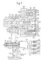
- Fig. 1 shows a variable valve timing mechanism (hereafter referred to as the "VVT mechanism") 11, an oil pump 15 for supplying oil through oil passages P1 and P2, an oil control valve (hereafter referred to as the "OCV”) 16 provided midway in each of the oil passages P1 and P2, and an electronic control unit (hereafter referred to as the "ECU”) 17 for controlling the OCV 16 in correspondence with the operating state of the engine, and so forth.
- VVT mechanism variable valve timing mechanism
- OCV oil control valve
- ECU electronice control unit
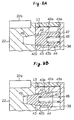
- a journal 12a of an intake-side cam shaft 12 is rotatably supported by an upper end face of a cylinder head 18 and a bearing cap 19.
- four pairs of cams 20 are provided on an outer peripheral portion of a proximal end side (right-hand side in Fig. 6) of the intake-side cam shaft 12. These cams 20 rotate together with the intake-side cam shaft 12 so as to open and close intake valves (not shown) respectively provided for the cylinders.
- an enlarged-diameter portion 21 is formed on a portion located more on the proximal end side than the journal 20a.
- a driven gear 22 is rotatably mounted on the outer periphery of the enlarged-diameter portion 21.
- a plurality of outer teeth 22a are formed on the outer peripheral portion of the driven gear 22.
- the outer teeth 22a mesh with outer teeth 24a of a drive gear 24 provided on an exhaust-side cam shaft 23.
- Four pairs of cams 25 are formed on the exhaust-side cam shaft 23 in the same way as the intake-side cam shaft 12. These cams 25 rotate together with the exhaust-side cam shaft 23 so as to open and close unillustrated exhaust valves respectively provided for the cylinders.
- the exhaust-side cam shaft 23 is rotatably supported by the cylinder head 18 and the bearing cap (not shown) in the same way as the intake-side cam shaft 12.
- a cam pulley 26 is fixed to one end portion of the exhaust-side cam shaft 23, and a timing belt 27 is wound around the pulley 26.
- the timing belt 27 is wound around a crank pulley (not shown) mounted on the crank shaft (not shown).
- the VVT mechanism 11 iprovided with a hollow cylindrical housing 28 and an internal rotor 29 disposed in the housing 28.
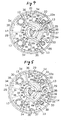
- the internal rotor 29 has a cylindrical portion 31 located in the center of the internal rotor 29 and four vanes 32 formed in such a manner as to project from the outer periphery of the cylindrical portion 31.
- the vanes 32 are arranged at equiangular intervals around the axis L of the intake-side cam shaft 12.
- projections 33 are formed at positions spaced apart predetermined intervals in the circumferential direction of the intake-side cam shaft 12 in such a manner as to project toward the axis of the intake-side cam shaft 12. Distal end faces of these projections 33 are in sliding contact with the outer peripheral surface of the cylindrical portion 31. Grooves 34 are formed between adjacent ones of the projections 33, and the vanes 32 are respectively located in the grooves 34.
- the distal end faces of the vanes 32 are in sliding contact with the inner peripheral wall of the housing 28.
- outer peripheral grooves 35 and 85 having rectangular cross sections are formed at distal end faces of the vanes 32 and at distal end faces of the projections 33.
- Seal members 36 and 86 are located in the outer peripheral grooves 35 and 85, and the seal members 36 and 86 are urged by leaf springs 37 and 87 in the direction of being disengaged from the grooves 35 and 85 in the radial direction of the intake-side cam shaft 12. Consequently, the distal end faces of the vanes 32 and the inner peripheral surface of the housing 28 are sealed by the seal members 36 and 86. Further, the movement of oil between an advanced-angle side hydraulic chamber 13 and a delayed-angle side hydraulic chamber 14 is restricted.
- the housing 28 has one end face abutting against one end face (the right-hand end face in Fig. 1) of the driven gear 22.
- a disk-shaped cover 38 is provided in such a manner as to cover the outer end faces of the housing 28 and the internal rotor 29.
- An insertion hole 39 is formed in a central portion of the cover 38.
- an insertion hole 40 is formed in a central portion of the cylindrical portion 31, and a mounting bolt 84 is inserted in the insertion holes 39 and 40.
- the mounting bolt 84 is threadedly engaged in a bolt hole 41 formed in a distal end portion of the intake-side cam shaft 12.
- the internal rotor 29 is fixed to the distal end portion of the intake-side cam shaft 12.
- a recess portion and a projecting portion which are not illustrated are respectively formed in the internal rotor 29 and the intake-side cam shaft 12. Through the relationship of the recess and the projection, the two members 29 and 12 rotate as a unit.
- the driven gear 22, the housing 28, and the cover 38 are integrally fixed by a plurality of bolts 30. Accordingly, the housing 28, the driven gear 22, and the cover 38 are integrally rotatably about the axis of the intake-side cam shaft 12.
- the driven gear 22 and the housing 28 constitute a first rotating body, and the internal rotor 29 constitutes a second rotating body.
- the internal rotor 29 is rotatable in both directions about the axis of the intake-side cam shaft 12 in correspondence with the magnitude of the pressure of the oil supplied to the hydraulic chambers 13 and 14.
- a through hole 42 with a circular cross section extending in the axial direction of the intake-side cam shaft 12 is formed in one of the vanes 32, and a lock pin 43 is disposed in the through hole 42.
- the through hole 42 is formed by a large-diameter portion 42a and a small-diameter portion 42b.
- the lock pin 43 has a hollow cylindrical shape with a bottom and is formed by a large-diameter portion 42a and a small-diameter portion 42b.
- the large-diameter portion 43a of the lock pin 43 is slidably fitted in the large-diameter portion 42a of the through hole 42, and the small-diameter portion 43b is slidably fitted in the small-diameter portion 42b.
- the space between the large-diameter portion 42a thereof and the small-diameter portion 43b of the lock pin 43 is formed as a hydraulic chamber 44.
- the hydraulic chamber 44 communicates with one of the delayed-angle side hydraulic chambers 14 through a first pressure oil passage 45 formed in a side portion of the internal vane 32, so that part of the oil in the delayed-angle side hydraulic chamber 14 can be supplied into the hydraulic chamber 44.
- An accommodating space 47 extending in the axial direction is formed in the lock pin 43, and a spring 48 is disposed in the accommodating space 47.
- the lock pin 43 is urged toward the proximal end side of the intake-side cam shaft 12 by the spring 48.
- a retaining hole 49 is formed in an end face of the driven gear 22 opposing the internal rotor 29.
- a distal end portion of the lock pin 43 can be fitted into this retaining hole 49.
- the retaining hole 49 communicates with one of the advanced-angle side hydraulic chambers 13 through a second pressure oil passage 50 formed in the driven gear 22, so that part of the oil in the advanced-angle side hydraulic chamber 13 can be supplied into the retaining hole 49.
- both the internal rotor 29 and the housing 28 are held in the positional relationship shown in Fig. 4. That is, the internal rotor 29 is disposed inside the housing 28 at a position where the rotational phase of the intake-side cam shaft 12 assumes the most delayed state with respect to the housing 28 (hereafter this position of the internal rotor 29 will be referred to as the "position of the most delayed angle").
- an advanced-angle side head oil passage 53 and a delayed-angle side head oil passage 54 are formed inside the cylinder head 18.
- the advanced-angle side head oil passage 53 communicates with the oil passage P1
- the delayed-angle side head oil passage 54 communicates with the oil passage P2.
- the head oil passages 53 and 54 are connectable to an oil pan 57 by means of the OCV 16, an oil filter 55, an oil pump 15, an oil strainer 56.
- the oil pump 15 is driven in conjunction with the running of the engine, the oil stored in the oil pan 57 is sucked by the oil pump 15.
- the oil is led into the oil pump 15 through the oil strainer 56, and is pressurized and discharged from the oil pump 15.
- the pressurized and discharged oil is sent to the OCV 16 through the oil filter 55, and the oil thus sent is selectively supplied to the head oil passages 53 and 54 by the OCV 16.
- Annular oil grooves 58 and 59 corresponding to the positions of the openings of the head oil passages 53 and 54 are respectively formed in an upper end portion of the cylinder head 18 and the bearing cap 19.
- a delayed-angle side shaft oil passage 60 extending in its axial direction is formed inside the intake-side cam shaft 12.
- the delayed-angle side shaft oil passage 60 communicates with the bolt hole 41.
- an annular circumferential groove 61 is formed along the outer periphery of the enlarged-diameter portion 12a of the intake-side cam shaft 12, and the circumferential groove 61 and the delayed-angle side shaft oil passage 60 communicate with each other through a communicating oil passage 62.
- a delayed-angle side oil hole 63 extending in the radial direction of the intake-side cam shaft 12 is formed inside the journal 12a.
- the delayed-angle side shaft oil passage 60 communicates with the oil groove 59 through this delayed-angle side oil hole 63. Accordingly, the oil in the delayed-angle side head oil passage 54 is supplied into the delayed-angle side shaft oil passage 60 through the oil groove 59 and the delayed-angle side oil hole 63.
- An advanced-angle side shaft oil passage 64 extending in parallel with the axial direction is formed inside the intake-side cam shaft 12.
- An advanced-angle side oil hole 65 extending in the radial direction of the intake-side cam shaft 12 is formed inside the journal 12a.
- the advanced-angle side shaft oil passage 64 communicates with the oil groove 58 through the advanced-angle side oil hole 65. Accordingly, the oil in the advanced-angle side head oil passage 53 is supplied into the advanced-angle side shaft oil passage 64 through the oil groove 58 and the advanced-angle side oil hole 65.
- each delayed-angle side supply passages 66 extending in the radial direction are formed inside the driven gear 22.
- the delayed-angle side supply passages 66 communicate with the circumferential groove 61 and the delayed-angle side hydraulic chambers 14.
- the oil supplied into the circumferential groove 61 from the delayed-angle side shaft oil passage 60 through the communicating oil passage 62 is supplied into the delayed-angle side hydraulic chambers 14 through the delayed-angle side supply passages 66.
- a projecting portion 67 is formed on the distal end face of the enlarged-diameter portion 21 of the intake-side cam shaft 12.
- a hole 68 for fitting with the projecting portion 67 is formed in the end face of the internal rotor 29 opposing the end face of the enlarged-diameter portion 21.
- the hole 68 surrounds the mounting bolt 84, and the interior of the hole 68 forms an annular advanced-angle side annular passage 46.
- the advanced-angle side shaft oil passage 64 is open in the advanced-angle side annular passage 46.
- FIG. 4 and 5 four advanced-angle side oil supply holes 69 extending in the radial direction are formed inside the internal rotor 29.
- the inner peripheral sides of the advanced-angle side oil supply holes 69 communicate with the advanced-angle side annular passage 46 and the advanced-angle side hydraulic chambers 13. Accordingly, the oil supplied into the advanced-angle side shaft oil passage 64 is supplied into the advanced-angle side hydraulic chambers 13 through the advanced-angle side oil supply holes 69.
- the OCV 16 controls the oil pressure supplied to the advanced-angle side hydraulic chambers 13 and the delayed-angle side hydraulic chambers 14.
- the OCV 16 controls the oil pressure supplied to the advanced-angle side hydraulic chambers 13 and the delayed-angle side hydraulic chambers 14.
- a casing 70 forming the OCV 16 has first to fifth ports 71 to 75.
- the first port 71 communicates with the delayed-angle side head oil passage 54
- the second port 72 communicates with the advanced-angle side head oil passage 53.
- the third and fourth ports 73 and 74 communicate with the oil pan 57
- the fifth port 75 communicates with the discharge side of the oil pump 15 through the oil filter 55.
- a spool 76 is provided inside the casing 70 in such a manner as to be capable of reciprocating in its axial direction.
- the spool 76 has four cylindrical valve elements 77.
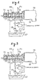
- the casing 70 is provided with an electromagnetic solenoid 78 for moving the spool from a first operating position shown in Fig. 2 to a second operating position shown in Fig. 1.
- a spring 79 is provided in the casing 70, and the spool 76 is urged toward the first operating position by this spring 79.
- the OCV 16 is controlled by the ECU 17 shown in Fig. 1.
- a revolution number sensor 80 for detecting the operating state of the engine
- an intake pressure sensor 81 for detecting the operating state of the engine
- a crank angle sensor 82 for detecting the rotational phase angle of the intake-side cam shaft 12.
- the ECU 17 detects the operating state of the engine and the rotational phase of the intake-side cam shaft 12 on the basis of detection signals of the sensors 80 to 83. Further, the ECU 17 determines the deviation between the actual rotational phase angle in the intake-side cam shaft 12 and a targeted rotational phase angle suitable for the operating state of the engine, and controls the OCV 16 and the VVT mechanism 11 so that the deviation is set to a predetermined value or less.
- the ECU 17 issues a command signal so that a current value supplied to the electromagnetic solenoid 78 provided in the OCV 18 is set to a maximum value.
- this command signal will be referred to as the 100% duty signal. Since the current value supplied to the electromagnetic solenoid 78 becomes maximum, the spool 76 moves to the second operating position shown in Fig. 1 against the urging force of the spring 79. As a result, the first port 72 and the fifth port 75 communicate with each other, and the second port 72 and the fourth port 74 communicate with each other. Accordingly, oil pressure is supplied to the delayed-angle side hydraulic chambers 14, while the oil in the advanced-angle side hydraulic chambers 13 is recirculated to the oil pan 57.
- vanes 32 are urged by the oil pressure within the delayed-angle side hydraulic chambers 14 which increased relative to the oil pressure in the advanced-angle side hydraulic chambers 13, so that the internal rotor 29 is rotated in the rotating direction of the intake-side cam shaft 12.
- the above-described control will be hereafter referred to as the delayed-angle control as the first oil pressure control.
- the ECU 17 issues a command signal so that a current value supplied to the electromagnetic solenoid 78 provided in the OCV 18 is set to zero.
- this command signal will be referred to as the 0% duty signal. Since the current value supplied to the electromagnetic solenoid 78 becomes zero, the spool 76 moves to the first operating position shown in Fig. 2 by the urging force of the spring 79. As a result, the second port 72 and the fifth port 75 communicate with each other, and the first port 71 and the third port 73 communicate with each other. Accordingly, oil pressure is supplied to the advanced-angle side hydraulic chambers 13, while the oil in the delayed-angle side hydraulic chambers 14 is recirculated to the oil pan 57.
- vanes 32 are urged by the oil pressure within the advanced-angle side hydraulic chambers 13 which increased relative to the oil pressure in the delayed-angle side hydraulic chambers 14, so that the internal rotor 29 is rotated in the opposite direction to the rotating direction of the intake-side cam shaft 12.
- the above-described control will be hereafter referred to as the advanced-angle control as the second oil pressure control.
- the ECU 17 issues a command signal so that a current value supplied to the electromagnetic solenoid 78 provided in the OCV 18 is set to a predetermined current value.
- this command signal will be referred to as the holding duty signal. Since the current value supplied to the electromagnetic solenoid 78 becomes the predetermined current value, the spool 76 moves to the intermediate holding position shown in Fig. 3 through the balance of the urging force of the spring 79 and the urging force generated by the electromagnetic solenoid 78. At this time, the first port 71 and the second port 72 communicate with each other. Accordingly, predetermined amounts of oil are supplied to the advanced-angle side hydraulic chambers 13 and the delayed-angle side hydraulic chambers 14.
- the above-described control will be hereafter referred to as the holding control as the third oil pressure control.
- Slight clearances are provided between movable members of the VVT mechanism 11 and the like so as to ensure their operation. Oil constantly leaks from these clearances. If the supply of oil pressure to the two hydraulic chambers 13 and 14 is stopped, the oil pressure within the hydraulic chambers 13 and 14 declines gradually due to the leakage of oil. If the state is left as it is, the oil pressure within the hydraulic chambers 13 and 14 ultimately becomes unable to hold the rotated position of the internal rotor 29. Therefore, to replenish the oil which leaked, it is necessary to supply the oil even during the aforementioned holding.
- the rotational phase angle is altered by appropriately effecting a changeover among the above-described three modes of operation control.
- auxiliary control is carried out for overcoming the trouble in which the cancellation of the aforementioned lock mechanism is temporarily stopped.
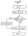
- a description will be given of this auxiliary control. It should be noted that this flowchart is based on the precondition that the ECU 17 is in a controlling state for effecting a changeover from delayed-angle control to advanced-angle control.
- the interior of the delayed-angle side hydraulic chambers 14 has been supplied with oil.
- the interior of the hydraulic chamber 44 has also been supplied with oil through the first pressure passage 45.
- the ECU 17 calculates the relative angle of rotation of the present internal rotor 29 and the driven gear 22. It should be noted that this relative angle of rotation uses as a reference the position of the most delayed angle, i.e., the position where the lock pin 43 and the retaining hole 49 are aligned with each other and the lock mechanism can be actuated, and this relative angle of rotation is quantized as the relative angle of rotation of the internal rotor 29 from that position.
- this value will be referred to as the VVT advanced-angle value, its unit is set as "°CA,” and the relative angle of rotation which is at a specific relative angle of rotation at the position of the most delayed angle is defined as "0°CA.”
- the ECU 17 determines whether the calculated VVT advanced-angle value is "0°CA" or a value other than the same. If the VVT advanced-angle value is a value other than "0°CA,” the ECU 17 outputs the 100% duty signal as it is, and the operation immediately shifts to the advanced-angle control.
- the ECU 17 outputs the holding duty signal for a fixed time duration.
- oil is supplied to the two oil passages P1 and P2 on the advanced-angle and delayed-angle sides. Accordingly, oil is supplied into the advanced-angle side hydraulic chambers 13 in addition to the delayed-angle side hydraulic chambers 14. Further, oil pressure is also supplied into the retaining hole 49 through the second pressure passage 50. Hence, by both the oil pressure within the hydraulic chamber 44 and the oil pressure within the retaining hole 49, the lock pin 43 is moved in the direction of being disengaged from the retaining hole 49 against the urging force of the spring 48.
- the time duration when the holding duty signal is being outputted is the time necessary for the oil pressure within the retaining hole 49 to increase to such an extent that it overcomes the urging force of the spring 48.
- the ECU After this holding duty signal is outputted for the predetermined time duration, the ECU outputs the 100% duty signal, and the operation shifts to the advanced-angle control. Although the oil pressure within the within the hydraulic chamber 44 declines due to this shift, since the oil pressure within the retaining hole 49 has already increased by this time, the lock pin 43 is able to maintain the present disengaged state against the urging force of the spring 48.
- the ECU 17 detects the operation stop of the engine on the basis of the fact that the unillustrated ignition switch is set to OFF, the ECU 17 outputs the 0% duty signal and effects the delayed-angle control.
- the VVT mechanism 11 is at the position of the most delayed angle and is in the state in which the rotational phase angle is fixed.
- the ECU 17 effects the delayed-angle control by outputting the 0% duty signal for the predetermined time duration, thereby holding the internal rotor 29 at the position of the most delayed angle.
- the operation is changed over to the advanced-angle control from the delayed-angle control at the aforementioned rotational phase angle at which the lock mechanism operates.
- the ECU 17 executes the auxiliary control mentioned earlier, i.e., the control for outputting the 100% duty signal after the holding duty signal is outputted for the predetermined time duration. Consequently, oil pressure which resists the urging force of the spring 48 constantly acts on the lock pin 43, thereby maintaining the state in which the lock pin 43 is disengaged from the retaining hole 49.
- valve timing controlling apparatus in accordance with the embodiment detailed above has the following characteristic features.
- this embodiment may be executed by being modified as follows.
- control similar to the auxiliary control described earlier may be executed also when a changeover is effected from the advanced-angle control to the delayed-angle control at the aforementioned specific relative angle of rotation. Namely, control is necessary in which a determination is made as to whether or not the present VVT advanced angle coincides with the aforementioned relative angle of rotation at the time of the changeover of control, and if they coincide, the 0% duty signal is outputted after the holding duty signal is outputted for a fixed time duration.
- An arrangement may be adopted in which the internal rotor 29 and the driven gear 22 rotate integrally, and the housing 28 and the cam shaft 12 rotate integrally.
- An arrangement may be provided such that the VVT mechanism 11 is provided with a cam pulley, and the pulley is rotated by the rotatively driving force of the crank shaft.
- An arrangement may be provided such that not more than three or not less than five vanes 32 are provided.
- the housing 28 and the driven gear 22 may be formed integrally.
- the cover 38 and the housing 28 may be formed integrally, and the intake-side cam shaft 12 and the internal rotor 29 may be formed integrally.
- the intake-side cam shaft 12 and the housing 28 may be formed integrally, or the driven gear 22 and the internal rotor 29 may be arranged to rotate integrally.
- An arrangement may be provided such that the cam pulley 26 is changed to a sprocket, and the timing melt 27 is changed to a timing chain.
- a structure may be provided such that the VVT mechanism is provided on the exhaust-side cam shaft so as to alter the opening/closing timing of the exhaust valve. Further, the VVT mechanisms may be provided on both the intake cam shaft 12 and the exhaust cam shaft 23 so as to alter the opening/closing timings of both the intake valve and the exhaust valve.
- an outstanding advantage can be exhibited in that, in the valve timing controlling apparatus, when the relative rotation of the second rotating body with respect to the first rotating body is effected, the trouble of the lock mechanism being unpreparedly set in a nonallowed state is favorably obviated, thereby further improving the reliability of the valve timing controlling apparatus.
- the lock mechanism is temporarily set in the nonallowed state, so that it is possible to prevent the necessary oil pressure from becoming insufficient.
- the invention is effective in the valve timing controlling apparatus in which the relative rotation of the second rotating body with respect to the first rotating body is not allowed in the state of a most delayed angle.
Claims (4)
- Dispositif de commande de calage de soupapes destiné à un moteur à combustion interne, comprenant :dans lequel l'angle de rotation relatif est commandé en effectuant l'une quelconque de la première commande de pression d'huile destinée à retarder l'angle de rotation relatif dudit second corps tournant, de la seconde commande de pression d'huile destinée à avancer l'angle de rotation relatif dudit second corps tournant, et de la troisième commande de pression d'huile destinée à fournir un fluide mis sous pression en vue d'équilibrer les pressions de fluide dans le moyen de changement d'angle de rotation relatif en vue de maintenir l'angle de rotation relatif dudit second corps tournant grâce auxdites pressions de fluide équilibrées,un premier corps tournant (22, 28) destiné à recevoir une force d'entraínement rotative depuis le moteur à combustion interne,un second corps tournant (29) dont l'angle de rotation relatif par rapport au premier corps tournant peut être déplacé,un moyen de changement d'angle de rotation relatif destiné à changer l'angle de rotation relatif dudit second corps tournant par rapport audit premier corps tournant par la pression d'huile,un mécanisme de blocage (43, 48, 49) qui est soumis à une commande de changement par la pression d'huile entre un état permis dans lequel la rotation relative dudit premier corps tournant et dudit second corps tournant est permise et un état non permis dans lequel elle n'est pas permise dans un état d'un angle de rotation relatif spécifique dudit second corps tournant par rapport audit premier corps tournant, etun moyen de commande de fourniture de pression d'huile (16, 17) destiné à commander la pression d'huile en vue de mettre en oeuvre ledit moyen de changement d'angle de rotation relatif et la pression d'huile destinée à mettre en oeuvre ledit mécanisme de blocage (43, 48, 49), de façon à transmettre la force d'entraínement rotative depuis le moteur à combustion interne vers un arbre à cames en vue d'entraíner la soupape d'admission et la soupape d'échappement au moyen dudit premier corps tournant et dudit second corps tournant,
ledit mécanisme de blocage (43, 48, 49) est limité à l'état permis par au moins la troisième commande de pression d'huile,
ledit mécanisme de blocage (43, 48, 49) est limité à l'état non permis lorsque aucune de la première commande de pression d'huile, de la seconde commande de pression d'huile et de la troisième commande de pression d'huile n'est effectuée, et
lorsque la première commande de pression d'huile ou la seconde commande de pression d'huile est lancée dans l'état de l'angle de rotation relatif spécifique, la troisième commande de pression d'huile est effectuée pour établir ledit mécanisme de blocage (43, 48, 49) dans l'état permis avant d'effectuer la première commande de pression d'huile ou bien la seconde commande de pression d'huile. - Dispositif de commande de calage de soupapes destiné à un moteur à combustion interne selon la revendication 1, dans lequel lorsqu'un changement est effectué depuis l'une de la première commande de pression d'huile et de la seconde commande de pression d'huile vers l'autre commande, la troisième commande de pression d'huile est effectuée afin d'établir ledit mécanisme de blocage (43, 48, 49) dans l'état permis afin d'effectuer l'autre commande de pression d'huile.
- Dispositif de commande de calage de soupapes destiné à un moteur à combustion interne selon la revendication 2, dans lequel l'angle de rotation relatif spécifique se trouve dans un état d'un angle le plus en retard, et lorsque ladite seconde commande de pression d'huile est lancée, la troisième commande de pression d'huile est effectuée pour établir ledit mécanisme de blocage (43, 48, 49) à l'état permis avant d'effectuer la seconde commande de pression d'huile.
- Dispositif de commande de calage de soupapes destiné à un moteur à combustion interne selon la revendication 1, dans lequel l'angle de rotation relatif spécifique se trouve dans un état d'un angle le plus en retard, et lorsque la seconde commande de pression d'huile est lancée, la troisième commande de pression d'huile est effectuée pour établir ledit mécanisme de blocage (43, 48, 49) à l'état permis afin d'effectuer la seconde commande de pression d'huile.
Applications Claiming Priority (3)
| Application Number | Priority Date | Filing Date | Title |
|---|---|---|---|
| JP9210859A JPH1150820A (ja) | 1997-08-05 | 1997-08-05 | 内燃機関のバルブタイミング制御装置 |
| JP210859/97 | 1997-08-05 | ||
| JP21085997 | 1997-08-05 |
Publications (2)
| Publication Number | Publication Date |
|---|---|
| EP0896129A1 EP0896129A1 (fr) | 1999-02-10 |
| EP0896129B1 true EP0896129B1 (fr) | 2002-12-11 |
Family
ID=16596290
Family Applications (1)
| Application Number | Title | Priority Date | Filing Date |
|---|---|---|---|
| EP98114708A Expired - Lifetime EP0896129B1 (fr) | 1997-08-05 | 1998-08-05 | Dispositif de commande de calage de soupape pour moteur à combustion interne |
Country Status (4)
| Country | Link |
|---|---|
| US (1) | US6006708A (fr) |
| EP (1) | EP0896129B1 (fr) |
| JP (1) | JPH1150820A (fr) |
| DE (1) | DE69810026T2 (fr) |
Cited By (4)
| Publication number | Priority date | Publication date | Assignee | Title |
|---|---|---|---|---|
| US8453616B2 (en) | 2009-10-27 | 2013-06-04 | Hilite Germany Gmbh | Vane-type motor cam phaser with a friction disc and mounting method |
| US8505582B2 (en) | 2010-05-03 | 2013-08-13 | Hilite Germany Gmbh | Hydraulic valve |
| US8662040B2 (en) | 2010-04-10 | 2014-03-04 | Hilite Germany Gmbh | Oscillating-motor camshaft adjuster having a hydraulic valve |
| US8752514B2 (en) | 2010-12-20 | 2014-06-17 | Hilite Germany Gmbh | Hydraulic valve for an oscillating motor adjuster |
Families Citing this family (37)
| Publication number | Priority date | Publication date | Assignee | Title |
|---|---|---|---|---|
| DE19823619A1 (de) * | 1998-05-27 | 1999-12-02 | Porsche Ag | Einrichtung zur relativen Drehlagenänderung einer Welle zum Antriebsrad |
| JP3719339B2 (ja) * | 1998-11-09 | 2005-11-24 | 日産自動車株式会社 | 内燃機関の可変動弁制御装置 |
| JP3730809B2 (ja) * | 1999-01-28 | 2006-01-05 | 三菱電機株式会社 | 内燃機関のバルブタイミング制御装置 |
| US6505585B1 (en) * | 1999-06-04 | 2003-01-14 | Unisia Jecs Corporation | Apparatus and method for controlling valve timing of an engine |
| DE19929394A1 (de) * | 1999-06-26 | 2000-12-28 | Schaeffler Waelzlager Ohg | Verfahren zur Ansteuerung einer Vorrichtung zum Variieren der Ventilsteuerzeiten einer Brennkraftmaschine, insbesondere einer Nockenwellen-Verstelleinrichtung mit hydraulisch entriegelbarer Startverriegelung |
| DE19929393A1 (de) | 1999-06-26 | 2000-12-28 | Schaeffler Waelzlager Ohg | Verfahren zur Ansteuerung einer Vorrichtung zum Variieren der Ventilsteuerzeiten einer Brennkraftmaschine, insbesondere einer Nockenwellen-Verstelleinrichtung mit hydraulisch entriegelbarer Startverriegelung |
| KR100406777B1 (ko) * | 1999-08-17 | 2003-11-21 | 가부시키가이샤 덴소 | 가변밸브 타이밍 제어장치 |
| JP2001102944A (ja) * | 1999-09-28 | 2001-04-13 | Sanyo Electric Co Ltd | ラジオ受信機におけるノイズ検出装置 |
| JP3850598B2 (ja) * | 1999-10-07 | 2006-11-29 | 株式会社日立製作所 | 内燃機関のベーン式バルブタイミング制御装置 |
| DE19951390A1 (de) | 1999-10-26 | 2001-05-03 | Schaeffler Waelzlager Ohg | Vorrichtung zur hydraulischen Drehwinkelverstellung einer Welle relativ zu einem Antriebsrad |
| EP1272741B1 (fr) * | 2000-04-14 | 2004-08-04 | Siemens Aktiengesellschaft | Procede pour reguler le fonctionnement d'un actionneur |
| JP4240756B2 (ja) * | 2000-05-10 | 2009-03-18 | アイシン精機株式会社 | 弁開閉時期制御装置 |
| JP4507151B2 (ja) * | 2000-10-06 | 2010-07-21 | 株式会社デンソー | バルブタイミング調整装置 |
| DE10050225A1 (de) * | 2000-10-11 | 2002-04-25 | Hydraulik Ring Gmbh | Betätigungseinrichtung zum Festlegen einer Nockenwelle eines Antriebsmotors eines Fahrzeuges, vorzugsweise eines Kraftfahrzeuges, in einer Startposition |
| DE10055334C2 (de) * | 2000-11-08 | 2003-10-30 | Porsche Ag | Vorrichtung zur relativen Drehwinkelverstellung einer Nockenwelle einer Brennkraftmaschine zu einem Antriebsrad |
| JP3605354B2 (ja) * | 2000-11-28 | 2004-12-22 | 三菱電機株式会社 | 内燃機関のバルブタイミング制御装置 |
| WO2002084081A1 (fr) * | 2001-04-12 | 2002-10-24 | Mitsubishi Denki Kabushiki Kaisha | Systeme de reglage de calage variable de soupapes |
| DE10150856B4 (de) * | 2001-10-15 | 2005-08-11 | Ina-Schaeffler Kg | Vorrichtung zum Verändern der Steuerzeiten von Gaswechselventilen einer Brennkraftmaschine, insbesondere Rotationskolben-Verstelleinrichtung zur Drehwinkelverstellung einer Nockenwelle gegenüber einer Kurbelwelle |
| DE10161698A1 (de) | 2001-12-15 | 2003-06-26 | Ina Schaeffler Kg | Vorrichtung zum Verändern der Steuerzeiten von Gaswechselventilen einer Brennkraftmaschine, insbesondere Einrichtung zur hydraulischen Drehwinkelverstellung einer Nockenwelle gegenüber einer Kurbelwelle |
| US6644258B1 (en) | 2002-04-22 | 2003-11-11 | Borgwarner Inc. | VCT mechanism having a lock pin adapted to release at a pressure higher than the pressure required to hold the lock pin in the released position |
| US6647936B2 (en) | 2002-04-22 | 2003-11-18 | Borgwarner Inc. | VCT lock pin having a tortuous path providing a hydraulic delay |
| JP3755655B2 (ja) * | 2002-04-23 | 2006-03-15 | 三菱電機株式会社 | 内燃機関のバルブタイミング制御装置 |
| JP3779234B2 (ja) * | 2002-04-24 | 2006-05-24 | 三菱電機株式会社 | 内燃機関のバルブタイミング制御装置 |
| JP4160408B2 (ja) * | 2003-01-17 | 2008-10-01 | 株式会社日立製作所 | 内燃機関のバルブタイミング制御装置 |
| DE10303991A1 (de) * | 2003-02-01 | 2004-08-05 | Hydraulik-Ring Gmbh | Einrichtung zur Verstellung einer Nockenwelle einer Brennkraftmaschine eines Kraftfahrzeuges |
| US20050045130A1 (en) * | 2003-08-27 | 2005-03-03 | Borgwarner Inc. | Camshaft incorporating variable camshaft timing phaser rotor |
| US20050045128A1 (en) * | 2003-08-27 | 2005-03-03 | Borgwarner Inc. | Camshaft incorporating variable camshaft timing phaser rotor |
| JP2005155373A (ja) * | 2003-11-21 | 2005-06-16 | Mitsubishi Electric Corp | バルブタイミング調整装置 |
| DE102005013402A1 (de) * | 2004-06-03 | 2005-12-22 | Ina-Schaeffler Kg | Vorrichtung zur Veränderung der Steuerzeiten einer Brennkraftmaschine |
| JP4016020B2 (ja) * | 2004-08-31 | 2007-12-05 | 株式会社日立製作所 | 内燃機関のバルブタイミング制御装置 |
| JP2006170026A (ja) * | 2004-12-14 | 2006-06-29 | Aisin Seiki Co Ltd | 内燃機関の弁開閉時期制御装置 |
| US7712441B2 (en) * | 2007-12-20 | 2010-05-11 | Gm Global Technology Operations, Inc. | Predicted engine oil pressure |
| DE102008021315A1 (de) * | 2008-04-29 | 2009-11-05 | Schaeffler Kg | Vorrichtung zur Verstellung der Drehlage einer Nockenwelle gegenüber einer Kurbelwelle eines Verbrennungsmotors |
| CN102066701B (zh) * | 2008-07-17 | 2013-06-12 | 三菱电机株式会社 | 可变阀定时调整装置用电磁阀及可变阀定时调整系统 |
| US8261708B2 (en) | 2010-04-07 | 2012-09-11 | Eaton Corporation | Control valve mounting system |
| CN103174488B (zh) * | 2013-03-18 | 2016-08-17 | 力帆实业(集团)股份有限公司 | 一种发动机总成 |
| DE102018126302A1 (de) * | 2018-01-30 | 2019-08-01 | ECO Holding 1 GmbH | Schwenkmotorversteller für eine Nockenwelle und Nockenwellenanordnung mit einer Nockenwelle und einem Schwenkmotorversteller |
Citations (1)
| Publication number | Priority date | Publication date | Assignee | Title |
|---|---|---|---|---|
| US4858572A (en) * | 1987-09-30 | 1989-08-22 | Aisin Seiki Kabushiki Kaisha | Device for adjusting an angular phase difference between two elements |
Family Cites Families (10)
| Publication number | Priority date | Publication date | Assignee | Title |
|---|---|---|---|---|
| JP3776463B2 (ja) * | 1992-11-30 | 2006-05-17 | 株式会社デンソー | 内燃機関における弁動作タイミング制御装置 |
| JP3374475B2 (ja) * | 1993-11-16 | 2003-02-04 | 株式会社デンソー | バルブタイミング調整装置 |
| US5823152A (en) * | 1995-06-14 | 1998-10-20 | Nippondenso Co., Ltd. | Control apparatus for varying a rotational or angular phase between two rotational shafts, preferably applicable to a valve timing control apparatus for an internal combustion engine |
| JP3146956B2 (ja) * | 1995-06-14 | 2001-03-19 | 株式会社デンソー | 内燃機関用バルブタイミング調整装置 |
| US5797361A (en) * | 1996-04-03 | 1998-08-25 | Toyota Jidosha Kabushiki Kaisha | Variable valve timing mechanism for internal combustion engine |
| DE69703670T2 (de) * | 1996-04-04 | 2001-05-10 | Toyota Motor Co Ltd | Variable Ventilzeitsteuervorrichtung für Brennkraftmaschine |
| JP3744594B2 (ja) * | 1996-05-15 | 2006-02-15 | アイシン精機株式会社 | 弁開閉時期制御装置 |
| JP3189679B2 (ja) * | 1996-05-24 | 2001-07-16 | トヨタ自動車株式会社 | 内燃機関のバルブ特性制御装置 |
| US5870983A (en) * | 1996-06-21 | 1999-02-16 | Denso Corporation | Valve timing regulation apparatus for engine |
| JP3787899B2 (ja) * | 1996-07-12 | 2006-06-21 | アイシン精機株式会社 | 弁開閉時期制御装置 |
-
1997
- 1997-08-05 JP JP9210859A patent/JPH1150820A/ja active Pending
-
1998
- 1998-08-05 US US09/129,610 patent/US6006708A/en not_active Expired - Lifetime
- 1998-08-05 DE DE69810026T patent/DE69810026T2/de not_active Expired - Lifetime
- 1998-08-05 EP EP98114708A patent/EP0896129B1/fr not_active Expired - Lifetime
Patent Citations (1)
| Publication number | Priority date | Publication date | Assignee | Title |
|---|---|---|---|---|
| US4858572A (en) * | 1987-09-30 | 1989-08-22 | Aisin Seiki Kabushiki Kaisha | Device for adjusting an angular phase difference between two elements |
Cited By (5)
| Publication number | Priority date | Publication date | Assignee | Title |
|---|---|---|---|---|
| US8453616B2 (en) | 2009-10-27 | 2013-06-04 | Hilite Germany Gmbh | Vane-type motor cam phaser with a friction disc and mounting method |
| US8794201B2 (en) | 2009-10-27 | 2014-08-05 | Hilite Germany Gmbh | Vane-type motor cam phaser with a friction disc and method for mounting a friction disc on a rotor |
| US8662040B2 (en) | 2010-04-10 | 2014-03-04 | Hilite Germany Gmbh | Oscillating-motor camshaft adjuster having a hydraulic valve |
| US8505582B2 (en) | 2010-05-03 | 2013-08-13 | Hilite Germany Gmbh | Hydraulic valve |
| US8752514B2 (en) | 2010-12-20 | 2014-06-17 | Hilite Germany Gmbh | Hydraulic valve for an oscillating motor adjuster |
Also Published As
| Publication number | Publication date |
|---|---|
| DE69810026T2 (de) | 2003-07-17 |
| EP0896129A1 (fr) | 1999-02-10 |
| US6006708A (en) | 1999-12-28 |
| DE69810026D1 (de) | 2003-01-23 |
| JPH1150820A (ja) | 1999-02-23 |
Similar Documents
| Publication | Publication Date | Title |
|---|---|---|
| EP0896129B1 (fr) | Dispositif de commande de calage de soupape pour moteur à combustion interne | |
| KR100998160B1 (ko) | 스풀 밸브 제어식 vct 로킹 핀 해제 메카니즘 | |
| US6386164B1 (en) | Valve timing control apparatus for internal combustion engine | |
| US6666181B2 (en) | Hydraulic detent for a variable camshaft timing device | |
| US6374787B2 (en) | Multi-position variable camshaft timing system actuated by engine oil pressure | |
| EP0845584B1 (fr) | Dispositif de variation de calage de distribution pour moteur à combustion interne | |
| EP2006500B1 (fr) | Déphaseur avec rotor à aubes et un pion de blocage | |
| US20020017255A1 (en) | Variable valve timing system | |
| JP2947165B2 (ja) | 内燃機関のバルブタイミング変更装置 | |
| KR20040020849A (ko) | 중앙 장착된 스풀 밸브의 위치를 제어하여 캠 페이서의노이즈를 감소시키는 방법 | |
| WO2020056256A1 (fr) | Déphaseur hybride avec verrouillage hydraulique dans une position intermédiaire | |
| JPH09250310A (ja) | 内燃機関のバルブタイミング変更装置 | |
| JPH10159519A (ja) | 内燃機関のバルブタイミング制御装置 | |
| JP3058080B2 (ja) | 内燃機関のバルブタイミング変更装置 | |
| JPH09250311A (ja) | 内燃機関のバルブタイミング変更装置 | |
| JPH10159520A (ja) | 内燃機関のバルブタイミング制御装置 | |
| JP2950263B2 (ja) | 内燃機関のバルブタイミング制御装置 | |
| JP3780594B2 (ja) | 内燃機関のバルブタイミング制御装置 | |
| JPH10159515A (ja) | 内燃機関のバルブタイミング制御装置 | |
| JP3221336B2 (ja) | 内燃機関のバルブタイミング制御装置 | |
| JPH09250312A (ja) | 内燃機関のバルブタイミング変更装置 | |
| JP4470339B2 (ja) | エンジンのバルブタイミング制御装置 | |
| JP4026461B2 (ja) | 弁開閉時期制御装置 | |
| JPH1089021A (ja) | 内燃機関のバルブタイミング可変装置 | |
| JPH09236003A (ja) | 内燃機関のバルブタイミング変更装置 |
Legal Events
| Date | Code | Title | Description |
|---|---|---|---|
| PUAI | Public reference made under article 153(3) epc to a published international application that has entered the european phase |
Free format text: ORIGINAL CODE: 0009012 |
|
| 17P | Request for examination filed |
Effective date: 19980824 |
|
| AK | Designated contracting states |
Kind code of ref document: A1 Designated state(s): DE FR GB |
|
| AX | Request for extension of the european patent |
Free format text: AL;LT;LV;MK;RO;SI |
|
| AKX | Designation fees paid |
Free format text: DE FR GB |
|
| 17Q | First examination report despatched |
Effective date: 20010918 |
|
| GRAG | Despatch of communication of intention to grant |
Free format text: ORIGINAL CODE: EPIDOS AGRA |
|
| GRAG | Despatch of communication of intention to grant |
Free format text: ORIGINAL CODE: EPIDOS AGRA |
|
| GRAH | Despatch of communication of intention to grant a patent |
Free format text: ORIGINAL CODE: EPIDOS IGRA |
|
| GRAH | Despatch of communication of intention to grant a patent |
Free format text: ORIGINAL CODE: EPIDOS IGRA |
|
| GRAA | (expected) grant |
Free format text: ORIGINAL CODE: 0009210 |
|
| AK | Designated contracting states |
Kind code of ref document: B1 Designated state(s): DE FR GB |
|
| REG | Reference to a national code |
Ref country code: GB Ref legal event code: FG4D |
|
| REF | Corresponds to: |
Ref document number: 69810026 Country of ref document: DE Date of ref document: 20030123 |
|
| ET | Fr: translation filed | ||
| PLBE | No opposition filed within time limit |
Free format text: ORIGINAL CODE: 0009261 |
|
| STAA | Information on the status of an ep patent application or granted ep patent |
Free format text: STATUS: NO OPPOSITION FILED WITHIN TIME LIMIT |
|
| 26N | No opposition filed |
Effective date: 20030912 |
|
| REG | Reference to a national code |
Ref country code: GB Ref legal event code: 746 Effective date: 20061025 |
|
| PGFP | Annual fee paid to national office [announced via postgrant information from national office to epo] |
Ref country code: DE Payment date: 20130731 Year of fee payment: 16 |
|
| PGFP | Annual fee paid to national office [announced via postgrant information from national office to epo] |
Ref country code: GB Payment date: 20130731 Year of fee payment: 16 Ref country code: FR Payment date: 20130808 Year of fee payment: 16 |
|
| REG | Reference to a national code |
Ref country code: DE Ref legal event code: R119 Ref document number: 69810026 Country of ref document: DE |
|
| GBPC | Gb: european patent ceased through non-payment of renewal fee |
Effective date: 20140805 |
|
| REG | Reference to a national code |
Ref country code: FR Ref legal event code: ST Effective date: 20150430 |
|
| REG | Reference to a national code |
Ref country code: DE Ref legal event code: R119 Ref document number: 69810026 Country of ref document: DE Effective date: 20150303 |
|
| PG25 | Lapsed in a contracting state [announced via postgrant information from national office to epo] |
Ref country code: GB Free format text: LAPSE BECAUSE OF NON-PAYMENT OF DUE FEES Effective date: 20140805 Ref country code: DE Free format text: LAPSE BECAUSE OF NON-PAYMENT OF DUE FEES Effective date: 20150303 |
|
| PG25 | Lapsed in a contracting state [announced via postgrant information from national office to epo] |
Ref country code: FR Free format text: LAPSE BECAUSE OF NON-PAYMENT OF DUE FEES Effective date: 20140901 |