EP0895023A2 - Einrichtung zur Montage einer Leuchte an einer Decke oder Gebäudewand - Google Patents
Einrichtung zur Montage einer Leuchte an einer Decke oder Gebäudewand Download PDFInfo
- Publication number
- EP0895023A2 EP0895023A2 EP98810718A EP98810718A EP0895023A2 EP 0895023 A2 EP0895023 A2 EP 0895023A2 EP 98810718 A EP98810718 A EP 98810718A EP 98810718 A EP98810718 A EP 98810718A EP 0895023 A2 EP0895023 A2 EP 0895023A2
- Authority
- EP
- European Patent Office
- Prior art keywords
- socket
- fastening
- lamp
- fastening member
- ceiling
- Prior art date
- Legal status (The legal status is an assumption and is not a legal conclusion. Google has not performed a legal analysis and makes no representation as to the accuracy of the status listed.)
- Withdrawn
Links
- 210000002105 tongue Anatomy 0.000 claims description 15
- 230000006978 adaptation Effects 0.000 description 1
- 239000011521 glass Substances 0.000 description 1
- 238000009434 installation Methods 0.000 description 1
- 230000001681 protective effect Effects 0.000 description 1
Images


Classifications
-
- F—MECHANICAL ENGINEERING; LIGHTING; HEATING; WEAPONS; BLASTING
- F21—LIGHTING
- F21V—FUNCTIONAL FEATURES OR DETAILS OF LIGHTING DEVICES OR SYSTEMS THEREOF; STRUCTURAL COMBINATIONS OF LIGHTING DEVICES WITH OTHER ARTICLES, NOT OTHERWISE PROVIDED FOR
- F21V21/00—Supporting, suspending, or attaching arrangements for lighting devices; Hand grips
- F21V21/02—Wall, ceiling, or floor bases; Fixing pendants or arms to the bases
- F21V21/03—Ceiling bases, e.g. ceiling roses
-
- F—MECHANICAL ENGINEERING; LIGHTING; HEATING; WEAPONS; BLASTING
- F21—LIGHTING
- F21V—FUNCTIONAL FEATURES OR DETAILS OF LIGHTING DEVICES OR SYSTEMS THEREOF; STRUCTURAL COMBINATIONS OF LIGHTING DEVICES WITH OTHER ARTICLES, NOT OTHERWISE PROVIDED FOR
- F21V23/00—Arrangement of electric circuit elements in or on lighting devices
- F21V23/06—Arrangement of electric circuit elements in or on lighting devices the elements being coupling devices, e.g. connectors
-
- F—MECHANICAL ENGINEERING; LIGHTING; HEATING; WEAPONS; BLASTING
- F21—LIGHTING
- F21V—FUNCTIONAL FEATURES OR DETAILS OF LIGHTING DEVICES OR SYSTEMS THEREOF; STRUCTURAL COMBINATIONS OF LIGHTING DEVICES WITH OTHER ARTICLES, NOT OTHERWISE PROVIDED FOR
- F21V3/00—Globes; Bowls; Cover glasses
- F21V3/02—Globes; Bowls; Cover glasses characterised by the shape
Definitions
- the invention relates to a device for mounting a lamp on a ceiling or building wall, with means for electrical Connect the lamp to a supply line and to one Fastening element for fastening the lamp to the ceiling or Building wall.
- Devices for attaching lights to a The ceiling or wall of a building is generally known.
- everyone is also known that the mounting of lights in particular Blankets are difficult and expensive.
- Usually only one Expert carry out this assembly correctly.
- So-called are also known Spots that are inserted into a track. The Assembling and disassembling such spots is relatively easy and usually possible without tools. Such tracks are not always desired, however, and mostly not easy to assemble. These spots are also not useful everywhere or desired.
- the invention has for its object a device to create the type mentioned, the assembly of lights of all Kind of a lot easier.
- the invention is measured in a generic device Claim 1 solved.
- the socket can not only be used to connect one Luminaire, but also for any electrical devices. It is also considered advantageous that, for example for collections any number of times and also simple Replacement of the lights is possible.
- the lights of a collection can also be used by a layperson, for example on the ceiling be assembled and replaced.
- the socket can both flush as well as surface-mounted. It can thus be Mount it very inconspicuously on a ceiling or building wall. Finally, with the device according to the invention Free movement of the socket is guaranteed in the respective country. Safety also takes into account the fact that the illuminant in a simple manner with the lamp removed in the de-energized state Condition is replaceable.
- the device according to the invention thus facilitates assembly and also ensures a much higher level of security. Finally, inexpensive production is also possible and guarantees free use in the respective country.
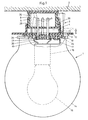
- FIG. 1 shows a device 3 according to the invention, with which a lamp 1 is mounted on a ceiling 2.
- the lamp 1 has a here schematically drawn protective glass 14, the one Surrounds illuminant 15.
- a version 16 is in the usual way attached with a bracket 17 to a lamp base 18.
- the Light 1 can also be any other light.
- Electrical wires 19 from are for the electrical connection the version 16 led to three connector pins 6.
- the connection takes place, for example, via conventional cable lugs 20
- the electrical connection passes through the lamp base 18 a central recess 21 is incorporated. If lamp 1 is a Low-voltage lighting, this indicates their free usability a conventional transformer, not shown here.
- the lamp 1 is attached to the device 3 on the ceiling 2 and electrically connected at the same time.
- This facility 3 consists of a socket 5, a fastener 4, a Unlocking part 11 and a plug part 22.
- the socket 5 has a cap-shaped housing 23 in which a conventional socket insert, not shown here, in one Recess 36 is housed and the corresponding socket holes 7 according to the usual standard type for households.
- the socket 5 is in a suitable manner, for example with the screw 24 shown in Figure 4, attached to the ceiling 2. Possible is also a flush mounting of the socket 5.
- the Socket 5 can be attached to any building wall, essential is only a sufficiently tensile anchorage of the Housing 23.
- the attachment of socket 5 on the ceiling 2 must have a tensile force that easily the weight of a Light 1 can accommodate.
- the traction should be at least 400 Newtons.
- the socket 5 and in particular the housing 23 is stable.
- the socket insert for mounting the socket 5 is the socket insert, not shown here, for the Switzerland usually uses T12, with screws on the ceiling 2 attached. With the screw 24 shown in Figure 4 the housing 23 screwed to the attached socket insert.
- the fastening screw 24 is designed so that the Light 1 can carry.
- the fastening member 4 is used for releasable attachment of the Light 1 on the socket 5.
- the fastening member 4 has a circular mounting base 25 on the edge and in an even arrangement three locking tongues 10 attached and in particular molded are. These locking tongues 10 form retaining clips and each have at a distance from the assembly floor 25 an inward Latch 26.
- In the mounting base 25 are three connector pins in the middle 6 attached, which form a plug part 22. This Connector pins 6 correspond to the three socket openings 7 arranged.
- the fastening member 4 is in accordance with Figure 1 Screws 34 or other suitable fasteners on Lamp base 18 attached. A version is also conceivable which the lamp base 18 and the fastening member 4 a unit form.
- the plate 13 is between the locking tongues 10 and has an upper edge 29 which when pushing upwards, the locking tongues 4 move elastically and radially moved outside.
- the upper edge 29 of the plate 13 slides at each locking tongue 10 on an inwardly inclined wedge surface 30 along.
- the locking tongues 10 are stretched and in a position in which the locking lugs 26 are outside the area of the shoulder 9.
- the Fastener 4 is thus unlocked and accordingly Light 1 detached from socket 5.
- the lamp 1 can thus be pulled away from socket 5 by hand.
- the Connector part 22 with the connector pins 6 also comes loose from the socket 5, so that the electrical Contact of lamp 1 to socket 5 is interrupted.
- the unlocking element 11 5 shows three holes 28.
- the unlocking element 11 To mount the lamp 1, the unlocking element 11 in brought the position shown in Figure 1 with solid lines. The lamp 1 is then in Figure 1 from above on the socket 5th postponed. Here, the connector pins 6 of the connector part 22 inserted into the socket openings 7. The lamp 1 must of course have a corresponding rotational position take in.
- the locking tabs 10 each with an inclined inner Surface 31 along an edge 32 (Fig. 2) of the housing 23 and then along a cylindrical lateral surface 33 up to the shoulder 9.
- the locking tongues 10 By engaging the edge 32 on the Surfaces 31 are the locking tongues 10 elastically radially outwards deflected. Have the locking tongues 26 reached the shoulder 29, so snap them onto shoulder 9.
- the locking tabs 10 are relaxed.
- This locking movement is preferably audible and / or noticeable.
- the person installing it can thus clearly recognize when the actuator 4 locks with the socket 5 and thus the lamp 1 is securely mounted and released can be.
- the unlocking element 11 pushed up and the Light 1 pulled down from socket 5.
- both assembling and disassembling the Luminaire 1 is possible with simple hand movements and without tools.
- FIGS 6 to 8 show a variant of the invention Device intended for flush mounting.
- This The device also has a socket 5 ', a fastening element 4 ', an unlocking part 11' and a plug part 22 '.
- a standard base plate 53 is provided here, which carries the socket 5 'and on a building wall 61st is assembled in a known manner.
- the socket 5 ' is mounted Condition with the outside of the wall with respect to a front Edge 44 essentially flush.
- the fastening member 4 ' has several, preferably at least three locking tabs 10 ', each at a front end Have latch 42. When locked, they grip Latches 42 according to Figure 8 each in an opening 40 of the cap 56 a. To release the locking tongues 10 ', the unlocking part 11 'in Figure 8 pushed up. A plate 13 'pushes here the locking lugs 42 radially inwards and thus lifts the Engagement of these locking lugs 42 on the cap of the socket 5 '. The plug part 22 'with the fastening member 4' can be thereupon can be removed with lamp 1.
- FIG. 6 shows, the socket 5 'is in an inlet box 60 housed in a building wall 61, in the Usually a blanket that is embedded.
- a base plate 53 On the inlet box 60 are a base plate 53 and a cover plate 54 are placed.
- the Base plate 53 is a standard plate and with brackets 52 on Socket insert 50 attached.
- the Cover plate 54 fastened to the building wall 61 with screws 55.
- FIG. 8 shows the two positions of an unlocking means 11 ', the position shown in dashed lines that Fastening member 4 'unlocked.
Landscapes
- Engineering & Computer Science (AREA)
- General Engineering & Computer Science (AREA)
- Connector Housings Or Holding Contact Members (AREA)
- Non-Portable Lighting Devices Or Systems Thereof (AREA)
- Arrangement Of Elements, Cooling, Sealing, Or The Like Of Lighting Devices (AREA)
- Building Environments (AREA)
Abstract
Description
Claims (18)
- Einrichtung zur Montage einer Leuchte an einer Decke oder Gebäudewand, mit Mitteln zum elektrischen Verbinden der Leuchte mit einer Versorgungsleitung und mit einem Befestigungsorgan zum Befestigen der Leuchte an der Decke oder Gebäudewand, gekennzeichnet durch:a) eine an der Decke oder Wand zu befestigende Steckdose,b) ein Befestigungsorgan, das an einer Leuchte anzubringen ist oder angebracht ist, und das Mittel zu seiner lösbaren Befestigung an der Steckdose aufweist,c) an der Steckdose angeordnete Mittel zur lösbaren Befestigung des Befestigungsorgans an der Steckdose, undd) ein im Befestigungsorgan integrierter Steckerteil zum elektrischen Verbinden der Leuchte mit der Steckdose.
- Einrichtung nach Anspruch 1, dadurch gekennzeichnet, dass der Steckerteil am Befestigungsorgan so angeordnet ist, dass bei einem Aufschieben des Befestigungsorgans auf die Steckdose gleichzeitig der Steckerteil mit der Steckdose verbunden wird.
- Einrichtung nach Anspruch 1 oder 2, dadurch gekennzeichnet, dass das Befestigungsorgan so ausgebildet ist, dass beim Einsetzen der Steckerstifte in Kontakthuchsen der Steckdose gleichzeitig das Befestigungsorgan selbsttätig an der Steckdose befestigt wird.
- Einrichtung nach einem der Ansprüche 1 bis 3, dadurch gekennzeichnet, dass die Steckdose am Aussenumfang ihres Gehäuses Mittel zur losbaren Befestigung des Befestigungsorgans an der Steckdose aufweist.
- Einrichtung nach Anspruch 4, dadurch gekennzeichnet, dass das Befestigungsorgan Rastmittel aufweist, die mit korrespondierenden Rastmitteln der Steckdose zusammenarbeiten.
- Einrichtung nach Anspruch 5, dadurch gekennzeichnet, dass als Rastmittel aussenseitig am Gehäuse eine oder mehrere Vertiefungen vorzugsweise eine umlaufende Rille oder Nut vorgesehen ist.
- Einrichtung nach einem der Ansprüche 1 bis 6, dadurch gekennzeichnet, dass das Befestigungsorgan mehrere Rastzungen aufweist, die am Gehäuse der Steckdose einrastbar sind.
- Einrichtung nach Anspruch 7, dadurch gekennzeichnet, dass das Befestigungsorgan Entriegelungsmittel aufweist.
- Einrichtung nach Anspruch 8, dadurch gekennzeichnet, dass das Entriegelungsmittel einen Ring oder einen Teller aufweist, der zum Spreizen der Verriegelungsmittel verschiebbar gelagert ist.
- Einrichtung nach einem der Ansprüche 1 bis 9, dadurch gekennzeichnet, dass das Befestigungsorgan mehrere radial elastisch auslenkbare Rastzungen aufweist und dass der Steckerteil etwa mittig zwischen diesen Rastzungen angeordnet ist.
- Einrichtung nach Anspruch 9 oder 10, dadurch gekennzeichnet, dass der Ring oder Teller seitlich vorstehend ist, derart, dass er bei befestigter Leuchte von Hand fassbar und verschiebbar ist.
- Einrichtung nach einem der Anspruche 4 bis 11, dadurch gekennzeichnet, dass das Befestigungsorgan zur Entriegelung ein mittelbar von Hand zu verschiebendes Spreizelement aufweist.
- Einrichtung nach einem der Ansprüche 1 bis 12, dadurch gekennzeichnet, dass sie einen Montageboden zur Befestigung des Steckerteils und des Befestigungsorgans an einer Leuchte aufweist.
- Steckdose für eine Einrichtung nach Anspruch 1, gekennzeichnet durch Mittel zur lösbaren Verriegelung einer Leuchte am Gehäuse der Steckdose.
- Steckdose nach Anspruch 14, dadurch gekennzeichnet, dass sie am Umfang ihres Gehäuses Befestigungsmittel, insbesondere eine Schulter aufweist.
- Steckdose nach Anspruch 15, dadurch gekennzeichnet, dass das Befestigungsmittel eine umlaufende Schulter ist.
- Befestigungsorgan für eine Einrichtung nach Anspruch 1, dadurch gekennzeichnet, dass es mit dem Steckerteil eine Einheit bildet.
- Befestigungsorgan nach Anspruch 17, dadurch gekennzeichnet, dass es Mittel zu seiner lösbaren Befestigung an einer Leuchte aufweist.
Applications Claiming Priority (3)
| Application Number | Priority Date | Filing Date | Title |
|---|---|---|---|
| CH184397 | 1997-07-31 | ||
| CH184397 | 1997-07-31 | ||
| CH1843/97 | 1997-07-31 |
Publications (2)
| Publication Number | Publication Date |
|---|---|
| EP0895023A2 true EP0895023A2 (de) | 1999-02-03 |
| EP0895023A3 EP0895023A3 (de) | 2000-12-27 |
Family
ID=4219914
Family Applications (1)
| Application Number | Title | Priority Date | Filing Date |
|---|---|---|---|
| EP98810718A Withdrawn EP0895023A3 (de) | 1997-07-31 | 1998-07-27 | Einrichtung zur Montage einer Leuchte an einer Decke oder Gebäudewand |
Country Status (1)
| Country | Link |
|---|---|
| EP (1) | EP0895023A3 (de) |
Cited By (7)
| Publication number | Priority date | Publication date | Assignee | Title |
|---|---|---|---|---|
| ES2182675A1 (es) * | 2000-02-04 | 2003-03-01 | Gabriel Scavella | Un portalampara. |
| WO2003058118A1 (en) * | 2002-01-14 | 2003-07-17 | Kjell Pettersen | Lamp holder for outdoor use |
| EP1180830A3 (de) * | 2000-08-17 | 2003-10-22 | Leo Bühler | Wand- und Deckenanschluss für elektrische Verbraucher |
| WO2008025752A1 (de) * | 2006-08-31 | 2008-03-06 | Michael Wahler | Anschlussvorrichtung für leuchten |
| DE102012006164A1 (de) * | 2012-03-28 | 2013-10-02 | Thomas Schulte | Vorrichtung zur Deckenmotage eines Elektrogeräts |
| RU2496052C2 (ru) * | 2008-10-27 | 2013-10-20 | ТЕКНА, Беслотен венотсап мет беперкте анспракелейкейд | Средства крепления встраиваемого точечного светильника в отверстии, выполненном в стенке, и встраиваемый светильник с такими средствами |
| RU2508500C2 (ru) * | 2010-02-15 | 2014-02-27 | Абб Аг | Светильник, в частности настенный светильник |
Family Cites Families (3)
| Publication number | Priority date | Publication date | Assignee | Title |
|---|---|---|---|---|
| US4300188A (en) * | 1979-10-01 | 1981-11-10 | Aldo Addario | Detachable lamp assembly |
| EP0252013A3 (de) * | 1986-07-04 | 1988-12-28 | Anton Bucher | Montagegarnitur für hängende Beleuchtungskörper |
| DE9214183U1 (de) * | 1992-10-21 | 1992-12-10 | Aliseo Lichttechnik GmbH, 5760 Arnsberg | Außenleuchte für Wandanschluß |
-
1998
- 1998-07-27 EP EP98810718A patent/EP0895023A3/de not_active Withdrawn
Non-Patent Citations (1)
| Title |
|---|
| None |
Cited By (10)
| Publication number | Priority date | Publication date | Assignee | Title |
|---|---|---|---|---|
| ES2182675A1 (es) * | 2000-02-04 | 2003-03-01 | Gabriel Scavella | Un portalampara. |
| ES2182675B1 (es) * | 2000-02-04 | 2004-06-01 | Gabriel Scavella | Un portalampara. |
| EP1180830A3 (de) * | 2000-08-17 | 2003-10-22 | Leo Bühler | Wand- und Deckenanschluss für elektrische Verbraucher |
| WO2003058118A1 (en) * | 2002-01-14 | 2003-07-17 | Kjell Pettersen | Lamp holder for outdoor use |
| WO2008025752A1 (de) * | 2006-08-31 | 2008-03-06 | Michael Wahler | Anschlussvorrichtung für leuchten |
| RU2466330C2 (ru) * | 2006-08-31 | 2012-11-10 | Михель ВАЛЕР | Соединительное устройство для светильников |
| RU2496052C2 (ru) * | 2008-10-27 | 2013-10-20 | ТЕКНА, Беслотен венотсап мет беперкте анспракелейкейд | Средства крепления встраиваемого точечного светильника в отверстии, выполненном в стенке, и встраиваемый светильник с такими средствами |
| RU2508500C2 (ru) * | 2010-02-15 | 2014-02-27 | Абб Аг | Светильник, в частности настенный светильник |
| DE102012006164A1 (de) * | 2012-03-28 | 2013-10-02 | Thomas Schulte | Vorrichtung zur Deckenmotage eines Elektrogeräts |
| DE102012006164B4 (de) * | 2012-03-28 | 2015-11-26 | Thomas Schulte | Vorrichtung zur Deckenmontage eines Elektrogeräts |
Also Published As
| Publication number | Publication date |
|---|---|
| EP0895023A3 (de) | 2000-12-27 |
Similar Documents
| Publication | Publication Date | Title |
|---|---|---|
| EP2169123B1 (de) | Berührungslos gesteuerte Wasserarmatur | |
| DE60024534T2 (de) | Deckenlüfter | |
| EP0779397B1 (de) | Abdeckanordnung | |
| EP1431765A2 (de) | Vorrichtung zur Ankopplung eines Stromzählers an eine Trägerplattform | |
| DE68923849T2 (de) | Elektrische Kontakteinheit für Leuchten. | |
| EP2059718B1 (de) | Anschlussvorrichtung für leuchten | |
| EP3000952A1 (de) | Baueinheit zur befestigung an einem schliessmechanismus einer tür oder eines fensters | |
| EP3428523B1 (de) | Befestigungsvorrichtung für leuchten und verwendung einer solchen befestigungsvorrichtung | |
| DE4314101A1 (de) | Armatur mit Bajonettverschluß | |
| DE2730859A1 (de) | Vorrichtung zum aufhaengen von wand- oder deckenleuchten | |
| DE102005022441B4 (de) | Kanal-Steckdose | |
| DE10011905C2 (de) | Hohlkörper für die Elektroinstallation | |
| DE102022108233A1 (de) | Badewannen-Einstiegshilfe | |
| DE3109894C2 (de) | ||
| DE4427769A1 (de) | Anschlußdose | |
| AT515550B1 (de) | Beleuchtungskörper | |
| DE10121231A1 (de) | Steckdose zur Steckdosenleiste erweiterbar | |
| DE4004648A1 (de) | Befestigungssystem fuer strahlerleuchten an decken- und wandflaechen | |
| EP0621443B1 (de) | Kopfstück für eine Langfeldleuchte | |
| DE102023110440B4 (de) | Befestigungsanordnung zum Befestigen einer Leuchtbaugruppe sowie Beleuchtungsvorrichtung mit mindestens einer derartigen Befestigungsanordnung | |
| DE29810467U1 (de) | System zum Befestigen einer Leuchte | |
| EP0676841B1 (de) | Einrichtung zur Versorgung eines elektrisch betätigten Gerätes im Sanitärbereich mit einer Niedervolt-Betriebsspannung | |
| EP1168556B1 (de) | Rahmen-Anordnung für Elektro-Installationsgeräte insbesondere in Unterputz-Ausführung | |
| DE10007370C1 (de) | Elektrische Steckvorrichtung | |
| DE19751112C2 (de) | Verbindungsvorrichtung |
Legal Events
| Date | Code | Title | Description |
|---|---|---|---|
| PUAI | Public reference made under article 153(3) epc to a published international application that has entered the european phase |
Free format text: ORIGINAL CODE: 0009012 |
|
| AK | Designated contracting states |
Kind code of ref document: A2 Designated state(s): AT BE CH CY DE DK ES FI FR GB GR IE IT LI LU MC NL PT SE |
|
| AX | Request for extension of the european patent |
Free format text: AL;LT;LV;MK;RO;SI |
|
| PUAL | Search report despatched |
Free format text: ORIGINAL CODE: 0009013 |
|
| AK | Designated contracting states |
Kind code of ref document: A3 Designated state(s): AT BE CH CY DE DK ES FI FR GB GR IE IT LI LU MC NL PT SE |
|
| AX | Request for extension of the european patent |
Free format text: AL;LT;LV;MK;RO;SI |
|
| AKX | Designation fees paid | ||
| REG | Reference to a national code |
Ref country code: DE Ref legal event code: 8566 |
|
| STAA | Information on the status of an ep patent application or granted ep patent |
Free format text: STATUS: THE APPLICATION IS DEEMED TO BE WITHDRAWN |
|
| 18D | Application deemed to be withdrawn |
Effective date: 20010628 |